EP2348617A2 - Coolant-cooled linear motor - Google Patents
Coolant-cooled linear motor Download PDFInfo
- Publication number
- EP2348617A2 EP2348617A2 EP11150481A EP11150481A EP2348617A2 EP 2348617 A2 EP2348617 A2 EP 2348617A2 EP 11150481 A EP11150481 A EP 11150481A EP 11150481 A EP11150481 A EP 11150481A EP 2348617 A2 EP2348617 A2 EP 2348617A2
- Authority
- EP
- European Patent Office
- Prior art keywords
- armature
- coolant
- reinforcing members
- motor
- cooling jackets
- Prior art date
- Legal status (The legal status is an assumption and is not a legal conclusion. Google has not performed a legal analysis and makes no representation as to the accuracy of the status listed.)
- Withdrawn
Links
Images





Classifications
-
- H—ELECTRICITY
- H02—GENERATION; CONVERSION OR DISTRIBUTION OF ELECTRIC POWER
- H02K—DYNAMO-ELECTRIC MACHINES
- H02K41/00—Propulsion systems in which a rigid body is moved along a path due to dynamo-electric interaction between the body and a magnetic field travelling along the path
- H02K41/02—Linear motors; Sectional motors
- H02K41/03—Synchronous motors; Motors moving step by step; Reluctance motors
- H02K41/031—Synchronous motors; Motors moving step by step; Reluctance motors of the permanent magnet type
-
- H—ELECTRICITY
- H02—GENERATION; CONVERSION OR DISTRIBUTION OF ELECTRIC POWER
- H02K—DYNAMO-ELECTRIC MACHINES
- H02K9/00—Arrangements for cooling or ventilating
- H02K9/19—Arrangements for cooling or ventilating for machines with closed casing and closed-circuit cooling using a liquid cooling medium, e.g. oil
-
- H—ELECTRICITY
- H02—GENERATION; CONVERSION OR DISTRIBUTION OF ELECTRIC POWER
- H02K—DYNAMO-ELECTRIC MACHINES
- H02K9/00—Arrangements for cooling or ventilating
- H02K9/22—Arrangements for cooling or ventilating by solid heat conducting material embedded in, or arranged in contact with, the stator or rotor, e.g. heat bridges
- H02K9/227—Heat sinks
-
- H—ELECTRICITY
- H02—GENERATION; CONVERSION OR DISTRIBUTION OF ELECTRIC POWER
- H02K—DYNAMO-ELECTRIC MACHINES
- H02K5/00—Casings; Enclosures; Supports
- H02K5/04—Casings or enclosures characterised by the shape, form or construction thereof
- H02K5/20—Casings or enclosures characterised by the shape, form or construction thereof with channels or ducts for flow of cooling medium
- H02K5/203—Casings or enclosures characterised by the shape, form or construction thereof with channels or ducts for flow of cooling medium specially adapted for liquids, e.g. cooling jackets
-
- H—ELECTRICITY
- H02—GENERATION; CONVERSION OR DISTRIBUTION OF ELECTRIC POWER
- H02K—DYNAMO-ELECTRIC MACHINES
- H02K9/00—Arrangements for cooling or ventilating
- H02K9/22—Arrangements for cooling or ventilating by solid heat conducting material embedded in, or arranged in contact with, the stator or rotor, e.g. heat bridges
- H02K9/223—Heat bridges
Definitions
- the present invention relates to a coolant-cooled linear motor.
- the linear motor used in factory automation equipments to drive a stage of a semiconductor exposure device or a liquid crystal exposure device or to feed a table of a machine tool.
- the linear motor includes permanent magnets making up a field magnet, and an armature having armature windings facing the magnetic pole surfaces of the permanent magnet in a magnetic space.
- the armature of the linear motor includes armature windings, a base plate for positioning and fixing the armature windings in place, a frame for fixing the base plate in place and a cover for sealing the frame.
- the frame includes a large coolant pool formed in the central area thereof. The armature windings are accommodated within the coolant pool. The side surfaces of the coolant pool are sealed by the cover.
- the frame is provided with a coolant inlet and a coolant outlet. Within the core of the frame, there are formed a coolant incoming path and a coolant outgoing path, which communicate with the coolant inlet and the coolant outlet, respectively (see, e.g., Japanese Patent Application Publication No. 2006-121813 ).
- the armature winding mounting space defined in the coolant pool of the frame is electromagnetically unnecessary. This results in an increase in the overall volume of the armature, including the frame, which contributes to generation of a thrust force in the armature. Therefore, it is difficult to increase the thrust force per unit volume (or the thrust force density). In order to increase the thrust force per unit volume of the armature, it is required to make the linear motor highly rigid and lightweight.
- the frame or cooling jackets serving as the coolant pool is made of a fiber resin material from the viewpoint of size reduction and strength enhancement.
- the fiber resin material shows high thermal conductivity in the plane direction.
- the thermal conductivity of the fiber resin material in the thickness direction depends on only the base resin and not the fibers.
- the fiber resin material shows reduced thermal conductivity in the thickness direction. This makes it difficult to transfer the heat generated in the armature windings to the coolant held in the coolant pool, resulting in an insufficient cooling performance.
- the linear motor can be made lightweight by changing the shape of the field magnet.
- the magnetic fields generated in the field magnet are.reduced.
- the electric current flowing through the armature is increased. This leads to an increase in the amount of heat generated in the armature.
- an object of the present invention to provide a coolant-cooled linear motor capable of enjoying an enhanced temperature performance, showing an increased cooling efficiency and achieving increased rigidity and reduced weight without reducing the thrust force density of an armature and the magnetic fields generated in a field magnet unit.
- a coolant-cooled linear motor including an armature including armature windings and a cooling jacket arranged to surround the armature windings, the cooling jacket unit including four cooling jackets defining four side faces parallel to the extension direction of the armature and two end blocks defining two opposite end faces in the extension direction of the armature, the cooling jackets and the end blocks being connected to one another in a box shape, each of the cooling jackets having an internal space to be supplied with a coolant; and a field magnet unit including a yoke made of a ferromagnetic material and permanent magnets arranged in the yoke, one of the armature and the field magnet unit making relative movement with respect to the other.
- Each of the cooling jackets may have a flat plate shape and includes a plurality of coolant flow paths defined therein.
- Each of the cooling jackets may be made of a fiber-reinforced plastic, ceramic or nonmagnetic stainless steel.
- the end blocks may respectively include a coolant inlet and a coolant outlet.
- Each of the cooling jackets may include an inner and an outer wall defining the internal space, first reinforcing members provided in the inner wall and second reinforcing members provided between the outer wall and the respective first reinforcing members, the first reinforcing members being higher in thermal conductivity than the inner wall, the second reinforcing members being lower in thermal conductivity than the first reinforcing member.
- the first reinforcing members and the corresponding second reinforcing members may be adhesively fixed to each other.
- Each of the first reinforcing members may include a flange portion formed at a peripheral portion thereof, insertion nuts fixed to the inner wall of each of the cooling jackets and bolts tightened to the corresponding insertion nuts through the flange portion to fix the first reinforcing member to the inner wall of each of the cooling jackets.
- Each of the first reinforcing members may include a flow path side surface and a recess portion formed on the flow path side surface
- each of the second reinforcing members includes a protrusion portion for engagement with the recess portion of the corresponding first reinforcing member
- an additional insertion nut is adhesively fixed to the protrusion portion
- a bolt is tightened to the additional insertion nut from the outer wall of the corresponding cooling jackets.
- the first reinforcing members and the second reinforcing members may be arranged in specified positions along the circumference of each of the armature windings.
- the first reinforcing members and the second reinforcing members may be arranged to be extended in the extension direction of the armature across the armature windings.
- Each of the first reinforcing members may be made of a fiber-reinforced plastic containing fibers oriented in the thickness direction, a resin material filled with filler of high thermal conductivity or a non-magnetic metal.
- the armature windings and the base may be preliminarily integrated by a resin molding and then covered by the cooling jackets with air gaps left between the base and the cooling jackets, the air gaps being filled with a sealant or an elastic resin having increased thermal conductivity.
- the armature further may include reinforcing members arranged between the armature windings and the base.
- Each of the first block and the second block has a labyrinth structure with a partition plate for baffling the flow of the coolant.
- the permanent magnets may include main pole magnets and auxiliary pole magnets alternately arranged on the yoke along the extension direction of the armature to have a Halbach array structure.
- the yoke may include air gaps formed in alignment with the auxiliary pole magnets, the air gaps having a width smaller than the width of the auxiliary pole magnets.
- the yoke includes non-magnetic members arranged in the air gaps and made of a material different from those of the permanent magnets and the yoke.
- a coolant-cooled linear motor including an armature including armature windings and a cooling jacket arranged to surround the armature windings, the cooling jacket unit including three cooling jackets defining three side faces parallel to the extension direction of the armature, a base of flat plate shape defining one side face parallel to the extension direction of the armature and two end blocks defining two opposite end faces in the extension direction of the armature, the cooling jackets and the end blocks being connected to one another in a box shape, each of the cooling jackets having an internal space to be supplied with a coolant; and a field magnet unit including a yoke made of a ferromagnetic material and permanent magnets arranged in the yoke, one of the armature and the field magnet unit making relative movement with respect to the other.
- the cooling jacket unit may further include flanges connecting the cooling jackets to the base.
- the cooling jackets and the flanges may be integrally made of carbon fibers.
- the cooling jacket is made of fiber-reinforced plastic containing glass fibers or carbon fibers, ceramics or stainless steel, one of non-magnetic metals. This contributes in making the cooling jacket highly rigid and lightweight.
- the field magnet unit lightweight and to increase the thrust force per mass of the field magnet unit. Since the thrust force required in driving the armature is decreased, it is possible to reduce the heat generation quantity of the armature.
- Fig. 1 is a perspective view showing a coolant-cooled linear motor in accordance with a first embodiment of the present invention.
- reference numeral “1" designates an armature
- reference numeral “2” designates a base plate
- reference numeral “3” designates armature windings
- reference numeral “8” designates a cooling jacket unit
- reference numeral "15” designates a field magnet unit
- reference numeral "16” designates a yoke
- reference numeral “16a” designates yoke fixing plates
- reference numeral “17” designates field-generating permanent magnets.
- the coolant-cooled linear motor includes an armature 1 (a so-called flat type linear motor armature) and a field magnet unit 15.
- the armature 1 includes a base plate 2, armature windings 3 fixed to the base plate 2 and a cooling jacket unit 8 arranged to surround the armature windings 3.
- the field magnet unit 15 is arranged to surround the cooling jacket unit 8 of the armature 1 with an air gap.
- the field magnet unit 15 includes a yoke 16 made of a ferromagnetic material and a plurality of field-generating permanent magnets 17 arranged along the moving direction of the linear motor and fixed to the yoke 16.
- the yoke 16 is supported by the yoke fixing plates 16a.
- the linear motor shown in Fig. 1 has a configuration in which the armature 1 serves as a fixed unit and the field magnet unit 15 serves as a movable unit capable of moving relative to the armature 1.
- the armature 1 may be used as a movable unit with respect to the field magnet unit 15 used as a fixed unit.
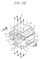
- Fig. 2A is an exploded perspective view showing the armature employed in the coolant-cooled linear motor of the first embodiment
- Fig. 2B is a partially enlarged perspective view of the area designated by "A" in Fig. 2A .
- the cooling jacket unit 8 includes first to fourth cooling jackets 8a, 8b, 8c and 8d arranged to surround the armature windings 3 and define four side faces of the armature 1 parallel to the extension direction of the armature 1 and first and second blocks 4 and 5 defining two opposite end faces of the armature 1 in the extension direction of the armature 1.
- Each of the cooling jackets 8a, 8b, 8c and 8d has an inner and an outer wall defining an internal space to which a coolant is supplied.
- the cooling jacket unit 8 is formed to have a box-like structure by arranging the first to fourth cooling jackets 8a, 8b, 8c and 8d and the first and second blocks 4 and 5 in a mutually opposing relationship.
- the cooling jacket unit 8 is formed into a flat shape and made of, e.g., fiber-reinforced plastic containing glass fibers or carbon fibers (i.e., carbon fiber reinforced plastic (CFRP) or glass fiber reinforced plastic (GFRP)), ceramics or a nonmagnetic metal such as a nonmagnetic stainless steel, thereby making the cooling jacket unit 8 highly rigid.
- CFRP carbon fiber reinforced plastic
- GFRP glass fiber reinforced plastic
- the first block 4 having a coolant inlet 6 and the second block 5 having a coolant outlet 7 are provided at the longitudinal opposite end portions of the first to fourth cooling jackets 8a, 8b, 8c and 8d so that a coolant can flow from one end portion of the cooling jacket unit 8 toward the other end thereof (in the extension direction of the armature 1).
- the entrances of the coolant flow paths of the first to fourth cooling jackets 8a, 8b, 8c and 8d communicate with the coolant inlet 6 of the first block 4, while the exits of the coolant flow paths of the first to fourth cooling jackets 8a, 8b, 8c and 8d communicate with the coolant outlet 7 of the second block 5.
- Through-holes h1 of the first to fourth cooling jackets 8a, 8b, 8c and 8d are aligned with threaded holes h2 formed on the upper, lower, left and right surfaces of the first block 4 and the second block 5. Screws M are inserted through the through-holes h1 and tightened into the threaded holes h2, thereby fixing the first to fourth cooling jackets 8a, 8b, 8c and 8d to the first block 4 and the second block 5.
- O-rings 9 are arranged between the first block 4 and the first to fourth cooling jackets 8a, 8b, 8c and 8d to secure fluid-tightness of the coolant flow paths around the coolant inlet 6.
- O-rings 9 are arranged between the second block 5 and the first to fourth cooling jackets 8a, 8b, 8c and 8d to secure fluid-tightness of the coolant flow paths around the coolant outlet 7 shown in Fig. 2A .
- Any seal members other than the O-rings may be used to increase the fluid-tightness of the coolant flow paths.
- the first block 4 with the coolant inlet 6 and/or the second block 5 with the coolant outlet 7 may be formed in a flat shape.
- the first block 4 and the second block 5 may not be provided with the coolant inlet and the coolant outlet but may merely serve as fixing members for keeping the cooling jacket unit 8 in a box-like shape.
- coolant inlets and coolant outlets are provided to each of the first to fourth cooling jackets 8a, 8b, 8c and 8d so that the coolant can flow through the first to fourth cooling jackets 8a, 8b, 8c and 8d independently.
- the coolant introduced from the coolant inlet 6 of the first block 4 flows through the coolant flow paths formed in the first block 4 and is distributed to the first to fourth cooling jackets 8a, 8b, 8c and 8d surrounding the armature windings 3 and defining four side faces parallel to the extension direction of the armature 1.
- the coolant flowing through the first to fourth cooling jackets 8a, 8b, 8c and 8d is collected in the second block 5 and is discharged through the coolant outlet 7.
- the heat generated in the armature windings 3 is dissipated by the coolant flowing through the first to fourth cooling jackets 8a, 8b, 8c and 8d.
- the conventional coolant-cooled linear motor is disadvantageous in that the insulation reliability of the linear motor is affected by the insulation performance of a coolant itself and further in that the winding space is sacrificed due to the use of a frame for holding the armature windings in place. In the present embodiment, however, there is no need to use a frame for holding the armature windings in the central area. This proportionately increases the space for accommodation of the armature windings.
- the cooling jackets of the cooling jacket unit for covering the armature windings are arranged on four side faces of the armature 1 so that all the four side faces parallel to the extension direction of the armature can be cooled with enhanced cooling efficiency. This makes it possible to increase the temperature reduction performance of the coolant-cooled linear motor. This also contributes in improving the linear motor performance and the thrust force density.
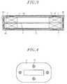
- Fig. 3 is a section view taken along line III - III in Fig. 1 , showing an armature of a coolant-cooled linear motor in accordance with a second embodiment of the present invention.
- each of the cooling jackets 8a, 8b, 8c and 8d has a coolant flow path 11 defined therein.
- each of the cooling jackets 8a, 8b, 8c and 8d includes first reinforcing members 12 arranged on the inner wall thereof and second reinforcing members 13 arranged on the outer wall thereof.
- the first reinforcing members 12 are greater in thermal conductivity than the walls of the cooling jackets 8a, 8b, 8c and 8d.
- the second reinforcing members 13 are lower in thermal conductivity than the first reinforcing members 12.
- the first reinforcing members 12 and the second reinforcing members 13 are fixed to the cooling jackets 8a, 8b, 8c and 8d by bonding or other fixing methods.
- the first reinforcing members 12 are made of a material having an enhanced high thermal conductivity in the thickness direction thereof, such as CFRP containing fibers oriented in the thickness direction, a resin material filled with filler of high thermal conductivity, a non-magnetic metal or the like.
- CFRP containing fibers oriented in the thickness direction such as CFRP containing fibers oriented in the thickness direction, a resin material filled with filler of high thermal conductivity, a non-magnetic metal or the like.
- the first reinforcing members 12 are capable of efficiently transferring the heat of the armature windings 3 to the coolant.
- the second reinforcing members 13 formed of a material having with a lower thermal conductivity than that of the first reinforcing members 12, such as resin or the like, between the first reinforcing members 12 and the outer wall of each of the cooling jackets 8a, 8b, 8c and 8d, it is possible to restrain the heat from being transferred to the outer wall, thereby suppressing temperature rise of the outer surfaces of the cooling jackets 8a, 8b, 8c and 8d.
- Fig. 4 is a top view illustrating the positional relationship between each of the armature windings of the coolant-cooled linear motor and the first reinforcing members 12 of the cooling jackets with the upper jacket 8a and the second reinforcing members 13 removed.
- the first reinforcing members 12 have a circular cross section and are arranged in specified positions along the circumference of each of the armature windings 3 (the second reinforcing members 13 are not shown in Fig. 4 ).
- This arrangement helps increase the heat transfer area, thereby making it possible to efficiently transfer the heat from the armature windings 3 to the coolant.
- such arrangement of the first reinforcing members 12 makes it possible to reliably reinforce the cooling jackets 8a, 8b, 8c and 8d of flat plate shape, each of which has the coolant flow path 11 with a narrow gap.
- the first reinforcing members 12 may have a rectangular cross section rather than the circular cross section. This also holds true in case of the second reinforcing members 13.
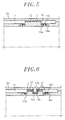
- Fig. 5 is an enlarged side section view showing a fixing structure of each of the first reinforcing members 12 to one of the first to fourth cooling jackets 8a, 8b, 8c and 8d in accordance with a third embodiment of the present invention, in which the cooling jacket 8a is representatively illustrated.
- the third embodiment differs from the second embodiment in that each of the first reinforcing members 12 is provided with a flange portion 12a at a peripheral portion thereof, insertion nuts 14a being fixed to the inner wall of the cooling jacket 8a on the opposite side to the coolant flow path 11 and bolts 14b being tightened to the respective nuts 14a through the flange portion 12a to fix each of the first reinforcing members 12 to the inner wall of the cooling jacket 8a.
- the first reinforcing members 12, the second reinforcing members 13 and the outer wall of the jacket 8a are adhesively bonded to one another.
- An O-ring 9' is arranged between the flange portion 12a of each of the first reinforcing members 12 and the inner wall of the cooling jacket 8a to secure fluid-tightness of the coolant flow path 11.
- the first reinforcing members 12 and the cooling jacket 8a are mechanically fixed to each other without resort to bonding. This makes it possible to assure increased fluid tightness of the coolant flow path 11. Any seal members other than the O-ring 9' may be used to secure the fluid-tightness of the coolant flow path 11.
- the nuts 14a are used to fix each of the first reinforcing members 12 to the inner wall of the cooling jacket 8a in the present embodiment, the first reinforcing members 12 may be fixed to the inner wall of the cooling jacket 8a by fixing the bolts 14b directly to the inner wall without using the nuts.
- Fig. 6 is an enlarged side section view showing the fixing structure of each of the second reinforcing members 13 to the first to fourth cooling jackets 8a, 8b, 8c and 8d in accordance with a fourth embodiment of the present invention, in which the cooling jacket 8a is representatively illustrated.
- each of the first reinforcing members 12 has a recess portion 12b formed in a surface thereof on the side of the coolant flow path 11, a protrusion portion 13a for engagement with the recess portion 12b being formed in each of the second reinforcing members 13, an insertion nut 14a' being preliminarily fixed in a depressed portion of the protrusion portion 13a by an adhesive agent and a bolt 14b' being tightened to the insertion nut 14a' from the outer wall of the cooling jacket 8a.
- Fig. 7 is a plan view showing a plurality of third reinforcing members in accordance with a fifth embodiment of the present invention, which is arranged inside each of the cooling jackets to rectilinearly extend along the extension direction of the armature.
- Fig. 8 is an enlarged view of the area designated by "B" in Fig. 7 , showing a positional relationship between the third reinforcing members and the armature windings.
- the fifth embodiment differs from the second to fourth embodiments in that, in place of the first reinforcing members 12 and the second reinforcing members 13 of the second to fourth embodiments, a plurality of third reinforcing members 22 rectilinearly extends along the extension direction of the armature 1 and a plurality of coolant flow paths 11 is defined between the third reinforcing portions 22 as shown in Fig. 7 . Therefore, the third reinforcing portions 22 are arranged to extend across the armature windings 3 as can be seen in Fig. 8 showing a positional relationship between the third reinforcing portions 22 and the armature windings 3.
- Each of the third reinforcing members 22 may be formed of two different members having different thermal conductivities such as the first and the second reinforcing members 12 and 13.
- the third reinforcing portions 22 provided inside of the cooling jacket 8a (or 8c) to rectilinearly extend along the extension direction of the armature 1 as shown in Figs. 7 and 8 , it is possible to provide a plurality of coolant flow paths 11 unlike the configuration in which the first reinforcing members 12 and the second reinforcing members 13 are arranged along each of the armature windings 3. This results in an increase in the flowing velocity of the coolant and the heat transfer area, consequently making it possible to efficiently transfer the heat from the armature windings 3 to the coolant and to greatly enhance the rigidity of the cooling jacket unit.
- Fig. 9 is a perspective view showing a coolant-cooled linear motor in accordance with a sixth embodiment of the present invention.
- reference numeral "100” designates an armature
- reference numeral "110” designates a base
- reference numeral "115” designates a field magnet unit
- reference numeral "116” designates a yoke
- reference numeral "117” designates field-generating permanent magnets.
- Fig. 10 is an exploded perspective view showing the armature employed in the linear motor of the sixth embodiment.
- the sixth embodiment differs from the first embodiment in that a base 110 of flat shape instead of one of the cooling jackets is arranged on one of the four side faces parallel to the extension direction of the armature. Further, although the armature employed in the linear motor of the first embodiment is a flat type, the armature of the sixth embodiment is a so-called T-type.
- the armature of the coolant-cooled linear motor includes armature windings 103, a cooling jacket unit of box-like shape for accommodating the armature windings 103 and the base 110 of flat plate shape or prismatic columnar shape attached to open end of the cooling jacket unit.
- the cooling jacket unit includes three cooling jackets 108a, 108b and 108c for defining three side faces of the cooling jacket unit parallel to the extension direction of the armature and two end jacket members 108e and 108f for defining two opposite end faces of the cooling jacket parallel to the extension direction of the armature. It is often the case that the armature windings 103 are bonded to and connected in a substrate 102.
- the armature windings 103 are fixed to the box-shape cooling jacket unit formed of the five jacket members 108a, 108b, 108c, 108e and 108f by bonding or resin-molding.
- the linear motor has a different fixing structure, it is possible to arrange the jacket members on plural faces and to enhance the temperature reduction performance.
- FIG. 10 shows an exploded perspective view of the armature of the linear motor, no detailed description will be made on the attachment structure of the respective jacket members since it is similar to that in the first embodiment.
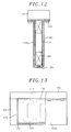
- Fig. 11 is a front section view showing the armature of the linear motor of the sixth embodiment, which is in an assembled state.
- Fig. 12 is a front section view showing another attachment example of a flange portion in the armature of the linear motor shown in Fig. 11 .
- the box-shaped cooling jacket unit is adhesively fixed to the base 110 through a flange 123 as a separate member.
- Fig. 12 shows an example in which the box-shaped cooling jacket unit and the flange 123 are integrally formed with each other using, e.g., CFRP.
- the configuration shown in Fig. 12 is capable of increasing the strength of the armature.
- carbon fibers are arranged in the direction perpendicular to the thrust force direction so that the mass of the armature can be sufficiently supported even if the armature is used in a horizontal posture.
- Fig. 13 is a side section view showing an armature of a coolant-cooled linear motor in accordance with a seventh embodiment of the present invention.
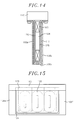
- Fig. 14 is a front section view of the armature shown in Fig. 13 .
- the seventh embodiment differs from the sixth embodiment in that, as shown in Figs. 13 and 14 , the armature windings 103 and the base 110 are preliminarily unified by a resin molding 124 and then covered with the box-shaped cooling jacket unit 108.
- air gaps 125 are provided between the resin molding 124 and the left, right and lower cooling jackets 108a, 108b and 108c as can be seen in Fig. 1 .
- An air gap 125 is also provided between the resin molding 124 and the end jacket member 108e as can be seen in Fig. 13 .
- a sealant or an elastic resin 125' having high thermal conductivity is filled in the air gaps 125.
- Provision of the air gaps 125 between the resin molding 124 and the cooling jacket unit 108 in the seventh embodiment as shown in Figs. 13 and 14 makes sure that, even if the resin molding 124 is expanded due to a sharp increase in the temperature of the armature windings 103, the expansion can be absorbed by the air gaps 125. This eliminates the possibility that stresses are applied to the cooling jacket unit 108. Moreover, the sealant or the elastic resin of high thermal conductivity filled in the air gaps 125 between the resin molding 124 and the cooling jacket unit 108 helps to increase the heat transfer from the armature windings 103 to the coolant, which makes it possible to avoid reduction in the cooling efficiency. This broadens the permissible range of temperature rise in the armature windings 103, consequently improving the thrust force performance of the linear motor.
- Fig. 15 is a side section view showing an armature of a coolant-cooled linear motor in accordance with an eighth embodiment of the present invention.
- the eighth embodiment differs from the sixth and seventh embodiments in that, in the coolant-cooled linear motor mounted with a cooling jacket unit having a plurality of coolant flow paths therein, fourth reinforcing members 126 are provided between the opposite side surfaces of the armature windings 103 and the base 110 and are fixed to the armature windings 103 by a resin molding 124.
- the fourth reinforcing members 126 are provided between the opposite side surfaces of the armature windings 103 and the base 110. This makes it possible to enhance the rigidity and vibration resistance of the armature. By arranging the fourth reinforcing members 126 between the armature windings 103 as well as at the longitudinal opposite ends of the armature, it is possible to expect a further enhanced reinforcing effect.
- Fig. 16 is a side section view showing an armature of a coolant-cooled linear motor in accordance with a ninth embodiment of the present invention.
- the ninth embodiment differs from the eighth embodiment in that, in the coolant-cooled linear motor mounted with a cooling jacket unit having a plurality of coolant flow paths therein, fifth reinforcing members 127 each having a substantially V-shaped tip end are arranged between upper spaces between the adjacent wirings and the base 110 and are fixed to the armature windings 103 by a resin molding 124.
- Provision of the fifth reinforcing members 127 between the upper inter-wiring spaces the base 110 in the ninth embodiment as shown in Fig. 16 makes sure that the rigidity and vibration resistance of the armature can be enhanced even when the reinforcing members cannot be provided between the armature windings 103 due to the narrow gap thereof.
- Fig. 17 is a perspective view showing a cooling jacket unit in accordance with a tenth embodiment of the present invention.
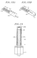
- Fig. 18A is an exploded perspective view showing a first block 204 with a coolant inlet 206
- Fig. 18B is an exploded perspective view showing a second block 205 with a coolant outlet 207, the first and the second bock 204 and 205 being constituent parts of the cooling jacket unit shown in Fig. 17
- Fig. 19 is a front section view showing an armature in accordance with the tenth embodiment of the present invention, in which the attachment direction of the armature is reversed to that in the sixth embodiment.
- the tenth embodiment is presented to more specifically describe the sixth embodiment shown in Fig. 10 .
- the cooling jacket unit 208 of the tenth embodiment includes the first block 204 with the coolant inlet 206 and the second block 205 with the coolant outlet 207, both of which are arranged at longitudinal opposite end portions of the cooling jacket unit 208.
- Each of the first block 204 and the second block 205 is provided with a partition plate 228 for temporarily baffling the flow of the coolant, a coolant pool portion 229 and a coolant communication groove 230.
- the tenth embodiment employs a labyrinth structure capable of assuring smooth inflow and outflow of the coolant.
- the coolant introduced from the coolant inlet 206 of the first block 204 is first accumulated in the coolant pool portion 229 of the first block 204. Then, as can be seen in Fig. 18A , the coolant flows over the partition plate 228 toward the coolant communication groove 230. The coolant is distributed to the first cooling jacket 208a, the second cooling jacket 208b and the third cooling jacket 208c through coolant communication holes 231. Thereafter, the coolant is gathered in the coolant communication groove 230 through the coolant communication holes 231 of the second block 205 shown in Fig. 18B . The coolant thus gathered flows over the partition plate 228 and is discharged from the coolant outlet 207 through the coolant pool portion 209. In other words, the coolant cannot be discharged toward the coolant outlet 207 unless it does not flow over the partition plate 228 provided in the second block 205.
- the partition plate 28 is extended to a height higher than the coolant communication holes 231.
- the coolant is filled in the entire flow paths.
- the second cooling jacket 208b can be filled with the coolant by adjusting the height of the partition plate 228.
- the labyrinth structure mentioned above is provided in the coolant outlet side as well as in the coolant inlet side. Therefore, the coolant is filled in the entire flow paths under the same principle even when the coolant inlet is interchanged with the coolant outlet. This can contribute in standardizing the components and improving the ease of work.
- the forgoing description is directed to a case where the armature is attached in the posture shown in Fig. 19 . If the attachment posture of the armature is turned over, the coolant inlet and the coolant outlet are positioned at positions higher than the entire flow paths. In this case, the coolant is filled in the entire flow paths regardless of the labyrinth structure. This makes it possible to arbitrarily set the attachment posture of the armature.
- Fig. 20 is a plan section view showing a field magnet unit of a linear motor in accordance with an eleventh embodiment of the present invention.
- reference numeral '16' designates a yoke
- reference numeral '17' designates field-generating permanent magnets
- reference numeral '17a' designates main pole magnets
- reference numeral '17b' designates auxiliary pole magnets
- reference numeral '18' designates air gaps. Allows '20' designate the directions of magnetic fields.
- the field-generating permanent magnets 17 have a Halbach array structure in which the main pole magnets 17a and the auxiliary pole magnets 17b are alternately arranged on the yoke 16 along the extension direction of the armature.
- the air gaps 18 having a width WB smaller than the width W of the auxiliary pole magnets 17b are formed in the areas of the yoke 16 corresponding to the auxiliary pole magnets 17b.
- Fig. 21 is a plan section view showing another example of the field magnet unit of the linear motor in accordance with the eleventh embodiment of the present invention.
- reference numeral '19' designates non-magnetic members.
- non-magnetic members 19 made of a material different from those of the permanent magnets 17 and the yoke 16 are used in place of the air gaps 18 of the yoke 16 shown in Fig. 20 .
- the eleventh embodiment configured as above, it is possible to make the field magnet unit lightweight without impairing the thrust force enhancing characteristics and the thrust force variation reducing characteristics of the linear motor having the field magnet unit of Halbach array structure. In addition, it is possible to provide a linear motor capable of reducing the heat generation quantity of the armature.
- the non-magnetic members 19 may be made of any material lighter than the yoke 16 and the permanent magnets 17, e.g., resins, ceramics or metals such as titanium and the like.
Landscapes
- Engineering & Computer Science (AREA)
- Power Engineering (AREA)
- Physics & Mathematics (AREA)
- Chemical & Material Sciences (AREA)
- Combustion & Propulsion (AREA)
- Electromagnetism (AREA)
- Linear Motors (AREA)
- Motor Or Generator Cooling System (AREA)
Abstract
In a coolant-cooled linear motor includes an armature (1) including armature windings (3) and a cooling jacket arranged to surround the armature windings (3), the cooling jacket unit (8) includes four cooling jackets defining four side faces parallel to the extension direction of the armature (1) and two end blocks defining two opposite end faces in the extension direction of the armature, the cooling jackets and the end blocks being connected to one another in a box shape. Each of the cooling jackets has an internal space to be supplied with a coolant; and a field magnet unit (15) includes a yoke (16) made of a ferromagnetic material and permanent magnets (17) arranged in the yoke, one of the armature and the field magnet unit making relative movement with respect to the other.
Description
- The present invention relates to a coolant-cooled linear motor.
- Conventionally, there has been proposed a linear motor used in factory automation equipments to drive a stage of a semiconductor exposure device or a liquid crystal exposure device or to feed a table of a machine tool. In order to achieve an increase in speed and accuracy of feeding or processing operations, the linear motor includes permanent magnets making up a field magnet, and an armature having armature windings facing the magnetic pole surfaces of the permanent magnet in a magnetic space.
- The armature of the linear motor includes armature windings, a base plate for positioning and fixing the armature windings in place, a frame for fixing the base plate in place and a cover for sealing the frame. The frame includes a large coolant pool formed in the central area thereof. The armature windings are accommodated within the coolant pool. The side surfaces of the coolant pool are sealed by the cover. The frame is provided with a coolant inlet and a coolant outlet. Within the core of the frame, there are formed a coolant incoming path and a coolant outgoing path, which communicate with the coolant inlet and the coolant outlet, respectively (see, e.g., Japanese Patent Application Publication No.
2006-121813 - In the armature of the conventional linear motor, however, the armature winding mounting space defined in the coolant pool of the frame is electromagnetically unnecessary. This results in an increase in the overall volume of the armature, including the frame, which contributes to generation of a thrust force in the armature. Therefore, it is difficult to increase the thrust force per unit volume (or the thrust force density). In order to increase the thrust force per unit volume of the armature, it is required to make the linear motor highly rigid and lightweight.
- It is known that the frame or cooling jackets serving as the coolant pool is made of a fiber resin material from the viewpoint of size reduction and strength enhancement. The fiber resin material shows high thermal conductivity in the plane direction. However, the thermal conductivity of the fiber resin material in the thickness direction depends on only the base resin and not the fibers. Thus, the fiber resin material shows reduced thermal conductivity in the thickness direction. This makes it difficult to transfer the heat generated in the armature windings to the coolant held in the coolant pool, resulting in an insufficient cooling performance.
- In case where the armature windings undergo sharp temperature rise, they are thermally expanded. In contrast, the cooling jacket is cooled by the coolant at all times, consequently undergoing limited temperature rise and showing little thermal expansion. Due to the difference in thermal expansion, internal stresses are generated between the armature windings and the cooling jacket.
- In the meantime, the linear motor can be made lightweight by changing the shape of the field magnet. In this case, however, the magnetic fields generated in the field magnet are.reduced. Moreover, if the field magnet is used as a movable body, the electric current flowing through the armature is increased. This leads to an increase in the amount of heat generated in the armature.
- It is, therefore, an object of the present invention to provide a coolant-cooled linear motor capable of enjoying an enhanced temperature performance, showing an increased cooling efficiency and achieving increased rigidity and reduced weight without reducing the thrust force density of an armature and the magnetic fields generated in a field magnet unit.
- In accordance with an aspect of the present invention, there is provided a coolant-cooled linear motor including an armature including armature windings and a cooling jacket arranged to surround the armature windings, the cooling jacket unit including four cooling jackets defining four side faces parallel to the extension direction of the armature and two end blocks defining two opposite end faces in the extension direction of the armature, the cooling jackets and the end blocks being connected to one another in a box shape, each of the cooling jackets having an internal space to be supplied with a coolant; and a field magnet unit including a yoke made of a ferromagnetic material and permanent magnets arranged in the yoke, one of the armature and the field magnet unit making relative movement with respect to the other.
- Each of the cooling jackets may have a flat plate shape and includes a plurality of coolant flow paths defined therein.
- Each of the cooling jackets may be made of a fiber-reinforced plastic, ceramic or nonmagnetic stainless steel.
- The end blocks may respectively include a coolant inlet and a coolant outlet.
- Each of the cooling jackets may include an inner and an outer wall defining the internal space, first reinforcing members provided in the inner wall and second reinforcing members provided between the outer wall and the respective first reinforcing members, the first reinforcing members being higher in thermal conductivity than the inner wall, the second reinforcing members being lower in thermal conductivity than the first reinforcing member.
- The first reinforcing members and the corresponding second reinforcing members may be adhesively fixed to each other.
- Each of the first reinforcing members may include a flange portion formed at a peripheral portion thereof, insertion nuts fixed to the inner wall of each of the cooling jackets and bolts tightened to the corresponding insertion nuts through the flange portion to fix the first reinforcing member to the inner wall of each of the cooling jackets.
- Each of the first reinforcing members may include a flow path side surface and a recess portion formed on the flow path side surface, each of the second reinforcing members includes a protrusion portion for engagement with the recess portion of the corresponding first reinforcing member, an additional insertion nut is adhesively fixed to the protrusion portion, and a bolt is tightened to the additional insertion nut from the outer wall of the corresponding cooling jackets.
- The first reinforcing members and the second reinforcing members may be arranged in specified positions along the circumference of each of the armature windings.
- The first reinforcing members and the second reinforcing members may be arranged to be extended in the extension direction of the armature across the armature windings.
- Each of the first reinforcing members may be made of a fiber-reinforced plastic containing fibers oriented in the thickness direction, a resin material filled with filler of high thermal conductivity or a non-magnetic metal.
- The armature windings and the base may be preliminarily integrated by a resin molding and then covered by the cooling jackets with air gaps left between the base and the cooling jackets, the air gaps being filled with a sealant or an elastic resin having increased thermal conductivity.
- The armature further may include reinforcing members arranged between the armature windings and the base.
- Each of the first block and the second block has a labyrinth structure with a partition plate for baffling the flow of the coolant.
- The permanent magnets may include main pole magnets and auxiliary pole magnets alternately arranged on the yoke along the extension direction of the armature to have a Halbach array structure.
- The yoke may include air gaps formed in alignment with the auxiliary pole magnets, the air gaps having a width smaller than the width of the auxiliary pole magnets.
- The yoke includes non-magnetic members arranged in the air gaps and made of a material different from those of the permanent magnets and the yoke.
- In accordance with another aspect of the present invention, there is provided a coolant-cooled linear motor including an armature including armature windings and a cooling jacket arranged to surround the armature windings, the cooling jacket unit including three cooling jackets defining three side faces parallel to the extension direction of the armature, a base of flat plate shape defining one side face parallel to the extension direction of the armature and two end blocks defining two opposite end faces in the extension direction of the armature, the cooling jackets and the end blocks being connected to one another in a box shape, each of the cooling jackets having an internal space to be supplied with a coolant; and a field magnet unit including a yoke made of a ferromagnetic material and permanent magnets arranged in the yoke, one of the armature and the field magnet unit making relative movement with respect to the other.
- The cooling jacket unit may further include flanges connecting the cooling jackets to the base.
- The cooling jackets and the flanges may be integrally made of carbon fibers.
- In accordance with the present invention, no frame is arranged in the armature. This makes it possible to broaden the winding wire accommodation space, greatly contributing to the improvement of the performance and thrust force density of the linear motor. The cooling jacket is made of fiber-reinforced plastic containing glass fibers or carbon fibers, ceramics or stainless steel, one of non-magnetic metals. This contributes in making the cooling jacket highly rigid and lightweight.
- Further, it is possible to efficiently transfer the heat from the armature windings to the coolant, thereby suppressing the temperature rise on the outer surface of the cooling jacket and enhancing the cooling efficiency.
- In addition, it is possible to absorb the internal stresses generated by a sharp increase in the temperature of the armature windings, thereby avoiding reduction in the cooling efficiency.
- Moreover, it is possible to enhance the rigidity and vibration resistance of the armature.
- Furthermore, it is possible to keep the cooling efficiency unchanged even when the attachment posture of the armature is set arbitrarily in the linear motor.
- In addition, it is possible to make the field magnet unit lightweight and to increase the thrust force per mass of the field magnet unit. Since the thrust force required in driving the armature is decreased, it is possible to reduce the heat generation quantity of the armature.
- The above and other objects and features of the present invention will become apparent from the following description of embodiments, given in conjunction with the accompanying drawings, in which:
-
Fig. 1 is a perspective view showing a coolant-cooled linear motor in accordance with a first embodiment of the present invention; -
Fig. 2A is an exploded perspective view showing an armature employed in the coolant-cooled linear motor of the first embodiment, andFig. 2B is a partially enlarged perspective view of the area designated by "A" inFig. 2A ; -
Fig. 3 is a section view showing an armature of a coolant-cooled linear motor in accordance with a second embodiment of the present invention; -
Fig. 4 is a top view showing a positional relationship between the armature windings of the linear motor and the reinforcing member of the cooling jacket unit; -
Fig. 5 is an enlarged side section view showing a fixing portion of a reinforcing member in accordance with a third embodiment of the present invention; -
Fig. 6 is an enlarged side section view showing a fixing portion of a reinforcing member in accordance with a fourth embodiment of the present invention; -
Fig. 7 is a plan view showing a plurality of reinforcing members in accordance with a fifth embodiment of the present invention, which is arranged inside the cooling jacket unit to be rectilinearly extended along the extension direction of the armature; -
Fig. 8 is an enlarged view of an area designated by "B" inFig. 7 , showing a positional relationship between the reinforcing members and the armature windings; -
Fig. 9 is a perspective view showing a coolant-cooled linear motor in accordance with a sixth embodiment of the present invention; -
Fig. 10 is an exploded perspective view showing an armature employed in the linear motor of the sixth embodiment; -
Fig. 11 is a front section view showing the armature of the linear motor of the sixth embodiment, which is in an assembled state; -
Fig. 12 is a front section view showing another attachment example of a flange portion in the armature of the linear motor; -
Fig. 13 is a side section view showing an armature of a coolant-cooled linear motor in accordance with a seventh embodiment of the present invention; -
Fig. 14 is a front section view of the armature shown inFig. 13 ; -
Fig. 15 is a side section view showing an armature of a coolant-cooled linear motor in accordance with an eighth embodiment of the present invention; -
Fig. 16 is a side section view showing an armature of a coolant-cooled linear motor in accordance with a ninth embodiment of the present invention; -
Fig. 17 is a perspective view showing a cooling jacket unit in accordance with a tenth embodiment of the present invention; -
Fig. 18A is an exploded perspective view showing a first block with a coolant inlet as one of constituent parts of the cooling jacket unit shown inFig. 17 , andFig. 18B is an exploded perspective view showing a second block with a coolant outlet as another of constituent parts of the cooling jacket unit shown inFig. 17 ; -
Fig. 19 is a front section view showing an armature in accordance with the tenth embodiment of the present invention, in which the attachment direction of the armature is restricted; -
Fig. 20 is a plan section view showing a field magnet unit of a linear motor in accordance with an eleventh embodiment of the present invention; and -
Fig. 21 is a plan section view showing another example of the field magnet unit of the linear motor in accordance with the eleventh embodiment of the present invention. - Embodiments of the present invention will now be described with reference to the accompanying drawings which form a part hereof.
-
Fig. 1 is a perspective view showing a coolant-cooled linear motor in accordance with a first embodiment of the present invention. InFig. 1 , reference numeral "1" designates an armature, reference numeral "2" designates a base plate, reference numeral "3" designates armature windings, reference numeral "8" designates a cooling jacket unit, reference numeral "15" designates a field magnet unit, reference numeral "16" designates a yoke, reference numeral "16a" designates yoke fixing plates, and reference numeral "17" designates field-generating permanent magnets. - Referring to
Fig. 1 , the coolant-cooled linear motor includes an armature 1 (a so-called flat type linear motor armature) and afield magnet unit 15. Thearmature 1 includes abase plate 2,armature windings 3 fixed to thebase plate 2 and acooling jacket unit 8 arranged to surround thearmature windings 3. Thefield magnet unit 15 is arranged to surround thecooling jacket unit 8 of thearmature 1 with an air gap. Thefield magnet unit 15 includes ayoke 16 made of a ferromagnetic material and a plurality of field-generatingpermanent magnets 17 arranged along the moving direction of the linear motor and fixed to theyoke 16. Theyoke 16 is supported by theyoke fixing plates 16a. - The linear motor shown in
Fig. 1 has a configuration in which thearmature 1 serves as a fixed unit and thefield magnet unit 15 serves as a movable unit capable of moving relative to thearmature 1. Alternatively, thearmature 1 may be used as a movable unit with respect to thefield magnet unit 15 used as a fixed unit. -
Fig. 2A is an exploded perspective view showing the armature employed in the coolant-cooled linear motor of the first embodiment, andFig. 2B is a partially enlarged perspective view of the area designated by "A" inFig. 2A . - As shown in
Figs. 2A and2B , the coolingjacket unit 8 includes first tofourth cooling jackets armature windings 3 and define four side faces of thearmature 1 parallel to the extension direction of thearmature 1 and first andsecond blocks armature 1 in the extension direction of thearmature 1. Each of thecooling jackets jacket unit 8 is formed to have a box-like structure by arranging the first tofourth cooling jackets second blocks jacket unit 8 is formed into a flat shape and made of, e.g., fiber-reinforced plastic containing glass fibers or carbon fibers (i.e., carbon fiber reinforced plastic (CFRP) or glass fiber reinforced plastic (GFRP)), ceramics or a nonmagnetic metal such as a nonmagnetic stainless steel, thereby making the coolingjacket unit 8 highly rigid. - Specifically, with the box-shaped
cooling jacket unit 8 shown inFig. 2A , thefirst block 4 having acoolant inlet 6 and thesecond block 5 having acoolant outlet 7 are provided at the longitudinal opposite end portions of the first tofourth cooling jackets jacket unit 8 toward the other end thereof (in the extension direction of the armature 1). The entrances of the coolant flow paths of the first tofourth cooling jackets coolant inlet 6 of thefirst block 4, while the exits of the coolant flow paths of the first tofourth cooling jackets coolant outlet 7 of thesecond block 5. Through-holes h1 of the first tofourth cooling jackets first block 4 and thesecond block 5. Screws M are inserted through the through-holes h1 and tightened into the threaded holes h2, thereby fixing the first tofourth cooling jackets first block 4 and thesecond block 5. - As shown in
Fig. 2B , O-rings 9 are arranged between thefirst block 4 and the first tofourth cooling jackets coolant inlet 6. - Similarly, O-
rings 9 are arranged between thesecond block 5 and the first tofourth cooling jackets coolant outlet 7 shown inFig. 2A . Any seal members other than the O-rings may be used to increase the fluid-tightness of the coolant flow paths. - Just like the first to
fourth cooling jackets first block 4 with thecoolant inlet 6 and/or thesecond block 5 with thecoolant outlet 7 may be formed in a flat shape. Moreover, thefirst block 4 and thesecond block 5 may not be provided with the coolant inlet and the coolant outlet but may merely serve as fixing members for keeping the coolingjacket unit 8 in a box-like shape. In this case, coolant inlets and coolant outlets are provided to each of the first tofourth cooling jackets fourth cooling jackets - Next, description will be made on the operation of the coolant-cooled linear motor.
- Referring to
Fig. 2A , the coolant introduced from thecoolant inlet 6 of thefirst block 4 flows through the coolant flow paths formed in thefirst block 4 and is distributed to the first tofourth cooling jackets armature windings 3 and defining four side faces parallel to the extension direction of thearmature 1. The coolant flowing through the first tofourth cooling jackets second block 5 and is discharged through thecoolant outlet 7. In this process, the heat generated in thearmature windings 3 is dissipated by the coolant flowing through the first tofourth cooling jackets - The conventional coolant-cooled linear motor is disadvantageous in that the insulation reliability of the linear motor is affected by the insulation performance of a coolant itself and further in that the winding space is sacrificed due to the use of a frame for holding the armature windings in place. In the present embodiment, however, there is no need to use a frame for holding the armature windings in the central area. This proportionately increases the space for accommodation of the armature windings. Unlike the conventional linear motor, the cooling jackets of the cooling jacket unit for covering the armature windings are arranged on four side faces of the
armature 1 so that all the four side faces parallel to the extension direction of the armature can be cooled with enhanced cooling efficiency. This makes it possible to increase the temperature reduction performance of the coolant-cooled linear motor. This also contributes in improving the linear motor performance and the thrust force density. - In addition, it is possible to avoid reduction in the rigidity of the cooling jacket unit by using a material such as CFRP, ceramics or nonmagnetic stainless steel.
-
Fig. 3 is a section view taken along line III - III inFig. 1 , showing an armature of a coolant-cooled linear motor in accordance with a second embodiment of the present invention. - Each of the
cooling jackets coolant flow path 11 defined therein. Moreover, each of thecooling jackets members 12 arranged on the inner wall thereof and second reinforcingmembers 13 arranged on the outer wall thereof. The first reinforcingmembers 12 are greater in thermal conductivity than the walls of thecooling jackets members 13 are lower in thermal conductivity than the first reinforcingmembers 12. - The first reinforcing
members 12 and the second reinforcingmembers 13 are fixed to thecooling jackets members 12 are made of a material having an enhanced high thermal conductivity in the thickness direction thereof, such as CFRP containing fibers oriented in the thickness direction, a resin material filled with filler of high thermal conductivity, a non-magnetic metal or the like. Thus, the first reinforcingmembers 12 are capable of efficiently transferring the heat of thearmature windings 3 to the coolant. By arranging the second reinforcingmembers 13 formed of a material having with a lower thermal conductivity than that of the first reinforcingmembers 12, such as resin or the like, between the first reinforcingmembers 12 and the outer wall of each of thecooling jackets cooling jackets -
Fig. 4 is a top view illustrating the positional relationship between each of the armature windings of the coolant-cooled linear motor and the first reinforcingmembers 12 of the cooling jackets with theupper jacket 8a and the second reinforcingmembers 13 removed. - As shown in
Fig. 4 , the first reinforcingmembers 12 have a circular cross section and are arranged in specified positions along the circumference of each of the armature windings 3 (the second reinforcingmembers 13 are not shown inFig. 4 ). This arrangement helps increase the heat transfer area, thereby making it possible to efficiently transfer the heat from thearmature windings 3 to the coolant. In addition, such arrangement of the first reinforcingmembers 12 makes it possible to reliably reinforce thecooling jackets coolant flow path 11 with a narrow gap. Alternatively, the first reinforcingmembers 12 may have a rectangular cross section rather than the circular cross section. This also holds true in case of the second reinforcingmembers 13. -
Fig. 5 is an enlarged side section view showing a fixing structure of each of the first reinforcingmembers 12 to one of the first tofourth cooling jackets cooling jacket 8a is representatively illustrated. - The third embodiment differs from the second embodiment in that each of the first reinforcing
members 12 is provided with aflange portion 12a at a peripheral portion thereof,insertion nuts 14a being fixed to the inner wall of the coolingjacket 8a on the opposite side to thecoolant flow path 11 andbolts 14b being tightened to the respective nuts 14a through theflange portion 12a to fix each of the first reinforcingmembers 12 to the inner wall of the coolingjacket 8a. The first reinforcingmembers 12, the second reinforcingmembers 13 and the outer wall of thejacket 8a are adhesively bonded to one another. An O-ring 9' is arranged between theflange portion 12a of each of the first reinforcingmembers 12 and the inner wall of the coolingjacket 8a to secure fluid-tightness of thecoolant flow path 11. - In this way, the first reinforcing
members 12 and the coolingjacket 8a are mechanically fixed to each other without resort to bonding. This makes it possible to assure increased fluid tightness of thecoolant flow path 11. Any seal members other than the O-ring 9' may be used to secure the fluid-tightness of thecoolant flow path 11. Although the nuts 14a are used to fix each of the first reinforcingmembers 12 to the inner wall of the coolingjacket 8a in the present embodiment, the first reinforcingmembers 12 may be fixed to the inner wall of the coolingjacket 8a by fixing thebolts 14b directly to the inner wall without using the nuts. -
Fig. 6 is an enlarged side section view showing the fixing structure of each of the second reinforcingmembers 13 to the first tofourth cooling jackets cooling jacket 8a is representatively illustrated. The fourth embodiment differs from the third embodiment in that each of the first reinforcingmembers 12 has arecess portion 12b formed in a surface thereof on the side of thecoolant flow path 11, aprotrusion portion 13a for engagement with therecess portion 12b being formed in each of the second reinforcingmembers 13, aninsertion nut 14a' being preliminarily fixed in a depressed portion of theprotrusion portion 13a by an adhesive agent and abolt 14b' being tightened to theinsertion nut 14a' from the outer wall of the coolingjacket 8a. - This makes it possible to fix the second reinforcing
members 13 held between the outer wall of the coolingjacket 8a and the first reinforcingmembers 12 more reliably and strongly than in the third embodiment. Even if thebolt 14b' is tightened from the outer wall of the coolingjacket 8a, it is possible to restrain the heat from thearmature windings 3 from being transferred to the surface of the coolingjacket 8a. The method of fixing each of the first reinforcingmembers 12 to the inner wall of the coolingjacket 8a remains the same as the method employed in the third embodiment. Further, an O-rings 9' are also used to secure the fluid-tightness of thecoolant flow path 11. -
Fig. 7 is a plan view showing a plurality of third reinforcing members in accordance with a fifth embodiment of the present invention, which is arranged inside each of the cooling jackets to rectilinearly extend along the extension direction of the armature.Fig. 8 is an enlarged view of the area designated by "B" inFig. 7 , showing a positional relationship between the third reinforcing members and the armature windings. - The fifth embodiment differs from the second to fourth embodiments in that, in place of the first reinforcing
members 12 and the second reinforcingmembers 13 of the second to fourth embodiments, a plurality of third reinforcingmembers 22 rectilinearly extends along the extension direction of thearmature 1 and a plurality ofcoolant flow paths 11 is defined between the third reinforcingportions 22 as shown inFig. 7 . Therefore, the third reinforcingportions 22 are arranged to extend across thearmature windings 3 as can be seen inFig. 8 showing a positional relationship between the third reinforcingportions 22 and thearmature windings 3. Each of the third reinforcingmembers 22 may be formed of two different members having different thermal conductivities such as the first and the second reinforcingmembers - By employing the third reinforcing
portions 22 provided inside of the coolingjacket 8a (or 8c) to rectilinearly extend along the extension direction of thearmature 1 as shown inFigs. 7 and 8 , it is possible to provide a plurality ofcoolant flow paths 11 unlike the configuration in which the first reinforcingmembers 12 and the second reinforcingmembers 13 are arranged along each of thearmature windings 3. This results in an increase in the flowing velocity of the coolant and the heat transfer area, consequently making it possible to efficiently transfer the heat from thearmature windings 3 to the coolant and to greatly enhance the rigidity of the cooling jacket unit. -
Fig. 9 is a perspective view showing a coolant-cooled linear motor in accordance with a sixth embodiment of the present invention. InFig. 9 , reference numeral "100" designates an armature, reference numeral "110" designates a base, reference numeral "115" designates a field magnet unit, reference numeral "116" designates a yoke and reference numeral "117" designates field-generating permanent magnets.Fig. 10 is an exploded perspective view showing the armature employed in the linear motor of the sixth embodiment. - The sixth embodiment differs from the first embodiment in that a
base 110 of flat shape instead of one of the cooling jackets is arranged on one of the four side faces parallel to the extension direction of the armature. Further, although the armature employed in the linear motor of the first embodiment is a flat type, the armature of the sixth embodiment is a so-called T-type. - Specifically, as shown in
Fig. 10 , the armature of the coolant-cooled linear motor includesarmature windings 103, a cooling jacket unit of box-like shape for accommodating thearmature windings 103 and thebase 110 of flat plate shape or prismatic columnar shape attached to open end of the cooling jacket unit. The cooling jacket unit includes threecooling jackets end jacket members armature windings 103 are bonded to and connected in asubstrate 102. In the present embodiment, thearmature windings 103 are fixed to the box-shape cooling jacket unit formed of the fivejacket members - While
Fig. 10 shows an exploded perspective view of the armature of the linear motor, no detailed description will be made on the attachment structure of the respective jacket members since it is similar to that in the first embodiment. -
Fig. 11 is a front section view showing the armature of the linear motor of the sixth embodiment, which is in an assembled state.Fig. 12 is a front section view showing another attachment example of a flange portion in the armature of the linear motor shown inFig. 11 . - In the armature of the coolant-cooled linear motor shown in
Fig. 11 , the box-shaped cooling jacket unit is adhesively fixed to the base 110 through aflange 123 as a separate member. - Alternatively, as opposed to the configuration shown in
Fig. 11 in which the box-shaped cooling jacket unit is adhesively fixed to theflange 123,Fig. 12 shows an example in which the box-shaped cooling jacket unit and theflange 123 are integrally formed with each other using, e.g., CFRP. As compared with the configuration shown inFig. 11 , the configuration shown inFig. 12 is capable of increasing the strength of the armature. In the corner portions of the cooling jacket unit, carbon fibers are arranged in the direction perpendicular to the thrust force direction so that the mass of the armature can be sufficiently supported even if the armature is used in a horizontal posture. -
Fig. 13 is a side section view showing an armature of a coolant-cooled linear motor in accordance with a seventh embodiment of the present invention.Fig. 14 is a front section view of the armature shown inFig. 13 . The seventh embodiment differs from the sixth embodiment in that, as shown inFigs. 13 and14 , thearmature windings 103 and the base 110 are preliminarily unified by aresin molding 124 and then covered with the box-shapedcooling jacket unit 108. - More specifically,
air gaps 125 are provided between theresin molding 124 and the left, right andlower cooling jackets Fig. 1 . Anair gap 125 is also provided between theresin molding 124 and theend jacket member 108e as can be seen inFig. 13 . A sealant or an elastic resin 125' having high thermal conductivity is filled in theair gaps 125. - Provision of the
air gaps 125 between theresin molding 124 and the coolingjacket unit 108 in the seventh embodiment as shown inFigs. 13 and14 makes sure that, even if theresin molding 124 is expanded due to a sharp increase in the temperature of thearmature windings 103, the expansion can be absorbed by theair gaps 125. This eliminates the possibility that stresses are applied to thecooling jacket unit 108. Moreover, the sealant or the elastic resin of high thermal conductivity filled in theair gaps 125 between theresin molding 124 and the coolingjacket unit 108 helps to increase the heat transfer from thearmature windings 103 to the coolant, which makes it possible to avoid reduction in the cooling efficiency. This broadens the permissible range of temperature rise in thearmature windings 103, consequently improving the thrust force performance of the linear motor. -
Fig. 15 is a side section view showing an armature of a coolant-cooled linear motor in accordance with an eighth embodiment of the present invention. The eighth embodiment differs from the sixth and seventh embodiments in that, in the coolant-cooled linear motor mounted with a cooling jacket unit having a plurality of coolant flow paths therein, fourth reinforcingmembers 126 are provided between the opposite side surfaces of thearmature windings 103 and thebase 110 and are fixed to thearmature windings 103 by aresin molding 124. - In the eighth embodiment, as shown in
Fig. 15 , the fourth reinforcingmembers 126 are provided between the opposite side surfaces of thearmature windings 103 and thebase 110. This makes it possible to enhance the rigidity and vibration resistance of the armature. By arranging the fourth reinforcingmembers 126 between thearmature windings 103 as well as at the longitudinal opposite ends of the armature, it is possible to expect a further enhanced reinforcing effect. -
Fig. 16 is a side section view showing an armature of a coolant-cooled linear motor in accordance with a ninth embodiment of the present invention. The ninth embodiment differs from the eighth embodiment in that, in the coolant-cooled linear motor mounted with a cooling jacket unit having a plurality of coolant flow paths therein, fifth reinforcingmembers 127 each having a substantially V-shaped tip end are arranged between upper spaces between the adjacent wirings and thebase 110 and are fixed to thearmature windings 103 by aresin molding 124. - Provision of the fifth reinforcing
members 127 between the upper inter-wiring spaces the base 110 in the ninth embodiment as shown inFig. 16 makes sure that the rigidity and vibration resistance of the armature can be enhanced even when the reinforcing members cannot be provided between thearmature windings 103 due to the narrow gap thereof. -
Fig. 17 is a perspective view showing a cooling jacket unit in accordance with a tenth embodiment of the present invention.Fig. 18A is an exploded perspective view showing afirst block 204 with acoolant inlet 206, andFig. 18B is an exploded perspective view showing asecond block 205 with acoolant outlet 207, the first and thesecond bock Fig. 17 .Fig. 19 is a front section view showing an armature in accordance with the tenth embodiment of the present invention, in which the attachment direction of the armature is reversed to that in the sixth embodiment. The tenth embodiment is presented to more specifically describe the sixth embodiment shown inFig. 10 . - As shown in
Fig. 17 , the coolingjacket unit 208 of the tenth embodiment includes thefirst block 204 with thecoolant inlet 206 and thesecond block 205 with thecoolant outlet 207, both of which are arranged at longitudinal opposite end portions of the coolingjacket unit 208. Each of thefirst block 204 and thesecond block 205 is provided with apartition plate 228 for temporarily baffling the flow of the coolant, acoolant pool portion 229 and acoolant communication groove 230. In other words, the tenth embodiment employs a labyrinth structure capable of assuring smooth inflow and outflow of the coolant. - Next, description will be made on the operation of the
first block 204 and thesecond block 205. - Referring to
Fig. 17 , the coolant introduced from thecoolant inlet 206 of thefirst block 204 is first accumulated in thecoolant pool portion 229 of thefirst block 204. Then, as can be seen inFig. 18A , the coolant flows over thepartition plate 228 toward thecoolant communication groove 230. The coolant is distributed to thefirst cooling jacket 208a, thesecond cooling jacket 208b and thethird cooling jacket 208c through coolant communication holes 231. Thereafter, the coolant is gathered in thecoolant communication groove 230 through the coolant communication holes 231 of thesecond block 205 shown inFig. 18B . The coolant thus gathered flows over thepartition plate 228 and is discharged from thecoolant outlet 207 through the coolant pool portion 209. In other words, the coolant cannot be discharged toward thecoolant outlet 207 unless it does not flow over thepartition plate 228 provided in thesecond block 205. - Further, as shown in
Fig. 19 , the partition plate 28 is extended to a height higher than the coolant communication holes 231. Thus, the coolant is filled in the entire flow paths. Likewise, thesecond cooling jacket 208b can be filled with the coolant by adjusting the height of thepartition plate 228. The labyrinth structure mentioned above is provided in the coolant outlet side as well as in the coolant inlet side. Therefore, the coolant is filled in the entire flow paths under the same principle even when the coolant inlet is interchanged with the coolant outlet. This can contribute in standardizing the components and improving the ease of work. - The forgoing description is directed to a case where the armature is attached in the posture shown in
Fig. 19 . If the attachment posture of the armature is turned over, the coolant inlet and the coolant outlet are positioned at positions higher than the entire flow paths. In this case, the coolant is filled in the entire flow paths regardless of the labyrinth structure. This makes it possible to arbitrarily set the attachment posture of the armature. -
Fig. 20 is a plan section view showing a field magnet unit of a linear motor in accordance with an eleventh embodiment of the present invention. InFig. 20 , reference numeral '16' designates a yoke, reference numeral '17' designates field-generating permanent magnets, reference numeral '17a' designates main pole magnets, reference numeral '17b' designates auxiliary pole magnets, and reference numeral '18' designates air gaps. Allows '20' designate the directions of magnetic fields. - The field-generating
permanent magnets 17 have a Halbach array structure in which themain pole magnets 17a and theauxiliary pole magnets 17b are alternately arranged on theyoke 16 along the extension direction of the armature. Theair gaps 18 having a width WB smaller than the width W of theauxiliary pole magnets 17b are formed in the areas of theyoke 16 corresponding to theauxiliary pole magnets 17b. -
Fig. 21 is a plan section view showing another example of the field magnet unit of the linear motor in accordance with the eleventh embodiment of the present invention. InFig. 21 , reference numeral '19' designates non-magnetic members. - In the field magnet unit shown in
Fig. 21 ,non-magnetic members 19 made of a material different from those of thepermanent magnets 17 and theyoke 16 are used in place of theair gaps 18 of theyoke 16 shown inFig. 20 . - With the eleventh embodiment configured as above, it is possible to make the field magnet unit lightweight without impairing the thrust force enhancing characteristics and the thrust force variation reducing characteristics of the linear motor having the field magnet unit of Halbach array structure. In addition, it is possible to provide a linear motor capable of reducing the heat generation quantity of the armature.
- The
non-magnetic members 19 may be made of any material lighter than theyoke 16 and thepermanent magnets 17, e.g., resins, ceramics or metals such as titanium and the like. - Although the embodiments of the present invention have been separately described above, combinations of two or more of the first to the eleventh embodiments may be made.
- While the invention has been shown and described with respect to the embodiments, it will be understood by those skilled in the art that various changes and modification may be made without departing from the scope of the invention as defined in the following claims.
Claims (20)
- A coolant-cooled linear motor, comprising:an armature including armature windings and a cooling jacket arranged to surround the armature windings, the cooling jacket unit including four cooling jackets defining four side faces parallel to the extension direction of the armature and two end blocks defining two opposite end faces in the extension direction of the armature, the cooling jackets and the end blocks being connected to one another in a box shape, each of the cooling jackets having an internal space to be supplied with a coolant; anda field magnet unit including a yoke made of a ferromagnetic material and permanent magnets arranged on the yoke, one of the armature and the field magnet unit making relative movement with respect to the other.
- The motor of claim 1, wherein each of the cooling jackets has a flat plate shape and includes a plurality of coolant flow paths defined therein.
- The motor of claim 1 or 2, wherein each of the cooling jackets is made of a fiber-reinforced plastic, ceramic or nonmagnetic stainless steel.
- The motor of claim 1 or 2, wherein the end blocks respectively include a coolant inlet and a coolant outlet.
- The motor of claim 1 or 2, wherein each of the cooling jackets includes an inner and an outer wall defining the internal space, first reinforcing members provided in the inner wall and second reinforcing members provided between the outer wall and the respective first reinforcing members, the first reinforcing members being higher in thermal conductivity than the inner wall, the second reinforcing members being lower in thermal conductivity than the first reinforcing member.
- The motor of claim 5, wherein the first reinforcing members and the corresponding second reinforcing members are adhesively fixed to each other.
- The motor of claim 6, wherein each of the first reinforcing members includes a flange portion formed at a peripheral portion thereof, insertion nuts fixed to the inner wall of each of the cooling jackets and bolts tightened to the corresponding insertion nuts through the flange portion to fix the first reinforcing member to the inner wall of each of the cooling jackets.
- The motor of claim 7, wherein each of the first reinforcing members includes a flow path side surface and a recess portion formed on the flow path side surface, each of the second reinforcing members includes a protrusion portion for engagement with the recess portion of the corresponding first reinforcing member, an additional insertion nut is adhesively fixed to the protrusion portion, and a bolt is tightened to the additional insertion nut from the outer wall of the corresponding cooling jackets.
- The motor of claim 5, wherein the first reinforcing members and the second reinforcing members are arranged in specified positions along the circumference of each of the armature windings.
- The motor of claim 5, wherein the first reinforcing members and the second reinforcing members are arranged to be extended in the extension direction of the armature across the armature windings.
- The motor of claim 5, wherein each of the first reinforcing members is made of a fiber-reinforced plastic containing fibers oriented in the thickness direction, a resin material filled with filler of high thermal conductivity or a non-magnetic metal.
- The motor of claim 4, wherein each of the first block and the second block has a labyrinth structure with a partition plate for baffling the flow of the coolant.
- The motor of claim 1, wherein the permanent magnets include main pole magnets and auxiliary pole magnets alternately arranged on the yoke along the extension direction of the armature to have a Halbach array structure.
- The motor of claim 1 or 13, wherein the yoke includes air gaps formed in alignment with the auxiliary pole magnets, the air gaps having a width smaller than the width of the auxiliary pole magnets.
- The motor of claim 14, wherein the yoke includes non-magnetic members arranged in the air gaps and made of a material different from those of the permanent magnets and the yoke.
- A coolant-cooled linear motor, comprising:an armature including armature windings and a cooling jacket arranged to surround the armature windings, the cooling jacket unit including three cooling jackets defining three side faces parallel to the extension direction of the armature, a base of flat plate shape defining one side face parallel to the extension direction of the armature and two end blocks defining two opposite end faces in the extension direction of the armature, the cooling jackets and the end blocks being connected to one another in a box shape, each of the cooling jackets having an internal space to be supplied with a coolant; anda field magnet unit including a yoke made of a ferromagnetic material and permanent magnets arranged in the yoke, one of the armature and the field magnet unit making relative movement with respect to the other.
- The motor of claim 16, wherein the cooling jacket unit further includes flanges connecting the cooling jackets to the base.
- The motor of claim 17, wherein the cooling jackets and the flanges are integrally made of carbon fibers.
- The motor of claim 16, wherein the armature windings and the base are preliminarily integrated by a resin molding and then covered by the cooling jackets with air gaps left between the base and the cooling jackets, the air gaps being filled with a sealant or an elastic resin having increased thermal conductivity.
- The motor of claim 19, wherein the armature further includes reinforcing members arranged between the armature windings and the base.
Applications Claiming Priority (3)
| Application Number | Priority Date | Filing Date | Title |
|---|---|---|---|
| JP2010014491 | 2010-01-26 | ||
| JP2010040411 | 2010-02-25 | ||
| JP2010187460A JP5598757B2 (en) | 2010-01-26 | 2010-08-24 | Refrigerant cooling linear motor |
Publications (1)
| Publication Number | Publication Date |
|---|---|
| EP2348617A2 true EP2348617A2 (en) | 2011-07-27 |
Family
ID=44000834
Family Applications (1)
| Application Number | Title | Priority Date | Filing Date |
|---|---|---|---|
| EP11150481A Withdrawn EP2348617A2 (en) | 2010-01-26 | 2011-01-10 | Coolant-cooled linear motor |
Country Status (5)
| Country | Link |
|---|---|
| US (1) | US8450885B2 (en) |
| EP (1) | EP2348617A2 (en) |
| JP (1) | JP5598757B2 (en) |
| KR (1) | KR101536377B1 (en) |
| CN (1) | CN102136787B (en) |
Cited By (5)
| Publication number | Priority date | Publication date | Assignee | Title |
|---|---|---|---|---|
| EP2913912A3 (en) * | 2014-02-27 | 2016-01-13 | Sanyo Denki Co., Ltd. | Linear motor |
| WO2016126644A1 (en) * | 2015-02-03 | 2016-08-11 | Otis Elevator Company | Halbach array assembly |
| EP2645547A3 (en) * | 2012-03-27 | 2017-05-31 | Sumitomo Heavy Industries, Ltd. | Linear motor cooling structure |
| EP2645546A3 (en) * | 2012-03-27 | 2017-05-31 | Sumitomo Heavy Industries, Ltd. | Linear motor cooling structure |
| EP3309944A4 (en) * | 2015-06-12 | 2018-06-13 | Nippon Steel & Sumitomo Metal Corporation | Eddy-current-type deceleration device |
Families Citing this family (24)
| Publication number | Priority date | Publication date | Assignee | Title |
|---|---|---|---|---|
| JP5582415B2 (en) * | 2010-08-27 | 2014-09-03 | 株式会社安川電機 | Linear motor armature and linear motor including the same |
| JP5797121B2 (en) * | 2012-01-25 | 2015-10-21 | 三菱重工マシナリーテクノロジー株式会社 | Kneading rotor, kneading machine, and manufacturing method of kneading rotor |
| JP5609921B2 (en) * | 2012-05-30 | 2014-10-22 | 株式会社安川電機 | Linear motor armature and linear motor |
| KR101516056B1 (en) * | 2012-12-06 | 2015-05-04 | 삼성전기주식회사 | Linear Motor |
| CN103904804A (en) * | 2012-12-28 | 2014-07-02 | 上海微电子装备有限公司 | Coil unit for machine winding and planar motor using the coil unit |
| DE102013201758A1 (en) * | 2013-02-04 | 2014-08-07 | Schaeffler Technologies Gmbh & Co. Kg | Electric machine with a cooling device and method for its production |
| EP2808986B1 (en) * | 2013-05-27 | 2016-03-09 | Etel S. A.. | Cooling body for a linear motor |
| JP2015023768A (en) * | 2013-07-23 | 2015-02-02 | キヤノン株式会社 | Stage apparatus, lithographic apparatus, and article manufacturing method |
| JP6016833B2 (en) * | 2014-03-10 | 2016-10-26 | 三菱電機株式会社 | Electric machine |
| CN104953788B (en) * | 2014-03-24 | 2018-01-26 | 上海微电子装备(集团)股份有限公司 | A kind of plate voice coil motor |
| CN105024519B (en) * | 2014-04-25 | 2018-06-01 | 上海微电子装备(集团)股份有限公司 | A kind of ironless linear motors |
| CN105591514A (en) * | 2014-10-24 | 2016-05-18 | 鸿富锦精密工业(深圳)有限公司 | Linear motor |
| JP6482401B2 (en) * | 2015-06-19 | 2019-03-13 | 住友重機械工業株式会社 | Linear motor cooling unit |
| CN104967276A (en) * | 2015-07-16 | 2015-10-07 | 哈尔滨工业大学 | Liquid Cooled Ironless Permanent Magnet Linear Motor |
| JP6734089B2 (en) * | 2016-03-28 | 2020-08-05 | キヤノントッキ株式会社 | Vacuum linear motor mover |
| EP3264575B1 (en) * | 2016-06-28 | 2018-08-22 | Etel S. A.. | Cooling aparatus for the primary of a linear motor |
| EP3324521B1 (en) * | 2016-11-16 | 2020-04-15 | Etel S. A.. | Cooling plate for a linear motor |
| DE102016122612A1 (en) * | 2016-11-23 | 2018-05-24 | Kessler energy GmbH | Motor component, primary part and linear motor |
| EP3422537B1 (en) * | 2017-06-30 | 2020-05-20 | Etel S.A. | Coil assembly and housing module set for a coil assembly of an electric motor |
| DE102017211317A1 (en) * | 2017-07-04 | 2019-01-10 | Bayerische Motoren Werke Aktiengesellschaft | Stator of an electric machine and cooling device therefor |
| JP7160073B2 (en) * | 2020-08-18 | 2022-10-25 | トヨタ自動車株式会社 | Rotor and manufacturing method thereof |
| CN112821613A (en) * | 2021-02-09 | 2021-05-18 | 胡根华 | Magazine type magneto |
| CN116073591B (en) * | 2022-12-09 | 2026-01-06 | 上海隐冠半导体技术有限公司 | Liquid cooling device and linear motor |
| KR102771172B1 (en) * | 2023-11-20 | 2025-02-24 | 이노로보틱스 주식회사 | Coil housing |
Citations (1)
| Publication number | Priority date | Publication date | Assignee | Title |
|---|---|---|---|---|
| JP2006121813A (en) | 2004-10-21 | 2006-05-11 | Yaskawa Electric Corp | Linear motor armature and linear motor |
Family Cites Families (9)
| Publication number | Priority date | Publication date | Assignee | Title |
|---|---|---|---|---|
| JPH06254734A (en) * | 1993-03-02 | 1994-09-13 | Canon Inc | XY stage device and linear motor used therefor |
| US5723917A (en) * | 1994-11-30 | 1998-03-03 | Anorad Corporation | Flat linear motor |
| US6570273B2 (en) * | 2001-01-08 | 2003-05-27 | Nikon Corporation | Electric linear motor |
| JP4038652B2 (en) * | 2001-11-30 | 2008-01-30 | 株式会社安川電機 | Linear motor armature and linear motor |
| JP2003333822A (en) * | 2002-05-13 | 2003-11-21 | Canon Inc | Linear motor, stage apparatus and exposure apparatus having the same |
| JP4702629B2 (en) * | 2004-05-14 | 2011-06-15 | 株式会社安川電機 | Moving magnet type linear slider and machine tool using the same |
| JP2007159286A (en) * | 2005-12-06 | 2007-06-21 | Yaskawa Electric Corp | Linear motor |
| JP5126652B2 (en) * | 2007-03-29 | 2013-01-23 | 日立金属株式会社 | Moving coil linear motor |
| JP5423392B2 (en) * | 2007-06-13 | 2014-02-19 | 株式会社安川電機 | Canned linear motor armature and canned linear motor |
-
2010
- 2010-08-24 JP JP2010187460A patent/JP5598757B2/en not_active Expired - Fee Related
-
2011
- 2011-01-04 US US12/984,123 patent/US8450885B2/en not_active Expired - Fee Related
- 2011-01-10 EP EP11150481A patent/EP2348617A2/en not_active Withdrawn
- 2011-01-14 KR KR1020110003788A patent/KR101536377B1/en not_active Expired - Fee Related
- 2011-01-26 CN CN201110028893.7A patent/CN102136787B/en not_active Expired - Fee Related
Patent Citations (1)
| Publication number | Priority date | Publication date | Assignee | Title |
|---|---|---|---|---|
| JP2006121813A (en) | 2004-10-21 | 2006-05-11 | Yaskawa Electric Corp | Linear motor armature and linear motor |
Cited By (6)
| Publication number | Priority date | Publication date | Assignee | Title |
|---|---|---|---|---|
| EP2645547A3 (en) * | 2012-03-27 | 2017-05-31 | Sumitomo Heavy Industries, Ltd. | Linear motor cooling structure |
| EP2645546A3 (en) * | 2012-03-27 | 2017-05-31 | Sumitomo Heavy Industries, Ltd. | Linear motor cooling structure |
| EP2913912A3 (en) * | 2014-02-27 | 2016-01-13 | Sanyo Denki Co., Ltd. | Linear motor |
| US10193431B2 (en) | 2014-02-27 | 2019-01-29 | Sanyo Denki Co., Ltd. | Linear motor |
| WO2016126644A1 (en) * | 2015-02-03 | 2016-08-11 | Otis Elevator Company | Halbach array assembly |
| EP3309944A4 (en) * | 2015-06-12 | 2018-06-13 | Nippon Steel & Sumitomo Metal Corporation | Eddy-current-type deceleration device |
Also Published As
| Publication number | Publication date |
|---|---|
| US20110181130A1 (en) | 2011-07-28 |
| CN102136787B (en) | 2015-07-22 |
| JP5598757B2 (en) | 2014-10-01 |
| KR20110088385A (en) | 2011-08-03 |
| CN102136787A (en) | 2011-07-27 |
| KR101536377B1 (en) | 2015-07-13 |
| JP2011200098A (en) | 2011-10-06 |
| US8450885B2 (en) | 2013-05-28 |
Similar Documents
| Publication | Publication Date | Title |
|---|---|---|
| US8450885B2 (en) | Coolant-cooled linear motor | |
| KR101509285B1 (en) | Linear motor armature and linear motor | |
| US7936096B2 (en) | Canned linear motor armature and canned linear motor | |
| KR100726533B1 (en) | Linear motor | |
| TWI613880B (en) | Linear motor and the unit thereof | |
| JP2010220396A (en) | Canned linear-motor armature and canned linear motor | |
| KR20240090775A (en) | Staters and Structures | |
| JP2000217334A (en) | Linear motor | |
| JP5126652B2 (en) | Moving coil linear motor | |
| JP2002027730A (en) | Canned linear motor armature and canned linear motor | |
| JP2004350339A (en) | Linear motor armature and linear motor using the same | |
| JP5369265B2 (en) | Linear motor and linear moving stage device | |
| JP2004304932A (en) | Linear motor cooling structure | |
| CN111108671A (en) | Motor Components for Linear Motors | |
| KR102771706B1 (en) | Armature, linear motor and cooling unit of linear motor | |
| TW201935819A (en) | Linear motor and method for manufacturing linear motor | |
| GB2438816A (en) | Canned linear motor armature and canned linear motor | |
| JP2004236475A (en) | Coil jacket and linear motor using it | |
| JP2022099892A (en) | Cooling structure of linear motor and movable coil type linear motor with the cooling structure | |
| KR20250074423A (en) | Linear motor system composed of mover and stator | |
| JP2021087327A (en) | Linear motor and method for manufacturing the same | |
| JPH05168218A (en) | Linear motor |
Legal Events
| Date | Code | Title | Description |
|---|---|---|---|
| PUAI | Public reference made under article 153(3) epc to a published international application that has entered the european phase |
Free format text: ORIGINAL CODE: 0009012 |
|
| AK | Designated contracting states |
Kind code of ref document: A2 Designated state(s): AL AT BE BG CH CY CZ DE DK EE ES FI FR GB GR HR HU IE IS IT LI LT LU LV MC MK MT NL NO PL PT RO RS SE SI SK SM TR |
|
| AX | Request for extension of the european patent |
Extension state: BA ME |
|
| STAA | Information on the status of an ep patent application or granted ep patent |
Free format text: STATUS: THE APPLICATION HAS BEEN WITHDRAWN |
|
| 18W | Application withdrawn |
Effective date: 20160728 |