EP2348516B2 - Eisenbahnsensor mit einem kernlosen Transformator mit höher galvanischer Trennung - Google Patents
Eisenbahnsensor mit einem kernlosen Transformator mit höher galvanischer Trennung Download PDFInfo
- Publication number
- EP2348516B2 EP2348516B2 EP11151262.0A EP11151262A EP2348516B2 EP 2348516 B2 EP2348516 B2 EP 2348516B2 EP 11151262 A EP11151262 A EP 11151262A EP 2348516 B2 EP2348516 B2 EP 2348516B2
- Authority
- EP
- European Patent Office
- Prior art keywords
- transformer
- circuit
- electronic unit
- unit according
- primary
- Prior art date
- Legal status (The legal status is an assumption and is not a legal conclusion. Google has not performed a legal analysis and makes no representation as to the accuracy of the status listed.)
- Active
Links
Images


Classifications
-
- H—ELECTRICITY
- H01—ELECTRIC ELEMENTS
- H01F—MAGNETS; INDUCTANCES; TRANSFORMERS; SELECTION OF MATERIALS FOR THEIR MAGNETIC PROPERTIES
- H01F27/00—Details of transformers or inductances, in general
- H01F27/28—Coils; Windings; Conductive connections
- H01F27/2804—Printed windings
-
- H—ELECTRICITY
- H01—ELECTRIC ELEMENTS
- H01F—MAGNETS; INDUCTANCES; TRANSFORMERS; SELECTION OF MATERIALS FOR THEIR MAGNETIC PROPERTIES
- H01F5/00—Coils
- H01F5/003—Printed circuit coils
-
- H—ELECTRICITY
- H01—ELECTRIC ELEMENTS
- H01F—MAGNETS; INDUCTANCES; TRANSFORMERS; SELECTION OF MATERIALS FOR THEIR MAGNETIC PROPERTIES
- H01F27/00—Details of transformers or inductances, in general
- H01F27/28—Coils; Windings; Conductive connections
- H01F27/2804—Printed windings
- H01F2027/2819—Planar transformers with printed windings, e.g. surrounded by two cores and to be mounted on printed circuit
-
- H—ELECTRICITY
- H01—ELECTRIC ELEMENTS
- H01F—MAGNETS; INDUCTANCES; TRANSFORMERS; SELECTION OF MATERIALS FOR THEIR MAGNETIC PROPERTIES
- H01F38/00—Adaptations of transformers or inductances for specific applications or functions
- H01F38/14—Inductive couplings
- H01F2038/143—Inductive couplings for signals
-
- H—ELECTRICITY
- H01—ELECTRIC ELEMENTS
- H01F—MAGNETS; INDUCTANCES; TRANSFORMERS; SELECTION OF MATERIALS FOR THEIR MAGNETIC PROPERTIES
- H01F30/00—Fixed transformers not covered by group H01F19/00
- H01F30/06—Fixed transformers not covered by group H01F19/00 characterised by the structure
- H01F30/08—Fixed transformers not covered by group H01F19/00 characterised by the structure without magnetic core
Definitions
- the present invention relates to an electronic device, of the sensor type, comprising a transformer making it possible to transmit data or an electrical power supply between two circuits, while ensuring significant galvanic isolation between these two circuits. It is particularly suitable for a measurement or data transfer device intended for an application in a "high voltage" environment, such as in the railway field.
- a measurement on high voltage power lines requires a secure device so as not to endanger the operators who carry out this measurement as well as not to risk damaging the devices used.
- Such a measurement is made for example by means of voltage and/or current measurement sensors and engages an exchange of energy between a first part directly linked to the electric lines on which the measurement is carried out, representing a primary circuit, and a second part consisting of a secondary circuit which performs a complementary processing to the primary circuit.
- a classic transformer allows the transfer of energy between a primary and secondary circuit via a magnetic core.
- Such a solution has the advantage of providing galvanic isolation between the two circuits.
- obtaining a high level of galvanic isolation remains difficult to manufacture.
- such a conventional transformer has a high cost, a large bulk and weight. This significant weight reduces its reliability when it is used in a vehicle and subjected to vibrations and temperature variations, its welds on a measuring device presenting for example a risk of wear and premature rupture.
- the object of the invention is to provide a solution that does not include the drawbacks mentioned above.
- a first object of the invention consists in proposing an electronic apparatus which offers high galvanic isolation between a primary circuit and a secondary circuit.
- a second object of the invention consists in proposing an electronic apparatus which has reduced bulk and cost.
- a third object of the invention consists in proposing an electronic device which offers increased reliability, for example adapted for an on-board application within a vehicle such as a locomotive.
- the invention relates to an electronic device for intervention in a high-voltage electrical environment, characterized in that it comprises at least one transformer as described above.
- the concept of the invention is based on a device performing the function of a transformer obtained without a magnetic core, by combining two conductive coils superimposed on two sides of the same printed circuit and communicating without any contact, taking advantage of the insulating material forming the printed circuit to ensure high-performance galvanic isolation between the two coils.
- FIG. 1 schematically represents a measurement sensor according to an embodiment of the invention, intended for the railway field, which we will simply call railway sensor hereafter.
- This rail sensor comprises a primary circuit 1, intended to be directly connected to a high-voltage electrical environment by a connector 2, and a secondary circuit 21, intended to process measurements originating from the primary circuit 1, and to communicate them at the output via one or more connectors 22.
- the secondary circuit 21 further comprises a supply terminal 23.
- the principle of the invention shown schematically in the figure 2 , consists in using one or more insulating and compact transformer(s) 10, without a magnetic core, for an exchange between the primary 1 and secondary 21 circuits.
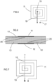
- FIG. 3 shows in section the structure of a transformer 10 according to the invention.
- a transformer comprises two coils 11, 12 superposed and respectively connected to the primary 1 and secondary 21 circuits of the rail sensor. They are thus also called primary coil 11 and secondary coil 12. These two primary 11 and secondary 12 coils are separated by a flat insulating element 13, for example made of plastic material.
- a coil receives an electric current, it generates a magnetic field which generates an induced electric current in the second coil.
- the two primary 1 and secondary 21 circuits are thus interconnected via the coils 11, 12 which communicate without contact, while being electrically insulated by the intermediate insulating element 13.
- the insulating element corresponds to the printed circuit of the rail sensor, on which the other electronic components of the device are arranged, and the transformer 10 is simply obtained by arranging two coils 11, 12 superimposed on each opposite face of the printed circuit. To ensure isolation, there are no through holes in the circuit board at the coils.
- THE figures 4a and 4b respectively represent the two primary 11 and secondary 12 coils, respectively connected to the primary 1 and secondary 21 circuits of the rail sensor.
- Each coil 11, 12 is in the form of a circular winding, having a central end, respectively 15, 14, and a peripheral end respectively 17, 16.
- the two ends of each coil 11, 12 are naturally connected to the electrical circuit of the primary circuit 1 and secondary circuit 21 respectively to form a closed electrical circuit.
- the two coils could have a non-circular shape, for example square, as shown in the figure 5 , or ellipsoidal or rectangular.
- the two coils are preferably identical, have the same shape and the same dimensions. As a variant, they could have a different number of turns. They are for example obtained by copper coils, the number and dimensions of which depend on the intended application.
- each coil 12, 11 is therefore connected to the electrical circuit as mentioned previously. However, this electrical connection is obtained without electrical contact with the various windings of the coil.
- the solution consists in using a wire 18, 19 welded to the central end 14, 15 of each coil 12, 11, and extending beyond the winding of each coil in isolation from this winding, to connect its central terminal to the rest of the electrical circuit. This solution is illustrated on the figure 4 And 5 .
- THE figures 6 and 7 illustrate a first alternative embodiment of the solution described above in which the electrical connection of the central end of the coil is obtained via blind holes 20 and a connecting wire 18, 19 positioned within the thickness of the printed circuit.
- the elements of the previous variant could be reversed, the coils being located within the thickness of the printed circuit and the connecting wires on the surface of the printed circuit and still connected to the coils by blind holes.
- the coreless transformer as described above can be used for different types of exchanges between the primary and secondary circuits. Two main exchanges are advantageously implemented in combination.
- a first exchange consists of a transmission of electrical power from one circuit to the other.
- the power supply of the primary circuit is obtained from the power supply of the secondary circuit, by its power supply terminal 23.
- an electrical connection 3 of the primary circuit 1 is connected to an electrical connection 24 of the secondary circuit, itself connected to the power supply terminal 23, via a transformer 10 as described above. This avoids splitting the power supply to separately supply the two primary and secondary circuits.
- a second exchange consists of a data transmission between the two circuits.
- the primary circuit which first receives the data from the high voltage line, via its direct link 2, carries out a first processing of these data, then transmits them to the secondary circuit, which will carry out a second processing, via a transformer 10 as previously described.
- This data transmission can take place via electrical signals and, for example, frequency modulation.
- the number of turns will be calculated taking into account the fact that the frequency of the control signal will be higher the lower the number of turns.
- the data transmission can be done digitally, the primary circuit comprising a digitization of the data before their transmission by the transformer then operating as a pulse transformer.
- the two parts of the transformer have been called “primary” and “secondary” by convention in the previous description: as the exchanges of energy or data can take place in both directions from one part to the other, the choice of the nomenclature “primary” and “secondary” could have been reversed or variable according to each transformer.
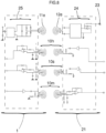
- FIG 8 shows in more detail a measuring device according to the invention, intended for the railway field, for example for measuring on high voltage lines or within a locomotive. It includes a first power supply transformer, as mentioned earlier, and three data transfer transformers, forming four partially independent circuits shown in the figure 8 .
- the transfer of energy takes place from a DC power supply 23 of the secondary circuit, via a circuit 24 comprising in particular a chopper or inverter to transmit an alternating signal to the secondary coil 12e of the power supply transformer.
- This energy is transmitted by this coil to the primary coil 11e which transmits it to the primary circuit via a filter and a rectifier 25.
- a technical problem arises with this solution because the transfer of energy by such a contactless transformer has a relatively low efficiency.
- the solution adopted consists of a simplified primary circuit, comprising only low-power components.
- certain electronic functions are preferably performed at the level of the secondary circuit, the results necessary for the operation of the primary electronic circuit being transferred from the secondary circuit to the primary circuit by a data transformer according to the invention.
- the rail sensor of the figure 8 comprises two other pulse transformers 10h and 10s for respectively transmitting from the secondary circuit to the primary circuit a clock signal and a synchronization signal, for the start of sampling.
- only one of these two transformers could be used.
- the railway sensor includes another 10m pulse transformer to transmit from the primary circuit to the secondary circuit the result of a measurement carried out on the high voltage environment.
- the transformers 10h, 10s and 10m can comprise a reduced number of turns, less than 12, and even advantageously less than 8 for pulse heights to be transmitted of the order of 5V.
- the railway sensor described above could have different embodiments.
- it could comprise another number of transformers, for example for the transfer of additional measurement data, either for a redundancy of the same measurement or for additional measurements. It will advantageously comprise at least three data transfer transformers.
- the transformer according to the invention is advantageously compatible with existing printed circuit structures, made of epoxy material and of standardized thickness of 1.6 mm. Under these conditions, it can achieve dielectric strength greater than 15,000 V and insulation greater than 500 MOhms at 500 V. However, the concept of the invention remains applicable to all other existing printed circuits, with a thickness greater than or equal to 1.6 mm, such as 3.2 mm, or flexible and thin printed circuits. On the other hand, this transformer is provided for operation at a frequency greater than or equal to 1 Mhz.
- the transformer is directly built on a printed circuit, by applying turns directly on or within the printed circuit, by any technique such as by screen printing for example, which avoids having to add an independent transformer, avoids its size and the addition of welds for its fixing.
- the solution then greatly increases the reliability of the transformer obtained since it no longer risks deteriorating in the event of vibrations or temperature changes, which makes it a very efficient solution for an application on board a locomotive or any other vehicle.
- the solution also greatly reduces the cost and size of solutions using a conventional sensor.
Landscapes
- Engineering & Computer Science (AREA)
- Power Engineering (AREA)
- Train Traffic Observation, Control, And Security (AREA)
Claims (15)
- Elektronische Vorrichtung zum Eingreifen in eine elektrische Hochspannungsumgebung,
die Folgendes aufweist:eine gedruckte Schaltung, auf der elektrische Komponenten eines Primärkreises (1) angeordnet sind, der für eine direkte Verbindung mit einer elektrischen Hochspannungsumgebung vorgesehen ist, und eines Sekundärkreises (21),die darüber hinaus mindestens einen Transformator (10) aufweist, der eine Primärspule (11) aufweist, die elektrisch mit dem Primärkreis (1) verbunden ist, und eine Sekundärspule (12), die elektrisch mit dem Sekundärkreis (21) verbunden ist, wobei die zwei Spulen (11, 12) auf jeder Seite der gedruckten Schaltung einander zugewandt positioniert sind und die gedruckte Schaltung ein Isolierelement (13) des Transformators (10) bildet,wobei der Transformator (10) direkt auf der gedruckten Schaltung aufgebaut ist, indem Windungen direkt auf oder innerhalb der gedruckten Schaltung aufgetragen werden, um die Primär- und die Sekundärspule (11, 12) in Form einer flachen Wicklung aus metallischen Windungen zu bilden,dadurch gekennzeichnet, dass jede Spule (11, 12) eine flache Wicklung aus metallischen Windungen aufweist, die ein in der Mitte liegendes Ende (15, 14) aufweist, das mithilfe eines elektrischen Drahts (19, 18), der in der Dicke des Isolierelements (13) positioniert ist und mit dem in der Mitte liegenden Ende (15, 14) der Wicklung verbunden ist, die auf der Oberfläche des Isolierelements angeordnet ist, und über die Wicklung hinaus mithilfe von Sacklöchern (20) in dem Isolierelement (13) elektrisch verbunden ist. - Elektronische Vorrichtung nach Anspruch 1, dadurch gekennzeichnet, dass der Transformator mit einer einzigen gedruckten Schaltung aufgebaut ist, die sein Isolierelement bildet.
- Elektronische Vorrichtung nach einem der vorhergehenden Ansprüche, dadurch gekennzeichnet, dass die Primär- und die Sekundärspule (11, 12) auf jeder der beiden gegenüberliegenden Flächen des Isolierelements (13) übereinander positioniert sind.
- Elektronische Vorrichtung nach einem der vorhergehenden Ansprüche, dadurch gekennzeichnet, dass die beiden Spulen (11, 12) identisch sind.
- Elektronische Vorrichtung nach einem der vorhergehenden Ansprüche, dadurch gekennzeichnet, dass die beiden Spulen (11, 12) eine kreisförmige, ellipsenförmige, quadratische oder rechteckige Form aufweisen und/oder in Form einer flexiblen oder starren Kunststoffplatte vorliegen.
- Elektronische Vorrichtung nach einem der vorhergehenden Ansprüche, dadurch gekennzeichnet, dass jede Spule weniger als 40 Windungen hat.
- Elektronische Vorrichtung nach einem der vorhergehenden Ansprüche, dadurch gekennzeichnet, dass der Transformator mit einer Frequenz größer oder gleich 1 MHz arbeitet.
- Elektronische Vorrichtung nach einem der vorhergehenden Ansprüche, dadurch gekennzeichnet, dass sie einen Transformator (10) aufweist, dessen Funktion darin besteht, eine elektrische Versorgung vom Sekundärkreis (21) zum Primärkreis (1) zu übertragen.
- Elektronische Vorrichtung nach einem der vorhergehenden Ansprüche, dadurch gekennzeichnet, dass sie mindestens einen Transformator (10) aufweist, dessen Funktion darin besteht, Daten vom Primärkreis (1) zum Sekundärkreis (21) auf digitale oder nicht digitale Weise zu übertragen.
- Elektronische Vorrichtung nach einem der vorhergehenden Ansprüche, dadurch gekennzeichnet, dass sie ein Sensor zur Messung der elektrischen Eigenschaften im Eisenbahnbereich ist.
- Elektronische Vorrichtung nach dem vorhergehenden Anspruch, dadurch gekennzeichnet, dass sie mehrere Transformatoren aufweist, darunter mindestens einen Transformator zum Übertragen von Messdaten vom Primärkreis (1) zum Sekundärkreis (21) und einen Transformator zum Übertragen eines Taktsignals vom Sekundärkreis (21) zum Primärkreis (1) und/oder einen Transformator zum Übertragen eines Synchronisationssignals vom Sekundärkreis (21) zum Primärkreis (1) und einen Transformator zum Übertragen einer elektrischen Versorgung vom Sekundärkreis zum Primärkreis.
- Elektronische Vorrichtung nach dem vorhergehenden Anspruch, dadurch gekennzeichnet, dass sie einen Transformator zum Übertragen von Messdaten vom Primärkreis (1) zum Sekundärkreis (21) und/oder einen Transformator zum Übertragen eines Taktsignals vom Sekundärkreis (21) zum Primärkreis (1) und/oder einen Transformator zum Übertragen eines Synchronisationssignals vom Sekundärkreis (21) zum Primärkreis (1) aufweist, wobei mindestens einer dieser Transformatoren eine Anzahl von Windungen von weniger als 12 aufweist.
- Elektronische Vorrichtung nach einem der vorhergehenden Ansprüche, dadurch gekennzeichnet, dass das Isolierelement (13) eine Durchschlagfestigkeit von mehr als 15.000 V und eine Isolation von mehr als 500 MOhm bei 500 V aufweist.
- Elektronische Vorrichtung nach einem der vorhergehenden Ansprüche, dadurch gekennzeichnet, dass das Isolierelement (13) eine Dicke von mindestens 1,6 mm aufweist.
- Elektronische Vorrichtung nach dem vorhergehenden Anspruch, dadurch gekennzeichnet, dass das Isolierelement (13) eine Dicke von weniger als 4 mm aufweist.
Applications Claiming Priority (1)
| Application Number | Priority Date | Filing Date | Title |
|---|---|---|---|
| FR1050405A FR2955422B1 (fr) | 2010-01-21 | 2010-01-21 | Transformateur sans noyau a haute isolation galvanique |
Publications (3)
| Publication Number | Publication Date |
|---|---|
| EP2348516A1 EP2348516A1 (de) | 2011-07-27 |
| EP2348516B1 EP2348516B1 (de) | 2020-09-16 |
| EP2348516B2 true EP2348516B2 (de) | 2023-07-26 |
Family
ID=42480139
Family Applications (1)
| Application Number | Title | Priority Date | Filing Date |
|---|---|---|---|
| EP11151262.0A Active EP2348516B2 (de) | 2010-01-21 | 2011-01-18 | Eisenbahnsensor mit einem kernlosen Transformator mit höher galvanischer Trennung |
Country Status (2)
| Country | Link |
|---|---|
| EP (1) | EP2348516B2 (de) |
| FR (1) | FR2955422B1 (de) |
Families Citing this family (1)
| Publication number | Priority date | Publication date | Assignee | Title |
|---|---|---|---|---|
| WO2025136358A1 (en) * | 2023-12-19 | 2025-06-26 | Power Integrations, Inc. | Communication link on a flexible substrate |
Citations (3)
| Publication number | Priority date | Publication date | Assignee | Title |
|---|---|---|---|---|
| JPH08306540A (ja) † | 1995-05-01 | 1996-11-22 | Murata Mfg Co Ltd | プレーナ空芯トランス |
| US20060039169A1 (en) † | 2004-08-20 | 2006-02-23 | Analog Devices | Power and information signal transfer using micro-transformers |
| US20080179963A1 (en) † | 2006-08-28 | 2008-07-31 | Avago Technologies Ecbu (Singapore) Pte. Ltd. | Galvanic Isolators and Coil Transducers |
Family Cites Families (6)
| Publication number | Priority date | Publication date | Assignee | Title |
|---|---|---|---|---|
| EP0491214A1 (de) * | 1990-12-19 | 1992-06-24 | Asea Brown Boveri Ag | Transformator, insbesondere Impulstransformator |
| US6888438B2 (en) * | 2001-06-15 | 2005-05-03 | City University Of Hong Kong | Planar printed circuit-board transformers with effective electromagnetic interference (EMI) shielding |
| US20030008619A1 (en) * | 2001-07-03 | 2003-01-09 | Werner Raymond J. | Location-based information service for identifying areas with degraded radio signal strength |
| US7123117B2 (en) * | 2003-05-21 | 2006-10-17 | Bel-Fuse Inc. | LAN magnetic interface circuit |
| US20080278275A1 (en) * | 2007-05-10 | 2008-11-13 | Fouquet Julie E | Miniature Transformers Adapted for use in Galvanic Isolators and the Like |
| GB0618647D0 (en) * | 2006-09-21 | 2006-11-01 | Univ City Hong Kong | Semiconductor transformers |
-
2010
- 2010-01-21 FR FR1050405A patent/FR2955422B1/fr not_active Expired - Fee Related
-
2011
- 2011-01-18 EP EP11151262.0A patent/EP2348516B2/de active Active
Patent Citations (3)
| Publication number | Priority date | Publication date | Assignee | Title |
|---|---|---|---|---|
| JPH08306540A (ja) † | 1995-05-01 | 1996-11-22 | Murata Mfg Co Ltd | プレーナ空芯トランス |
| US20060039169A1 (en) † | 2004-08-20 | 2006-02-23 | Analog Devices | Power and information signal transfer using micro-transformers |
| US20080179963A1 (en) † | 2006-08-28 | 2008-07-31 | Avago Technologies Ecbu (Singapore) Pte. Ltd. | Galvanic Isolators and Coil Transducers |
Also Published As
| Publication number | Publication date |
|---|---|
| FR2955422B1 (fr) | 2017-03-17 |
| EP2348516A1 (de) | 2011-07-27 |
| FR2955422A1 (fr) | 2011-07-22 |
| EP2348516B1 (de) | 2020-09-16 |
Similar Documents
| Publication | Publication Date | Title |
|---|---|---|
| EP2801245B1 (de) | Vorrichtung zur montage von kondensatoren für einen elektronischen wandler | |
| WO2008105199A1 (ja) | 分波器及びその製造方法 | |
| EP2398090A3 (de) | Anschluss für ein Batteriepack, Batteriepack mit dem Anschluss und Verfahren zur Herstellung eines Batteriepacks | |
| FR2996072A1 (fr) | Ensemble de connexion electrique pour moteur sans balai | |
| FR2990314A1 (fr) | Dispositif microelectronique de transmission sans fil | |
| EP2076942A2 (de) | Verbindungsvorrichtung für lan | |
| EP3304432A1 (de) | Hochfrequenzantennenschaltung mit ineinandergreifenden gegenseitigen induktoren | |
| FR2553209A1 (fr) | Procede et dispositif de traitement de carte a circuit integre, et carte a circuit integre adaptee a ce traitement | |
| WO2008012416A2 (fr) | Entite electronique a microcircuit | |
| FR2679374A1 (fr) | Bobinage de transformateur constitue d'un ruban isolant comportant des motifs electriquement conducteurs. | |
| EP3035439B1 (de) | Antenne für elektronische vorrichtung | |
| EP1445618B1 (de) | Vorrichtung zur Messung des fliessenden elektrischen Stromes | |
| FR2886467A1 (fr) | Entite electronique a antenne magnetique | |
| EP2182473B1 (de) | Elektronische Vorrichtung, die kontaktlose Kommunikationen im Nahfeld autorisiert | |
| EP2348516B1 (de) | Eisenbahnsensor mit einem kernlosen Transformator mit höher galvanischer Trennung | |
| EP2773010A1 (de) | Elektrischer Generator, Stromversorgungseinrichtung, Sensoranordnung mit einer solchen Stromversorgungseinrichtung | |
| FR2962601A1 (fr) | Connecteur d'ensembles electroniques blindant et sans soudure electrique | |
| FR3013152A1 (fr) | Antenne double face pour carte a puce | |
| FR2916601A1 (fr) | Perfectionnement a l'empreinte de report d'un connecteur sur une carte imprimee. | |
| EP0707215A2 (de) | Separate Übertragung von Daten und Energie für Messinstrument | |
| EP1659413B1 (de) | Trenntransformator | |
| EP2688137B1 (de) | Hyperfrequenzresonator mit Impedanzsprung, insbesondere für Hyperfrequenz-Bandsperrfilter oder -Bandpassfilter | |
| EP2471028B1 (de) | Herstellungsverfahren für eine vorrichtung mit einer rfid-schaltung,und entsprechende vorrichtung | |
| EP3391461A1 (de) | Drahtloskommunikationsmodul, platte zur verwendung bei der herstellung des besagten moduls und verfahren zur herstellung des besagten moduls | |
| WO2007018249A3 (en) | Tubular fuel cell with integrated electrically conducting spacer and fuel cell module |
Legal Events
| Date | Code | Title | Description |
|---|---|---|---|
| PUAI | Public reference made under article 153(3) epc to a published international application that has entered the european phase |
Free format text: ORIGINAL CODE: 0009012 |
|
| AK | Designated contracting states |
Kind code of ref document: A1 Designated state(s): AL AT BE BG CH CY CZ DE DK EE ES FI FR GB GR HR HU IE IS IT LI LT LU LV MC MK MT NL NO PL PT RO RS SE SI SK SM TR |
|
| AX | Request for extension of the european patent |
Extension state: BA ME |
|
| 17P | Request for examination filed |
Effective date: 20120125 |
|
| 17Q | First examination report despatched |
Effective date: 20140807 |
|
| STAA | Information on the status of an ep patent application or granted ep patent |
Free format text: STATUS: EXAMINATION IS IN PROGRESS |
|
| REG | Reference to a national code |
Ref country code: DE Ref legal event code: R079 Ref document number: 602011068598 Country of ref document: DE Free format text: PREVIOUS MAIN CLASS: H01F0027280000 Ipc: H01F0030080000 |
|
| RIC1 | Information provided on ipc code assigned before grant |
Ipc: H01F 38/14 20060101ALI20200220BHEP Ipc: H01F 5/00 20060101ALI20200220BHEP Ipc: H01F 30/08 20060101AFI20200220BHEP Ipc: H01F 27/28 20060101ALI20200220BHEP |
|
| GRAP | Despatch of communication of intention to grant a patent |
Free format text: ORIGINAL CODE: EPIDOSNIGR1 |
|
| STAA | Information on the status of an ep patent application or granted ep patent |
Free format text: STATUS: GRANT OF PATENT IS INTENDED |
|
| INTG | Intention to grant announced |
Effective date: 20200403 |
|
| GRAS | Grant fee paid |
Free format text: ORIGINAL CODE: EPIDOSNIGR3 |
|
| GRAA | (expected) grant |
Free format text: ORIGINAL CODE: 0009210 |
|
| STAA | Information on the status of an ep patent application or granted ep patent |
Free format text: STATUS: THE PATENT HAS BEEN GRANTED |
|
| AK | Designated contracting states |
Kind code of ref document: B1 Designated state(s): AL AT BE BG CH CY CZ DE DK EE ES FI FR GB GR HR HU IE IS IT LI LT LU LV MC MK MT NL NO PL PT RO RS SE SI SK SM TR |
|
| REG | Reference to a national code |
Ref country code: GB Ref legal event code: FG4D Free format text: NOT ENGLISH |
|
| REG | Reference to a national code |
Ref country code: CH Ref legal event code: EP |
|
| REG | Reference to a national code |
Ref country code: DE Ref legal event code: R096 Ref document number: 602011068598 Country of ref document: DE |
|
| REG | Reference to a national code |
Ref country code: IE Ref legal event code: FG4D Free format text: LANGUAGE OF EP DOCUMENT: FRENCH |
|
| REG | Reference to a national code |
Ref country code: AT Ref legal event code: REF Ref document number: 1314895 Country of ref document: AT Kind code of ref document: T Effective date: 20201015 |
|
| PG25 | Lapsed in a contracting state [announced via postgrant information from national office to epo] |
Ref country code: SE Free format text: LAPSE BECAUSE OF FAILURE TO SUBMIT A TRANSLATION OF THE DESCRIPTION OR TO PAY THE FEE WITHIN THE PRESCRIBED TIME-LIMIT Effective date: 20200916 Ref country code: HR Free format text: LAPSE BECAUSE OF FAILURE TO SUBMIT A TRANSLATION OF THE DESCRIPTION OR TO PAY THE FEE WITHIN THE PRESCRIBED TIME-LIMIT Effective date: 20200916 Ref country code: GR Free format text: LAPSE BECAUSE OF FAILURE TO SUBMIT A TRANSLATION OF THE DESCRIPTION OR TO PAY THE FEE WITHIN THE PRESCRIBED TIME-LIMIT Effective date: 20201217 Ref country code: NO Free format text: LAPSE BECAUSE OF FAILURE TO SUBMIT A TRANSLATION OF THE DESCRIPTION OR TO PAY THE FEE WITHIN THE PRESCRIBED TIME-LIMIT Effective date: 20201216 Ref country code: BG Free format text: LAPSE BECAUSE OF FAILURE TO SUBMIT A TRANSLATION OF THE DESCRIPTION OR TO PAY THE FEE WITHIN THE PRESCRIBED TIME-LIMIT Effective date: 20201216 Ref country code: FI Free format text: LAPSE BECAUSE OF FAILURE TO SUBMIT A TRANSLATION OF THE DESCRIPTION OR TO PAY THE FEE WITHIN THE PRESCRIBED TIME-LIMIT Effective date: 20200916 |
|
| REG | Reference to a national code |
Ref country code: AT Ref legal event code: MK05 Ref document number: 1314895 Country of ref document: AT Kind code of ref document: T Effective date: 20200916 |
|
| REG | Reference to a national code |
Ref country code: NL Ref legal event code: MP Effective date: 20200916 |
|
| PG25 | Lapsed in a contracting state [announced via postgrant information from national office to epo] |
Ref country code: LV Free format text: LAPSE BECAUSE OF FAILURE TO SUBMIT A TRANSLATION OF THE DESCRIPTION OR TO PAY THE FEE WITHIN THE PRESCRIBED TIME-LIMIT Effective date: 20200916 Ref country code: RS Free format text: LAPSE BECAUSE OF FAILURE TO SUBMIT A TRANSLATION OF THE DESCRIPTION OR TO PAY THE FEE WITHIN THE PRESCRIBED TIME-LIMIT Effective date: 20200916 |
|
| REG | Reference to a national code |
Ref country code: LT Ref legal event code: MG4D |
|
| PG25 | Lapsed in a contracting state [announced via postgrant information from national office to epo] |
Ref country code: SM Free format text: LAPSE BECAUSE OF FAILURE TO SUBMIT A TRANSLATION OF THE DESCRIPTION OR TO PAY THE FEE WITHIN THE PRESCRIBED TIME-LIMIT Effective date: 20200916 Ref country code: RO Free format text: LAPSE BECAUSE OF FAILURE TO SUBMIT A TRANSLATION OF THE DESCRIPTION OR TO PAY THE FEE WITHIN THE PRESCRIBED TIME-LIMIT Effective date: 20200916 Ref country code: LT Free format text: LAPSE BECAUSE OF FAILURE TO SUBMIT A TRANSLATION OF THE DESCRIPTION OR TO PAY THE FEE WITHIN THE PRESCRIBED TIME-LIMIT Effective date: 20200916 Ref country code: NL Free format text: LAPSE BECAUSE OF FAILURE TO SUBMIT A TRANSLATION OF THE DESCRIPTION OR TO PAY THE FEE WITHIN THE PRESCRIBED TIME-LIMIT Effective date: 20200916 Ref country code: PT Free format text: LAPSE BECAUSE OF FAILURE TO SUBMIT A TRANSLATION OF THE DESCRIPTION OR TO PAY THE FEE WITHIN THE PRESCRIBED TIME-LIMIT Effective date: 20210118 Ref country code: EE Free format text: LAPSE BECAUSE OF FAILURE TO SUBMIT A TRANSLATION OF THE DESCRIPTION OR TO PAY THE FEE WITHIN THE PRESCRIBED TIME-LIMIT Effective date: 20200916 |
|
| PG25 | Lapsed in a contracting state [announced via postgrant information from national office to epo] |
Ref country code: PL Free format text: LAPSE BECAUSE OF FAILURE TO SUBMIT A TRANSLATION OF THE DESCRIPTION OR TO PAY THE FEE WITHIN THE PRESCRIBED TIME-LIMIT Effective date: 20200916 Ref country code: AL Free format text: LAPSE BECAUSE OF FAILURE TO SUBMIT A TRANSLATION OF THE DESCRIPTION OR TO PAY THE FEE WITHIN THE PRESCRIBED TIME-LIMIT Effective date: 20200916 Ref country code: AT Free format text: LAPSE BECAUSE OF FAILURE TO SUBMIT A TRANSLATION OF THE DESCRIPTION OR TO PAY THE FEE WITHIN THE PRESCRIBED TIME-LIMIT Effective date: 20200916 Ref country code: IS Free format text: LAPSE BECAUSE OF FAILURE TO SUBMIT A TRANSLATION OF THE DESCRIPTION OR TO PAY THE FEE WITHIN THE PRESCRIBED TIME-LIMIT Effective date: 20210116 Ref country code: ES Free format text: LAPSE BECAUSE OF FAILURE TO SUBMIT A TRANSLATION OF THE DESCRIPTION OR TO PAY THE FEE WITHIN THE PRESCRIBED TIME-LIMIT Effective date: 20200916 |
|
| REG | Reference to a national code |
Ref country code: DE Ref legal event code: R026 Ref document number: 602011068598 Country of ref document: DE |
|
| PLBI | Opposition filed |
Free format text: ORIGINAL CODE: 0009260 |
|
| PLAX | Notice of opposition and request to file observation + time limit sent |
Free format text: ORIGINAL CODE: EPIDOSNOBS2 |
|
| PG25 | Lapsed in a contracting state [announced via postgrant information from national office to epo] |
Ref country code: SK Free format text: LAPSE BECAUSE OF FAILURE TO SUBMIT A TRANSLATION OF THE DESCRIPTION OR TO PAY THE FEE WITHIN THE PRESCRIBED TIME-LIMIT Effective date: 20200916 |
|
| 26 | Opposition filed |
Opponent name: KNICK ELEKTRONISCHE MESSGERAETE GMBH & CO. KG Effective date: 20210609 |
|
| PG25 | Lapsed in a contracting state [announced via postgrant information from national office to epo] |
Ref country code: SI Free format text: LAPSE BECAUSE OF FAILURE TO SUBMIT A TRANSLATION OF THE DESCRIPTION OR TO PAY THE FEE WITHIN THE PRESCRIBED TIME-LIMIT Effective date: 20200916 Ref country code: MC Free format text: LAPSE BECAUSE OF FAILURE TO SUBMIT A TRANSLATION OF THE DESCRIPTION OR TO PAY THE FEE WITHIN THE PRESCRIBED TIME-LIMIT Effective date: 20200916 Ref country code: DK Free format text: LAPSE BECAUSE OF FAILURE TO SUBMIT A TRANSLATION OF THE DESCRIPTION OR TO PAY THE FEE WITHIN THE PRESCRIBED TIME-LIMIT Effective date: 20200916 |
|
| GBPC | Gb: european patent ceased through non-payment of renewal fee |
Effective date: 20210118 |
|
| PG25 | Lapsed in a contracting state [announced via postgrant information from national office to epo] |
Ref country code: LU Free format text: LAPSE BECAUSE OF NON-PAYMENT OF DUE FEES Effective date: 20210118 |
|
| PLBB | Reply of patent proprietor to notice(s) of opposition received |
Free format text: ORIGINAL CODE: EPIDOSNOBS3 |
|
| PG25 | Lapsed in a contracting state [announced via postgrant information from national office to epo] |
Ref country code: GB Free format text: LAPSE BECAUSE OF NON-PAYMENT OF DUE FEES Effective date: 20210118 |
|
| PG25 | Lapsed in a contracting state [announced via postgrant information from national office to epo] |
Ref country code: IE Free format text: LAPSE BECAUSE OF NON-PAYMENT OF DUE FEES Effective date: 20210118 |
|
| PG25 | Lapsed in a contracting state [announced via postgrant information from national office to epo] |
Ref country code: IS Free format text: LAPSE BECAUSE OF FAILURE TO SUBMIT A TRANSLATION OF THE DESCRIPTION OR TO PAY THE FEE WITHIN THE PRESCRIBED TIME-LIMIT Effective date: 20210116 |
|
| APAH | Appeal reference modified |
Free format text: ORIGINAL CODE: EPIDOSCREFNO |
|
| APBM | Appeal reference recorded |
Free format text: ORIGINAL CODE: EPIDOSNREFNO |
|
| APBP | Date of receipt of notice of appeal recorded |
Free format text: ORIGINAL CODE: EPIDOSNNOA2O |
|
| APBU | Appeal procedure closed |
Free format text: ORIGINAL CODE: EPIDOSNNOA9O |
|
| PG25 | Lapsed in a contracting state [announced via postgrant information from national office to epo] |
Ref country code: HU Free format text: LAPSE BECAUSE OF FAILURE TO SUBMIT A TRANSLATION OF THE DESCRIPTION OR TO PAY THE FEE WITHIN THE PRESCRIBED TIME-LIMIT; INVALID AB INITIO Effective date: 20110118 Ref country code: CY Free format text: LAPSE BECAUSE OF FAILURE TO SUBMIT A TRANSLATION OF THE DESCRIPTION OR TO PAY THE FEE WITHIN THE PRESCRIBED TIME-LIMIT Effective date: 20200916 |
|
| PUAH | Patent maintained in amended form |
Free format text: ORIGINAL CODE: 0009272 |
|
| STAA | Information on the status of an ep patent application or granted ep patent |
Free format text: STATUS: PATENT MAINTAINED AS AMENDED |
|
| 27A | Patent maintained in amended form |
Effective date: 20230726 |
|
| AK | Designated contracting states |
Kind code of ref document: B2 Designated state(s): AL AT BE BG CH CY CZ DE DK EE ES FI FR GB GR HR HU IE IS IT LI LT LU LV MC MK MT NL NO PL PT RO RS SE SI SK SM TR |
|
| REG | Reference to a national code |
Ref country code: DE Ref legal event code: R102 Ref document number: 602011068598 Country of ref document: DE |
|
| PG25 | Lapsed in a contracting state [announced via postgrant information from national office to epo] |
Ref country code: MK Free format text: LAPSE BECAUSE OF FAILURE TO SUBMIT A TRANSLATION OF THE DESCRIPTION OR TO PAY THE FEE WITHIN THE PRESCRIBED TIME-LIMIT Effective date: 20200916 |
|
| PG25 | Lapsed in a contracting state [announced via postgrant information from national office to epo] |
Ref country code: TR Free format text: LAPSE BECAUSE OF FAILURE TO SUBMIT A TRANSLATION OF THE DESCRIPTION OR TO PAY THE FEE WITHIN THE PRESCRIBED TIME-LIMIT Effective date: 20200916 |
|
| PG25 | Lapsed in a contracting state [announced via postgrant information from national office to epo] |
Ref country code: MT Free format text: LAPSE BECAUSE OF FAILURE TO SUBMIT A TRANSLATION OF THE DESCRIPTION OR TO PAY THE FEE WITHIN THE PRESCRIBED TIME-LIMIT Effective date: 20200916 |
|
| REG | Reference to a national code |
Ref country code: CH Ref legal event code: U11 Free format text: ST27 STATUS EVENT CODE: U-0-0-U10-U11 (AS PROVIDED BY THE NATIONAL OFFICE) Effective date: 20260201 |
|
| PGFP | Annual fee paid to national office [announced via postgrant information from national office to epo] |
Ref country code: DE Payment date: 20260114 Year of fee payment: 16 |
|
| PGFP | Annual fee paid to national office [announced via postgrant information from national office to epo] |
Ref country code: BE Payment date: 20260119 Year of fee payment: 16 Ref country code: IT Payment date: 20260107 Year of fee payment: 16 |
|
| PGFP | Annual fee paid to national office [announced via postgrant information from national office to epo] |
Ref country code: FR Payment date: 20260128 Year of fee payment: 16 |
|
| PGFP | Annual fee paid to national office [announced via postgrant information from national office to epo] |
Ref country code: CH Payment date: 20260201 Year of fee payment: 16 Ref country code: CZ Payment date: 20260116 Year of fee payment: 16 |