EP2348340A1 - Ensemble de rétroéclairage disposant de plusieurs plaques de guide lumineux - Google Patents
Ensemble de rétroéclairage disposant de plusieurs plaques de guide lumineux Download PDFInfo
- Publication number
- EP2348340A1 EP2348340A1 EP10014000A EP10014000A EP2348340A1 EP 2348340 A1 EP2348340 A1 EP 2348340A1 EP 10014000 A EP10014000 A EP 10014000A EP 10014000 A EP10014000 A EP 10014000A EP 2348340 A1 EP2348340 A1 EP 2348340A1
- Authority
- EP
- European Patent Office
- Prior art keywords
- light
- backlight assembly
- light emitting
- guide plate
- fixing member
- Prior art date
- Legal status (The legal status is an assumption and is not a legal conclusion. Google has not performed a legal analysis and makes no representation as to the accuracy of the status listed.)
- Withdrawn
Links
- 238000009792 diffusion process Methods 0.000 claims description 30
- 239000000463 material Substances 0.000 claims description 3
- 239000012780 transparent material Substances 0.000 claims 1
- 239000004973 liquid crystal related substance Substances 0.000 description 43
- 238000005286 illumination Methods 0.000 description 10
- 230000003287 optical effect Effects 0.000 description 9
- 238000009826 distribution Methods 0.000 description 6
- 238000001746 injection moulding Methods 0.000 description 4
- 238000000034 method Methods 0.000 description 4
- 230000008878 coupling Effects 0.000 description 3
- 238000010168 coupling process Methods 0.000 description 3
- 238000005859 coupling reaction Methods 0.000 description 3
- 238000001125 extrusion Methods 0.000 description 3
- 239000004033 plastic Substances 0.000 description 3
- 229920003023 plastic Polymers 0.000 description 3
- 238000003825 pressing Methods 0.000 description 3
- 230000008569 process Effects 0.000 description 3
- 239000000758 substrate Substances 0.000 description 3
- 230000000712 assembly Effects 0.000 description 2
- 238000000429 assembly Methods 0.000 description 2
- 230000008901 benefit Effects 0.000 description 2
- 239000013256 coordination polymer Substances 0.000 description 2
- 239000007769 metal material Substances 0.000 description 2
- 238000012986 modification Methods 0.000 description 2
- 230000004048 modification Effects 0.000 description 2
- 229920003229 poly(methyl methacrylate) Polymers 0.000 description 2
- 239000005020 polyethylene terephthalate Substances 0.000 description 2
- 229920000139 polyethylene terephthalate Polymers 0.000 description 2
- 239000004926 polymethyl methacrylate Substances 0.000 description 2
- 230000004044 response Effects 0.000 description 2
- 239000004065 semiconductor Substances 0.000 description 2
- 239000000853 adhesive Substances 0.000 description 1
- 230000001070 adhesive effect Effects 0.000 description 1
- 239000002390 adhesive tape Substances 0.000 description 1
- 230000007423 decrease Effects 0.000 description 1
- 230000003247 decreasing effect Effects 0.000 description 1
- 230000007812 deficiency Effects 0.000 description 1
- 230000005484 gravity Effects 0.000 description 1
- 230000001788 irregular Effects 0.000 description 1
- 238000004519 manufacturing process Methods 0.000 description 1
- 229920000642 polymer Polymers 0.000 description 1
Images


Classifications
-
- G—PHYSICS
- G02—OPTICS
- G02B—OPTICAL ELEMENTS, SYSTEMS OR APPARATUS
- G02B6/00—Light guides; Structural details of arrangements comprising light guides and other optical elements, e.g. couplings
- G02B6/0001—Light guides; Structural details of arrangements comprising light guides and other optical elements, e.g. couplings specially adapted for lighting devices or systems
- G02B6/0011—Light guides; Structural details of arrangements comprising light guides and other optical elements, e.g. couplings specially adapted for lighting devices or systems the light guides being planar or of plate-like form
- G02B6/0075—Arrangements of multiple light guides
- G02B6/0078—Side-by-side arrangements, e.g. for large area displays
- G02B6/008—Side-by-side arrangements, e.g. for large area displays of the partially overlapping type
-
- G—PHYSICS
- G02—OPTICS
- G02F—OPTICAL DEVICES OR ARRANGEMENTS FOR THE CONTROL OF LIGHT BY MODIFICATION OF THE OPTICAL PROPERTIES OF THE MEDIA OF THE ELEMENTS INVOLVED THEREIN; NON-LINEAR OPTICS; FREQUENCY-CHANGING OF LIGHT; OPTICAL LOGIC ELEMENTS; OPTICAL ANALOGUE/DIGITAL CONVERTERS
- G02F1/00—Devices or arrangements for the control of the intensity, colour, phase, polarisation or direction of light arriving from an independent light source, e.g. switching, gating or modulating; Non-linear optics
- G02F1/01—Devices or arrangements for the control of the intensity, colour, phase, polarisation or direction of light arriving from an independent light source, e.g. switching, gating or modulating; Non-linear optics for the control of the intensity, phase, polarisation or colour
- G02F1/13—Devices or arrangements for the control of the intensity, colour, phase, polarisation or direction of light arriving from an independent light source, e.g. switching, gating or modulating; Non-linear optics for the control of the intensity, phase, polarisation or colour based on liquid crystals, e.g. single liquid crystal display cells
- G02F1/133—Constructional arrangements; Operation of liquid crystal cells; Circuit arrangements
- G02F1/1333—Constructional arrangements; Manufacturing methods
- G02F1/1335—Structural association of cells with optical devices, e.g. polarisers or reflectors
- G02F1/1336—Illuminating devices
-
- G—PHYSICS
- G02—OPTICS
- G02B—OPTICAL ELEMENTS, SYSTEMS OR APPARATUS
- G02B6/00—Light guides; Structural details of arrangements comprising light guides and other optical elements, e.g. couplings
- G02B6/0001—Light guides; Structural details of arrangements comprising light guides and other optical elements, e.g. couplings specially adapted for lighting devices or systems
- G02B6/0011—Light guides; Structural details of arrangements comprising light guides and other optical elements, e.g. couplings specially adapted for lighting devices or systems the light guides being planar or of plate-like form
- G02B6/0081—Mechanical or electrical aspects of the light guide and light source in the lighting device peculiar to the adaptation to planar light guides, e.g. concerning packaging
-
- G—PHYSICS
- G02—OPTICS
- G02F—OPTICAL DEVICES OR ARRANGEMENTS FOR THE CONTROL OF LIGHT BY MODIFICATION OF THE OPTICAL PROPERTIES OF THE MEDIA OF THE ELEMENTS INVOLVED THEREIN; NON-LINEAR OPTICS; FREQUENCY-CHANGING OF LIGHT; OPTICAL LOGIC ELEMENTS; OPTICAL ANALOGUE/DIGITAL CONVERTERS
- G02F1/00—Devices or arrangements for the control of the intensity, colour, phase, polarisation or direction of light arriving from an independent light source, e.g. switching, gating or modulating; Non-linear optics
- G02F1/01—Devices or arrangements for the control of the intensity, colour, phase, polarisation or direction of light arriving from an independent light source, e.g. switching, gating or modulating; Non-linear optics for the control of the intensity, phase, polarisation or colour
- G02F1/13—Devices or arrangements for the control of the intensity, colour, phase, polarisation or direction of light arriving from an independent light source, e.g. switching, gating or modulating; Non-linear optics for the control of the intensity, phase, polarisation or colour based on liquid crystals, e.g. single liquid crystal display cells
- G02F1/133—Constructional arrangements; Operation of liquid crystal cells; Circuit arrangements
- G02F1/1333—Constructional arrangements; Manufacturing methods
- G02F1/1335—Structural association of cells with optical devices, e.g. polarisers or reflectors
- G02F1/1336—Illuminating devices
- G02F1/133602—Direct backlight
- G02F1/133608—Direct backlight including particular frames or supporting means
Definitions
- Exemplary embodiments of the present invention relate to a backlight assembly having a plurality of light guide plates. More particularly, exemplary embodiments of the present invention relate to a backlight assembly capable of preventing movement of the light guide plate to improve display quality of the display apparatus.
- a liquid crystal display includes a liquid crystal panel that displays an image and a backlight assembly that provides light to the liquid crystal panel.
- the liquid crystal panel includes two transparent substrates and a liquid crystal layer disposed between the two substrates to display the image in response to a variation in the arrangement of liquid crystal molecules of the liquid crystal layer caused by an electric signal.
- the backlight assembly is classified as a direct-illumination type backlight assembly or an edge-illumination type backlight assembly according to the position of the light source.
- the direct-illumination type backlight assembly has a plurality of light sources located in a region overlapping the liquid crystal panel. However, since a distance between the liquid crystal panel and the light sources is required to uniformly provide light to the liquid crystal panel, the liquid crystal display increases in thickness.
- the light sources are disposed outside the liquid crystal panel while not overlapping the liquid crystal panel in a plan view, and a light guide plate having a constant thickness is used to uniformly provide the liquid crystal panel with light from an exterior. Since light emitted from the light sources is provided to the liquid crystal panel after passing through the light guide plate, brightness in the liquid crystal panel is decreased. In addition, the liquid crystal display is heavier due to the light guide plate.
- the hybrid-type backlight assembly includes a plurality of light emitting units each of which includes a light source that emits light and a light guide plate that receives light from the light source.
- the light emitting units are disposed under the liquid crystal panel such that each of the light emitting units partially overlaps an adjacent light emitting unit.
- a distance between the liquid crystal panel and the light emitting units is reduced, thereby increasing brightness of the liquid crystal display.
- the light source and the light guide plate may shift from their original positions. Due to the movement of the light source and the light guide plate, damage to the liquid crystal display may occur.
- Exemplary embodiments of the present invention provide a backlight assembly capable of securely holding a light emitting unit to improve its reliability.
- An exemplary embodiment of the present invention discloses a backlight assembly comprising a plurality of light emitting units arranged adjacent to each other to provide a light to a display panel, and a lower container that accommodates the light emitting units, wherein at least one light emitting unit comprises a light source module to emit the light, a light guide plate to guide the light emitted from the light source module to the display panel, and a light source cover covering the light source module, and wherein the light source cover of the at least one light emitting unit comprises a fixing member to fix a light guide plate of an adjacent light emitting unit.
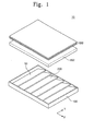
- FIG. 1 is an exploded perspective view showing a backlight assembly including a plurality of light emitting units according to exemplary embodiments of the present invention.
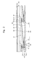
- FIG. 2 is a sectional view showing an assembled structure of the backlight assembly including the light emitting units of FIG. 1 .
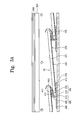
- FIG. 3A is a sectional view showing a structure of the backlight assembly wherein a light facing portion of each of the light emitting units is covered by a fixing member.
- FIG. 3B is a sectional view showing a structure of the backlight assembly wherein the fixing member of FIG. 3A is pressed and fixed by a light diffusion plate.
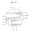
- FIG. 3C is an enlarged view showing portion "A" of FIG. 3B to illustrate a connection between a light guide plate and a light source cover according to the fixing member.
- FIG. 4A , FIG. 4B , and FIG. 4C are plan views showing the backlight assembly including the light guide plate that is fixed by the fixing member according to exemplary embodiments of the present invention.
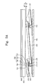
- FIG. 5A is a sectional view showing a structure of the backlight assembly wherein a protruded fixing portion formed on the light source cover fixes an adjacent light facing portion.
- FIG. 5B is a plan view showing a structure wherein the protruded fixing portion of FIG. 5A fixes the light guide plate.
- FIG. 6A , FIG. 6B, and FIG. 6C are sectional views showing various protruded fixing members according to exemplary embodiments of the present invention.
- FIG. 7 is a sectional view showing a structure of the backlight assembly wherein a light guiding portion of the light guide plate is supported and fixed by a light guide plate supporting portion formed on a lower container and an engaging member.
- FIG. 8 is an exploded perspective view showing a liquid crystal display to which a light guide plate fixing structure is applied according to exemplary embodiments of the present invention.
- first, second, etc. may be used herein to describe various elements, components, regions, layers and/or sections, these elements, components, regions, layers and/or sections should not be limited by these terms. These terms are only used to distinguish one element, component, region, layer or section from another region, layer or section. Thus, a first element, component, region, layer or section discussed below could be termed a second element, component, region, layer or section without departing from the teachings of the present invention.
- spatially relative terms such as “beneath”, “below”, “lower”, “above”, “upper” and the like, may be used herein for ease of description to describe one element or feature's relationship to another element(s) or feature(s) as illustrated in the figures. It will be understood that the spatially relative terms are intended to encompass different orientations of the device in use or operation in addition to the orientation depicted in the figures. For example, if the device in the figures is turned over, elements described as “below” or “beneath” other elements or features would then be oriented “above” the other elements or features. Thus, the exemplary term “below” can encompass both an orientation of above and below. The device may be otherwise oriented (rotated 90 degrees or at other orientations) and the spatially relative descriptors used herein interpreted accordingly.
- FIG. 1 is an exploded perspective view showing a backlight assembly including a plurality of light emitting units according to exemplary embodiments of the present invention.
- a backlight assembly 10 includes a plurality of light emitting units 50.
- Each light emitting unit 50 has the structure of an edge-illumination type backlight assembly.
- each light emitting unit 50 includes a light guide plate 200 and a light source module (not shown) arranged adjacent to the light guide plate 200 and emits a light in response to the supply of power voltage from an exterior.
- the light emitting units 50 have the same structure, but the structure of the backlight assembly 10 should not be limited thereto or thereby. That is, although not shown in FIG. 1 , the structure of the light emitting units 50 may be selectively applied to one or some of the light emitting units 50, and the other light emitting units 50 may have a different structure.
- the light emitting units 50 are connected with each other in series in an x-direction.
- a light source module of each of the light emitting units 50 overlaps the light guide plate 200 of an adjacent light emitting unit 50 in a plan view.
- the light emitting units 50 are connected with each other in series in one direction and connected with each other in parallel in another direction.
- the light emitting units 50 may be connected with each other in series in the x-direction and connected with each other in parallel in a y-direction substantially perpendicular to the x-direction, so that the light emitting units 50 may be arranged in a two-dimensional array.
- the light emitting units arranged in the two-dimensional array may be driven independently to emit the light, a backlight local dimming method in which the brightness of the liquid crystal display is partially controlled after analyzing images displayed on the liquid crystal display may be easily applied to the liquid crystal display.
- the light emitting units 50 are arranged at positions overlapping the liquid crystal panel (not shown), so that the backlight assembly 10 may serve as a direct-illumination type backlight assembly.
- the backlight assembly 10 according to the present exemplary embodiment has structural characteristics of the edge-illumination type backlight assembly and the direct-illumination type backlight assembly to form a hybrid-type backlight assembly.
- the hybrid-type backlight assembly may be called a tiled-type backlight assembly.
- a diffusion plate 800 and an optical sheet 850 are disposed on the light emitting units 50.
- the diffusion plate 800 diffuses the light emitted from the light emitting units 50 to improve uniformity of the light.
- the optical sheet 850 may include various optical sheets, such as a diffusion sheet, a light collection sheet, etc., and have various combinations of those sheets to provide light distribution characteristics required for the liquid crystal display.
- the light emitting units 50, the diffusion plate 800, and the optical sheet 850 are accommodated in a lower container 100.
- the lower container 100 determines an external shape of the backlight assembly 10 and the liquid crystal display, blocks external impact to the backlight assembly 10 and the liquid crystal display, and transmits heat generated therefrom to the exterior of the lower container 100.
- the lower container 100 is coupled with an upper container (not shown) to accommodate the liquid crystal display.
- the lower container 100 has a rectangular shape in which an accommodating space is defined, but the shape of the lower container 100 should not be limited thereto or thereby. That is, the lower container 100 may have various shapes if the light emitting units 50 may be stably accommodated and the heat generated inside the lower container 100 may be effectively dissipated.
- FIG. 2 is a sectional view showing an assembled structure of the backlight assembly including the light emitting units of FIG. 1 .
- the light emitting units 50 since the light emitting units 50 have the same structure and function, for the convenience of explanation, one or two light emitting units 50 will be described in detail as a representative example.
- each light emitting unit 50 includes a light source module 300, a light source cover 400, and the light guide plate 200.
- the light source module 300 of each light emitting unit 50 overlaps the light guide plate 200 of adjacent light emitting unit 50.
- the light source module 300 includes a light emitting device 310 that converts an electric signal to emit the light and a printed circuit board 320 that provides the electric signal to the light emitting device 310.
- the light source module 300 may utilize various light sources such as a cold cathode fluorescent lamp, a heat cathode fluorescent lamp, an organic light emitting device, an inorganic light emitting device, a light emitting diode, etc. In the present exemplary embodiment, the light emitting diode will be described as an example of the light source module 300, but it should not be limited thereto or thereby.
- the light source module 300 may include the light emitting device 310, which has a light emitting diode package including a semiconductor light emitting device, an insulating package, and an electrode.
- the light emitting device 310 may have a different structure to emit light using the semiconductor light emitting device.
- the light source module 300 further includes the printed circuit board 320 to apply the electric signal to the light emitting device 310.
- a plurality of light emitting devices 310 may be mounted on the printed circuit board 320, and the plurality of light emitting devices 310 may collectively emit the light.
- the printed circuit board 320 drives the light emitting device 310 using a conductive pattern (not shown) and includes a base substrate on which the conductive pattern is formed.
- the light emitting device 310 provides the light to the light guide plate 200 through a light emitting surface 311 of the light emitting device 310.
- the light emitting surface 311 contacts a light incident surface 211 of the light guide plate 200 to improve the light incident efficiency.
- the light guide plate 200 includes a light incident portion 210 provided with the light incident surface 211, a light guiding portion 220 extended from the light incident portion 210, and a light facing portion 230 extended from the light guiding portion 220.
- the light facing portion 230 is provided with a light facing surface 231 which faces the light incident surface 211 of the light incident portion 210.
- the light incident portion 210 is covered by the light source cover 400, and the light incident portion 210 may also be covered by the light facing portion 230 of the light guide plate 200 of adjacent light emitting unit 50.
- the light incident portion 210 is connected with the light guiding portion 220, so that the light that enters through the light incident surface 211 may be transmitted to the light guiding portion 220.
- the light guiding portion 220 may be provided with a predetermined pattern formed thereon or therein to uniformly distribute the light in the light guide plate 200.
- the light guiding portion 220 includes a light exiting surface 221 from which the light exits toward the liquid crystal panel (not shown) and a reflecting surface 222 by which the light is reflected.
- a reflecting sheet 500 may be disposed under the reflecting surface 222. The reflecting sheet 500 is attached to the reflecting surface 222 to allow the light to be uniformly distributed in the light guiding portion 220.
- the light guiding portion 220 is upwardly inclined toward the diffusion plate 800 from the light incident portion 210 adjacent to the light source module 300.
- the light guiding portion 220 is connected with the light facing portion 230.
- the light facing portion 230 includes the light facing surface 231 and overlaps the light source module 300 and the light source cover 400 of adjacent light emitting unit 50. Particularly, the light facing portion 230 is supported by the light source cover 400 of adjacent light emitting unit 50.
- the light incident surface 211 is positioned at a relatively lower position in the backlight assembly
- the light facing surface 231 is positioned at a relatively higher position in the backlight assembly
- the light guiding portion 220 is positioned between the light incident surface 211 and the light facing surface 231.
- the light facing surface 231 is positioned near the diffusion plate 800 and contacts the diffusion plate 800 at a contact point CP.
- the contact point CP may be a point or a regular or irregular line segment.
- the light guide plate 200 may contact or be adjacent to the diffusion plate 800, thereby reducing the thickness of the backlight assembly 10.
- the thickness of the light facing surface 231 may be the same as the light incident surface 211 as shown in FIG. 2 , so that the light guide plate 200 may have a substantially uniform thickness.
- the light guide plate 200 may have a wedge shape in which a thickness of the light guide plate 200 decreases from the light incident surface 211 to the light facing surface 231.
- the light guide plate 200 should be thin.
- the light guide plate 200 having a thickness of a few millimeters, generally, may be formed through an extrusion molding process. Since the light guide plate 200 formed through the extrusion molding process may be provided with a substantially uniform thickness and may have flexibility, the light guiding portion 220 may be flat by shapes of the reflecting sheet 500 and the lower container 100.
- the light guide plate 200 may be formed through an injection molding process, which forms a light guide plate 200 having a thickness greater than the light guide plate 200 formed through the extrusion molding process.
- the injection molding process has an advantage in forming the wedge-type light guide plate.
- the light guide plate 200 may be formed of a transparent polymer such as polymethylmethacrylate (PMMA).
- the light source cover 400 is shaped to surround the light source module 300.
- the light source cover 400 includes an upper cover 410 disposed above the light source module 300, a lower cover 430 disposed below the light source module 300, and a center cover 420 connecting the upper cover 410 and the lower cover 430 and facing the light incident surface 211 of the light guide plate 200.
- the upper cover 410 supports the light facing portion 230 of adjacent light guide plate 200.
- the upper cover 410 is mechanically coupled with the light facing portion 230 of the light guide plate 200 of the adjacent light emitting unit 50.
- the light facing portion 230 of the light guide plate 200 of the adjacent light emitting unit 50 may be simply placed on or adhered to the upper cover 410.
- the lower cover 430 extends from the center cover 420 to the lower portion of a corresponding light emitting unit 50 to support the light incident portion 210 and is fixed to the lower container 100 using a separate device (not shown).
- the lower cover 430 may support the printed circuit board 320 of the light source module 300.
- the light source cover 400 has a substantially U-shape in cross section, but it should not be limited thereto or thereby.
- the lower container 100 accommodates the light emitting units 50 on a main surface 110 thereof.
- the lower cover 430 of each light emitting unit 50 may be directly coupled with the main surface 110 and the center cover 420 of each light emitting unit 50 may be held by a stopper 120.
- FIG. 3A is a sectional view showing a structure of the backlight assembly that a light facing portion of each of the light emitting units is covered by a fixing member.
- the same reference numerals denote the same elements in FIG. 2 , and thus detailed descriptions of the same elements will be omitted.
- a lower container 100 of a backlight assembly 10 accommodates a plurality of light emitting units 50 therein.
- Each light emitting unit 50 includes a light source module 300 emitting a light, a light source cover 400 that covers the light source module 300, a light guide plate 200 that receives the light from the light source module 300 and including a light exiting surface 221 from which the light exits, and a fixing member 600 that surrounds a light facing portion 230 of the light guide plate 200 and that holds the position of the light guide plate 200.
- the light source cover 400 includes an upper cover 410, a center cover 420, and a fixing portion 440.
- the upper cover 410 is disposed on the light source module 300 to cover the light source module 300 in a plan view and support the light facing portion 230 of an adjacent light emitting unit 50.
- the light facing portion 230 is disposed in an inclined manner, so that an upper surface 411 of the upper cover 410 may be inclined to have a steep slop equal to that of the light facing portion 230.
- the upper cover 410 includes a light incident facing surface 413 corresponding to the light incident portion 210 to cover the light incident portion 210 of the light guide plate 200.
- the light incident facing surface 413 may have a steep slope equal to that of the light incident portion 210 and guides the light passing through the light incident portion 210 to the light guiding portion 220.
- the upper cover 410 includes a device-facing surface 415 corresponding to an upper surface of the light emitting device 310. The device-facing surface 415 faces the light emitting device 310 of the light source module 300 and guides the light from the light emitting device 310 to the light incident portion 210.
- the upper cover 410 of the light source cover 400 is connected with the center cover 420.
- the center cover 420 extends vertically downwardly from the upper cover 410 upper cover 410 and is positioned at a rear of the light emitting surface of the light emitting device 310.
- the center cover 420 has a flat shape, but it should not be limited thereto. That is, the center cover 420 may have various shapes if the center cover 420 may connect the upper cover 410 and the fixing portion 440 to cover the light emitting device 310.
- the fixing portion 440 extends from the center cover 420 and fixes the light source cover 400 to the lower container 100. According to FIG.
- the fixing portion 440 extends toward an opposite direction, i.e., to the adjacent light emitting unit 50, of a corresponding light source module 300, so that the thickness of the backlight assembly 10 may be reduced by arranging the lower cover 430 under the light source module 300 as shown in FIG. 2 .
- the fixing portion 440 is placed at a vacant space under the light guiding portion 220 of the light guide plate 200 of the adjacent light emitting unit 50, to thereby reduce the thickness of the backlight assembly 10.
- the light facing portion 230 of the light emitting unit 50 is mounted on the light source cover 400 of the adjacent light emitting unit 50, the light facing surface 230 may be vulnerable to external impact since the light facing portion 230 is not fixed.
- the light facing portion 230 is mechanically coupled with the light source cover 400, thereby improving impact resistance of the light facing portion 230.
- FIGS. 3A and 3B Such structure to improve the impact resistance is shown in FIGS. 3A and 3B .
- the fixing member 600 having a flexible sheet shape is provided to the backlight assembly 10. The fixing member 600 connects the light facing portion 230 of the light guide plate 200 of the corresponding light emitting unit 50 and the light source cover 400 of the adjacent light emitting unit 50.
- FIG. 3B is a sectional view showing a structure of the backlight assembly wherein the fixing member of FIG. 3A is pressed and fixed by a light diffusion plate
- FIG. 3C is an enlarged view showing portion "A" of FIG. 3B to illustrate a connection between a light guide plate and a light source cover according to the fixing member.
- the fixing member 600 connects the light source cover 400 of the corresponding light emitting unit 50 and the light facing portion 230 of the light guide plate 200 of the light emitting unit 50 adjacent to the corresponding light emitting unit 50 .
- the fixing member 600 includes a first fixing portion 610 coupled with an upper surface 233 of the light facing portion 230 of the light guide plate 200 of the adjacent light emitting unit 50, a second fixing portion 620 coupled with the upper cover 410 of the light source cover 400 covering the light source module 300, and a connection portion 630 connecting the first fixing portion 610 and the second fixing portion 620.
- the upper cover 410 includes the light incident facing surface 413 facing the light incident portion 210 of the light guide plate 200, and the second fixing portion 620 is connected with the light incident facing surface 413.
- the first and second fixing portions 610 and 620 may be coupled with the upper surface 233 of the light facing portion 230 and the light incident facing surface 413 with an adhesive member 30 such as a double-sided adhesive tape.
- connection portion 630 may be spaced apart from the light facing surface 231 of the light facing portion 230 by a predetermined distance G.
- the light emitting device 310 in the backlight assembly 10 converts the electrical energy to the light energy, and the remaining part of the electrical energy not converted to the light energy is converted to the thermal energy.
- a portion of the light guide plate 200 adjacent to the light emitting device 310 may be expanded by the thermal energy. This thermal expansion may occur adjacent to the light emitting device 310 that serves as a thermal source.
- the length of the light guide plate 200 may be lengthened.
- the connection portion 630 of the fixing member 600 is located at a position spaced apart from the light facing surface 231 with the distance G as shown in FIG. 3C , the fixing member 600 holds the light guide plate 200 even if the light guide plate 200 is expanded.
- the fixing member 600 connects the light source cover 400 of the corresponding light emitting unit 50 and the light facing portion 230 of the light guide plate of the adjacent light emitting unit 50 to prevent the movement of the light facing portion 230 of the light guide plate 200.
- the light facing portion 230 of the corresponding light emitting unit 50 is coupled with the light source cover 400 of the adjacent light emitting unit 50, and thus the light guide plate 200 may have the impact resistance with respect to external impact applied by manufacturer or user.
- the first fixing portion 610 may be pressed and fixed to the light facing portion 230 of the light guide plate 200 of the adjacent light emitting unit 50 by the diffusion plate 800 provided above the light guide plate 200.
- the diffusion plate 800 may have a thickness greater than the light guide plate 200 and apply a load to the fixing member 600 to prevent the movement of the fixing member 600.
- FIGS. 3A to 3C a structure wherein the diffusion plate 800 presses the fixing member 600 by the force of gravity is been shown, but, in the backlight assembly 10 according to the present exemplary embodiment, movement of the light facing portion 230 of the light guide plate 200 may also be prevented if only the light facing portion 230 is coupled with the light source cover 400 that overlaps the light facing portion 230 by the fixing member 600. Accordingly, the light facing portion 230 of the light guide plate may be spaced apart from the diffusion plate 800 with a predetermined distance.
- the fixing member 600 may reflect the light while fixing the light facing portion 230 of the light guide plate 200.
- the fixing member 600 for the reflection of the light may be a reflection sheet that is formed of polyethyleneterephthalate (PET) coated with a white color.
- PET polyethyleneterephthalate
- the fixing member 600 may be a transparent film in order to minimize negative affects on the optical design of the backlight assembly, which are caused by the fixing member 600.
- the fixing member 600 is the transparent film, the negative affects caused by the fixing member 600 on the light distribution in the light facing portion 230 may be reduced, thereby reducing optical negative affects even though the connection portion 630 of the fixing member 600 covers a portion of the light guiding portion 220 of the light guide plate 200.
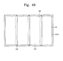
- FIGS. 4A to 4C are plan views showing the backlight assembly including the light guide plate that is fixed by the fixing member according to an exemplary embodiment of the present invention.
- the diffusion plate 800 and the optical sheet 850 disposed on the light guide plate as shown in FIGS. 1 to 3 have been omitted in the backlight assembly of FIGS. 4A to 4C .
- the backlight assembly includes four light emitting units 50.
- Each light emitting unit 50 includes the light source module 300, and the light source module 300 of each light emitting unit 50 is covered by the light facing portion 230 of the adjacent light emitting unit 50 except for a right-side outermost light emitting unit 50 on the right side.
- the light source module 30 of the right-side outermost light emitting unit 50 is covered by an effective light emitting area ELEA of the backlight assembly.
- each light facing portion 230 is covered by the fixing member 600 and extended from a first side of the effective light emitting area ELEA to a second side of the light effective light emitting area ELEA, which is opposite to the first side.
- the fixing member 600 may be extended outside the effective light emitting area ELEA by using an outer fixing portion 650.
- the outer fixing portion 650 may fix the light facing portion 230 of the light guide plate 200 of each light emitting unit 50 without negatively affecting the light distribution of the backlight assembly 10.
- FIG. 4B shows a backlight assembly employing only the outer fixing portion 650 as the fixing member.
- the fixing member is placed outside the effective light emitting area ELEA, thereby minimizing the negative affects caused by the fixing member on the light distribution of the backlight assembly 10.
- FIG. 4C shows a backlight assembly 10 employing the fixing member placed at portions in the effective light emitting area ELEA and outside the effective light emitting area ELEA.
- the fixing member 600 since the fixing member 600 is discontinuously formed in the effective light emitting area ELEA, the negative affects on the light distribution may be reduced. In addition, the fixing member 600 may effectively fix the light facing portion 230 of each light emitting unit 50 together with the outer fixing portion 650.
- the arrangement and distribution of the fixing member shown in FIGS. 4A to 4C may be applied to the backlight assembly shown in FIGS. 3A to 3C , but this may be applied to backlight assemblies that will be described later.
- FIG. 5A is a sectional view showing a structure of the backlight assembly wherein a protruded fixing portion formed on the light source cover 400 fixes an adjacent light facing portion.
- the upper cover 410 of the light source cover 400 is provided with a protruding fixing member 700 formed thereon.
- a lower portion 710 of the protruding fixing member 700 is attached to the upper surface 411 of the upper cover 410.
- a body portion 720 extends from the lower portion 710 of protruding fixing part 700 and a lid 730 is formed at the end of the body portion 720.
- the body portion 720 passes through a fixing hole 240 formed through the light guide plate 200 and the lid 730 makes contact with the upper surface 233 of the light facing portion 230 to prevent the light guide plate 200 from being separated from the protruding fixing member 700.
- the lid 730 has a cross-sectional area wider than that of the body portion 720.
- the upper surface 233 of the light facing portion contacts a first surface 731 of the lid 730.
- a second surface 733 opposite to the first surface 731 of the lid 730 contacts the diffusion plate 800. That is, the first surface 731 of the lid 730 faces the light guide plate 200 and the second surface 733 faces the liquid crystal panel.
- FIG. 5A a structure wherein the light guide plate 200 is provided with the fixing hole 240 to accommodate the body portion 720 is shown, but the structure of the light guide plate 200 to accommodate the body portion 720 should not be limited to the fixing hole 240. That is, in case that the protruding fixing member 700 does not have a lid 730, a fixing recess that does not penetrate the light guide plate 200 may be formed in the light guide plate 200 instead of forming the fixing hole 240. In exemplary embodiments that will be described below, the fixing recess may be formed instead of the fixing hole in the structure that the lid 730 is not included in the protruding fixing member 700.
- the lid 730 of the protruding fixing member 700 has a predetermined thickness t1. Due to the thickness t1, the light facing portion 230 of the light guide plate does contact the diffusion plate 800. That is, the light facing portion 230 is spaced apart from the diffusion plate 800 by a predetermined distance t2. Thus, although the light guide plate 200 is expanded in its longitudinal direction due to the light emitted from the light emitting device 310, the light facing surface 231 of the light facing portion 230 does not contact the diffusion plate 800. Since the diffusion plate 800 is supported by the lid 730 of the protruding fixing member 700, the light guide plate 200 may be prevented from moving without the support by the light facing portion 230 of the light guide plate 200.
- the protruding fixing member 700 may be formed of a plastic material, and the light source cover 400 to which the protruding fixing member 700 is coupled may be formed of a plastic or metal material. In the case that the light source cover 400 is formed of the metal material, the heat generated from the light emitting device 310 may be effectively dissipated through the lower container 100.
- the protruding fixing member 700 is coupled with the light source cover 400 through a manufacturing process such as an insert injection molding method. In the insert injection molding method, the upper cover 410 of the light source cover 400 may be positioned at the substantially same level as the lower portion 710 of the protruding fixing member 700.
- the protruding fixing member 700 may be integrally formed with the light source cover 400, so that the lower portion 710 of the protruding fixing member 700 may be the same member as the upper cover 410 of the light source cover 400.
- FIG. 5B is a plan view showing a structure wherein the protruded fixing member 700 of FIG. 5A fixes the light guide plate 200.
- the diffusion plate and the optical sheet of the backlight assembly will be omitted.
- the lid 730 of the protruding fixing member 700 has a straight recess 735.
- One or a plurality of the straight recess 735 may be provided in the lid.
- the outer surface 737 of the lid 730 is pressed toward a center of the lid 730, the outer surface 737 moves to the center of the lid 730. Then, the outer surface 737 returns its original position when the pressing force applied to the outer surface 737 is removed.
- the width of the lid 730 becomes smaller than the width of the fixing hole 240 formed through the light guide plate while pressing the outer surface 737, so that the lid 730 may pass through the fixing hole 240. After that, the pressing force is removed and the lid 730 is positioned on the upper surface of the light facing surface 231 corresponding to the fixing hole 240
- the fixing hole 240 formed through the light guide plate 200 has an oval shape having a longer axis corresponding to a longitudinal direction (x) of the light guide plate 200 when viewed in a plan view.
- the fixing member 240 may have various shapes, the axis of the fixing hole 240 corresponding to the longitudinal direction (x) is longer than an axis of the fixing hole 240 corresponding to a direction (y) substantially perpendicular to the longitudinal direction (x). That is, the fixing hole 240 has a length (b) corresponding to the longitudinal direction (x) greater than the width (c) of the lid 730.
- a length (a) of the fixing hole 240 corresponding to the direction (y) perpendicular to the longitudinal direction (x) is shorter than the width (c) of the lid 730.
- the lid 730 may hold the light guide plate 200, so that the light guide plate 200 may maintain its position even if the light guide plate 200 expands due to temperature.
- FIGS. 6A to 6C are sectional views showing various protruded fixing members according to an exemplary embodiment of the present invention.
- the protruding fixing member 700 has a shape obtained by removing the lid 730 of the protruding fixing member 700.
- An uppermost surface 740 of the protruding fixing member 700 is flat and provided at a lower position than the upper surface 233 of the light facing portion 230 of the light guide plate 200. If the protruding fixing member 700 is transparent, the concentration of the light in the protruding fixing member 700 becomes weak, and if the protruding fixing member 700 is opaque, dark-area phenomenon caused by the protruding fixing member 700 may be prevented.
- an uppermost surface 740 of the protruding fixing member 700 is provided at a position higher than the upper surface 233 of the light facing portion 230 of the light guide plate 200.
- the uppermost surface 740 may contact the diffusion plate 800 and support the diffusion plate 800 together with the body portion 720 of the protruding fixing member 700.
- the uppermost surface 740 has a cross-sectional area smaller than that of the body portion 720 in a plan view, the light concentration in the protruding fixing member 700 may be prevented from appearing through the diffusion plate 800. If the protruding fixing member 700 is opaque, the dark-area phenomenon appearing on the diffusion plate may be prevented.
- a protrusion 750 is formed on the lid 730 of the protruding fixing member 700 shown in FIGS. 5A and 5B .
- the protrusion 750 may support the diffusion plate 800 and have a relatively smaller cross-sectional area, so that the protruding fixing member 700 may be prevented from being recognized outside the backlight assembly 10.
- the protruding fixing members 700 shown in FIGS. 5A to 5C and 6A to 6C may be distributed the same as the fixing member 600 shown in FIGS. 4B and 4C .
- the outer fixing portion 650 is formed in the backlight assembly 10
- display quality of the backlight assembly may be easily improved since the light facing portion 230 of the light guide plate 200 of each light emitting unit 50 is fixed by the fixing member provided outside the effective light emitting area ELEA.
- the fixing member 600 is formed in the effective light emitting area ELEA, inconsistency in brightness caused by sag of the diffusion plate 800 may be prevented since the protruding fixing member 700 supports the diffusion plate 800.
- FIG. 7 is a sectional view showing a structure of the backlight assembly wherein a light guiding portion of the light guide plate is supported and fixed by a light guide plate supporting portion formed on a lower container and an engaging member.
- a light guide plate supporting member 150 is disposed in a lower space 280 between the lower container 100 and the light guide plate 200.
- the light guide plate supporting member 150 is fixed to the main surface 110 of the lower container 100 to support the reflecting sheet 500 that contacts the reflecting surface of the light guide plate 200 and to support the light guiding portion 220 of the light guide plate 200.
- the light guide plate supporting member 150 is coupled with a coupling member 290 to hold the light guide plate 200.
- the light guide plate 200 is provided with a through hole 227 formed therethrough, and the coupling member 290 passes through the through hole 227 and is coupled with the light guide plate supporting member 150.
- the through hole 227 is positioned in the effective light emitting area ELEA or at the outer fixing portion outside the effective light emitting area ELEA.
- the through hole 227 may have a length longer than a width of a lid 291 in a longitudinal direction of the light guide plate 200 as shown in FIG. 5B .
- the light guide plate supporting member 150 may be provided as a separate member from the lower container 100, or the light guide plate supporting member 150 may be formed by deforming a portion of the lower container 100 such that the light guide plate supporting member 150 is integrally formed with the loser container 100. For instance, although not shown in figures, a portion of the main surface 110 of the lower container 100 is cut and bent to form the light guide plate supporting member 150. In addition, one or a plurality of the light guide plate supporting member 150 may be provided in the lower space 280. Further, since the light guide plate supporting member 150 fixes the reflecting sheet 500 to the light guide plate 200, the brightness uniformity of the light emitting unit 50 may be improved.
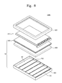
- FIG. 8 is an exploded perspective view showing a liquid crystal display to which a light guide plate fixing structure is applied according to an exemplary embodiment of the present invention.
- a backlight assembly 10 of a liquid crystal display 1000 employs the fixing member 600 shown in FIGS. 3A and 3B .
- the fixing member 600 is arranged in the same manner as the fixing member shown in FIG. 4A .
- all the above-described backlight assemblies may be applied to the liquid crystal display 1000.
- the light source cover of each light emitting unit may be mechanically coupled with the light facing portion of the adjacent light emitting unit, and the mechanical coupling of the light source cover and the light facing portion may be achieved by the fixing member or the protruding fixing member.
- the light guide plate may be supported and fixed by the light guide plate supporting member disposed in the lower space.
- the member to support and fix the light guide plate may be positioned outside the effective light emitting area of the backlight assembly.
- the member to support and fix the light guide plate may be positioned inside the effective light emitting area of the backlight assembly.
- the position and number of the members may be varied if the brightness uniformity of the backlight assembly is obtained and the movement of the light guide plate is prevented.
- the effective light emitting area of the backlight assembly corresponds to a display area, on which images are displayed, of a liquid crystal panel 910.
- the liquid crystal display 1000 according to FIG. 8 includes the backlight assembly 10, the liquid crystal panel 910 disposed on the backlight assembly 10 that selectively transmits the light to display the images, and an upper container 920 that fixes the liquid crystal panel 910 and the backlight assembly 10 to the lower container 100.
- the liquid crystal display according to the present invention employs the hybrid-type backlight assembly, so that the liquid crystal display may be provided in a light weight configuration and may perform local dimming. As a result, the display quality of the liquid crystal display may be improved and the power consumption of the liquid crystal display may be reduced.
Applications Claiming Priority (1)
| Application Number | Priority Date | Filing Date | Title |
|---|---|---|---|
| KR1020100005289A KR101684478B1 (ko) | 2010-01-20 | 2010-01-20 | 복수의 도광판을 갖는 백라이트 어셈블리 |
Publications (1)
| Publication Number | Publication Date |
|---|---|
| EP2348340A1 true EP2348340A1 (fr) | 2011-07-27 |
Family
ID=43479265
Family Applications (1)
| Application Number | Title | Priority Date | Filing Date |
|---|---|---|---|
| EP10014000A Withdrawn EP2348340A1 (fr) | 2010-01-20 | 2010-10-27 | Ensemble de rétroéclairage disposant de plusieurs plaques de guide lumineux |
Country Status (5)
| Country | Link |
|---|---|
| US (1) | US8556491B2 (fr) |
| EP (1) | EP2348340A1 (fr) |
| JP (1) | JP5575626B2 (fr) |
| KR (1) | KR101684478B1 (fr) |
| CN (1) | CN102147079B (fr) |
Families Citing this family (42)
| Publication number | Priority date | Publication date | Assignee | Title |
|---|---|---|---|---|
| US20140041205A1 (en) | 2010-11-19 | 2014-02-13 | Reald Inc. | Method of manufacturing directional backlight apparatus and directional structured optical film |
| TW201310128A (zh) * | 2011-08-24 | 2013-03-01 | Tpv Display Technology Xiamen | 背光模組 |
| KR101236909B1 (ko) * | 2011-09-08 | 2013-02-25 | 명범영 | 복수 개의 도광판 패널 셀들을 이어붙여 대형으로 구성한 도광판 기반 백라이트 장치 |
| CN104380185B (zh) | 2012-05-18 | 2017-07-28 | 瑞尔D斯帕克有限责任公司 | 定向背光源 |
| US9235057B2 (en) | 2012-05-18 | 2016-01-12 | Reald Inc. | Polarization recovery in a directional display device |
| US9350980B2 (en) | 2012-05-18 | 2016-05-24 | Reald Inc. | Crosstalk suppression in a directional backlight |
| US9188731B2 (en) | 2012-05-18 | 2015-11-17 | Reald Inc. | Directional backlight |
| US9678267B2 (en) | 2012-05-18 | 2017-06-13 | Reald Spark, Llc | Wide angle imaging directional backlights |
| EP2850481B1 (fr) | 2012-05-18 | 2018-01-03 | RealD Spark, LLC | Système de commande pour source de lumière directionnelle |
| EP4235270A3 (fr) | 2012-05-18 | 2023-11-08 | RealD Spark, LLC | Agencement de guide d'onde éclairé de façon directionnelle |
| US10062357B2 (en) | 2012-05-18 | 2018-08-28 | Reald Spark, Llc | Controlling light sources of a directional backlight |
| CN104854864B (zh) | 2012-10-02 | 2017-11-17 | 瑞尔D斯帕克有限责任公司 | 具有横向操作模式和纵向操作模式的时间多路复用显示器 |
| US8976081B2 (en) * | 2012-10-17 | 2015-03-10 | Intel Corporation | Integration of displays |
| CN105008983B (zh) | 2012-12-21 | 2018-08-07 | 瑞尔D斯帕克有限责任公司 | 用于定向显示器的超透镜组件 |
| KR20200123175A (ko) | 2013-02-22 | 2020-10-28 | 리얼디 스파크, 엘엘씨 | 지향성 백라이트 |
| JP2016529764A (ja) | 2013-06-17 | 2016-09-23 | リアルディー インコーポレイテッド | 指向性バックライトの光源の制御 |
| WO2015057588A1 (fr) | 2013-10-14 | 2015-04-23 | Reald Inc. | Entrée de lumière pour rétroéclairage directionnel |
| EP3058562A4 (fr) | 2013-10-14 | 2017-07-26 | RealD Spark, LLC | Commande d'affichage directionnel |
| EP3069074A4 (fr) | 2013-11-15 | 2017-08-02 | RealD Spark, LLC | Rétroéclairages directionnels avec des boîtiers d'éléments émetteurs de lumière |
| EP3161550A4 (fr) | 2014-06-26 | 2018-04-18 | RealD Spark, LLC | Dispositif d'affichage intime directionnel |
| CN107003563B (zh) | 2014-10-08 | 2021-01-12 | 瑞尔D斯帕克有限责任公司 | 定向背光源 |
| WO2016105541A1 (fr) | 2014-12-24 | 2016-06-30 | Reald Inc. | Réglage de la rotondité perçue dans une image stéréoscopique d'une tête |
| RU2596062C1 (ru) | 2015-03-20 | 2016-08-27 | Автономная Некоммерческая Образовательная Организация Высшего Профессионального Образования "Сколковский Институт Науки И Технологий" | Способ коррекции изображения глаз с использованием машинного обучения и способ машинного обучения |
| EP3283911B1 (fr) | 2015-04-13 | 2021-12-08 | RealD Spark, LLC | Rétroéclairages directionnels d'imagerie à grand angle |
| CN104834049A (zh) * | 2015-05-15 | 2015-08-12 | 深圳市华星光电技术有限公司 | 背光模组及液晶显示装置 |
| WO2016191598A1 (fr) | 2015-05-27 | 2016-12-01 | Reald Inc. | Rétroéclairages directionnels d'imagerie à grand angle |
| WO2017074951A1 (fr) | 2015-10-26 | 2017-05-04 | Reald Inc. | Système de confidentialité intelligent, appareil et procédé associés |
| US10459321B2 (en) | 2015-11-10 | 2019-10-29 | Reald Inc. | Distortion matching polarization conversion systems and methods thereof |
| EP4293417A3 (fr) | 2015-11-13 | 2024-01-24 | RealD Spark, LLC | Éléments de surface pour rétroéclairages directionnels d'imagerie |
| CN108463667B (zh) | 2015-11-13 | 2020-12-01 | 瑞尔D斯帕克有限责任公司 | 广角成像定向背光源 |
| EP3400706B1 (fr) | 2016-01-05 | 2022-04-13 | RealD Spark, LLC | Correction du regard d'images multi-vues |
| US11079619B2 (en) | 2016-05-19 | 2021-08-03 | Reald Spark, Llc | Wide angle imaging directional backlights |
| WO2017205183A1 (fr) | 2016-05-23 | 2017-11-30 | Reald Spark, Llc | Rétroéclairages directionnels d'imagerie à grand angle |
| CN106647028A (zh) * | 2016-12-23 | 2017-05-10 | 深圳市华星光电技术有限公司 | 背光模组及液晶显示器 |
| EP3566094B1 (fr) | 2017-01-04 | 2023-12-06 | RealD Spark, LLC | Empilement optique pour imagerie de rétroéclairages directionnels |
| CN106873240B (zh) * | 2017-02-07 | 2020-05-19 | 深圳市华星光电技术有限公司 | 背光组件及液晶显示模组 |
| WO2018187154A1 (fr) | 2017-04-03 | 2018-10-11 | Reald Spark, Llc | Rétroéclairages directionnels d'imagerie segmentée |
| WO2019032604A1 (fr) | 2017-08-08 | 2019-02-14 | Reald Spark, Llc | Ajustement d'une représentation numérique d'une région de tête |
| US11109014B2 (en) | 2017-11-06 | 2021-08-31 | Reald Spark, Llc | Privacy display apparatus |
| US10802356B2 (en) | 2018-01-25 | 2020-10-13 | Reald Spark, Llc | Touch screen for privacy display |
| US11821602B2 (en) | 2020-09-16 | 2023-11-21 | Reald Spark, Llc | Vehicle external illumination device |
| WO2024030274A1 (fr) | 2022-08-02 | 2024-02-08 | Reald Spark, Llc | Affichage proche de l'œil de suivi de pupille |
Citations (3)
| Publication number | Priority date | Publication date | Assignee | Title |
|---|---|---|---|---|
| US20060221638A1 (en) * | 2005-04-01 | 2006-10-05 | Chew Tong F | Light-emitting apparatus having a plurality of adjacent, overlapping light-guide plates |
| WO2009145548A2 (fr) * | 2008-05-27 | 2009-12-03 | Lg Electronics Inc. | Unité de rétroéclairage à del et dispositif d’affichage à cristaux liquides utilisant l’unité |
| WO2009157351A1 (fr) * | 2008-06-23 | 2009-12-30 | ソニー株式会社 | Dispositif à source de lumière plane et dispositif d’affichage |
Family Cites Families (9)
| Publication number | Priority date | Publication date | Assignee | Title |
|---|---|---|---|---|
| JP3373427B2 (ja) * | 1998-03-31 | 2003-02-04 | 日東樹脂工業株式会社 | タンデム型面光源装置 |
| KR100654220B1 (ko) * | 1999-08-03 | 2006-12-05 | 삼성전자주식회사 | 액정표시장치 |
| JP2001312916A (ja) * | 2000-02-24 | 2001-11-09 | Sony Corp | 面光源装置 |
| KR100914392B1 (ko) * | 2002-12-31 | 2009-08-28 | 엘지디스플레이 주식회사 | 백라이트 어셈블리 |
| JP2006108033A (ja) * | 2004-10-08 | 2006-04-20 | Mitsubishi Rayon Co Ltd | タンデム型面光源装置 |
| JP2006134748A (ja) * | 2004-11-08 | 2006-05-25 | Mitsubishi Rayon Co Ltd | タンデム型面光源装置 |
| CN101490470B (zh) * | 2006-10-27 | 2011-06-22 | 夏普株式会社 | 光源装置、背光源装置和液晶显示装置 |
| CN201247363Y (zh) * | 2008-08-22 | 2009-05-27 | 北京京东方光电科技有限公司 | 背光模组 |
| US8223296B2 (en) * | 2008-08-25 | 2012-07-17 | Lg Display Co. Ltd. | Backlight unit and liquid crystal display device having the same |
-
2010
- 2010-01-20 KR KR1020100005289A patent/KR101684478B1/ko active IP Right Grant
- 2010-09-28 US US12/892,545 patent/US8556491B2/en not_active Expired - Fee Related
- 2010-10-27 EP EP10014000A patent/EP2348340A1/fr not_active Withdrawn
- 2010-12-07 JP JP2010272957A patent/JP5575626B2/ja not_active Expired - Fee Related
-
2011
- 2011-01-07 CN CN201110002692.XA patent/CN102147079B/zh not_active Expired - Fee Related
Patent Citations (3)
| Publication number | Priority date | Publication date | Assignee | Title |
|---|---|---|---|---|
| US20060221638A1 (en) * | 2005-04-01 | 2006-10-05 | Chew Tong F | Light-emitting apparatus having a plurality of adjacent, overlapping light-guide plates |
| WO2009145548A2 (fr) * | 2008-05-27 | 2009-12-03 | Lg Electronics Inc. | Unité de rétroéclairage à del et dispositif d’affichage à cristaux liquides utilisant l’unité |
| WO2009157351A1 (fr) * | 2008-06-23 | 2009-12-30 | ソニー株式会社 | Dispositif à source de lumière plane et dispositif d’affichage |
Also Published As
| Publication number | Publication date |
|---|---|
| KR20110085476A (ko) | 2011-07-27 |
| CN102147079A (zh) | 2011-08-10 |
| US8556491B2 (en) | 2013-10-15 |
| US20110176292A1 (en) | 2011-07-21 |
| CN102147079B (zh) | 2015-07-08 |
| JP2011151005A (ja) | 2011-08-04 |
| JP5575626B2 (ja) | 2014-08-20 |
| KR101684478B1 (ko) | 2016-12-09 |
Similar Documents
| Publication | Publication Date | Title |
|---|---|---|
| US8556491B2 (en) | Backlight assembly having a plurality of light guide plates | |
| US8757844B2 (en) | Backlight unit and display device including the same | |
| US8801209B2 (en) | Backlight assembly and display device having lower profile and/or reduced weight | |
| US8553171B2 (en) | Display device | |
| TWI499839B (zh) | 背光總成 | |
| US8704974B2 (en) | Backlight assembly comprising a light-sourcing unit fixing frame with a lateral extension portion and a fixing protrusion which interlocks the light-sourcing unit fixing frame to a housing | |
| US8740445B2 (en) | Backlight assembly and method of assembling a backlight assembly | |
| US8734001B2 (en) | Backlight assembly including a light source cover including a sidewall cover portion which contacts with an exterior surface of a sidewall of a receiving container and a light source cover portion which covers a light source and a portion of the exiting surface of a light guide plate, display device having the same and method of assembling the display device | |
| EP2437105A1 (fr) | Affichage à cristaux liquides | |
| US20080239754A1 (en) | Backlight assembly, display apparatus having the same and method for manufacturing the same | |
| EP2390694B1 (fr) | Unité de rétroéclairage et dispositif d'affichage | |
| US8636374B2 (en) | Backlight unit and display device including the same | |
| KR101308873B1 (ko) | 액정표시장치 | |
| KR20180014299A (ko) | 도광판 홀더 및 이를 구비하는 면 광원 장치 | |
| KR20120090301A (ko) | 백라이트 어셈블리 및 이를 갖는 표시장치 | |
| KR101814816B1 (ko) | 조명 유닛 및 이를 포함하는 액정표시장치 | |
| US20120236592A1 (en) | Display apparatus including light guide plate coupling member | |
| KR20110094597A (ko) | 슬라이드 방식의 led 패키지 장착 구조를 갖는 백 라이트 유닛 | |
| JP4377754B2 (ja) | 面光源装置及び液晶表示装置 | |
| KR20160053440A (ko) | 커버버텀 엠보 형상을 이용한 백라이트 장치의 광학 갭 유지 구조 | |
| KR20200099225A (ko) | 표시 장치 | |
| KR20180138233A (ko) | 백라이트 장치 | |
| KR20110127554A (ko) | 액정표시장치 |
Legal Events
| Date | Code | Title | Description |
|---|---|---|---|
| PUAI | Public reference made under article 153(3) epc to a published international application that has entered the european phase |
Free format text: ORIGINAL CODE: 0009012 |
|
| AK | Designated contracting states |
Kind code of ref document: A1 Designated state(s): AL AT BE BG CH CY CZ DE DK EE ES FI FR GB GR HR HU IE IS IT LI LT LU LV MC MK MT NL NO PL PT RO RS SE SI SK SM TR |
|
| AX | Request for extension of the european patent |
Extension state: BA ME |
|
| 17P | Request for examination filed |
Effective date: 20120104 |
|
| RAP1 | Party data changed (applicant data changed or rights of an application transferred) |
Owner name: SAMSUNG ELECTRONICS CO., LTD. |
|
| RAP1 | Party data changed (applicant data changed or rights of an application transferred) |
Owner name: SAMSUNG DISPLAY CO., LTD. |
|
| RAP1 | Party data changed (applicant data changed or rights of an application transferred) |
Owner name: SAMSUNG DISPLAY CO., LTD. |
|
| STAA | Information on the status of an ep patent application or granted ep patent |
Free format text: STATUS: THE APPLICATION HAS BEEN WITHDRAWN |
|
| 18W | Application withdrawn |
Effective date: 20170907 |