EP2347426B2 - Schaltanordnung und damit ausgestattete schaltanlage - Google Patents
Schaltanordnung und damit ausgestattete schaltanlage Download PDFInfo
- Publication number
- EP2347426B2 EP2347426B2 EP09736957.3A EP09736957A EP2347426B2 EP 2347426 B2 EP2347426 B2 EP 2347426B2 EP 09736957 A EP09736957 A EP 09736957A EP 2347426 B2 EP2347426 B2 EP 2347426B2
- Authority
- EP
- European Patent Office
- Prior art keywords
- knife
- bus bar
- projection
- switch device
- switch
- Prior art date
- Legal status (The legal status is an assumption and is not a legal conclusion. Google has not performed a legal analysis and makes no representation as to the accuracy of the status listed.)
- Active
Links
Images

Classifications
-
- H—ELECTRICITY
- H01—ELECTRIC ELEMENTS
- H01H—ELECTRIC SWITCHES; RELAYS; SELECTORS; EMERGENCY PROTECTIVE DEVICES
- H01H1/00—Contacts
- H01H1/12—Contacts characterised by the manner in which co-operating contacts engage
- H01H1/36—Contacts characterised by the manner in which co-operating contacts engage by sliding
- H01H1/42—Knife-and-clip contacts
-
- H—ELECTRICITY
- H01—ELECTRIC ELEMENTS
- H01H—ELECTRIC SWITCHES; RELAYS; SELECTORS; EMERGENCY PROTECTIVE DEVICES
- H01H1/00—Contacts
- H01H1/02—Contacts characterised by the material thereof
- H01H1/021—Composite material
- H01H1/023—Composite material having a noble metal as the basic material
-
- H—ELECTRICITY
- H01—ELECTRIC ELEMENTS
- H01H—ELECTRIC SWITCHES; RELAYS; SELECTORS; EMERGENCY PROTECTIVE DEVICES
- H01H1/00—Contacts
- H01H1/02—Contacts characterised by the material thereof
- H01H1/021—Composite material
- H01H1/025—Composite material having copper as the basic material
Definitions
- the present invention relates to a switch device comprising a bus bar and a switch knife, wherein the knife is arranged so as to pivot around an axis perpendicular to a longitudinal axis of the bus bar.
- the invention also relates to medium or high voltage switchgear provided with a switch device in accordance with the invention.
- a bus bar is referred to as a voltage-carrying electric conductor.
- the switch device may be provided for the purpose of connecting or disconnecting the bus bar from/to any further electric power distribution components, such as a cable.
- a plurality of switches may be provided in order to connect a plurality of elements, such as electric cables, to a predetermined bus bar.
- Contemporary selector switches of medium voltage switchgear are used for disconnecting a part of an interrupter from a bus bar upon activation of the interrupter.
- the selector switch comprises a connector element called a knife that, after interruption by means of an in series connected interrupter or breaker has taken place, moves from a first position, in which it is in electric contact with the bus bar, to a second position, in which it is electrically disconnected from the bus bar. In the second position, the switch knife may be electrically connected to ground.
- the selector switch may be provided in a switchgear housing filled with any suitable electrically insulating gas or gas mixture, such as SF6.
- the bus bar may have a rectangular cross-section and be made of copper, possibly covered by a layer of silver.
- a connector element formed by a hooked copper plate is attached to the bus bar at a location corresponding to the location of the switch knife.
- the connector element comprises a first shank attached to the bus bar, and a second shank extending perpendicularly to the first shank and forming an element to be contacted by the switch knife.
- the first shank of the connector element may be bolted to the bus bar.
- the knife normally comprises two parallel shanks or arms that, in the first position in which the knife contacts the second shank of the connector element, overlap said second shank on opposite sides thereof.
- those surfaces of the knife that are assumed to contact the second shank of the connector element are provided with projections, preferably bulges, in order to guarantee a good and reliable contact.
- Document EP 0 310 211 discloses a device according to the preamble of claim 1.
- the object of the invention is achieved by providing a switch device comprising the features of claim 1.
- the switch knife operates directly against the bus bar, without any intermediate connector element.
- the projection of the bus bar will form a connector element that, in contrast to connector elements of prior art, is an integrated part of the bus bar.
- the switch device of the present invention promotes a cost efficient production thereof, and has a robust design with few components in relation to prior art.
- the projection extends in the longitudinal direction of the bus bar, advantageously along the whole length of the bus bar.
- the projection forms a portion that protrudes from the rest of the bus bar, in a direction towards the switch knife, and has a smaller thickness, or width, than the rest of the bus bar.
- the bus bar may have a T-shape as seen in a cross-section thereof.
- the cross section of said projection remains the same along the longitudinal direction of the bus bar.
- the projection is integral with the bus bar. This embodiment further promotes a cost efficient production of a switch device, and provides a robust switch device design with few components in relation to prior art.
- a lateral elevation extending in the longitudinal direction of the bus bar, said knife being arranged to contact said elevation when pivoted into its first position.
- the elevation is lateral in relation to the longitudinal direction of the bus bar, or alternatively, the elevation has an extension in a lateral, or transverse, direction in relation to the longitudinal direction of the bus bar.
- the elevation extends in the longitudinal direction of the projection.
- the elevation forms a lateral rib or bulge on said projection.
- the elevation is provided on a side of the projection of the bus bar on which at least a part of the knife is arranged to contact the bus bar. Accordingly, said part of the knife will should be arranged so as to be applied with a lateral force against said elevation or bulge when moved into its first position, i.e. the position in which it is in direct contact with the bus bar.
- the knife is provided with a spring element that provides a spring force that, in said first position, forces the knife into contact with the lateral elevation of the bus bar.
- a lateral elevation extending in the longitudinal direction of the bus bar, said knife being arranged to contact each such elevation when pivoted into its first position.
- Each elevation is lateral in relation to the longitudinal direction of the bus bar, or alternatively, each elevation has an extension in a lateral, or transverse, direction in relation to the longitudinal direction of the bus bar.
- both elevations are arranged in correspondence with the above description for the at least one elevation.
- the knife comprises two parallel shanks separated by a gap. The shanks are flexibly arranged, thereby permitting a delimited altering of the gap between them.
- a spring element is provided in said gap in engagement with the respective shank, whereby, in said first position, the spring element urges the shanks towards each other, thereby promoting a clamping of the bus bar between the shanks of the switch knife.
- the projection in a region in which the projection is in contact with the knife when the latter is in its first position, presents an outer surface comprising a material of less prone to oxidation than the bulk part of the switch knife.
- said outer surface has a higher mechanical strength, in particular a higher wear resistivity than the material of the bulk part of the bus bar.
- said outer surface has Sn, Ni, Ag or Au as its main constituent.
- a bulk part of the bus bar may comprise a material that is optimized for its function as a conductor and may promote a cost efficient production of the bus bar, while said surface is optimized to the specific requirements of such a surface, such as being more subjected to corrosion than the rest of the bus bar.
- the projection in a region adjacent to the region in which said outer surface is provided, the projection is covered by a material to which the main constituent of said outer surface is non-adhesive.
- the bus bar has been provided with a cover or mask onto which a layer comprising any of Sn, Ni, Ag or Au is unlikely to adhere, wherein said mask does not cover those areas in which a layer of Sn, Ni, Ag or Au is to be provided.
- the cover layer or mask comprises an electrically insulating material, in order to further prevent corrosion of the bus bar.
- it covers all the surface of the bus bar that is not covered by said outer surface comprising Ni, Sn, Ag or Au.
- a bulk part of the bus bar comprises aluminium as its main constituent.
- Aluminium is an advantageous material from both an environmental point of view and from a purely cost-related point of view. It is easily extruded, which is of importance in this context since, according to the switch device according to the present invention, the bus bar is formed by an extruded profile.
- the extruded profile comprises the above-mentioned projection as well as advantageously lateral elevations provided on the latter.
- a bus bar made of aluminium may or may not be provided with the above-mentioned outer surface of different material.
- said knife comprises two shanks separated by a gap, said shanks being arranged so as to contact opposite sides of said projection of the bus bar when the knife is in its first position.
- a bulk part of the knife comprises Cu as a main constituent.
- Cu is advantageous with regard to its low electric resistivity.
- aluminium may be used as a main constituent of the bulk part of the switch knife.
- the switch device in a region in which the knife is in contact with the projection when in its first position, the knife presents an outer surface comprising Sn, Ni, Ag or Au as its main constituent.
- an improved corrosion resistance of the knife is provided in those contact areas in which the corrosion conditions are harsher.
- the switch device comprises a stop means for preventing pivoting of the knife from the second position beyond the first position. Any such pivoting of the knife beyond the first position would result in a situation in which the risk of having electric discharges between the knife and the bus bar would be obvious. Since such discharges might be detrimental for the functionality of a switchgear or the like in which the switch may be provided, this feature confers an advantage to the device.
- the stop means may be provided on the bus bar or on the switch knife, or on a shaft by means of which the switch knife is rotated between its different positions.
- such a means may include a stop heel or the like, preventing excessive rotation of such a shaft from the second position beyond the first position.
- the device comprises a securing means for securing the knife in its first position. Thereby, accidental disconnection of the knife from the bus bar is further avoided.
- said securing means comprises a recess provided in said projection of the bus bar.
- the knife may then present an engagement element for engagement with said recess.
- said engagement element comprises a pin or bolt that engages each of two opposite shanks of the switch knife and extends in a lateral direction through the gap between said shanks.
- the device may comprise a rack and pinion gear provided so as to urge the engagement means of the switch knife, i.e. said pin or bolt, into engagement with the engagement means of the bus bar, i.e. said recess, in said first position and lock the switch knife in said position.
- the knife is displaceable in relation to and perpendicularly to its pivotation axis through a translational motion in order to permit the securing of the knife in relation to the bus bar.
- Solutions with a spring acting either on the pin, if the latter is displaceably arranged in relation to the rest of the knife, or on the knife, if the latter is displaceably arranged in relation to its pivotation axis, are also conceived.
- the device may comprise a spring provided so as to urge said pin or bolt into engagement with said recess in said first position and lock the latter in said position.
- the pin may be displaceable in relation to the knife, or the knife may be displaceable in relation and perpendicularly to its pivotation axis through a translational motion in order to permit the securing of the knife in relation to the bus bar.
- Said spring may act either on the pin, if the latter is displaceably arranged in relation to the rest of the knife, or on the knife, if the latter is displaceably arranged in relation to its pivotation axis.
- the invention also relates to a medium or high voltage switchgear, which is characterized in that it comprises a switch device according to the invention.
- a switchgear comprises at least one, but advantageously a plurality of compartments, each carrying three bushings (one for each phase in a three-phase system) to be connected to three exterior power cables outside the switchgear, a breaker for each phase inside said compartment, an electric conductor that extends from the bushing of each phase to a first end of a breaker, and a switch knife (one for each phase, used for connecting or disconnecting a second end of said breaker to/from an electric connector formed by a so-called bus-bar (one for each phase) that extends through the compartments.
- the switchgear advantageously defines an inner space in which said switch device is arranged. It might be advantageous said inner space being filled with an electrically insulating gas mixture.
- the gas mixture may contain oxygen, whereby the provision of oxidation resistant or corrosion resistant surfaces on the switch knife and the bus bar will be advantageous.
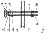
- Fig. 1 shows an electric power distribution switchgear 1 according to the invention.
- the switchgear 1 comprises an encapsulation 2, advantageously made of or at least comprising a metal, inside which a number of switch devices 3, only one of which is shown in the figure, are housed.
- the switch devices not shown in the figure are arranged in parallel with the one shown and are thus either hidden behind the one shown or located in planes in front of the latter and not shown in the figure.
- a wall of the encapsulation 2 is penetrated by a number of bushings 4, one for each phase of a plural phase system. From each bushing 4 a respective conductor 5, only one of which is shown in the figure, extends to a respective switch device 3.
- the bushings 4 are connected to cables, not shown, that either connect the switchgear 1 to a load or to a medium or high voltage power distribution line.
- Each switch device 3 comprises a breaker 6 connected in one end to the conductor 5 that extends from a dedicated bushing 4, and in another end to a switch 7.
- the breaker 6 is a vacuum interrupter that, though not shown in the drawing but as known per se, has a fixed part and a moveable part, wherein the fixed part is connected the conductor 5 and the moveable part is connected to the switch.
- the switch 7 is a so called safety switch or selector switch which is not adapted to break a medium or high voltage circuit itself but only to disconnect the breaker from a medium or high voltage line after breaking has been performed by means of the breaker.
- the switch 7 comprises a contact element 8 permanently connected to the breaker 6, and a switch knife 9.
- the switch knife is movable between positions in which it connects the breaker 6 with a further conductor 10 formed by a so called bus bar that extends through the switchgear 1, with ground or an open position in which the breaker is neither connected to the bus bar nor to the ground.
- a switchgear may comprise a plurality of switchgears, or units, such as the one described above.
- the encapsulation may or may not be common for the plurality of switchgear/units.
- the encapsulation may be filled with an electrically insulating gas or gas mixture, which, advantageously, is pressurised. Air-filled encapsulations are also conceived.
- the switch device 3 comprises a shaft 11 onto which the switch knife 9 is attached.
- the shaft 11 is common for the parallel three switches 7 of the three-phase switchgear described so far.
- the shaft 11 extends through a wall of the encapsulation 2 and is manoeuvrable from outside the encapsulation 2.
- the bus bar 10 extends horizontally in an upper part of the compartment defined by the encapsulation 2, and there is provided a grounded element 12 on an inner wall of the encapsulation 2, below the level of the bus bar 10.
- the bus bar 10 is formed by an extruded metal profile based on aluminium.
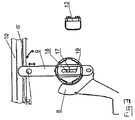
- Fig. 2 shows the cross-section of said profile.
- Said profile comprises a base part 13, i.e. the upper part as shown in fig. 2 , from which a projection 14 of smaller width than the base part extends towards the region of the switch knife 9, i.e. downwards in the embodiment presented here.
- the projection 14 is integral with the bus bar 10.
- the switch knife 9 in a first position in which it physically and electrically connected to the bus bar 10.
- the knife 9 comprises two opposite shanks 9a, 9b held by the shaft 11. An end of each shank of the knife overlaps the projection 14 in the connected position and a spring 16 provided between the shanks provides for pretension of the knife shanks against the bulges 15 of the bus bar 10.
- a second shaft 17 coaxially with and inside the first shaft 11. The function of the second shaft 17 will be explained later.
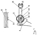
- Fig. 3 corresponds to fig. 2 , but shows the switch from a perpendicular angle.
- the second shaft 17 carries teeth 18, suitably on a geared wheel attached to the shaft 17.
- the knife 9 comprises an elongated slot that extends in the longitudinal direction thereof. Along a side of the slot there is provided a rack 19, such that, upon rotation of the shaft 17 a longitudinal displacement of the knife 9 in relation to the first shaft 11 and to its privation axis is achieved.
- the knife 9 is slideably seated in or attached to the shaft 11 in order to allow such displacement.
- the switch comprises a rack and pinion gear by means of which longitudinal displacement of the switch knife 9 is permitted.
- the second shaft 17, likewise the first shaft 11, should extend such that it is manoeuvrable from outside the encapsulation 2.
- an engagement means formed by a pin or tap 20 that extends between the shanks 9a, 9b of the switch knife in the region of the end in which the knife 9 contacts the bus bar 10.
- a corresponding engagement means formed by a recess 21 provided in the bus bar 10.
- the projection 14 presents an outer surface comprising Sn, Ni, Ag or Au as its main constituent.
- the bulk part of the bus bar advantageously comprises an Aluminum alloy.
- the projection 14 is covered by a material to which the main constituent of said outer surface is not adhesive.
- the bus bar 10 has been provided with a cover or mask onto which a layer comprising any of Sn, Ni, Ag or Au is unlikely to adhere, wherein said mask does not cover those areas in which a layer of Sn, Ni, Ag or Au is to be provided.
- the cover layer or mask comprises an electrically insulating material, in order to further prevent corrosion of the bus bar.
- it covers all the surface of the bus bar that is not covered by said outer surface comprising Ni, Sn, Ag or Au.
- a bulk part of the knife 9 comprises Cu as a main constituent.
- Cu is advantageous with regard to its low electric resistivity.
- the knife 9 presents an outer surface comprising Sn, Ni, Ag or Au as its main constituent. Thereby, an improved corrosion resistance of the knife 9 is provided in those contact areas in which the corrosion conditions may be harsher.
- bus bar 10 may comprise more than one projection provided to contact the switch knife in the connected first position.
- switch knife 9 may be comprised by only one piece instead of the double shanks 9a, 9b presented here.
Landscapes
- Arc-Extinguishing Devices That Are Switches (AREA)
- Rotary Switch, Piano Key Switch, And Lever Switch (AREA)
Claims (13)
- Schaltanordnung, umfassend- eine Sammelschiene (10), und- ein Schaltermesser (9),- wobei das Messer (9) so angeordnet ist, dass es um eine Achse senkrecht zu einer Längsachse der Sammelschiene (10) schwenkbar ist, wobei- die Sammelschiene (10) einen hervorstehenden Abschnitt (14) aufweist, und wobei das Messer (9) schwenkbar ist zu einer ersten Position, in welcher es in direktem Kontakt mit dem hervorstehenden Abschnitt (14) ist und zu einer zweiten Position, in der es dem Kontakt mit dem hervorstehenden Abschnitt (14) entzogen ist,dadurch gekennzeichnet, dass der hervorstehende Abschnitt ein integrierter Teil der Sammelschiene (10) ist, wobei ein Bulk-Teil der Sammelschiene (10) Aluminium als Hauptbestandteil umfasst und die Sammelschiene (10) durch ein Strangpressprofil gebildet wird, wobei das Strangpressprofil den hervorstehenden Abschnitt umfasst.
- Schaltanordnung gemäß Anspruch 1, dadurch gekennzeichnet, dass auf mindestens einer Seite des hervorstehenden Abschnitts (14) eine seitliche Erhebung (15) bereitgestellt ist, die sich in Längsrichtung der Sammelschiene (10) ausdehnt, wobei das Messer (9) so angeordnet ist, dass es in Kontakt mit der Erhebung (15) beim Schwenken in seine erste Position tritt.
- Schaltanordnung nach einem der Ansprüche 1 bis 2, dadurch gekennzeichnet, dass auf gegenüberliegenden Seiten des hervorstehenden Abschnitts (14) eine seitliche Erhebung (15) bereitgestellt ist, die sich in Längsrichtung der Sammelschiene (10) ausdehnt, wobei das Messer (9) so angeordnet ist, dass es in Kontakt mit der Erhebung (15) beim Schwenken in seine erste Position tritt.
- Schaltanordnung nach einem der Ansprüche 1-3, dadurch gekennzeichnet, dass in einem Bereich, in dem der hervorstehende Abschnitt (14) in Kontakt mit dem Messer (9) ist, wenn sich dieses in seiner ersten Position befindet, der hervorstehende Abschnitt (14) eine Außenfläche umfassend Sn, Ni, Ag oder Au als Hauptbestandteil aufweist.
- Schaltanordnung nach Anspruch 4, dadurch gekennzeichnet, dass in einem Bereich, angrenzend an den Bereich, in dem die Außenfläche bereitgestellt ist, der hervorstehende Abschnitt (14) von einem Material bedeckt ist, an welches der Hauptbestandteil der Außenfläche nicht haftet.
- Schaltanordnung nach einem der Ansprüche 1-5, dadurch gekennzeichnet, dass das Messer (9) zwei durch einen Spalt getrennte Schäfte (9a, 9b) umfasst, wobei die Schäfte (9a, 9b) so angeordnet sind, dass sie mit den gegenüberliegenden Seiten des hervorstehenden Abschnitts (14) der Sammelschiene (10) in Kontakt sind, wenn sich das Messer (9) in seiner ersten Position befindet.
- Schaltanordnung nach einem der Ansprüche 1-6, dadurch gekennzeichnet, dass ein Bulk-Teil des Messers (9) Cu als Hauptbestandteil umfasst.
- Schaltanordnung nach einem der Ansprüche 1-7, dadurch gekennzeichnet, dass in einem Bereich, in dem das Messer (9) in Kontakt mit dem hervorstehenden Abschnitt (14) ist, wenn es sich in seiner ersten Position befindet, das Messer (9) eine Außenfläche umfassend Sn, Ni, Ag oder Au als Hauptbestandteil aufweist.
- Schaltanordnung nach einem der Ansprüche 1-8, dadurch gekennzeichnet, dass sie ein Stoppmittel zur Verhinderung des Schwenkens des Messers (9) von der zweiten Position über die erste Position hinaus umfasst.
- Schaltanordnung nach einem der Ansprüche 1-9, dadurch gekennzeichnet, dass sie ein Sicherungsmittel (17, 18, 19, 20, 21) zum Sichern des Messers (9) in seiner ersten Position umfasst.
- Schaltanordnung gemäß Anspruch 10, dadurch gekennzeichnet, dass das Sicherungsmittel eine in dem hervorstehenden Abschnitt (14) der Sammelschiene (10) bereitgestellte Aussparung (21) aufweist.
- Mittel- oder Hochspannungsschaltanlage, dadurch gekennzeichnet, dass sie eine Schaltanordnung nach einem der Ansprüche 1-11 umfasst.
- Schaltanlage nach Anspruch 12, dadurch gekennzeichnet, dass sie einen Innenraum definiert, in dem die Schaltanordnung angeordnet ist, wobei der Innenraum mit einem sauerstoffhaltigen Gasgemisch gefüllt ist.
Priority Applications (1)
| Application Number | Priority Date | Filing Date | Title |
|---|---|---|---|
| EP09736957.3A EP2347426B2 (de) | 2008-10-27 | 2009-10-19 | Schaltanordnung und damit ausgestattete schaltanlage |
Applications Claiming Priority (3)
| Application Number | Priority Date | Filing Date | Title |
|---|---|---|---|
| EP08167603A EP2180486A1 (de) | 2008-10-27 | 2008-10-27 | Schaltvorrichtung und damit ausgerüstete Schaltanlage |
| PCT/EP2009/063664 WO2010049307A1 (en) | 2008-10-27 | 2009-10-19 | A switch device and a switchgear provided therewith |
| EP09736957.3A EP2347426B2 (de) | 2008-10-27 | 2009-10-19 | Schaltanordnung und damit ausgestattete schaltanlage |
Publications (3)
| Publication Number | Publication Date |
|---|---|
| EP2347426A1 EP2347426A1 (de) | 2011-07-27 |
| EP2347426B1 EP2347426B1 (de) | 2013-01-02 |
| EP2347426B2 true EP2347426B2 (de) | 2016-09-07 |
Family
ID=40445715
Family Applications (2)
| Application Number | Title | Priority Date | Filing Date |
|---|---|---|---|
| EP08167603A Withdrawn EP2180486A1 (de) | 2008-10-27 | 2008-10-27 | Schaltvorrichtung und damit ausgerüstete Schaltanlage |
| EP09736957.3A Active EP2347426B2 (de) | 2008-10-27 | 2009-10-19 | Schaltanordnung und damit ausgestattete schaltanlage |
Family Applications Before (1)
| Application Number | Title | Priority Date | Filing Date |
|---|---|---|---|
| EP08167603A Withdrawn EP2180486A1 (de) | 2008-10-27 | 2008-10-27 | Schaltvorrichtung und damit ausgerüstete Schaltanlage |
Country Status (4)
| Country | Link |
|---|---|
| US (1) | US8969748B2 (de) |
| EP (2) | EP2180486A1 (de) |
| CN (1) | CN102203892B (de) |
| WO (1) | WO2010049307A1 (de) |
Families Citing this family (9)
| Publication number | Priority date | Publication date | Assignee | Title |
|---|---|---|---|---|
| EP2180568A1 (de) * | 2008-10-27 | 2010-04-28 | ABB Technology AG | Stromverteilungsanordnung und Schaltanlage damit |
| AU2011370756B2 (en) * | 2011-06-16 | 2015-09-24 | Abb Schweiz Ag | A switching device and a switchgear |
| JP2017134885A (ja) * | 2014-06-12 | 2017-08-03 | 三菱電機株式会社 | ガス絶縁スイッチギヤの開閉器およびガス絶縁開閉装置 |
| CN107579498B (zh) * | 2017-10-09 | 2023-06-06 | 南方电网科学研究院有限责任公司 | 一种阀厅金具 |
| US10629391B2 (en) * | 2017-12-21 | 2020-04-21 | Eaton Intelligent Power Limited | Fusible safety disconnect in solid state circuit breakers and combination motor starters |
| CN108364813B (zh) * | 2018-05-02 | 2023-12-15 | 隆鑫通用动力股份有限公司 | 一种开关切换装置及切换系统 |
| CN112136198B (zh) * | 2018-05-10 | 2023-04-28 | 三菱电机株式会社 | 开关 |
| FR3122283A1 (fr) * | 2021-04-26 | 2022-10-28 | Schneider Electric Industries Sas | Système de coupure d’un appareil électrique |
| EP4243046A1 (de) * | 2022-03-10 | 2023-09-13 | Abb Schweiz Ag | Elektrischer strommesserschalter |
Citations (1)
| Publication number | Priority date | Publication date | Assignee | Title |
|---|---|---|---|---|
| DE3735191A1 (de) † | 1987-10-17 | 1989-05-03 | Asea Brown Boveri | Stromschiene |
Family Cites Families (10)
| Publication number | Priority date | Publication date | Assignee | Title |
|---|---|---|---|---|
| US3478185A (en) * | 1967-10-31 | 1969-11-11 | G & W Electric Speciality Co | Switch and contact arrangement |
| US3641300A (en) * | 1969-08-15 | 1972-02-08 | Allis Chalmers Mfg Co | Electrical contact |
| US3739115A (en) * | 1971-06-17 | 1973-06-12 | Esco Mfg Co | Switching apparatus |
| SE364139B (de) * | 1972-06-27 | 1974-02-11 | Asea Ab | |
| US4061896A (en) * | 1974-05-24 | 1977-12-06 | Clancy John F | Modular vault-type load break switch |
| US4025747A (en) * | 1975-09-11 | 1977-05-24 | Westinghouse Electric Corporation | Circuit interrupter stab assembly with self-aligning clip type contact |
| US4467161A (en) * | 1982-11-10 | 1984-08-21 | G & W Electric Company | Switch apparatus |
| US5025121A (en) * | 1988-12-19 | 1991-06-18 | Siemens Energy & Automation, Inc. | Circuit breaker contact assembly |
| US5241144A (en) * | 1992-06-24 | 1993-08-31 | Emerson Electric Co. | Self-adjusting multicircuit brake switch |
| CN201138633Y (zh) * | 2007-12-10 | 2008-10-22 | 河南森源电气股份有限公司 | 一种隔离开关触指和触头接触配合结构 |
-
2008
- 2008-10-27 EP EP08167603A patent/EP2180486A1/de not_active Withdrawn
-
2009
- 2009-10-19 WO PCT/EP2009/063664 patent/WO2010049307A1/en not_active Ceased
- 2009-10-19 CN CN200980142708.8A patent/CN102203892B/zh active Active
- 2009-10-19 EP EP09736957.3A patent/EP2347426B2/de active Active
-
2011
- 2011-04-27 US US13/095,386 patent/US8969748B2/en active Active
Patent Citations (1)
| Publication number | Priority date | Publication date | Assignee | Title |
|---|---|---|---|---|
| DE3735191A1 (de) † | 1987-10-17 | 1989-05-03 | Asea Brown Boveri | Stromschiene |
Also Published As
| Publication number | Publication date |
|---|---|
| US20110226528A1 (en) | 2011-09-22 |
| US8969748B2 (en) | 2015-03-03 |
| EP2180486A1 (de) | 2010-04-28 |
| EP2347426A1 (de) | 2011-07-27 |
| CN102203892B (zh) | 2015-05-20 |
| EP2347426B1 (de) | 2013-01-02 |
| CN102203892A (zh) | 2011-09-28 |
| WO2010049307A1 (en) | 2010-05-06 |
Similar Documents
| Publication | Publication Date | Title |
|---|---|---|
| US8969748B2 (en) | Switch device and a switchgear provided therewith | |
| EP2337052B1 (de) | Schaltvorrichtung und Schaltanlage | |
| KR100997226B1 (ko) | 진공 절연 스위치 기어 | |
| EP2721624B1 (de) | Schaltvorrichtung und schaltanlage | |
| EP2073332B1 (de) | Trennschalter mit drei Positionen für Mittelspannungstafeln | |
| US20140104758A1 (en) | Switching Device And A Switchgear | |
| EP2180490B1 (de) | Schaltungsvorrichtung, Schaltanlage damit und Verfahren zum Betreiben einer Schaltungsvorrichtung | |
| CN101040411B (zh) | 具有去联锁的电弧限制器的开关设备 | |
| EP1965476A1 (de) | Kombinierte Schutzschalter- und Trennschaltermontage in einer fest installierten elektrischen Schaltanlage | |
| US10475609B2 (en) | Disconnecting device for a power line and method for disconnecting a power line | |
| KR101213615B1 (ko) | 회로를 스위칭하기 위한 디바이스 | |
| EP2347488B1 (de) | Elektrische stromverteilungsanordnung und damit versehene schaltanlage | |
| KR20120127851A (ko) | 가스절연 개폐장치 | |
| JP2005005277A (ja) | 真空スイッチ | |
| JPH11113116A (ja) | スイッチギヤ |
Legal Events
| Date | Code | Title | Description |
|---|---|---|---|
| PUAI | Public reference made under article 153(3) epc to a published international application that has entered the european phase |
Free format text: ORIGINAL CODE: 0009012 |
|
| 17P | Request for examination filed |
Effective date: 20110527 |
|
| AK | Designated contracting states |
Kind code of ref document: A1 Designated state(s): AT BE BG CH CY CZ DE DK EE ES FI FR GB GR HR HU IE IS IT LI LT LU LV MC MK MT NL NO PL PT RO SE SI SK SM TR |
|
| AX | Request for extension of the european patent |
Extension state: AL BA RS |
|
| DAX | Request for extension of the european patent (deleted) | ||
| GRAP | Despatch of communication of intention to grant a patent |
Free format text: ORIGINAL CODE: EPIDOSNIGR1 |
|
| GRAS | Grant fee paid |
Free format text: ORIGINAL CODE: EPIDOSNIGR3 |
|
| GRAA | (expected) grant |
Free format text: ORIGINAL CODE: 0009210 |
|
| AK | Designated contracting states |
Kind code of ref document: B1 Designated state(s): AT BE BG CH CY CZ DE DK EE ES FI FR GB GR HR HU IE IS IT LI LT LU LV MC MK MT NL NO PL PT RO SE SI SK SM TR |
|
| REG | Reference to a national code |
Ref country code: GB Ref legal event code: FG4D |
|
| REG | Reference to a national code |
Ref country code: AT Ref legal event code: REF Ref document number: 592011 Country of ref document: AT Kind code of ref document: T Effective date: 20130115 Ref country code: CH Ref legal event code: EP |
|
| REG | Reference to a national code |
Ref country code: IE Ref legal event code: FG4D |
|
| REG | Reference to a national code |
Ref country code: DE Ref legal event code: R096 Ref document number: 602009012458 Country of ref document: DE Effective date: 20130228 |
|
| REG | Reference to a national code |
Ref country code: AT Ref legal event code: MK05 Ref document number: 592011 Country of ref document: AT Kind code of ref document: T Effective date: 20130102 |
|
| REG | Reference to a national code |
Ref country code: NO Ref legal event code: T2 Effective date: 20130102 |
|
| REG | Reference to a national code |
Ref country code: NL Ref legal event code: VDEP Effective date: 20130102 |
|
| PG25 | Lapsed in a contracting state [announced via postgrant information from national office to epo] |
Ref country code: SI Free format text: LAPSE BECAUSE OF FAILURE TO SUBMIT A TRANSLATION OF THE DESCRIPTION OR TO PAY THE FEE WITHIN THE PRESCRIBED TIME-LIMIT Effective date: 20130102 |
|
| REG | Reference to a national code |
Ref country code: LT Ref legal event code: MG4D |
|
| PG25 | Lapsed in a contracting state [announced via postgrant information from national office to epo] |
Ref country code: ES Free format text: LAPSE BECAUSE OF FAILURE TO SUBMIT A TRANSLATION OF THE DESCRIPTION OR TO PAY THE FEE WITHIN THE PRESCRIBED TIME-LIMIT Effective date: 20130413 Ref country code: AT Free format text: LAPSE BECAUSE OF FAILURE TO SUBMIT A TRANSLATION OF THE DESCRIPTION OR TO PAY THE FEE WITHIN THE PRESCRIBED TIME-LIMIT Effective date: 20130102 Ref country code: CZ Free format text: LAPSE BECAUSE OF FAILURE TO SUBMIT A TRANSLATION OF THE DESCRIPTION OR TO PAY THE FEE WITHIN THE PRESCRIBED TIME-LIMIT Effective date: 20130102 Ref country code: BG Free format text: LAPSE BECAUSE OF FAILURE TO SUBMIT A TRANSLATION OF THE DESCRIPTION OR TO PAY THE FEE WITHIN THE PRESCRIBED TIME-LIMIT Effective date: 20130402 Ref country code: SE Free format text: LAPSE BECAUSE OF FAILURE TO SUBMIT A TRANSLATION OF THE DESCRIPTION OR TO PAY THE FEE WITHIN THE PRESCRIBED TIME-LIMIT Effective date: 20130102 Ref country code: LT Free format text: LAPSE BECAUSE OF FAILURE TO SUBMIT A TRANSLATION OF THE DESCRIPTION OR TO PAY THE FEE WITHIN THE PRESCRIBED TIME-LIMIT Effective date: 20130102 Ref country code: BE Free format text: LAPSE BECAUSE OF FAILURE TO SUBMIT A TRANSLATION OF THE DESCRIPTION OR TO PAY THE FEE WITHIN THE PRESCRIBED TIME-LIMIT Effective date: 20130102 Ref country code: IS Free format text: LAPSE BECAUSE OF FAILURE TO SUBMIT A TRANSLATION OF THE DESCRIPTION OR TO PAY THE FEE WITHIN THE PRESCRIBED TIME-LIMIT Effective date: 20130502 |
|
| PG25 | Lapsed in a contracting state [announced via postgrant information from national office to epo] |
Ref country code: GR Free format text: LAPSE BECAUSE OF FAILURE TO SUBMIT A TRANSLATION OF THE DESCRIPTION OR TO PAY THE FEE WITHIN THE PRESCRIBED TIME-LIMIT Effective date: 20130403 Ref country code: FI Free format text: LAPSE BECAUSE OF FAILURE TO SUBMIT A TRANSLATION OF THE DESCRIPTION OR TO PAY THE FEE WITHIN THE PRESCRIBED TIME-LIMIT Effective date: 20130102 Ref country code: PT Free format text: LAPSE BECAUSE OF FAILURE TO SUBMIT A TRANSLATION OF THE DESCRIPTION OR TO PAY THE FEE WITHIN THE PRESCRIBED TIME-LIMIT Effective date: 20130502 Ref country code: NL Free format text: LAPSE BECAUSE OF FAILURE TO SUBMIT A TRANSLATION OF THE DESCRIPTION OR TO PAY THE FEE WITHIN THE PRESCRIBED TIME-LIMIT Effective date: 20130102 Ref country code: LV Free format text: LAPSE BECAUSE OF FAILURE TO SUBMIT A TRANSLATION OF THE DESCRIPTION OR TO PAY THE FEE WITHIN THE PRESCRIBED TIME-LIMIT Effective date: 20130102 Ref country code: PL Free format text: LAPSE BECAUSE OF FAILURE TO SUBMIT A TRANSLATION OF THE DESCRIPTION OR TO PAY THE FEE WITHIN THE PRESCRIBED TIME-LIMIT Effective date: 20130102 |
|
| PG25 | Lapsed in a contracting state [announced via postgrant information from national office to epo] |
Ref country code: HR Free format text: LAPSE BECAUSE OF FAILURE TO SUBMIT A TRANSLATION OF THE DESCRIPTION OR TO PAY THE FEE WITHIN THE PRESCRIBED TIME-LIMIT Effective date: 20130102 |
|
| PLBI | Opposition filed |
Free format text: ORIGINAL CODE: 0009260 |
|
| PG25 | Lapsed in a contracting state [announced via postgrant information from national office to epo] |
Ref country code: EE Free format text: LAPSE BECAUSE OF FAILURE TO SUBMIT A TRANSLATION OF THE DESCRIPTION OR TO PAY THE FEE WITHIN THE PRESCRIBED TIME-LIMIT Effective date: 20130102 Ref country code: SK Free format text: LAPSE BECAUSE OF FAILURE TO SUBMIT A TRANSLATION OF THE DESCRIPTION OR TO PAY THE FEE WITHIN THE PRESCRIBED TIME-LIMIT Effective date: 20130102 Ref country code: DK Free format text: LAPSE BECAUSE OF FAILURE TO SUBMIT A TRANSLATION OF THE DESCRIPTION OR TO PAY THE FEE WITHIN THE PRESCRIBED TIME-LIMIT Effective date: 20130102 Ref country code: RO Free format text: LAPSE BECAUSE OF FAILURE TO SUBMIT A TRANSLATION OF THE DESCRIPTION OR TO PAY THE FEE WITHIN THE PRESCRIBED TIME-LIMIT Effective date: 20130102 |
|
| PLAX | Notice of opposition and request to file observation + time limit sent |
Free format text: ORIGINAL CODE: EPIDOSNOBS2 |
|
| 26 | Opposition filed |
Opponent name: FRITZ DRIESCHER KG SPEZIALFABRIK FUER ELEKTRIZITAE Effective date: 20131002 |
|
| PG25 | Lapsed in a contracting state [announced via postgrant information from national office to epo] |
Ref country code: CY Free format text: LAPSE BECAUSE OF FAILURE TO SUBMIT A TRANSLATION OF THE DESCRIPTION OR TO PAY THE FEE WITHIN THE PRESCRIBED TIME-LIMIT Effective date: 20130102 |
|
| PG25 | Lapsed in a contracting state [announced via postgrant information from national office to epo] |
Ref country code: IT Free format text: LAPSE BECAUSE OF FAILURE TO SUBMIT A TRANSLATION OF THE DESCRIPTION OR TO PAY THE FEE WITHIN THE PRESCRIBED TIME-LIMIT Effective date: 20130102 |
|
| REG | Reference to a national code |
Ref country code: DE Ref legal event code: R026 Ref document number: 602009012458 Country of ref document: DE Effective date: 20131002 |
|
| PLBB | Reply of patent proprietor to notice(s) of opposition received |
Free format text: ORIGINAL CODE: EPIDOSNOBS3 |
|
| PG25 | Lapsed in a contracting state [announced via postgrant information from national office to epo] |
Ref country code: MC Free format text: LAPSE BECAUSE OF FAILURE TO SUBMIT A TRANSLATION OF THE DESCRIPTION OR TO PAY THE FEE WITHIN THE PRESCRIBED TIME-LIMIT Effective date: 20130102 |
|
| REG | Reference to a national code |
Ref country code: CH Ref legal event code: PL |
|
| REG | Reference to a national code |
Ref country code: IE Ref legal event code: MM4A |
|
| PG25 | Lapsed in a contracting state [announced via postgrant information from national office to epo] |
Ref country code: CH Free format text: LAPSE BECAUSE OF NON-PAYMENT OF DUE FEES Effective date: 20131031 Ref country code: LI Free format text: LAPSE BECAUSE OF NON-PAYMENT OF DUE FEES Effective date: 20131031 |
|
| PG25 | Lapsed in a contracting state [announced via postgrant information from national office to epo] |
Ref country code: IE Free format text: LAPSE BECAUSE OF NON-PAYMENT OF DUE FEES Effective date: 20131019 |
|
| PG25 | Lapsed in a contracting state [announced via postgrant information from national office to epo] |
Ref country code: SM Free format text: LAPSE BECAUSE OF FAILURE TO SUBMIT A TRANSLATION OF THE DESCRIPTION OR TO PAY THE FEE WITHIN THE PRESCRIBED TIME-LIMIT Effective date: 20130102 |
|
| PG25 | Lapsed in a contracting state [announced via postgrant information from national office to epo] |
Ref country code: TR Free format text: LAPSE BECAUSE OF FAILURE TO SUBMIT A TRANSLATION OF THE DESCRIPTION OR TO PAY THE FEE WITHIN THE PRESCRIBED TIME-LIMIT Effective date: 20130102 |
|
| PG25 | Lapsed in a contracting state [announced via postgrant information from national office to epo] |
Ref country code: MK Free format text: LAPSE BECAUSE OF FAILURE TO SUBMIT A TRANSLATION OF THE DESCRIPTION OR TO PAY THE FEE WITHIN THE PRESCRIBED TIME-LIMIT Effective date: 20130102 Ref country code: HU Free format text: LAPSE BECAUSE OF FAILURE TO SUBMIT A TRANSLATION OF THE DESCRIPTION OR TO PAY THE FEE WITHIN THE PRESCRIBED TIME-LIMIT; INVALID AB INITIO Effective date: 20091019 Ref country code: LU Free format text: LAPSE BECAUSE OF NON-PAYMENT OF DUE FEES Effective date: 20131019 |
|
| PG25 | Lapsed in a contracting state [announced via postgrant information from national office to epo] |
Ref country code: MT Free format text: LAPSE BECAUSE OF FAILURE TO SUBMIT A TRANSLATION OF THE DESCRIPTION OR TO PAY THE FEE WITHIN THE PRESCRIBED TIME-LIMIT Effective date: 20130102 |
|
| REG | Reference to a national code |
Ref country code: FR Ref legal event code: PLFP Year of fee payment: 7 |
|
| APBM | Appeal reference recorded |
Free format text: ORIGINAL CODE: EPIDOSNREFNO |
|
| APBP | Date of receipt of notice of appeal recorded |
Free format text: ORIGINAL CODE: EPIDOSNNOA2O |
|
| APAH | Appeal reference modified |
Free format text: ORIGINAL CODE: EPIDOSCREFNO |
|
| APBU | Appeal procedure closed |
Free format text: ORIGINAL CODE: EPIDOSNNOA9O |
|
| PUAH | Patent maintained in amended form |
Free format text: ORIGINAL CODE: 0009272 |
|
| STAA | Information on the status of an ep patent application or granted ep patent |
Free format text: STATUS: PATENT MAINTAINED AS AMENDED |
|
| 27A | Patent maintained in amended form |
Effective date: 20160907 |
|
| AK | Designated contracting states |
Kind code of ref document: B2 Designated state(s): AT BE BG CH CY CZ DE DK EE ES FI FR GB GR HR HU IE IS IT LI LT LU LV MC MK MT NL NO PL PT RO SE SI SK SM TR |
|
| REG | Reference to a national code |
Ref country code: DE Ref legal event code: R102 Ref document number: 602009012458 Country of ref document: DE |
|
| REG | Reference to a national code |
Ref country code: FR Ref legal event code: PLFP Year of fee payment: 8 |
|
| REG | Reference to a national code |
Ref country code: NO Ref legal event code: TB2 |
|
| REG | Reference to a national code |
Ref country code: FR Ref legal event code: PLFP Year of fee payment: 9 |
|
| REG | Reference to a national code |
Ref country code: FR Ref legal event code: PLFP Year of fee payment: 10 |
|
| REG | Reference to a national code |
Ref country code: NO Ref legal event code: CHAD Owner name: ABB SCHWEIZ AG, CH |
|
| REG | Reference to a national code |
Ref country code: NO Ref legal event code: CREP Representative=s name: OSLO PATENTKONTOR AS, HOFFSVEIEN 1A, 0275 OSLO |
|
| REG | Reference to a national code |
Ref country code: DE Ref legal event code: R081 Ref document number: 602009012458 Country of ref document: DE Owner name: ABB SCHWEIZ AG, CH Free format text: FORMER OWNER: ABB RESEARCH LTD., ZUERICH, CH |
|
| REG | Reference to a national code |
Ref country code: GB Ref legal event code: 732E Free format text: REGISTERED BETWEEN 20200206 AND 20200212 |
|
| PGFP | Annual fee paid to national office [announced via postgrant information from national office to epo] |
Ref country code: DE Payment date: 20251021 Year of fee payment: 17 |
|
| PGFP | Annual fee paid to national office [announced via postgrant information from national office to epo] |
Ref country code: GB Payment date: 20251022 Year of fee payment: 17 |
|
| PGFP | Annual fee paid to national office [announced via postgrant information from national office to epo] |
Ref country code: NO Payment date: 20251024 Year of fee payment: 17 |
|
| PGFP | Annual fee paid to national office [announced via postgrant information from national office to epo] |
Ref country code: FR Payment date: 20251029 Year of fee payment: 17 |