EP2347298B1 - Slide-on-rod visors - Google Patents
Slide-on-rod visors Download PDFInfo
- Publication number
- EP2347298B1 EP2347298B1 EP09744835.1A EP09744835A EP2347298B1 EP 2347298 B1 EP2347298 B1 EP 2347298B1 EP 09744835 A EP09744835 A EP 09744835A EP 2347298 B1 EP2347298 B1 EP 2347298B1
- Authority
- EP
- European Patent Office
- Prior art keywords
- channel
- visor
- carrier
- pivot rod
- vehicle visor
- Prior art date
- Legal status (The legal status is an assumption and is not a legal conclusion. Google has not performed a legal analysis and makes no representation as to the accuracy of the status listed.)
- Not-in-force
Links
- 230000007246 mechanism Effects 0.000 claims description 11
- 239000007787 solid Substances 0.000 claims description 2
- 238000000034 method Methods 0.000 description 7
- 238000005304 joining Methods 0.000 description 4
- 239000000463 material Substances 0.000 description 4
- 238000012986 modification Methods 0.000 description 4
- 230000004048 modification Effects 0.000 description 4
- 230000008569 process Effects 0.000 description 4
- 239000000853 adhesive Substances 0.000 description 3
- 230000001070 adhesive effect Effects 0.000 description 3
- 229910052782 aluminium Inorganic materials 0.000 description 3
- XAGFODPZIPBFFR-UHFFFAOYSA-N aluminium Chemical compound [Al] XAGFODPZIPBFFR-UHFFFAOYSA-N 0.000 description 3
- 238000001125 extrusion Methods 0.000 description 3
- 239000003086 colorant Substances 0.000 description 2
- 229910052751 metal Inorganic materials 0.000 description 2
- 239000002184 metal Substances 0.000 description 2
- 238000000465 moulding Methods 0.000 description 2
- 230000004075 alteration Effects 0.000 description 1
- 230000000712 assembly Effects 0.000 description 1
- 238000000429 assembly Methods 0.000 description 1
- 230000000903 blocking effect Effects 0.000 description 1
- 238000010276 construction Methods 0.000 description 1
- 230000004438 eyesight Effects 0.000 description 1
- 230000004313 glare Effects 0.000 description 1
- 238000007373 indentation Methods 0.000 description 1
- 238000009434 installation Methods 0.000 description 1
- 238000004519 manufacturing process Methods 0.000 description 1
- 229920000642 polymer Polymers 0.000 description 1
- 230000009467 reduction Effects 0.000 description 1
- 238000006467 substitution reaction Methods 0.000 description 1
- 238000003466 welding Methods 0.000 description 1
Images


Classifications
-
- B—PERFORMING OPERATIONS; TRANSPORTING
- B60—VEHICLES IN GENERAL
- B60J—WINDOWS, WINDSCREENS, NON-FIXED ROOFS, DOORS, OR SIMILAR DEVICES FOR VEHICLES; REMOVABLE EXTERNAL PROTECTIVE COVERINGS SPECIALLY ADAPTED FOR VEHICLES
- B60J3/00—Antiglare equipment associated with windows or windscreens; Sun visors for vehicles
- B60J3/02—Antiglare equipment associated with windows or windscreens; Sun visors for vehicles adjustable in position
- B60J3/0204—Sun visors
- B60J3/0213—Sun visors characterised by the mounting means
- B60J3/0234—Mounted slidably
- B60J3/0239—Mounted slidably and pivoting on a support arm
Description
- This invention relates to a vehicle sun visor assembly having moveable coverage.
- It is known to provide a sun visor in vehicles that is capable of rotating between up and down positions. Visors typically are mounted to a vehicle by an elbow mounting bracket which couples one end of a visor pivot rod to the vehicle. Visors include a visor body, with the other end of the visor pivot rod extending into the visor body. A torque fitting extends between the visor body and the visor pivot rod to allow the visor to rotate on the visor pivot rod from a stored position adjacent the vehicle headliner to various adjusted lowered on use positions. The elbow bracket allows the visor to be pivoted to a side window position for blocking incoming sunlight from the side of the vehicle. A visor of this type can block glare coming through the driver's side window and a small portion of the front window, but not from all directions in the driver's vision. A visor that provides a visor core with a channel for receiving a slide is disclosed in
WO 2004 / 030959 A2 . - To improve coverage, visors that slide along the pivot rod, called slide-on-rod ("SOR") visors, have been proposed. Current SOR visors use a closed, D-shaped channel or 2-piece channels into which the visor pivot rod, a carrier (e.g., a plastic guide), and detent spring are inserted and along which the visor pivot rod slides. The D-shaped channel is manufactured as an extruded aluminum component, an expensive process. The "D" shape of the channel, and stiff wall section, makes it difficult to obtain optimal resistance to movement, which is either too high or too low due to the tolerances required. A loose fit of the channel over the carrier leads to undesirable noise from vehicle-induced vibrations in the visor. The loose fit can also fail to provide sufficient resistance to movements, and thus fail to hold the visor in place.
- This invention relates to a vehicle visor according to claim 1. The vehicle visor comprises a channel and the carrier slides along the channel. Preferably, the spring mechanism comprises a detent spring assembly, which provides a compressive force on the pivot rod. Preferably, the detent spring rotates or pivots relative to pivot rod. Preferably, the carrier flexes the inside of the channel. Preferably, wires pass through the hollow rod and exit through the side of the open channel, reducing the amount of wire required. Preferably end stops for the SOR-movement of the carrier are provided, more preferably inside the channel. Even more preferably, the end-stops are the end caps, which are most preferably, rigidly connected to the channel. In a preferred embodiment of the present invention, the surface of the end caps provide a datum surface for the movement of the carrier. In yet another preferred embodiment of the present invention, the vehicle visor comprises a visor core, which has two parts, which are connected, preferably sealed together. In a preferred embodiment, the pivot rod, the channel, wire and/or the end cap are held in place by the visor core after the parts have been connected. Especially, in cases where the channel is open, preferably at least one of the edges of the channel is hemmed, preferably formed back over itself and/or rounded in order to avoid sharp edges in contact with the carrier. In yet another preferred embodiment, the carrier has a slot that fits over the hemmed or rounded edge of the channel. Another object of the present invention is a vehicle visor, comprising a solid or hollow visor pivot rod, a carrier fitting to the visor pivot rod and a spring mechanism, wherein the spring mechanism is at least partially in the carrier.
- These and other features and advantages of various exemplary embodiments of systems and methods according to this invention are described in, or are apparent from, the following detailed descriptions of various exemplary embodiments of various devices, structures and/or methods according to this invention.
- Various exemplary embodiments of the systems and methods according to the present disclosure will be described in detail, with reference to the following figures, wherein:
-
Fig. 1 is a fragmentary perspective view of a vehicle including a visor; -
Fig. 2 is a second fragmentary perspective view of the vehicle and the visor; -
Fig. 3 is a third fragmentary perspective view of the vehicle and the visor; -
Fig. 4 is a perspective schematic view of exemplary embodiments of a pivot rod, outer end cap, and detent spring assembly according to this invention; -
Fig. 5 is a perspective view of the embodiments ofFig. 4 assembled together; -
Fig. 6 is a perspective view of the embodiment ofFig. 5 with two wires extending through and from the pivot rod; -
Fig. 7 is a perspective schematic view of embodiment ofFig. 5 with an exemplary embodiment of an open channel according to this invention; -
Fig. 8 is a perspective schematic view of embodiment ofFig. 5 with an exemplary embodiment of an open channel and an inner end cap according to this invention; -
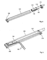
Fig. 9 is a perspective view of an exemplary embodiment of an assembled slide-on-rod mechanism according to this invention; -
Fig. 10 is a perspective view of an exemplary embodiment of a visor with the mechanism ofFig. 9 installed therein according to this invention; -
Fig. 11 is an exploded view of an exemplary embodiment of a pivot rod, detent spring, and carrier according to this invention; -
Fig. 12 is a partial cross-sectional view of an exemplary embodiment of a visor according to an exemplary embodiment of this invention; -
Fig. 13 is a schematic view of an exemplary embodiment of a visor according to a first exemplary embodiment according to this invention; -
Fig. 14 is a partial perspective end view of an exemplary embodiment of a channel according to a first exemplary embodiment according to this invention; -
Fig. 15 is an end view of an exemplary embodiment of a channel and carrier according to a second exemplary embodiment according to this invention; -
Fig. 16 is a partial end view of an exemplary embodiment of a channel according to a third exemplary embodiment according to this invention; -
Fig. 17 is an end view of an exemplary embodiment of a channel according to a fourth exemplary embodiment according to this invention; -
Fig. 18 is an end view of an exemplary embodiment of a channel and carrier according to fifth exemplary embodiment according to this invention; -
Fig. 19 is a perspective end view of an exemplary embodiment of a channel and carrier according to a sixth exemplary embodiment according to this invention; -
Fig. 20 is a perspective view of an exemplary embodiment of a carrier according to an exemplary embodiment according to this invention; -
Fig. 21 is a perspective end view of an exemplary embodiment of a channel and carrier assembly according to an exemplary embodiment according to this invention; -
Fig. 22 is a partial perspective view of a first exemplary embodiment of a closed channel according to this invention; -
Fig. 23 is a partial perspective view of a second exemplary embodiment of a closed channel according to this invention; -
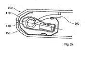
Fig. 24 is a partial end cross-sectional view of an exemplary embodiment of a pivot rod, carrier, channel and visor assembly with an electrical wire according to a first exemplary embodiment according to this invention; -
Fig. 25 is a partial cross-sectional end view of an exemplary embodiment of a pivot rod, carrier, and visor assembly according to a second exemplary embodiment according to this invention; -
Fig. 26 is a partial cross-sectional end view of an exemplary embodiment of a pivot rod; carrier, and visor assembly according to a third exemplary embodiment according to this invention; -
Fig. 27 is a partial cross-sectional end view of an exemplary embodiment of a pivot rod, carrier, and visor assembly according to a fourth exemplary embodiment according to this invention; -
Fig. 28 is a partial cross-sectional end view of an exemplary embodiment of a pivot rod, carrier, and visor assembly according to a fifth exemplary embodiment according to this invention; -
Fig. 29 is a perspective view of an exemplary embodiment of an outside end cap according to an exemplary embodiment according to this invention; -
Fig. 30 is a perspective view of an exemplary embodiment of an inside end cap according to this invention; -
Fig. 31 is a partial perspective view of a first exemplary embodiment of a visor body according to this invention; and -
Fig. 32 is a partial perspective view of a second exemplary embodiment of a visor body according to this invention. -
Fig. 33 shows the hemmed edge carrier fit -
Fig. 34 shows the end caps in the channel - This invention relates to a sliding sun visor for a vehicle. The disclosed designs provide a stamped or roll-formed channel that is less expensive to produce than prior art extruded aluminum channels. The disclosed sliding visor includes a carrier assembly attached to the pivot rod. The carrier assembly is fitted to a channel in the visor body. The carrier assembly slides along the channel, which allows the user to position the visor in a wider range of locations.
-
Fig. 1 shows an exemplary embodiment of avisor 100 in a detent or stowed position.Fig. 2 shows thevisor 100 ofFig. 1 rotated on apivot rod 110 to a downturned or in use position.Fig. 3 shows thevisor 100 ofFig. 1 in an in use position at the side window. -
Fig. 4 shows an exemplary embodiment of apivot rod 110,outside end cap 170,detent spring assembly 130,carrier 140, and spring loaded button 120. As shown inFig. 5 , thepivot rod 110 passes through theoutside end cap 170 and engages thedetent spring assembly 130. In various exemplary embodiments, as illustrated byFig. 24 , one ormore wires 160 pass through and out ofpivot rod 110. The one ormore wires 160 exit the through theopen channel 150 and provide a shorter electrical connection to components on the visor, such as, a vanity light. -
Figs. 7 and8 show the assembly ofFig. 24 and an exemplary embodiment of anopen channel 150 andinside end cap 180. As shown inFig. 27 , the detent spring slides into and along the channel. As shown infigure 8 , the spring loaded button 120 engageschannel 150 providing slide resistance. Theinside end cap 180 andoutside end cap 170 engage the channel at opposite ends. In various exemplary embodiments, theinside end cap 180 andoutside end cap 170 are engaged in thechannel 150 with a friction fit. Anopen channel 150 allows the one ormore wires 160 ingress and/or egress to the channel at any point along its length. -
Fig. 10 illustrates the installation of thechannel 150 and other components in anexemplary visor 100. Thechannel 150 engages the interior of thevisor 100 and may be fixedly attached thereto. The visor is closed over thechannel 150 and sealed. - In various exemplary embodiments, as illustrated in
Fig. 11 , the cross-section of thepivot rod 110 is approximately circular. In other exemplary embodiments, other symmetrical or asymmetrical shapes may be used. - In various exemplary embodiments, as shown in
Fig. 11 , the mechanism that allows thevisor 100 to slide relative to thepivot rod 110 and to rotate about thepivot rod 110 includes adetent spring assembly 130 attached to thepivot rod 110, and positioned around thecarrier 140. Thedetent spring assembly 130 provides compressive force on thepivot rod 110. Thedetent spring assembly 130 rotates or pivots relative to thepivot rod 110, permitting thevisor 100 to be moved between the stowed and the in use positions. The force on thepivot rod 110 provided by thedetent spring assembly 130 resists rotation, particularly in the detent position. As shown inFigs. 11 and 12 , thecarrier 140 fits into achannel 150 that is coupled to thevisor 100 body. In various exemplary embodiments, thecarrier 140 slides along thechannel 150, allowing thevisor 100 to slide relative to thepivot rod 110. In some exemplary embodiments, thecarrier 140 is force fit into thechannel 150 allowing thechannel 150 to flex and provide a means to reduce or eliminate looseness in the system. In some exemplary embodiments, thecarrier 140 has appendages 142 or a separate added spring 141 that flexes inside ofchannel 150, providing a means to reduce or eliminate looseness in the system. -
Fig. 13 shows an exemplary embodiment of avisor 100. Thepivot rod 110 is attached to adetent spring assembly 130 and is fitted to thecarrier 140. Thecarrier 140 slides alongchannel 150. - In various embodiments, the
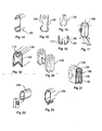
channel 150 may take a variety of shapes.Figs. 14-21 illustrate some of the various shapes that thechannel 150 andcarrier 140 may take. In some exemplary embodiments, thechannel 150 is not fully enclosed around its circumference, although the open portion may be very small. In various exemplary embodiments, thecarrier 140 has an external shape that is similar to, but not necessarily identical to, the interior shape of thechannel 150. The pieces are generally shaped such that they fit together, allowing thecarrier 140 to slide along the length of thechannel 150 without permitting appreciable movement in any other directions. - As shown in
Fig. 14 , in various exemplary embodiments, thechannel 150 is not fully enclosed. Thischannel 150 has a basic C-shaped profile. This embodiment also has a channel cross section with angled surfaces. The angled corners on the top allow the channel to fit into the top of the visor's rounded shape. The lower angled surfaces reduce side movement of the carrier during rotation. These angled surfaces can be rounded and provide the same function. Traditional extrusion methods produce a rounded top and flat bottom creating a "D" shaped cross section, which can also be the formed of a channel according to this invention. -
Fig. 15 shows another embodiment of achannel 150 andcarrier 140. Thechannel 150 is shaped to create a tight fit between thechannel 150 andcarrier 140. Referring toFig. 5 , in various exemplary embodiments, thechannel 150 has a shape adapted to contain at least a portion of thecarrier 140 within thechannel 150 and retain thecarrier 140 in thechannel 150 against force pulling thecarrier 140 away from thechannel 150. In various embodiments, thechannel 150 may or may not be symmetrical across a given axis.Fig. 16 illustrates a third embodiment of a channel. V-shaped retaining bends 155 are positioned to either side of an open space.Fig. 17 shows another embodiment with V-shaped retaining bends 155. InFig. 18 , the channel is shown with retaining bends 155.Fig. 19 illustrates another embodiment of achannel 150 with another embodiment of a retainingbend 155.Fig. 20 illustrates one embodiment of acarrier 140 adapted to work with achannel 150 such as the channel shown inFig. 18 . - Conventional C-shaped channels can flex and bend when the visor is rotated about the pivot rod, which causes the channel to open potentially allowing it to separate from the carrier.
Figs. 15-19 and 21 reduce or eliminate this problem with cross-sections having a shape that creates a force vector, during rotation, which forces the channel to close rather than open. This closing of the channel also reduces carrier movement and noise during rotation. -
Figs. 22 and 23 illustrate closed cross-section channels. In various exemplary embodiments, a closed channel may be manufactured by, for example, combining a toggle.lock (seeFig. 22 ) or a hem (seeFig. 23 ) with a stamped or roll-form process. Other examples of closed cross sections can created by extruding, welding, riveting, adhesive, or other similar processes of joining materials. - Frequently, visors include illuminated vanity mirrors and/or powered accessories, such as garage door opener transmitters, memo recorders, or other electrical accessories. Power to such accessories is typically provided via one or more wires that run into the vanity inside the visor pivot rod and channel. This requires a sufficient length of wires to reach the end of the channel and back to the one or more electrical accessories when the visor is fully extended, which is a significantly longer distance than a direct route.
- In some exemplary embodiments, as exemplified by
Fig. 24 , the selected shapes for thecarrier 140 and thechannel 150 are such that the selected shapes facilitate passage of one ormore wire 160 between the interior of thecarrier 140 and thevisor 100. Unlike other visor designs, the wire(s) 160 need not be long enough to extend the length of thepivot rod 110 plus the channel 150 (as when the visor is slid out to its full capacity). Instead, the wire(s) 160, which typically runs into thevisor 100 through the interior of thepivot rod 110, may exit thepivot rod 110 at any preselected point either within thecarrier 140 or at the end of thepivot rod 110 and pass through the opening in thechannel 150 to thevisor 100 core. In some exemplary embodiments, the wire(s) 160 exits thevisor pivot rod 110. Thus, the wire(s) 160 can be designed so that it is not affected by the movement of thevisor 100 relative to the pivot rod 110 (or, in other words, by the movement of thecarrier 140 relative to the channel 150). - Referring to
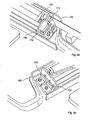
Figs. 25-28 , thechannel 150 and the visor core 101 (one half of visor core not shown) include a variety of attachment devices. Thevisor core 101 may includeribs 103 that impart structural strength. Thechannel 150 may be attached to theribs 130. One or more protrusions or hooks 102 may extend from theribs 103 or other portions of thevisor core 101. Thechannel 150 may include tabs orflanges 151 that attach to theribs 103 or hooks 102. Thechannel 150 may also include openings such as a slot orhole 153. Ahook 102 or other feature of thevisor core 101 may attach to the slot orhole 153. Referring toFig. 26 , thechannel 150 may include an indentation orchannel 154 that creates a tighter fit between thecarrier 140 and thechannel 150. - Referring now to
Figs. 29 and 30 , thevisor 100 is attached to anoutside end cap 170 and aninside end cap 180. In various embodiments, theoutside end cap 170 and theinside end cap 180 are each attached to the channel 150 (not shown) with a friction fit. Also, holes may be added to the ends of the channel into which the end caps may snap or tab.The end caps may rigidly attach to the channel with other conventional means such as heat stakes, screws, insert molding, adhesive bond, and/or the like. That is, ends of thechannel 150 are inserted into and mate with theoutside end cap 170 and theinside end cap 180.Fig. 29 shows one exemplary embodiment of anoutside end cap 170. Thepivot rod 110 passes through aguide 171 in theoutside end cap 170.Fig. 30 shows one exemplary embodiment of aninside end cap 180. The end caps 170 and 180 help keep thecarrier assembly 190 coupled to thechannel 150 and help define the limits of the ability of thevisor 100 to move relative to thepivot rod 110. Theoutside end cap 170 and theinside end cap 180 are attached to thevisor 100. This may be accomplished in various ways, including for example, screws, rivets, heat stakes, and the like. -
Fig. 31 shows a cross-section of a first exemplary embodiment of avisor 100 having multipleparallel ribs 103 and asingle rib 103 that is perpendicular to and connected to theparallel ribs 103. In the exemplary embodiment shown inFig. 31 , thesingle rib 103 has anarrow projection 102 down its length extending from the side of theattachment rib 103 opposite theparallel ribs 103. Thenarrow projection 102 may be supported by one or moretriangular gussets 106. Thenarrow projection 102 may be used to directly attach therib 103 to thechannel 150 or attach therib 103 via a flange 151 (Fig. 25 ) on thechannel 150. This attachment may also be made, for example, by friction fit under the projection, by bonding, by fasteners, and/or the like. -
Fig. 32 shows a cross-section of anothervisor 100 with multipleparallel ribs 103 and fourfurther hooks 104. The further hooks 104 are connected to a side of thevisor 100 and have two sides and a top defining a slot that opens on two ends. Thechannel 150 may be attached to thevisor 100 via the further hooks 104. This may be accomplished, for example, with tabs fitted into the slots, which may be secured by additional fastening mechanisms, such as, for example, friction fit, adhesives, fasteners, etc. Further, thefurther hooks 104 may be replaced with similar features formed by thevisor core 100 tooling through holes invisor core 100. The number of and location of the further hooks can be varied. - Prior art channels for SOR visors have typically had an enclosed shape and been made of aluminum extrusions or channels having multiple pieces. In various embodiments, a
channel 150 according to this invention is open rather than enclosed. In various embodiments, the channel is made of metal, but may be made of other materials of sufficient strength and durability to function as described above. In various embodiments, themetal channel 150 is roll formed. In various exemplary embodiments, thechannel 150 is formed by roll-forming a sheet of material. Alternative embodiments may be formed by other means. For example, thechannel 150 may be formed by molding and/or extruding a polymer. Other embodiments may be manufactured by processes such as stamping or thin wall extrusion. - According to various exemplary embodiments, the carrier may be preloaded in the channel to allow for larger tolerances and still have a tight fit. The channel opening "grips" the carrier and provides slide resistance as well as noise reduction throughout rotation and slide movement.
- According to various exemplary embodiments, the channel has angled surfaces that restrict carrier movement in the channel and act as a damper when motion does occur. Angled surfaces may be applied to any channel design, whether open or closed, or manufacturing processes, such as, for example, extruded, roll-formed, or stamped.
- It should be noted that references to relative positions (e.g., "top" and "bottom") in this description are merely used to identify various elements as are oriented in the figures. It should be recognized that the orientation of particular components may vary greatly depending on the application in which they are used.
- For the purpose of this disclosure, the terms "coupled" and/or "attached" means the joining of two members directly or indirectly to one another. Such joining may be stationary in nature or moveable in nature. Such joining may be achieved with the two members or the two members and any additional intermediate members being integrally formed as a single unitary body with one another or with the two members or the two members and any additional intermediate members being attached to one another. Such joining may be permanent in nature or may be removable or releasable in nature.
- As utilized herein, the terms "approximately," "about," "substantially," and similar terms are intended to have a broad meaning in harmony with the common and accepted usage by those of ordinary skill in the art to which the subject matter of this disclosure pertains. It should be understood by those of skill in the art who review this disclosure that these terms are intended to allow a description of certain features described and claimed without restricting the scope of these features to the precise numerical ranges provided. Accordingly, these terms should be interpreted as indicating that insubstantial or inconsequential modifications or alterations of the subject matter described and claimed are considered to be within the scope of the invention as recited in the appended claims.
- It should be understood that the drawings are not necessarily to scale. In certain instances, details that are not necessary to the understanding of the invention or render other details difficult to perceive may have been omitted. It should be understood, of course, that the invention is not necessarily limited to the particular embodiments illustrated herein.
- It is also important to note that the construction and arrangement of the elements of visor as shown in the exemplary embodiments is illustrative only. Although only a few exemplary embodiments according to this invention have been described in detail, it should be readily appreciated that many modifications are possible (e.g., variations in size, dimension, structure, shape, and proportion of the various elements; values of parameters; mounting arrangements; use or choice of materials, colors, orientations, etc.) without materially departing from the novel teachings and advantages of the subject matter recited. For example, elements shown as integrally formed may be constructed of multiple parts or elements shown as multiple parts may be integrally formed, the operation of the interfaces may be reversed or otherwise varied, the length or width of the structures and/or members or connector or other elements of the system may be varied, and/or the nature or number of adjustment positions provided between the elements may be varied (e.g., by variations in the number of engagement slots or size of the engagement slots or type of engagement): It should be noted that the elements and/or assemblies of the system may be constructed from any of a wide variety of colors, textures, and combinations. Accordingly, all such modifications are intended to be within the scope of the present disclosure. Other substitutions, modifications, changes, or omissions may be made in the design, operating conditions, and arrangement of the preferred and other exemplary embodiments without departing from the spirit of the present disclosure.
-
Fig. 33 shows thecarrier 140 inside thechannel 150. The edges of the channel are deflected in order to avoid sharp edges. One of the deflected edges is inserted into a groove, in the carrier. This optimizes the guidance of the carrier during its movement in the channel. Furthermore, the channel is slightly smaller than the carrier, so that the channel is, in defined regions, which are identified by arrows, pressed against the carrier. -
Fig. 34 depicts the visor core, which is made of two parts 101.1 and 101.2, which are sealed together. Both parts compriserips 200, which are, preferably arranged perpendicular to the channel and which fix the channel inside the core. As can also be seen fromfigure 34 , in the end region of the channel, end caps are inserted into the channel. Thewedges 300 of the end caps open the channel ends
Claims (14)
- Vehicle visor (100), comprising a solid or hollow visor pivot rod (110), a carrier (140) fitting to the visor pivot rod (110) and a spring mechanism (130), wherein the vehicle visor (100) slides relative to the pivot rod (110), wherein the spring mechanism (130) is at least partially in the carrier (140) and the vehicle visor (100) comprises a channel (150), whereas the carrier (140) slides along the channel (150), wherein the channel (150) is an open channel (150), characterized in that the cross-section of the carrier (140) is larger than the cross-section of the channel (150), wherein the carrier (140) fits inside the channel (150) with some interference that generates a resistive slide force.
- Vehicle visor (100) according to claim 1, characterized in that the channel (150) is fixed to the main body of the visor either directly or through the use of end caps (170, 180), whereas the carrier (140) is attached to the pivot rod (110) with the spring mechanism (130).
- Vehicle visor (100) according to one of the preceding claims, characterized in, that the spring mechanism (130) comprises a detent spring assembly, which provides a compressive force on the pivot rod (110).
- Vehicle visor (100) according to claim 3, characterized in, that the detent spring rotates or pivots relative to the pivot rod (110).
- Vehicle visor (100) according to one of the preceding claims, characterized in, that the carrier (140) has a slot that engages the edge of the channel (150), reducing rotational movement in the channel (150), preferably the slot has angled walls to keep the edge of the channel centered in the slot (150).
- Vehicle visor (100) according to one of the preceding claims, characterized in, that the carrier (140) has appendages or a separate added spring (141) that flexes inside the channel (150).
- Vehicle visor (100) according to one of the preceding claims, characterized in, that wires (160) pass through the pivot rod (110) and exit through the open side of the channel (150).
- Vehicle visor (100) according to one of the preceding claims, characterized In, that end stops are provided for the mounting of the carrier (140).
- Vehicle visor (100) according to claim 8, characterized In, that the end-stops are the end caps (170, 180).
- Vehicle visor (100) according to one of the preceding claims, characterized in, that the end caps (170, 180) provide datum surfaces for the ends of the channel.
- Vehicle visor (100) according to one of the preceding claims, characterized in, that it comprises a visor core (101), which comprises two parts, which are connected, preferably sealed together.
- Vehicle visor (100) according to one of the preceding claims, characterized in, that the pivot rod (110), the channel (150) and/or wire (160) are held in place by the visor core after the parts have been connected and/or that the end caps (170, 180) are held by the usage of screw fits, snap fits or the like.
- Vehicle visor (100) according one of preceding claims, characterized in, that at least one of the edges of the channel is rounded, preferably hemmed back over itself and/or rounded In order to avoid sharp edges in contact with the carrier.
- Vehicle visor (100) according to claim 13, characterized in, that the carrier (140) has a slot that fits over the hemmed or rounded edge of the channel.
Priority Applications (2)
| Application Number | Priority Date | Filing Date | Title |
|---|---|---|---|
| PL09744835T PL2347298T3 (en) | 2008-10-15 | 2009-10-15 | Slide-on-rod visors |
| EP13197136.8A EP2711760B1 (en) | 2008-10-15 | 2009-10-15 | Channel for slide-on-rod visors |
Applications Claiming Priority (3)
| Application Number | Priority Date | Filing Date | Title |
|---|---|---|---|
| US10568608P | 2008-10-15 | 2008-10-15 | |
| US11015408P | 2008-10-31 | 2008-10-31 | |
| PCT/US2009/060815 WO2010045438A1 (en) | 2008-10-15 | 2009-10-15 | Channel for slide-on-rod visors |
Related Child Applications (1)
| Application Number | Title | Priority Date | Filing Date |
|---|---|---|---|
| EP13197136.8A Division EP2711760B1 (en) | 2008-10-15 | 2009-10-15 | Channel for slide-on-rod visors |
Publications (2)
| Publication Number | Publication Date |
|---|---|
| EP2347298A1 EP2347298A1 (en) | 2011-07-27 |
| EP2347298B1 true EP2347298B1 (en) | 2014-01-01 |
Family
ID=41381868
Family Applications (2)
| Application Number | Title | Priority Date | Filing Date |
|---|---|---|---|
| EP09744835.1A Not-in-force EP2347298B1 (en) | 2008-10-15 | 2009-10-15 | Slide-on-rod visors |
| EP13197136.8A Not-in-force EP2711760B1 (en) | 2008-10-15 | 2009-10-15 | Channel for slide-on-rod visors |
Family Applications After (1)
| Application Number | Title | Priority Date | Filing Date |
|---|---|---|---|
| EP13197136.8A Not-in-force EP2711760B1 (en) | 2008-10-15 | 2009-10-15 | Channel for slide-on-rod visors |
Country Status (8)
| Country | Link |
|---|---|
| US (1) | US8434811B2 (en) |
| EP (2) | EP2347298B1 (en) |
| JP (2) | JP5542828B2 (en) |
| KR (2) | KR101477506B1 (en) |
| CN (1) | CN102216830B (en) |
| ES (1) | ES2456347T3 (en) |
| PL (1) | PL2347298T3 (en) |
| WO (1) | WO2010045438A1 (en) |
Families Citing this family (15)
| Publication number | Priority date | Publication date | Assignee | Title |
|---|---|---|---|---|
| PL2183130T3 (en) | 2007-07-27 | 2013-08-30 | Johnson Controls Tech Co | Composite headliner with improved acoustic performance |
| KR101477506B1 (en) * | 2008-10-15 | 2014-12-30 | 존슨 컨트롤스 테크놀러지 컴퍼니 | Channel for slide-on-rod visors |
| US8556325B2 (en) * | 2011-09-20 | 2013-10-15 | Irvin Automotive Products, Inc. | Sliding visor |
| TWI438476B (en) | 2012-01-12 | 2014-05-21 | Largan Precision Co Ltd | Image capturing system |
| JP2013248922A (en) * | 2012-05-30 | 2013-12-12 | Kyowa Sangyo Kk | Vehicular sun visor |
| DE102013209796A1 (en) * | 2012-05-30 | 2013-12-05 | Kyowa Sangyo Co., Ltd. | SUNSHADE FOR A VEHICLE |
| US10737559B2 (en) | 2014-12-16 | 2020-08-11 | Irvin Automotive Products, LLC | Visor |
| US10336165B2 (en) * | 2015-05-01 | 2019-07-02 | Ford Global Technologies, Llc | Spring-activated extendable sun visor blade |
| KR20170010251A (en) | 2015-07-17 | 2017-01-26 | (주)오토젠 | Hot press forming manufacturing method and mold therefor |
| EP3189995B1 (en) | 2015-12-16 | 2019-11-13 | Motus Integrated Technologies | Slide-on-rod assembly for a vehicle sun visor |
| EP3248820B1 (en) * | 2016-05-27 | 2020-02-12 | Grupo Antolin Ingenieria, S.A.U. | Sun visor with slide on rod function |
| US10688850B2 (en) | 2018-03-13 | 2020-06-23 | Irvin Automotive Products, LLC | Sliding visor |
| US10864804B2 (en) | 2019-02-28 | 2020-12-15 | Irvin Automotive Products, LLC | Sliding thin visor |
| US10870337B2 (en) | 2019-02-28 | 2020-12-22 | Irvin Automotive Products, LLC | Thin visor |
| KR20210109099A (en) * | 2020-02-26 | 2021-09-06 | 현대자동차주식회사 | Slim structure of sliding sun visor |
Family Cites Families (23)
| Publication number | Priority date | Publication date | Assignee | Title |
|---|---|---|---|---|
| JP3205043B2 (en) * | 1992-04-14 | 2001-09-04 | 株式会社ネオックスラボ | Sun visor for vehicles |
| US5409285A (en) * | 1994-04-18 | 1995-04-25 | Prince Corporation | Sliding visor |
| US5484183A (en) | 1995-01-05 | 1996-01-16 | Rosa; Thomas F. | Adjustable sun visor attachment |
| US5653490A (en) * | 1996-04-12 | 1997-08-05 | Prince Corporation | Sliding visor |
| US6010174A (en) * | 1997-04-14 | 2000-01-04 | Lear Automotive Dearborn, Inc. | Sliding visor |
| JP3335903B2 (en) * | 1998-05-13 | 2002-10-21 | 河西工業株式会社 | Sliding sun visor |
| DE10017046C1 (en) * | 2000-04-05 | 2001-06-13 | Johnson Contr Interiors Gmbh | Automobile sun visor has incorporated switch and garage door remote control device supplied via current lead fed through hollow pivot axis for sun visor body |
| JP2003220828A (en) * | 2002-01-30 | 2003-08-05 | Kyowa Sangyo Kk | Sun visor for vehicle |
| JP4187190B2 (en) * | 2002-06-06 | 2008-11-26 | 河西工業株式会社 | Sliding sun visor |
| DE10228103A1 (en) | 2002-06-24 | 2004-01-15 | Bayer Cropscience Ag | Fungicidal active ingredient combinations |
| US20040000062A1 (en) * | 2002-06-28 | 2004-01-01 | Johnson Controls Technology Company | Compass display for a vehicle |
| US6840561B2 (en) | 2002-10-02 | 2005-01-11 | Grupo Antolin Ingeniera, S.A. | Sun visor and cover attachment method |
| US6698814B1 (en) * | 2002-10-02 | 2004-03-02 | Grupo Antolin Ingenieria, S.A. | Slidable sun visor |
| EP1556235A4 (en) * | 2002-10-02 | 2010-09-15 | Johnson Controls Tech Co | Sliding visor |
| US6923490B2 (en) * | 2003-01-24 | 2005-08-02 | Lear Corporation | Slidable sun visor assembly |
| ES2265215B1 (en) * | 2004-03-10 | 2007-11-01 | Intier Automotive Interiors Zippex, S.A.U. | EXTENSIBLE PARASOL PERFECTED FOR VEHICLES. |
| US7032949B1 (en) | 2004-12-08 | 2006-04-25 | General Motors Corporation | Sun visor assembly |
| ES2302158T3 (en) * | 2005-03-01 | 2008-07-01 | Grupo Antolin-Ingenieria, S.A. | PARASOL ASSEMBLY. |
| WO2006123504A1 (en) * | 2005-05-18 | 2006-11-23 | Kyowa Sangyo Co., Ltd. | Sun visor for vehicle |
| JP2007131168A (en) * | 2005-11-10 | 2007-05-31 | Kyowa Sangyo Kk | Sun visor for vehicle |
| WO2010000020A1 (en) | 2008-06-30 | 2010-01-07 | Cathrx Ltd | A catheter |
| US7798551B2 (en) * | 2008-07-15 | 2010-09-21 | Kasai Kogyo Co., Ltd. | Vehicle-mountable sun visor |
| KR101477506B1 (en) | 2008-10-15 | 2014-12-30 | 존슨 컨트롤스 테크놀러지 컴퍼니 | Channel for slide-on-rod visors |
-
2009
- 2009-10-15 KR KR1020117009969A patent/KR101477506B1/en active IP Right Grant
- 2009-10-15 KR KR1020137029703A patent/KR101595715B1/en active IP Right Grant
- 2009-10-15 WO PCT/US2009/060815 patent/WO2010045438A1/en active Application Filing
- 2009-10-15 PL PL09744835T patent/PL2347298T3/en unknown
- 2009-10-15 EP EP09744835.1A patent/EP2347298B1/en not_active Not-in-force
- 2009-10-15 JP JP2011532243A patent/JP5542828B2/en not_active Expired - Fee Related
- 2009-10-15 ES ES09744835.1T patent/ES2456347T3/en active Active
- 2009-10-15 CN CN200980146104.0A patent/CN102216830B/en active Active
- 2009-10-15 US US13/123,430 patent/US8434811B2/en not_active Expired - Fee Related
- 2009-10-15 EP EP13197136.8A patent/EP2711760B1/en not_active Not-in-force
-
2014
- 2014-03-10 JP JP2014046710A patent/JP6131206B2/en active Active
Also Published As
| Publication number | Publication date |
|---|---|
| KR20130128487A (en) | 2013-11-26 |
| KR101595715B1 (en) | 2016-02-26 |
| EP2347298A1 (en) | 2011-07-27 |
| WO2010045438A1 (en) | 2010-04-22 |
| JP6131206B2 (en) | 2017-05-17 |
| JP2014131910A (en) | 2014-07-17 |
| CN102216830A (en) | 2011-10-12 |
| JP2012505794A (en) | 2012-03-08 |
| KR101477506B1 (en) | 2014-12-30 |
| JP5542828B2 (en) | 2014-07-09 |
| PL2347298T3 (en) | 2014-05-30 |
| EP2711760B1 (en) | 2017-01-18 |
| KR20110075003A (en) | 2011-07-05 |
| EP2711760A1 (en) | 2014-03-26 |
| ES2456347T3 (en) | 2014-04-22 |
| US20110227362A1 (en) | 2011-09-22 |
| US8434811B2 (en) | 2013-05-07 |
| CN102216830B (en) | 2015-07-15 |
Similar Documents
| Publication | Publication Date | Title |
|---|---|---|
| EP2347298B1 (en) | Slide-on-rod visors | |
| US5864987A (en) | Window regulator with improved glider assembly | |
| US7694712B2 (en) | Window shade with coil spring drive | |
| US5645308A (en) | Sliding visor | |
| US7441833B1 (en) | Arrangement and method for converting of single panel sunroofs into double panel sunroofs and component parts thereof | |
| US6174019B1 (en) | Extruded visor control | |
| US7987554B2 (en) | Hinge structure for vehicle open/close body | |
| US20070144690A1 (en) | Roller blind with simplified assembly of the wind-up shaft | |
| KR20060134838A (en) | Rear-window roller blind with complete slit coverage by the pull-out profile | |
| EP2514618A2 (en) | Sheet winding apparatus for vehicle | |
| EP2623347A1 (en) | Vehicle sunshade | |
| JP4621501B2 (en) | Sliding sun visor | |
| US5822921A (en) | Door with biasing window regulator | |
| JP2013230752A (en) | Installation structure of retractor of sunshade device for vehicle | |
| JP2013096209A (en) | Window regulator device for vehicle | |
| US20090160208A1 (en) | Vehicle visor assembly | |
| JP6811356B2 (en) | Vehicle sun visor | |
| US6926336B1 (en) | Sun visor assembly | |
| CN219446694U (en) | Curtain assembly | |
| JP2013096208A (en) | Window regulator device for vehicle | |
| JP5486453B2 (en) | Vehicle door sash structure | |
| JPH0329211Y2 (en) | ||
| JP6543521B2 (en) | Mounting structure of automotive door seal | |
| JPH0318623Y2 (en) | ||
| JP5902472B2 (en) | Sunshade equipment |
Legal Events
| Date | Code | Title | Description |
|---|---|---|---|
| PUAI | Public reference made under article 153(3) epc to a published international application that has entered the european phase |
Free format text: ORIGINAL CODE: 0009012 |
|
| 17P | Request for examination filed |
Effective date: 20110516 |
|
| AK | Designated contracting states |
Kind code of ref document: A1 Designated state(s): AT BE BG CH CY CZ DE DK EE ES FI FR GB GR HR HU IE IS IT LI LT LU LV MC MK MT NL NO PL PT RO SE SI SK SM TR |
|
| AX | Request for extension of the european patent |
Extension state: AL BA RS |
|
| DAX | Request for extension of the european patent (deleted) | ||
| 17Q | First examination report despatched |
Effective date: 20130110 |
|
| GRAP | Despatch of communication of intention to grant a patent |
Free format text: ORIGINAL CODE: EPIDOSNIGR1 |
|
| INTG | Intention to grant announced |
Effective date: 20130809 |
|
| GRAS | Grant fee paid |
Free format text: ORIGINAL CODE: EPIDOSNIGR3 |
|
| GRAA | (expected) grant |
Free format text: ORIGINAL CODE: 0009210 |
|
| AK | Designated contracting states |
Kind code of ref document: B1 Designated state(s): AT BE BG CH CY CZ DE DK EE ES FI FR GB GR HR HU IE IS IT LI LT LU LV MC MK MT NL NO PL PT RO SE SI SK SM TR |
|
| REG | Reference to a national code |
Ref country code: GB Ref legal event code: FG4D |
|
| REG | Reference to a national code |
Ref country code: CH Ref legal event code: EP |
|
| REG | Reference to a national code |
Ref country code: IE Ref legal event code: FG4D |
|
| REG | Reference to a national code |
Ref country code: DE Ref legal event code: R096 Ref document number: 602009021156 Country of ref document: DE Effective date: 20140213 |
|
| REG | Reference to a national code |
Ref country code: AT Ref legal event code: REF Ref document number: 647835 Country of ref document: AT Kind code of ref document: T Effective date: 20140215 |
|
| REG | Reference to a national code |
Ref country code: ES Ref legal event code: FG2A Ref document number: 2456347 Country of ref document: ES Kind code of ref document: T3 Effective date: 20140422 |
|
| REG | Reference to a national code |
Ref country code: NL Ref legal event code: VDEP Effective date: 20140101 |
|
| REG | Reference to a national code |
Ref country code: AT Ref legal event code: MK05 Ref document number: 647835 Country of ref document: AT Kind code of ref document: T Effective date: 20140101 |
|
| REG | Reference to a national code |
Ref country code: PL Ref legal event code: T3 |
|
| REG | Reference to a national code |
Ref country code: LT Ref legal event code: MG4D |
|
| PG25 | Lapsed in a contracting state [announced via postgrant information from national office to epo] |
Ref country code: LT Free format text: LAPSE BECAUSE OF FAILURE TO SUBMIT A TRANSLATION OF THE DESCRIPTION OR TO PAY THE FEE WITHIN THE PRESCRIBED TIME-LIMIT Effective date: 20140101 Ref country code: IS Free format text: LAPSE BECAUSE OF FAILURE TO SUBMIT A TRANSLATION OF THE DESCRIPTION OR TO PAY THE FEE WITHIN THE PRESCRIBED TIME-LIMIT Effective date: 20140501 |
|
| PG25 | Lapsed in a contracting state [announced via postgrant information from national office to epo] |
Ref country code: FI Free format text: LAPSE BECAUSE OF FAILURE TO SUBMIT A TRANSLATION OF THE DESCRIPTION OR TO PAY THE FEE WITHIN THE PRESCRIBED TIME-LIMIT Effective date: 20140101 Ref country code: SE Free format text: LAPSE BECAUSE OF FAILURE TO SUBMIT A TRANSLATION OF THE DESCRIPTION OR TO PAY THE FEE WITHIN THE PRESCRIBED TIME-LIMIT Effective date: 20140101 Ref country code: CY Free format text: LAPSE BECAUSE OF FAILURE TO SUBMIT A TRANSLATION OF THE DESCRIPTION OR TO PAY THE FEE WITHIN THE PRESCRIBED TIME-LIMIT Effective date: 20140101 Ref country code: PT Free format text: LAPSE BECAUSE OF FAILURE TO SUBMIT A TRANSLATION OF THE DESCRIPTION OR TO PAY THE FEE WITHIN THE PRESCRIBED TIME-LIMIT Effective date: 20140502 Ref country code: AT Free format text: LAPSE BECAUSE OF FAILURE TO SUBMIT A TRANSLATION OF THE DESCRIPTION OR TO PAY THE FEE WITHIN THE PRESCRIBED TIME-LIMIT Effective date: 20140101 Ref country code: NL Free format text: LAPSE BECAUSE OF FAILURE TO SUBMIT A TRANSLATION OF THE DESCRIPTION OR TO PAY THE FEE WITHIN THE PRESCRIBED TIME-LIMIT Effective date: 20140101 |
|
| PG25 | Lapsed in a contracting state [announced via postgrant information from national office to epo] |
Ref country code: LV Free format text: LAPSE BECAUSE OF FAILURE TO SUBMIT A TRANSLATION OF THE DESCRIPTION OR TO PAY THE FEE WITHIN THE PRESCRIBED TIME-LIMIT Effective date: 20140101 Ref country code: BE Free format text: LAPSE BECAUSE OF FAILURE TO SUBMIT A TRANSLATION OF THE DESCRIPTION OR TO PAY THE FEE WITHIN THE PRESCRIBED TIME-LIMIT Effective date: 20140101 Ref country code: HR Free format text: LAPSE BECAUSE OF FAILURE TO SUBMIT A TRANSLATION OF THE DESCRIPTION OR TO PAY THE FEE WITHIN THE PRESCRIBED TIME-LIMIT Effective date: 20140101 |
|
| REG | Reference to a national code |
Ref country code: DE Ref legal event code: R097 Ref document number: 602009021156 Country of ref document: DE |
|
| PG25 | Lapsed in a contracting state [announced via postgrant information from national office to epo] |
Ref country code: DK Free format text: LAPSE BECAUSE OF FAILURE TO SUBMIT A TRANSLATION OF THE DESCRIPTION OR TO PAY THE FEE WITHIN THE PRESCRIBED TIME-LIMIT Effective date: 20140101 Ref country code: RO Free format text: LAPSE BECAUSE OF FAILURE TO SUBMIT A TRANSLATION OF THE DESCRIPTION OR TO PAY THE FEE WITHIN THE PRESCRIBED TIME-LIMIT Effective date: 20140101 Ref country code: CZ Free format text: LAPSE BECAUSE OF FAILURE TO SUBMIT A TRANSLATION OF THE DESCRIPTION OR TO PAY THE FEE WITHIN THE PRESCRIBED TIME-LIMIT Effective date: 20140101 Ref country code: EE Free format text: LAPSE BECAUSE OF FAILURE TO SUBMIT A TRANSLATION OF THE DESCRIPTION OR TO PAY THE FEE WITHIN THE PRESCRIBED TIME-LIMIT Effective date: 20140101 |
|
| PLBE | No opposition filed within time limit |
Free format text: ORIGINAL CODE: 0009261 |
|
| STAA | Information on the status of an ep patent application or granted ep patent |
Free format text: STATUS: NO OPPOSITION FILED WITHIN TIME LIMIT |
|
| REG | Reference to a national code |
Ref country code: DE Ref legal event code: R082 Ref document number: 602009021156 Country of ref document: DE Representative=s name: MEISSNER BOLTE PATENTANWAELTE RECHTSANWAELTE P, DE Ref country code: DE Ref legal event code: R082 Ref document number: 602009021156 Country of ref document: DE Representative=s name: MEISSNER, BOLTE & PARTNER GBR, DE |
|
| PG25 | Lapsed in a contracting state [announced via postgrant information from national office to epo] |
Ref country code: SK Free format text: LAPSE BECAUSE OF FAILURE TO SUBMIT A TRANSLATION OF THE DESCRIPTION OR TO PAY THE FEE WITHIN THE PRESCRIBED TIME-LIMIT Effective date: 20140101 |
|
| 26N | No opposition filed |
Effective date: 20141002 |
|
| REG | Reference to a national code |
Ref country code: DE Ref legal event code: R097 Ref document number: 602009021156 Country of ref document: DE Effective date: 20141002 |
|
| REG | Reference to a national code |
Ref country code: DE Ref legal event code: R082 Ref document number: 602009021156 Country of ref document: DE Representative=s name: MEISSNER, BOLTE & PARTNER GBR, DE Ref country code: DE Ref legal event code: R082 Ref document number: 602009021156 Country of ref document: DE Representative=s name: MEISSNER BOLTE PATENTANWAELTE RECHTSANWAELTE P, DE |
|
| PG25 | Lapsed in a contracting state [announced via postgrant information from national office to epo] |
Ref country code: MC Free format text: LAPSE BECAUSE OF FAILURE TO SUBMIT A TRANSLATION OF THE DESCRIPTION OR TO PAY THE FEE WITHIN THE PRESCRIBED TIME-LIMIT Effective date: 20140101 Ref country code: LU Free format text: LAPSE BECAUSE OF FAILURE TO SUBMIT A TRANSLATION OF THE DESCRIPTION OR TO PAY THE FEE WITHIN THE PRESCRIBED TIME-LIMIT Effective date: 20141015 Ref country code: SI Free format text: LAPSE BECAUSE OF FAILURE TO SUBMIT A TRANSLATION OF THE DESCRIPTION OR TO PAY THE FEE WITHIN THE PRESCRIBED TIME-LIMIT Effective date: 20140101 |
|
| REG | Reference to a national code |
Ref country code: CH Ref legal event code: PL |
|
| GBPC | Gb: european patent ceased through non-payment of renewal fee |
Effective date: 20141015 |
|
| REG | Reference to a national code |
Ref country code: IE Ref legal event code: MM4A |
|
| PG25 | Lapsed in a contracting state [announced via postgrant information from national office to epo] |
Ref country code: GB Free format text: LAPSE BECAUSE OF NON-PAYMENT OF DUE FEES Effective date: 20141015 Ref country code: CH Free format text: LAPSE BECAUSE OF NON-PAYMENT OF DUE FEES Effective date: 20141031 Ref country code: LI Free format text: LAPSE BECAUSE OF NON-PAYMENT OF DUE FEES Effective date: 20141031 |
|
| PG25 | Lapsed in a contracting state [announced via postgrant information from national office to epo] |
Ref country code: IE Free format text: LAPSE BECAUSE OF NON-PAYMENT OF DUE FEES Effective date: 20141015 |
|
| REG | Reference to a national code |
Ref country code: FR Ref legal event code: PLFP Year of fee payment: 7 |
|
| PG25 | Lapsed in a contracting state [announced via postgrant information from national office to epo] |
Ref country code: NO Free format text: LAPSE BECAUSE OF FAILURE TO SUBMIT A TRANSLATION OF THE DESCRIPTION OR TO PAY THE FEE WITHIN THE PRESCRIBED TIME-LIMIT Effective date: 20140401 Ref country code: SM Free format text: LAPSE BECAUSE OF FAILURE TO SUBMIT A TRANSLATION OF THE DESCRIPTION OR TO PAY THE FEE WITHIN THE PRESCRIBED TIME-LIMIT Effective date: 20140101 |
|
| PG25 | Lapsed in a contracting state [announced via postgrant information from national office to epo] |
Ref country code: IT Free format text: LAPSE BECAUSE OF FAILURE TO SUBMIT A TRANSLATION OF THE DESCRIPTION OR TO PAY THE FEE WITHIN THE PRESCRIBED TIME-LIMIT Effective date: 20140101 Ref country code: BG Free format text: LAPSE BECAUSE OF FAILURE TO SUBMIT A TRANSLATION OF THE DESCRIPTION OR TO PAY THE FEE WITHIN THE PRESCRIBED TIME-LIMIT Effective date: 20140101 Ref country code: GR Free format text: LAPSE BECAUSE OF FAILURE TO SUBMIT A TRANSLATION OF THE DESCRIPTION OR TO PAY THE FEE WITHIN THE PRESCRIBED TIME-LIMIT Effective date: 20140402 |
|
| PG25 | Lapsed in a contracting state [announced via postgrant information from national office to epo] |
Ref country code: MT Free format text: LAPSE BECAUSE OF FAILURE TO SUBMIT A TRANSLATION OF THE DESCRIPTION OR TO PAY THE FEE WITHIN THE PRESCRIBED TIME-LIMIT Effective date: 20140101 Ref country code: HU Free format text: LAPSE BECAUSE OF FAILURE TO SUBMIT A TRANSLATION OF THE DESCRIPTION OR TO PAY THE FEE WITHIN THE PRESCRIBED TIME-LIMIT; INVALID AB INITIO Effective date: 20091015 Ref country code: TR Free format text: LAPSE BECAUSE OF FAILURE TO SUBMIT A TRANSLATION OF THE DESCRIPTION OR TO PAY THE FEE WITHIN THE PRESCRIBED TIME-LIMIT Effective date: 20140101 |
|
| REG | Reference to a national code |
Ref country code: FR Ref legal event code: PLFP Year of fee payment: 8 |
|
| REG | Reference to a national code |
Ref country code: FR Ref legal event code: PLFP Year of fee payment: 9 |
|
| PGFP | Annual fee paid to national office [announced via postgrant information from national office to epo] |
Ref country code: PL Payment date: 20170925 Year of fee payment: 9 |
|
| PGFP | Annual fee paid to national office [announced via postgrant information from national office to epo] |
Ref country code: ES Payment date: 20171121 Year of fee payment: 9 |
|
| PG25 | Lapsed in a contracting state [announced via postgrant information from national office to epo] |
Ref country code: MK Free format text: LAPSE BECAUSE OF FAILURE TO SUBMIT A TRANSLATION OF THE DESCRIPTION OR TO PAY THE FEE WITHIN THE PRESCRIBED TIME-LIMIT Effective date: 20140101 |
|
| REG | Reference to a national code |
Ref country code: FR Ref legal event code: PLFP Year of fee payment: 10 |
|
| REG | Reference to a national code |
Ref country code: ES Ref legal event code: FD2A Effective date: 20191202 |
|
| PG25 | Lapsed in a contracting state [announced via postgrant information from national office to epo] |
Ref country code: ES Free format text: LAPSE BECAUSE OF NON-PAYMENT OF DUE FEES Effective date: 20181016 |
|
| PG25 | Lapsed in a contracting state [announced via postgrant information from national office to epo] |
Ref country code: PL Free format text: LAPSE BECAUSE OF NON-PAYMENT OF DUE FEES Effective date: 20181015 |
|
| PGFP | Annual fee paid to national office [announced via postgrant information from national office to epo] |
Ref country code: FR Payment date: 20220413 Year of fee payment: 13 Ref country code: DE Payment date: 20220423 Year of fee payment: 13 |
|
| REG | Reference to a national code |
Ref country code: DE Ref legal event code: R119 Ref document number: 602009021156 Country of ref document: DE |
|
| PG25 | Lapsed in a contracting state [announced via postgrant information from national office to epo] |
Ref country code: FR Free format text: LAPSE BECAUSE OF NON-PAYMENT OF DUE FEES Effective date: 20221031 Ref country code: DE Free format text: LAPSE BECAUSE OF NON-PAYMENT OF DUE FEES Effective date: 20230503 |