EP2346252A1 - Image processing apparatus and method - Google Patents
Image processing apparatus and method Download PDFInfo
- Publication number
- EP2346252A1 EP2346252A1 EP20110150768 EP11150768A EP2346252A1 EP 2346252 A1 EP2346252 A1 EP 2346252A1 EP 20110150768 EP20110150768 EP 20110150768 EP 11150768 A EP11150768 A EP 11150768A EP 2346252 A1 EP2346252 A1 EP 2346252A1
- Authority
- EP
- European Patent Office
- Prior art keywords
- code stream
- characteristic amount
- divisional
- packet
- resolution
- Prior art date
- Legal status (The legal status is an assumption and is not a legal conclusion. Google has not performed a legal analysis and makes no representation as to the accuracy of the status listed.)
- Ceased
Links
Images


Classifications
-
- H—ELECTRICITY
- H04—ELECTRIC COMMUNICATION TECHNIQUE
- H04N—PICTORIAL COMMUNICATION, e.g. TELEVISION
- H04N19/00—Methods or arrangements for coding, decoding, compressing or decompressing digital video signals
- H04N19/10—Methods or arrangements for coding, decoding, compressing or decompressing digital video signals using adaptive coding
- H04N19/134—Methods or arrangements for coding, decoding, compressing or decompressing digital video signals using adaptive coding characterised by the element, parameter or criterion affecting or controlling the adaptive coding
- H04N19/146—Data rate or code amount at the encoder output
-
- H—ELECTRICITY
- H04—ELECTRIC COMMUNICATION TECHNIQUE
- H04N—PICTORIAL COMMUNICATION, e.g. TELEVISION
- H04N21/00—Selective content distribution, e.g. interactive television or video on demand [VOD]
- H04N21/20—Servers specifically adapted for the distribution of content, e.g. VOD servers; Operations thereof
- H04N21/23—Processing of content or additional data; Elementary server operations; Server middleware
- H04N21/231—Content storage operation, e.g. caching movies for short term storage, replicating data over plural servers, prioritizing data for deletion
- H04N21/23106—Content storage operation, e.g. caching movies for short term storage, replicating data over plural servers, prioritizing data for deletion involving caching operations
-
- H—ELECTRICITY
- H04—ELECTRIC COMMUNICATION TECHNIQUE
- H04N—PICTORIAL COMMUNICATION, e.g. TELEVISION
- H04N19/00—Methods or arrangements for coding, decoding, compressing or decompressing digital video signals
- H04N19/10—Methods or arrangements for coding, decoding, compressing or decompressing digital video signals using adaptive coding
- H04N19/102—Methods or arrangements for coding, decoding, compressing or decompressing digital video signals using adaptive coding characterised by the element, parameter or selection affected or controlled by the adaptive coding
- H04N19/115—Selection of the code volume for a coding unit prior to coding
-
- H—ELECTRICITY
- H04—ELECTRIC COMMUNICATION TECHNIQUE
- H04N—PICTORIAL COMMUNICATION, e.g. TELEVISION
- H04N19/00—Methods or arrangements for coding, decoding, compressing or decompressing digital video signals
- H04N19/10—Methods or arrangements for coding, decoding, compressing or decompressing digital video signals using adaptive coding
- H04N19/169—Methods or arrangements for coding, decoding, compressing or decompressing digital video signals using adaptive coding characterised by the coding unit, i.e. the structural portion or semantic portion of the video signal being the object or the subject of the adaptive coding
- H04N19/188—Methods or arrangements for coding, decoding, compressing or decompressing digital video signals using adaptive coding characterised by the coding unit, i.e. the structural portion or semantic portion of the video signal being the object or the subject of the adaptive coding the unit being a video data packet, e.g. a network abstraction layer [NAL] unit
-
- H—ELECTRICITY
- H04—ELECTRIC COMMUNICATION TECHNIQUE
- H04N—PICTORIAL COMMUNICATION, e.g. TELEVISION
- H04N19/00—Methods or arrangements for coding, decoding, compressing or decompressing digital video signals
- H04N19/10—Methods or arrangements for coding, decoding, compressing or decompressing digital video signals using adaptive coding
- H04N19/189—Methods or arrangements for coding, decoding, compressing or decompressing digital video signals using adaptive coding characterised by the adaptation method, adaptation tool or adaptation type used for the adaptive coding
- H04N19/196—Methods or arrangements for coding, decoding, compressing or decompressing digital video signals using adaptive coding characterised by the adaptation method, adaptation tool or adaptation type used for the adaptive coding being specially adapted for the computation of encoding parameters, e.g. by averaging previously computed encoding parameters
-
- H—ELECTRICITY
- H04—ELECTRIC COMMUNICATION TECHNIQUE
- H04N—PICTORIAL COMMUNICATION, e.g. TELEVISION
- H04N19/00—Methods or arrangements for coding, decoding, compressing or decompressing digital video signals
- H04N19/30—Methods or arrangements for coding, decoding, compressing or decompressing digital video signals using hierarchical techniques, e.g. scalability
- H04N19/34—Scalability techniques involving progressive bit-plane based encoding of the enhancement layer, e.g. fine granular scalability [FGS]
-
- H—ELECTRICITY
- H04—ELECTRIC COMMUNICATION TECHNIQUE
- H04N—PICTORIAL COMMUNICATION, e.g. TELEVISION
- H04N19/00—Methods or arrangements for coding, decoding, compressing or decompressing digital video signals
- H04N19/60—Methods or arrangements for coding, decoding, compressing or decompressing digital video signals using transform coding
- H04N19/63—Methods or arrangements for coding, decoding, compressing or decompressing digital video signals using transform coding using sub-band based transform, e.g. wavelets
-
- H—ELECTRICITY
- H04—ELECTRIC COMMUNICATION TECHNIQUE
- H04N—PICTORIAL COMMUNICATION, e.g. TELEVISION
- H04N19/00—Methods or arrangements for coding, decoding, compressing or decompressing digital video signals
- H04N19/70—Methods or arrangements for coding, decoding, compressing or decompressing digital video signals characterised by syntax aspects related to video coding, e.g. related to compression standards
-
- H—ELECTRICITY
- H04—ELECTRIC COMMUNICATION TECHNIQUE
- H04N—PICTORIAL COMMUNICATION, e.g. TELEVISION
- H04N21/00—Selective content distribution, e.g. interactive television or video on demand [VOD]
- H04N21/20—Servers specifically adapted for the distribution of content, e.g. VOD servers; Operations thereof
- H04N21/23—Processing of content or additional data; Elementary server operations; Server middleware
- H04N21/234—Processing of video elementary streams, e.g. splicing of video streams or manipulating encoded video stream scene graphs
- H04N21/2343—Processing of video elementary streams, e.g. splicing of video streams or manipulating encoded video stream scene graphs involving reformatting operations of video signals for distribution or compliance with end-user requests or end-user device requirements
- H04N21/234327—Processing of video elementary streams, e.g. splicing of video streams or manipulating encoded video stream scene graphs involving reformatting operations of video signals for distribution or compliance with end-user requests or end-user device requirements by decomposing into layers, e.g. base layer and one or more enhancement layers
-
- H—ELECTRICITY
- H04—ELECTRIC COMMUNICATION TECHNIQUE
- H04N—PICTORIAL COMMUNICATION, e.g. TELEVISION
- H04N21/00—Selective content distribution, e.g. interactive television or video on demand [VOD]
- H04N21/20—Servers specifically adapted for the distribution of content, e.g. VOD servers; Operations thereof
- H04N21/23—Processing of content or additional data; Elementary server operations; Server middleware
- H04N21/238—Interfacing the downstream path of the transmission network, e.g. adapting the transmission rate of a video stream to network bandwidth; Processing of multiplex streams
- H04N21/2381—Adapting the multiplex stream to a specific network, e.g. an Internet Protocol [IP] network
-
- H—ELECTRICITY
- H04—ELECTRIC COMMUNICATION TECHNIQUE
- H04N—PICTORIAL COMMUNICATION, e.g. TELEVISION
- H04N21/00—Selective content distribution, e.g. interactive television or video on demand [VOD]
- H04N21/20—Servers specifically adapted for the distribution of content, e.g. VOD servers; Operations thereof
- H04N21/25—Management operations performed by the server for facilitating the content distribution or administrating data related to end-users or client devices, e.g. end-user or client device authentication, learning user preferences for recommending movies
- H04N21/266—Channel or content management, e.g. generation and management of keys and entitlement messages in a conditional access system, merging a VOD unicast channel into a multicast channel
- H04N21/2662—Controlling the complexity of the video stream, e.g. by scaling the resolution or bitrate of the video stream based on the client capabilities
-
- H—ELECTRICITY
- H04—ELECTRIC COMMUNICATION TECHNIQUE
- H04N—PICTORIAL COMMUNICATION, e.g. TELEVISION
- H04N21/00—Selective content distribution, e.g. interactive television or video on demand [VOD]
- H04N21/40—Client devices specifically adapted for the reception of or interaction with content, e.g. set-top-box [STB]; Operations thereof
- H04N21/43—Processing of content or additional data, e.g. demultiplexing additional data from a digital video stream; Elementary client operations, e.g. monitoring of home network or synchronising decoder's clock; Client middleware
- H04N21/436—Interfacing a local distribution network, e.g. communicating with another STB or one or more peripheral devices inside the home
- H04N21/4363—Adapting the video stream to a specific local network, e.g. a Bluetooth® network
-
- H—ELECTRICITY
- H04—ELECTRIC COMMUNICATION TECHNIQUE
- H04N—PICTORIAL COMMUNICATION, e.g. TELEVISION
- H04N21/00—Selective content distribution, e.g. interactive television or video on demand [VOD]
- H04N21/40—Client devices specifically adapted for the reception of or interaction with content, e.g. set-top-box [STB]; Operations thereof
- H04N21/43—Processing of content or additional data, e.g. demultiplexing additional data from a digital video stream; Elementary client operations, e.g. monitoring of home network or synchronising decoder's clock; Client middleware
- H04N21/438—Interfacing the downstream path of the transmission network originating from a server, e.g. retrieving encoded video stream packets from an IP network
- H04N21/4381—Recovering the multiplex stream from a specific network, e.g. recovering MPEG packets from ATM cells
Definitions
- This invention relates to an image processing apparatus and method.
- JPEG 2000 (Joint Photographic Experts Group 2000) standardized by ISO (International Organization for Standardization)/IEC (International Electrotechnical Commission) in 2000 has such various characteristics that it allows encoding in high compressibility, that it is ready for both of reversible compression and irreversible compression, that it allows encoding so that the resolution or the picture quality is improved by scalability and that it allows encoding so as to enhance the error resisting property.
- JPEG 2000 is expected as an alternative technique of JPEG (refer to, for example, Japanese Patent Laid-Open No. 2006-311327 ).
- JPEG 2000 Part-1 was selected as a standard codec by the standard for digital cinema (DCI (Digital Cinema Initiatives). This made it possible to standardize the encoding methods from image pickup to image editing and image distribution of digital cinema with JPEG 2000.
- DCI Digital Cinema Initiatives
- Embodiments of the present invention relate to an image processing apparatus and method by which necessary data can be obtained in response to a desired characteristic amount.
- an image processing apparatus including header information production means for producing, regarding each of divisional code streams obtained by dividing a code stream having a structure of a progression order produced by coding image data, header information at a start and an end of the divisional code stream, the header information including a characteristic amount of an image of the image data, and packet production means for converting each of the divisional code streams into a packet using the header information produced by the header information production means.
- the image processing apparatus further includes coding means for coding the image data to produce the code stream having a structure of the progression order, the header information production means producing the header information for each of the divisional code streams obtained by dividing the code stream produced by coding the image data by the coding means.
- the image processing apparatus further includes dividing means for dividing the code stream produced by coding the image data by means of the coding means for each of predetermined data lengths, the header information production means producing the header information for each of the divisional code streams obtained by dividing the code stream by means of the dividing means.
- the code stream may be obtained by coding the image data using the JPEG 2000 system.
- the characteristic amount may include resolution and a layer according to the JPEG 2000 system.
- the progression order has a hierarchical structure of at least two hierarchies, and a variable of the upper hierarchy is the resolution and a variable of the lower hierarchy is the layer or the variable of the upper hierarchy is the layer and the variable of the lower hierarchy is the resolution.
- the header information production means may include extraction means for extracting a start address and an end address of each of the divisional code streams, characteristic amount calculation means for calculating a characteristic amount at a start and an end of each of the divisional code streams based on the progression order and the start address and the end address extracted by the address extraction means, attribute number calculation means for calculating an attribute number which is an identification number for identifying the characteristic amount from a different characteristic amount from the characteristic amount at the start and the end of each of the divisional code streams calculated by the characteristic amount calculation means, and describing means for producing the header information and describing the attribute number calculated by the attribute number calculation means into the header information.
- the attribute number calculation means may include discrimination means for discriminating the progression order, and calculation processing means for calculating the attribute number using a calculation expression for exclusive use for the progression order discriminated by the discrimination means.
- an image processing method for an image processing apparatus including steps of, being carried out by header information production means of the image processing apparatus, of specifying, regarding each of divisional code streams obtained by dividing a code stream having a structure of a progression order produced by encoding image data, header information at a start and an end of the divisional code stream including a characteristic amount of an image of the image data, and being carried out by a packet production means of the image processing apparatus, converting each of the divisional code streams into a packet using the produced header information.
- each of divisional code streams obtained by dividing a code stream having a structure of a progression order produced by encoding image data header information at a start and an end of the divisional code stream including a characteristic amount of an image of the image data is produced. Then, each of the divisional code streams is converted into a packet using the produced header information.
- an image processing apparatus including characteristic amount specifying means for specifying a characteristic amount at a start and an end of each of divisional code streams, obtained by dividing a code stream having a structure of a progression order produced by coding image data, based on information regarding a characteristic amount of an image of the image data at a start and an end of the divisional code stream, the characteristic amount being included in a packet including the divisional code stream, and packet selection means for carrying out selection of the packet in response to a desired characteristic amount based on the characteristic amount at the start and the end of the divisional code stream specified by the characteristic amount specifying means.
- the code stream may be obtained by coding the image data using the JPEG 2000 system.
- the characteristic amount may include resolution and a layer according to the JPEG 2000 system.
- the progression order has a hierarchical structure of at least two hierarchies, and a variable of the upper hierarchy is the resolution and a variable of the lower hierarchy is the layer or the variable of the upper hierarchy is the layer and the variable of the lower hierarchy is the resolution.
- the packet includes an attribute number, which is an identification number for identifying the characteristic amount from a different characteristic amount, at the start and the end of the divisional code stream included in the packet, and the characteristic amount specifying means calculates the characteristic amount from the attribute number.
- the characteristic amount specifying means may include discrimination means for discriminating the progression order, and calculation processing means for calculating the characteristic amount from the attribute number using a calculation expression for exclusive use for the progression order discriminated by the discrimination means.
- the packet selection means may include discrimination means for discriminating the progression order, and selection processing means for carrying out selection of the packet using a discrimination expression for exclusive use for the progression order discriminated by the discrimination means.
- an image processing method for an image processing apparatus including a step, carried out by characteristic amount specifying means of the image processing apparatus, of specifying a characteristic amount at a start and an end of each of divisional code streams, obtained by dividing a code stream having a structure of a progression order produced by coding image data, based on information regarding a characteristic amount of an image of the image data at a start and an end of the divisional code stream, the characteristic amount being included in a packet including the divisional code stream, and a step, carried out by packet selection means of the image processing apparatus, of carrying out selection of the packet in response to a desired characteristic amount based on the characteristic amount at the start and the end of the specified divisional code stream.
- a characteristic amount at a start and an end of each of divisional code streams obtained by dividing a code stream having a structure of a progression order produced by coding image data is specified based on information regarding a characteristic amount of an image of the image data at a start and an end of the divisional code stream included in a packet including the divisional code stream. Then, selection of the packet is carried out in response to a desired characteristic amount based on the characteristic amount at the start and the end of the specified divisional code stream.
- an image can be processed. Particularly, necessary data can be obtained with increasing ease in response to a desired characteristic amount.
- FIG. 1 shows a configuration of a content distribution system according to a first embodiment of the present invention.
- the content distribution system 100 shown distributes data of a content formed from images, sound and so forth.
- the content distribution system 100 adjusts a characteristic amount, for example, resolution or picture quality of an image of a content to be distributed so that it may be appropriate in accordance with various conditions such as a performance of a terminal apparatus of a destination of the distribution and then distributes the content.
- the content in this instance may be, for example, a digital cinema content for digital cinema.
- data of a content include not only image data but also sound data and other data.
- description is given only of image data relating to the present invention for the convenience of description.
- the content distribution system 100 includes, for example, a distribution data production apparatus 101, a content server 102, a distribution server 103, a terminal apparatus 104 and another terminal apparatus 105.
- the distribution data production apparatus 101 converts image data of a content produced thereby or supplied thereto from the outside into distribution data. More particularly, the distribution data production apparatus 101 converts image data into network packets which can be distributed through an IP (Internet Protocol) network such as the Internet.
- IP Internet Protocol
- the distribution data production apparatus 101 supplies network packets produced thereby to the content server 102 as indicated by an arrow mark 111 so as to be stored into the content server 102.
- the content server 102 retains and manages network packets produced by the distribution data production apparatus 101 as distribution data of the content.
- the content server 102 supplies the network packets managed in this manner to the distribution server 103 in accordance with a request from the distribution server 103 as indicated by an arrow mark 112.
- the distribution server 103 requests the content server 102 for a content requested, for example, from the terminal apparatus 104 or the terminal apparatus 105. After the distribution server 103 acquires network packets of the requested content supplied from the content server 102 based on the request, it supplies or distributes the network packets to the terminal apparatus 105 of the requesting source as indicated by an arrow mark 113 or 114.
- the terminal apparatus 104 and the terminal apparatus 105 receive network packets, reproduce the content and output, that is, display an image or develop sound.
- Each of the terminal apparatus 104 and 105 may be an arbitrary apparatus having a communication function such as, a digital cinema playing apparatus of a movie theater, a playing apparatus of the small size set up specially on an event site or the like, a virtual playing apparatus in a virtual space, an AV apparatus installed in a general home such as a television receiver or a hard disk recorder, a portable electronic apparatus such as a portable telephone set or a notebook type personal computer, or the like.
- the distribution data production apparatus 101 and the content server 102, the content server 102 and the distribution server 103, and the distribution server 103, terminal apparatus 104 and terminal apparatus 105 are connected to each other by an arbitrary network including the Internet such that transfer of information is carried out through the network.
- TCP Transmission Control Protocol
- a multicast protocol is suitable for data transmission of a high bit rate or transmission with low packet loss.
- the multicast protocol is suitable for data transmission of digital cinema of a high resolution.
- the multicast protocol uses the UDP (User Datagram Protocol), such data arrival reliability as is implemented by the TCP is not implemented.
- the NORM NACK (Negative Acknowledgment) Oriented Reliable Multicast) protocol which recovers a packet by carrying out NACK (inaccessibility confirmation request) was proposed by the IETF (Internet Engineering Task Force).
- the content distribution system 100 adopts this NORM protocol.
- the distribution server 103 acquires network packets from the content server 102 and distributes the network packets to the terminal apparatus 104 and/or the terminal apparatus 105.
- the distribution data production apparatus 101 In preparations for such distribution, the distribution data production apparatus 101 describes information regarding a characteristic amount of an image such as resolution or picture quality in the extended region of the NORM header and generates network packets including the NORM header.
- the distribution server 103 acquires network packets including such a NORM header as described above from the content server 102.
- the distribution server 103 can easily grasp an image characteristic amount such as resolution or picture quality of the image data in the form of coded data included in the network packets.
- the distribution server 103 selects and distributes, based on the information of the NORM header, only those network packets which have an appropriate image characteristic amount such as resolution or picture quality in regard to a performance of a terminal apparatus of the distribution destination, a distribution method, a transmission line and so forth.
- the distribution server 103 can easily distribute image data of an image characteristic amount appropriate to various conditions such as the distribution destination and so forth in this manner.
- the distribution server 103 can easily obtain image data of an appropriate or desired image characteristic amount in accordance with an object.
- the distribution data production apparatus 101 can generate distribution data, that is, network packets, with which the distribution server 103 can easily obtain necessary image data in accordance with a desired image characteristic amount.
- the content distribution system 100 can suppress unnecessary increase of the data amount of distribution data or network packets to be retained in the content server 102.
- the content distribution system 100 can be applied to a variety of applications while increase of the cost is suppressed.
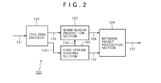
- FIG. 2 shows an example of principal components of the distribution data production apparatus 101 shown in FIG. 1 .
- the distribution data production apparatus 101 includes, a for example, a JPEG 2000 encoder 121, a code stream dividing section 122, a NORM header production section 123, and a network packet production section 124.
- the JPEG 2000 encoder 121 codes the image data by the JPEG 2000 method to generate a code stream.
- the JPEG 2000 encoder 121 supplies the generated code stream to the code stream dividing section 122 as indicated by an arrow mark 132.
- the code stream dividing section 122 divides the code stream supplied thereto for each predetermined data length suitable for placement into a network packet.
- the data length of a code stream of JPEG 2000 is much greater than the data length of an IP packet to be transmitted to a network. Accordingly, it is basically necessary to divide the code stream generated by the JPEG 2000 encoder 121 into a plurality of packets in accordance with an JP packet length.
- the code stream dividing section 122 supplies the divisional code streams obtained by dividing the code stream to the network packet production section 124 as indicated by an arrow mark 133.
- the code stream dividing section 122 further supplies the divisional code streams to the NORM header production section 123 as indicated by an arrow mark 134.
- the JPEG 2000 encoder 121 generates progression order information representative of a data configuration, which is an order of code data wherein an image characteristic amount such as resolution or a layer is used as a variable, regarding the generated code stream. Then, the JPEG 2000 encoder 121 supplies the progression order information to the NORM header production section 123 as indicated by an arrow mark 135.
- the NORM header production section 123 generates a NORM header for each of the divisional code streams supplied thereto from the code stream dividing section 122.
- the NORM header production section 123 further specifies the image characteristic amount such as resolution or a layer of each of the divisional code streams and describes the specified information into the expansion region of the NORM header.
- the NORM header production section 123 supplies the generated NORM header to the network packet production section 124 as indicated by an arrow mark 136).
- the network packet production section 124 generates a header for each of the divisional code streams supplied thereto from the code stream dividing section 122 using a corresponding one of the NORM headers supplied thereto from the NORM header production section 123 to generate a network packet.
- the network packet production section 124 outputs the generated network packet as indicated by an arrow mark 137 and supplies the network packet, for example, to the content server 102 so as to be accumulated into the content server 102.
- FIG. 3 shows an example of principal components of the JPEG 2000 encoder of FIG. 2 .
- the JPEG 2000 encoder 121 carries out wavelet conversion of image data and develops coefficients obtained by the wavelet conversion into a bit plane for each code block and then carries out entropy encoding for each bit plane.
- the JPEG 2000 encoder 121 carries out entropy encoding called EBCOT (Embedded Block Coding with Optimized Truncation) prescribed in the JPEG 2000 specification (refer to ISO/IEC 15444-1, Information technology-JPEG 2000, Part 1: Core coding system).
- EBCOT Embedded Block Coding with Optimized Truncation
- EBCOT Embedded Block Coding with Optimized Truncation
- the JPEG 2000 encoder 121 includes a wavelet conversion unit 151, a quantization unit 152, a code blocking unit 153, a bit plane development unit 154, an EBCOT 155, and a code stream production unit 156.
- the wavelet conversion unit 151 is implemented by a filter bank usually configured from a low-pass filter and a high-pass filter. Further, since a digital filter usually has an impulse response or filter coefficient having a length of a plurality of taps, the wavelet conversion unit 151 has a buffer for buffering input images, with which filtering can be carried out, in advance.
- the wavelet conversion unit 151 acquires an amount of inputted image data indicated by an arrow mark 131 greater than a minimum data amount necessary for filtering.
- the wavelet conversion unit 151 applies filtering to the acquired image data using, for example, a 5 x 3 wavelet conversion filter to generate wavelet coefficients. It is to be noted that the wavelet conversion unit 151 carries out filtering of separating image data into low frequency components and high frequency components for each of the vertical direction and the horizontal direction of an image.
- the wavelet conversion unit 151 repeats such a filtering process as described above recursively by a predetermined number of times for sub bands separated as the low frequency components in both of the vertical direction and the horizontal direction. This is because much energy of an image is concentrated on low frequency components as seen in FIG. 4 .
- FIG. 4 illustrates an example of a configuration of sub bands. As seen in FIG. 4 , not only in a state of the division level number 1 but also in a state of the division level number 3, most of energy of an image is concentrated on low frequency components.
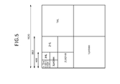
- FIG. 5 illustrates an example of a configuration of sub bands generated by a wavelet conversion process of the division level number 4.
- the wavelet conversion unit 151 first carries out filtering of an entire image to produce sub bands 1LL (not shown), 1HL, 1LH and 1HH. Then, the wavelet conversion unit 151 carries out filtering again of the generated sub band 1LL to produce sub bands 2LL (not shown), 2HL, 2LH and 2HH. Further, the wavelet conversion unit 151 carries out filtering again of the generated sub band 2LL to produce sub bands 3LL, 3HL, 3LH and 3HH. Further, the wavelet conversion unit 151 carries out filtering again of the generates sub band 3LL to produce sub bands 4LL, 4HL, 4LH and 4HH.
- division level number of wavelet conversion can be selected arbitrarily.
- the wavelet conversion unit 151 supplies the coefficient data, that is, wavelet coefficients, obtained by the filtering to the quantization unit 152 for each sub band as indicated by an arrow mark 172.
- the quantization unit 152 quantizes coefficient data, that is, a wavelet coefficient, supplied thereto.
- the quantization unit 152 supplies coefficient data, that is, a quantization coefficient, obtained by the quantization to the code blocking unit 153 as indicated by an arrow mark 173.
- the quantization process is omitted in reversible compression.
- the coefficient data, that is, a wavelet coefficient, outputted from the wavelet conversion unit 151 is supplied to the code blocking unit 153 as indicated by an arrow mark 174.
- the quantization unit 152 can be omitted.
- the code blocking unit 153 divides coefficient data, that is, quantized coefficient data, supplied thereto into code blocks of a rectangular shape of a predetermined size which are individually processing units of entropy coding.
- coefficient data that is, quantized coefficient data
- the code blocking unit 153 divides coefficient data, that is, quantized coefficient data, supplied thereto into code blocks of a rectangular shape of a predetermined size which are individually processing units of entropy coding.
- the vertical and horizontal sizes of the code block are equal among all sub bands.
- FIG. 6 illustrates an example of a positional relationship of code blocks in sub bands.
- the division level number is 3.
- a code block of a size of approximately 64 x 64 pixels is produced in all sub bands after division.
- the size of the sub band of the code block 1HH where the division level is lowest is 640 x 320 pixels, then totaling 50 code blocks of 64 x 64 pixels exist.
- processing is carried out for each of the code blocks.
- the size, that is, the pixel number, of the code blocks can be selected arbitrarily.
- the code blocking unit 153 supplies the coefficient data for the individual code blocks to the bit plane development unit 154 as indicated by an arrow mark 175.
- the bit plane development unit 154 develops the coefficient data for the individual code blocks supplied thereto into bit planes for the individual significances of the bits.
- a bit plane is formed by dividing or slicing a coefficient group including a predetermined number of wavelet coefficients such as code blocks hereinafter described for each one bit, that is, for each significance.
- a bit plane is a set of bits, that is, of coefficient bits, at the same significance of a plurality of data having bit depths of a plurality of bits. Accordingly, a bit plane to be developed relies upon the bit depth of each coefficient.
- FIG. 7 A particular example is illustrated in FIG. 7 .
- a left side view of FIG. 7 shows totaling 16 coefficients including four coefficients in the vertical direction and four coefficients in the horizontal direction. Of the 16 coefficients, the coefficient 13 has a maximum absolute value and is represented as 1101 in binary number.
- the bit plane development unit 154 develops such a coefficient group as just described into four bit planes representative of absolute values, that is, four bit planes of absolute values, and one bit plane representative of codes, that is, a bit plane of codes.
- the coefficient group shown in a left portion of FIG. 7 is developed into four bit plates of absolute values and one bit plane of codes as shown in a right portion of FIG. 7 .
- the elements of the bit planes of absolute values all assume one of the values of 0 and 1.
- the elements of the bit plane which indicate codes all assume one of a value representing that the value of the coefficient is in the positive, another value representing that the value of coefficients is 0 and a further value representing that the value of coefficients is in the negative
- bit plane development unit 154 develops coefficients into a bit plane for each code block.
- the bit plane development unit 154 supplies bit planes developed in this manner to the EBCOT 155 in an order from the most significant bit (MSB) to the least significant bit (LSB) of the coefficients.
- the bit plane development unit 154 supplies the developed bit planes to the EBCOT 155 in the order from the higher order side toward the lower order side of the bit depth as indicated by an arrow mark 176.
- the EBCOT 155 carries out coding for each block of a predetermined size while measuring a statistic of the coefficients in the block.
- the EBCOT 155 entropy codes coefficient data, that is, quantization coefficients, in a unit of a code block.
- the individual code blocks are coded in a direction from the most significant bit (MSB) toward the least significant bit (LSB) independently for each bit plane.
- MSB most significant bit
- LSB least significant bit
- Each of the vertical and horizontal sizes of the code blocks is a power of 2 ranging from 4 to 256, and those sizes which are used normally are 32 x 32, 64 x 64, 128 x 32 and so forth.
- a quantization coefficient value is represented by a binary number with a sign of n bits and bit 0 to bit n-1 individually represent bits from the LSB to the MSB. The remaining one bit is a sign. Coding of a code block is carried out by the following three coding passes in order from the bit plane on the MSB side:
- FIG. 8 The order in which the three coding passes are used is illustrated in FIG. 8 .
- the Bitplane (n-1) (MSB) is coded by the Cleanup Pass.
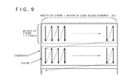
- a code block is divided into stripes for each four coefficients of the height.
- the width of each stripe is equal to the width of the code block.
- the scanning order is an order of traversing all coefficients in one code block, and within the code block, the stripes are scanned in order from the uppermost stripe toward the lowermost stripe. Further, in each stripe, the columns are scanned in order from the leftmost column toward the rightmost column, and in each column, the coefficients are scanned in order from the uppermost coefficient toward the lowermost coefficient. In the coding passes, all coefficients in the code block are processed in this scanning order.
- the value of a bit plane of a non-significant coefficient around which at least one of eight neighboring coefficients is significant is arithmetically coded.
- the coded value of the bit train is 1, whether the sign is + or - is MQ coded subsequently.
- the significance represents a state which a coder has for each coefficient, and the initial value of the significance is 0 which represents non-significant. Then, when 1 is coded with the coefficient in this state, the significance changes to 1 which represents significant, and thereafter, the significance continues to be 1. Accordingly, it is considered that the significance is a flag representing whether or not information of an effective figure has already been coded. If the significance changes to significant on a certain bit plane, then it remains significant on all succeeding bit planes.
- the value of a bit plane of significant coefficients which are significant in the Significance Propagation Pass which codes the bit plane and are not coded is MQ coded.
- the value of a bit plane of non-significant coefficients which are non-significant in the Significance Propagation Pass which codes the bit plane and which are not coded is MQ coded.
- the coded value of the bit plane is 1, whether the sign is + or -, that is, Sign information, is MQ coded subsequently
- MQ coding is binary arithmetic coding of the learning type prescribed in JBIG2 (reference document: ISO/ICE FDIS 14492, "Lossy/Lossless Coding of Bi-level Images,” March 2000).
- the EBCOT 155 includes a bit modeling device 161 configured to carry out bit modeling, and an MQ coding device 162 configured to carry out arithmetic coding.
- the bit modeling device 161 After the bit modeling device 161 carries out bit modeling, it supplies control information, symbols and information of the context and so forth to the MQ coding device 162 as indicated by an arrow mark 177.
- the MQ coding device 162 carries out MQ coding using a data group supplied thereto.
- the MQ coding device 162 supplies coded data produced by the MQ coding to the code stream production unit 156 as indicated by an arrow mark 178.
- the code stream production unit 156 aligns coded data supplied thereto from the EBCOT 155, particularly from the MQ coding device 162, and outputs the aligned data as a single code stream as indicated by an arrow mark 179. More particularly, the code stream production unit 156 re-arranges the coded data to produce a code stream formed from a packet group of a structure with which the Resolution and the Layer are scalable, which is a characteristic of JPEG 2000. As described hereinabove with reference to FIG. 2 , the code stream outputted from the code stream production unit 156 is supplied to the code stream dividing section 122.
- code stream production unit 156 further supplies progression order information representative of a structure of the produced code stream to the NORM header production section 123 as indicated by an arrow mark 180.
- NORM header production section 123 shown in FIG. 2 is described.
- a code stream produced by the JPEG 2000 encoder 121 is divided by the code stream dividing section 122 and supplied as a plurality of divisional code streams to the NORM header production section 123.
- progression order information is supplied from the JPEG 2000 encoder 121.
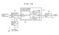
- FIG. 10 shows an example of principal components of the NORM header production section 123 shown in FIG. 2 .
- the NORM header production section 123 includes an address extraction unit 191, a resolution and layer calculation unit 192, an attribute number calculation unit 193 and a header describing unit 194.
- the address extraction unit 191 extracts an address of the start, that is, a start address, and an address of the end, that is, an end address, of each of divisional code streams supplied thereto from the code stream dividing section 122 as indicated by an arrow mark 134.
- the address extraction unit 191 supplies the extracted start addresses and end addresses of the divisional code streams to the resolution and layer calculation unit 192 as indicated by an arrow mark 211.
- the resolution and layer calculation unit 192 calculates, based on the structure of the code stream indicated by the progression order information supplied from the JPEG 2000 encoder 121, resolution and a layer which are image characteristic amounts, which become variables regarding the progression, for each of the start addresses and the end addresses supplied from the address extraction unit 191.
- the layer is described. As described hereinabove, image data are developed into a bit plane and coded for each code block. In other words, the coding passes in each code block are arranged in the order of bit planes.
- the layer is obtained by dividing data coded for each code block in this manner for each one bit plane or for each plural bit planes. Therefore, each layer is formed from one or a plurality of bit planes. In other words, data coded for each code block are developed over one or a plurality of layers in a code stream.
- the coding pass number in a layer can be set for each block. Also it is possible to set the coding pass number to 0.
- the picture quality of image data is enhanced as the layer number increases.
- the picture quality of image data can be adjusted by decreasing or increasing the number of divisional layers.
- one picture is divided into N layers from layer 1 to layer N, and one layer is configured from four packets. This packet number per one layer is defined by "wavelet decomposition level number + 1.”
- a code stream is scalably coded with regard to the layer, that is, the picture quality. Further, as described hereinabove with reference FIG. 5 , image data are divided into a plurality of sub bands and coded for each of the sub bands. Accordingly, a code stream is scalably coded also with regard to the resolution. In other words, in a code stream coded in accordance with the JPEG 2000 method, coded data are packed for each predetermined unit and arranged such that they are scalable with regard to the resolution and the layer.
- a row of such coded data or packets as described above is called progression.
- coded data are arranged in regard to the resolution and the layer. Accordingly, the resolution and the layer, which are image characteristic amounts, in this instance are called variables regarding the progression.
- the first arrangement method is a method which arranges coded data of layers for each resolution.
- the type of a code stream for which such an arrangement method as just described is adopted is referred to as L-R type (Layer-Resolution Type).
- FIG. 12 illustrates an example of a configuration of a code stream of the L-R type.
- the code stream 231 includes an SOC (Start of Codestream), a Main header and a Tile-part header arranged in this order and followed by coded data of the individual layers arranged in order of the resolution.
- SOC Start of Codestream
- Main header a Main header
- Tile-part header arranged in this order and followed by coded data of the individual layers arranged in order of the resolution.
- L and R in FIG. 12 are arbitrary natural numbers.
- the L-R type includes the Layer in the first high hierarchical layer and the Resolution in the succeeding layer. Accordingly, if this code stream is decoded in order beginning with the start thereof, then such an image as shown in FIG. 13 can be restored.
- the Layer-1 includes packets of all resolutions from the Resolution number 1 to the Resolution number R, and by decoding this Layer-1, the first layer of an image of resolution same as that of the original image can be restored. Similarly, if the Layer-2 is decoded and a resulting image is adjusted to the decoded image of the Layer-1, then the picture quality is improved. By repetitively executing this up to the last layer-L, a final decoded image is outputted.
- picture quality indicates various events, an event which relies upon a layer to be restored is hereinafter referred to as "picture quality.”
- the “resolution” and the “picture quality” of an image are characteristic amounts of the image.
- the “resolution” and the “layer” in a code stream are variables corresponding to the characteristic amounts. Accordingly, in the following description, the "resolution” and the “layer” in a code stream are regarded as equivalent to the “resolution” and the “picture quality” of an image and are sometimes referred to as "characteristic amounts of the (an) image.”
- the second arrangement method is a method of arranging coded data of resolutions for each layer.
- the type of a code stream for which such an arrangement method as just described is adopted is referred to as R-L type (Resolution-Layer Type).
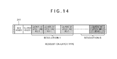
- FIG. 14 illustrates an example of a configuration of a code stream of the R-L type.
- the code stream 241 includes an SOC (Start of Codestream), a Main header and a Tile-part header arranged in this order and followed by coded data of the resolutions arranged in order of the layer.
- SOC Start of Codestream
- Main header a Main header
- Tile-part header arranged in this order and followed by coded data of the resolutions arranged in order of the layer.
- L and R in FIG. 14 are arbitrary natural numbers.
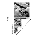
- the R-L type includes the Resolution in the first high hierarchical layer and the Layer in the succeeding layer. Accordingly, if this code stream is decoded in order beginning with the start thereof, then such an image as shown in FIG. 15 can be restored.
- the Res-1 includes packets of all layers from the Layer number 1 to the Layer number L, and by decoding this Res-1, the lowest resolution of an image of the highest picture quality can be restored. Similarly, by decoding the Res-2 and adjusting a resulting image to the decoded image of the Res-1, the resolution is improved to twice in both of the horizontal and vertical directions. By repetitively executing this up to the last Res-R, a final decoded image is outputted.
- the resolution and layer calculation unit 192 specifies the type of a code stream from progression order information. Since the resolution and the structure of layers of the code stream can be found from the specified type, the resolution and layer calculation unit 192 can determine the resolution and the layer corresponding to each of the start and end addresses.
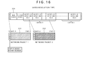
- FIG. 16 illustrates an example of a manner of production of a network packet of the L-R type.
- the code stream 231 of the L-R type is divided by the code stream dividing section 122 to produce a divisional code stream 251 and another divisional code stream 252.
- the divisional code stream 251 makes the Body, that is, the body data part, of a first network packet, that is, the Network Packet 1.
- the divisional code stream 252 makes the Body, that is, the body data part, of a second network packet, that is, the Network Packet 2.
- the address extraction unit 191 of the NORM header production section 123 determines the start address Start-1 and the end address End-1 of the divisional code stream 251. Further, the address extraction unit 191 determines the start address Start-2 and the end address End-2 of the divisional code stream 252.
- the start address Start-1 of the divisional code stream 251 is equal to the start address of the SOC marker of the original code stream 231
- the end address End-1 of the divisional code stream 251 is equal to an intermediate address of the packet of the layer 1 and the resolution 1, that is, Layer-1 and Res-1.
- start address Start-2 of the divisional code stream 252 is equal to the address immediately following the end address End-1 of the divisional code stream 251, and the end address End-2 of the divisional code stream 252 is equal to an intermediate address of the packet of the layer 1 and the resolution R, that is, Layer-1 and Res-R.
- the progression order information represents such a structure of a code beam as illustrated on the top stage of FIG. 16 , that is, from what header and packets the code stream from a specified address to another specified address is formed.
- the resolution and layer calculation unit 192 confirms from the progression order information that the code stream is of the L-R type, then it determines, based on the structure, the layer number and the resolution number corresponding to the start address and the end address of each of divisional code streams as described hereinabove.
- the resolution and layer calculation unit 192 defines
- the header HDR of each of the network packets illustrated in FIG. 16 is a combination of a UDP header and a NORM header. Since the UDP is different from the TCP in that it does not involve transmission confirmation and so forth, the data ratio is higher. Accordingly, the UDP is used frequently for streaming of images and so forth with which it does not become a significant problem even if some data are lost intermediately.
- the resolution and layer calculation unit 192 calculates the values of the variables (R_f, R_t) and (L_f, L_t) described hereinabove, it supplies the values to the attribute number calculation unit 193 as indicated by an arrow mark 212.
- the attribute number calculation unit 193 uses the values of the variables (R_f, R_t) and (L_f, L_t) to calculate, for each of the start and the end of each divisional code stream or each network packet, an attribute number which is an identification number for the identification of the image characteristic amounts, that is, the resolution and the layer.
- the attribute number calculation unit 193 includes a type discrimination device 201, an L-R calculation device 202 and an R-L calculation device 203.
- the type discrimination device 201 discriminates the type of the code stream based on the progression order information supplied thereto from the resolution and layer calculation unit 192. If the type of the code stream is the L-R type, then the type discrimination device 201 supplies the values of the variables (R_f, R_t) and (L_f, L_t) of each divisional code stream supplied thereto from the resolution and layer calculation unit 192 to the L-R calculation device 202 as indicated by an arrow mark 221.
- the Layer-number indicates the layer number
- the Resolution level number indicates a maximum value of the resolution number, that is, the divisional level number of wavelet conversion while the Resolution-number indicates the resolution number.
- the L-R calculation device 202 determines the start value and the end value of the attribute number with regard to all divisional code streams whose variables (R_f, R_t) and (L_f, L_t) are supplied thereto as described above.
- the L-R calculation device 202 supplies the determined start values and end values of the attribute numbers to the header describing unit 194 as indicated by an arrow mark 213.
- the header describing unit 194 produces a NORM header for each of the divisional code streams of the start values and the end values of the attribute numbers supplied thereto from the L-R calculation device 202 and describes the start value and the end value of the attribute number into the extended parameter region of the NORM header.
- FIG. 17 illustrates an example of a configuration of the NORM header.
- the header describing unit 194 produces a NORM header 261 of such a configuration as seen in FIG. 17 and describes the values of X, Attribute type, FROM, TO ad so forth into the extended parameter region, that is, into the reserved region.
- X represents an attribute extension flag indicative of whether or not an attribute number is described in the NORM header 261.
- the attribute extension flag may have an arbitrary data length, the data length thereof may be, for example, 1 bit.
- the attribute extension flag may have an arbitrary value, for example, the value of the attribute extension flag X where a value of an attribute number is described in the NORM header 261 may be "1" while the value of the attribute extension flag X where a value of an attribute number is not described in the NORM header 261 may be "0.”
- the Attribute type indicates a type of a code stream described hereinabove. While the attribute type may have an arbitrary data length, the data length thereof may be, for example, 8 bits. Further, although the attribute type may have an arbitrary value, for example, the value of the attribute type where the code stream is of the L-R type may be "0" while the value of the attribute type where the code stream is of the R-L type may be "1.” Further, where a type different from the L-R type and the R-L type is available, it is possible to apply a different value.
- the FROM indicates the start value of the attribute number.
- the TO indicates the end value of the attribute number.
- the values may have any data length, the data length thereof may be, for example, 8 bits.
- the header describing unit 194 produces a NORM header, sets the attribute extension flag X to the value "1" and sets the value of the attribute type to "0.” Further, the header describing unit 194 describes the start value of the attribute number supplied thereto from the L-R calculation device 202 into the FROM and describes the end value of the attribute number supplied thereto from the L-R calculation device 202 into the TO.
- the header describing unit 194 supplies the produced NORM header to the network packet production section 124 as indicated by an arrow mark 136.
- processing is carried out in such a manner as described above.
- FIG. 18 illustrates an example of a manner of production of a network packet of the R-L type.
- code stream dividing section 122 divides a code stream 241 of the R-L type to produce a divisional code stream 271 and another divisional code stream 272.
- the divisional code stream 271 makes the Body, which is a body data part, of a first network packet, that is, Network Packet 1.
- the divisional code stream 272 makes the Body, which is a body data part, of a second network packet, that is, Network Packet 2.
- the address extraction unit 191 of the NORM header production section 123 determines the top address Start-1 and the end address End-1 of the divisional code stream 271. Further, the address extraction unit 191 determines the start address Start-2 and the end address End-2 of the divisional code stream 272.
- the start address Start-1 of the divisional code stream 271 is equal to the start address of the SOC marker of the original code stream 241
- the end address End-1 of the divisional code stream 271 is equal to an intermediate address of the packet of the layer 1 and the resolution 1, that is, Layer-1 and Res-1.
- start address Start-2 of the divisional code stream 272 is equal to the address immediately following the end address End-1 of the divisional code stream 271, and the end address End-2 of the divisional code stream 272 is equal to an intermediate address of the packet of the layer L and the resolution 1, that is, Layer-L and Res-1.
- the resolution and layer calculation unit 192 confirms from the progression order information that the code stream is of the R-L type, then it determines, based on the structure, the values of the variables (R_f, R_t) and (L_f, L_t) regarding of each of the divisional code streams as described hereinabove.
- the resolution and layer calculation unit 192 calculates the values of the variables (R_f, R_t) and (L_f, L_t) described hereinabove, it supplies the values to the attribute number calculation unit 193 as indicated by an arrow mark 212.
- the attribute number calculation unit 193 calculates an attribute number for each of the start and the end of each divisional code stream or each network packet.
- the type discrimination device 201 supplies, where the type of the code stream is the R-L type, the values of the variables (R_f, R_t) and (L_f, L_t) supplied thereto from the resolution and layer calculation unit 192 to the R-L calculation device 203 as indicated by an arrow mark 222.
- the total layer number is the total number of layers.
- the R-L calculation device 203 determines the start value and the end value of the attribute number with regard to all divisional code streams the values of the variables (R_f, R_t) and (L_f, L_t) of which are supplied thereto as described above.
- the R-L calculation device 203 supplies the determined start values and end values of the attribute numbers to the header describing unit 194 as indicated by an arrow mark 213.
- the header describing unit 194 produces a NORM header for each of the divisional code streams of the start values and the end values of the attribute numbers supplied thereto from the R-L calculation device 203 and describes the start value and the end value of the attribute number into the extended parameter region of the NORM header.
- This method is basically same as that in the case of the L-R type described hereinabove. For example, if the start value and the end value of the attribute number are supplied from the R-L calculation device 203, then the header describing unit 194 produces a NORM header, sets the attribute extension flag X to the value "1" and sets the value of the attribute type to "1.” Further, the header describing unit 194 describes the start value of the attribute number supplied thereto from the R-L calculation device 203 into the FROM and describes the end value of the attribute number supplied thereto from the R-L calculation device 203 into the TO.
- the header describing unit 194 supplies the produced NORM header to the network packet production section 124 as indicated by an arrow mark 136.
- the distribution data production apparatus 101 starts the distribution data production process to produce data for distribution from the image data or content data.
- the JPEG 2000 encoder 121 codes the image data for production of distribution data using the JPEG 2000 method at step S101.
- the code stream dividing section 122 divides the code stream obtained by the coding for each of predetermined data lengths to produce divisional code streams.
- the NORM header production section 123 produces an NORM header for each of the divisional code streams and describes a start value and an end value of an attribute number into the extended parameter region.
- the network packet production section 124 converts each divisional code stream into a packet using the produced NORM header to produce a network packet.
- the network packet production section 124 outputs the produced network packets.
- the network packets outputted from the distribution data production apparatus 101 are supplied to and stored into the content server 102.
- the wavelet conversion unit 151 carries out wavelet conversion of image data by one picture at step S121.
- the quantization unit 152 quantizes the coefficient data produced at step S121. It is to be noted that, in the case of reversible coding, the processing at step S122 is omitted.
- the code blocking unit 153 carries out code blocking of the coefficient data.
- the bit plane development unit 154 carries out bit plane development of the coefficient data of each code block.
- bit modeling device 161 of the EBCOT 155 executes a bit modeling process.
- the MQ coding device 162 of the EBCOT 155 carries out an MQ coding process.
- the code stream production unit 156 aligns the produced encoded data in the EBCOT 155 to produce a code stream. Further, at step S128, the code stream production unit 156 produces progression order information regarding the produced code stream.
- the code stream production unit 156 outputs the code stream. Further, at step S130, the code stream production unit 156 outputs the progression order information.
- step S130 If the processing at step S130 is ended, then the coding process is ended, and the processing returns to step S101 in FIG. 19 and then the processes after step S102 are executed.
- the address extraction unit 191 extracts, at step S151, a start address and an end address of each of the divisional code streams.
- the resolution and layer calculation unit 192 calculates resolution and layers, which are image characteristic amounts, at the start and the end of each divisional code stream from the start address and the end address based on the progression order information.
- the attribute number calculation unit 193 calculates a start value and an end value of the attribute number of each divisional code stream from the resolution and the layers at the start and the end of the divisional code streams.
- the header description section 194 produces a NORM header regarding each of the divisional code streams and describes the start value and the end value of the attribute number into the produced NORM header.
- step S154 If the processing at step S154 is ended, then the processing returns to step S103 in FIG. 19 to execute the processes at and the processes at the steps beginning with step S104.
- the type discrimination device 201 discriminates the type of the code stream from the progression order information.
- the type discrimination device 201 advances the processing from step S172 to step S173.
- the L-R calculation device 202 calculates an attribute number from the resolution number and the layer number using an L-R calculation expression such as the expression (1).
- the type discrimination device 201 advances the processing from step S172 to step S174.
- the R-L calculation device 203 calculates an attribute number from the resolution number and the layer number using an R-L calculation expression such as the expression (2).
- step S154 After the attribute number is calculated, the attribute number calculation process is ended, and the processing returns to step S153 in FIG. 21 to execute processes at the steps beginning with step S154.
- the NORM header production section 123 describes, regarding each of the start and the end of a network packet, that is, a divisional code stream, the attribute number and so forth as information indicative of resolution of a layer, that is, image characteristic amounts, into the extended parameter region of the NORM header.
- the distribution server 103 which processes or distributes network packets can readily acquire necessary data in response to desired image characteristic amounts only by carrying out suitable selection based on the information of the NORM header.
- the distribution data production apparatus 101 adds information regarding the attribute number, for example, information regarding image characteristic amounts such as resolution, a layer and so forth to a network packet. Consequently, the distribution data production apparatus 101 can produce a network packet from which the distribution server 103 can easily acquire necessary data in response to a desired image characteristic amount such as resolution or picture quality.
- the information regarding the attribute number may be added to or described at an arbitrary position other than the extended parameter region described hereinabove or at a position other than the NORM header.
- the resolution and layer calculation unit 192 grasps the structure of a code stream based on the progression order information, it can determine a resolution number and a layer number correctly irrespective of the type of the code stream.
- the attribute number calculation unit 193 discriminates the type of the code stream and determines the attribute number using a calculation expression suitable for the type, it can determine the attribute number correctly irrespective of the type of the code stream.
- the distribution server 103 which processes or distributes a network packet can grasp the type of the code stream readily based on the information of the NORM header. In other words, the distribution server 103 can carry out appropriate processing readily irrespective of the type of the code stream.
- the NORM header production section 123 describes an attribute number into the NORM header
- image characteristic amounts such as a resolution number and a layer number may be described in place of the attribute number.
- the attribute number is a single value and exhibits a data amount smaller than a resolution number and a layer number.
- the data amount of a network packet can be reduced in comparison with an alternative case in which both of the resolution number and the layer number are described.
- a type other than the L-R type and the R-L type described hereinabove may be provided.
- an image characteristic amount other than the resolution and the layer may be applied.
- the number of types to be applied is selected arbitrarily and may be three or more or otherwise may be one.
- the resolution and layer calculation unit 192 can grasp the structure of code streams of all types to be applied by referring to the progression order information. It is to be noted that, where an image characteristic amount other than the resolution and the layer is applied as a variable regarding the progression, the resolution and layer calculation unit 192 determines an identification number of the image characteristic mount similarly as in the case of the resolution number or the layer number.
- the attribute number calculation unit 193 includes calculation devices configured to calculate, regarding all types to be applied, an attribute number using calculation expressions for exclusive use for the individual types.
- the type discrimination device 201 supplies information of the resolution number, layer number and so forth of each divisional code stream to the calculation device corresponding to the discriminated type.
- the distribution server 103 acquires a network packet from the content server 102 and distributes the network packet to the terminal apparatus 104 and/or the terminal apparatus 105.
- the distribution server 103 selects only network packets of necessary data in response to a desired image characteristic amount based on the attribute number included in the NORM header of each network packet.
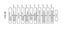
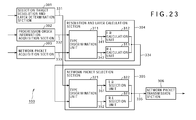
- FIG. 23 shows an example of principal components of the distribution server 103 shown in FIG. 1 .
- the distribution server 103 shown includes a selection target resolution and layer determination section 301, a progression order information acquisition section 302, a network packet acquisition section 303, a resolution and layer calculation section 304, a network packet selection section 305 and a network packet transmission section 306.
- the selection target resolution and layer determination section 301 determines resolution and a layer of an image to be distributed, that is, of a target of selection, that is, determines image characteristic amounts, based on various kinds of information.
- an image to be distributed by the selection target resolution and layer determination section 301 has resolution or picture quality unnecessarily high with respect to a performance or a situation of the terminal apparatus 104 which is a distribution destination, then there is the possibility that some fault may occur in data transmission or image display.
- an image to be distributed by the selection target resolution and layer determination section 301 has resolution or picture quality unnecessarily low with respect to a performance of the terminal apparatus 104 of a distribution object, then image display which makes the best use of a performance of the terminal apparatus can not be implemented. In other words, only it is possible to display an image of an unnecessarily low resolution and unnecessarily low picture quality.
- the data transmission amount is not preferable in both of a case in which it is excessively great and another case in which it is excessively small with respect to the bandwidth which can be used by a network to be used as a transmission line for a network packet. Further, it is preferable for the data transmission amount to be appropriate with respect to the capacity or the situation of the distribution server 103 itself. Furthermore, where a billing process is to be carried out for distribution of a content, the resolution or the picture quality or layer of an image to be distributed may be controlled in response to the amount of payment for the charge by a terminal apparatus from which a request for distribution is issued.
- the selection target resolution and layer determination section 301 determines resolution and a layer, which are image characteristic amounts, of a target of selection based on arbitrary conditions, for example, the performance or the state of an apparatus of the distribution destination such as the reception processing capacity, image processing capacity, buffer capacity or resolution of the monitor, a usable bandwidth of a network to be used as a transmission line for a network packet, the performance or the state of the distribution server 103 itself, the amount of payment of the charge for the distribution or an instruction of the user.
- the performance or the state of an apparatus of the distribution destination such as the reception processing capacity, image processing capacity, buffer capacity or resolution of the monitor, a usable bandwidth of a network to be used as a transmission line for a network packet, the performance or the state of the distribution server 103 itself, the amount of payment of the charge for the distribution or an instruction of the user.
- the selection target resolution and layer determination section 301 notifies the network packet selection section 305 of information of the determined resolution and layer as indicated by an arrow mark.
- the progression order information acquisition section 302 acquires the progression order information of the code stream corresponding to a network packet to be acquired from the content server 102.
- the progression order information acquisition section 302 supplies the acquired progression order information to the resolution and layer calculation section 304 as indicated by an arrow mark 332.
- the network packet acquisition section 303 acquires a network packet of the content to be distributed from the content server 102 and supplies the content network packet to the resolution and layer calculation section 304 as indicated by an arrow mark 333.
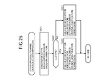
- the resolution and layer calculation section 304 refers to the NORM header of each network packet supplied thereto from the network packet acquisition section 303 and determines a resolution number and a layer number, which are image characteristic amounts, at a start and an end of each network packet from the start value and the end value of the attribute number.
- the resolution and layer calculation section 304 includes a type discrimination unit 311, an L-R calculation unit 312 and an R-L calculation unit 313.
- the type discrimination unit 311 discriminates the type of the code stream corresponding to the network packet supplied from the network packet acquisition section 303 as indicated by an arrow mark 333 based on the progression order information supplied from the progression order information acquisition section 302 as indicated by an arrow mark 332.
- the type discrimination unit 311 supplies the network packet supplied thereto from the network packet acquisition section 303 to the L-R calculation unit 312 as indicated by an arrow mark 341.
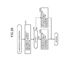
- the L-R calculation unit 312 uses such a calculation expression for the L-R as given hereinabove as the expression (1) to determine, for each divisional code stream, the start value and end value (R_f, R_t) of the resolution number and the start value and end value (L_f, L_t) of the layer number from the start value and the end value of the attribute number.
- R_f and R_t or L_f and L_t are determined from one value, they are all natural numbers and besides the resolution numbers R_f and R_t are smaller than the Resolution level number R, that is, Res-R. Accordingly, the start value and end value (R_f, R_t) of the resolution number and the start value and end value (L_f, L_t) of the layer number are decided uniquely from the start value and the end value of the attribute number.
- the L-R calculation unit 312 divides a value obtained by subtracting 1 from the value of the attribute number by the resolution level number R, that is, by Res-R, and sets the quotient as a layer number L_t and sets the remainder as a resolution number R_t. It is to be noted, however, that the remainder must have any other value than zero. In other words, in this instance, the L-R calculation unit 312 sets a value obtained by subtracting 1 from the quotient as the layer number L_t and sets the remainder in this instance as the resolution numberR_t. Thus, the value of the resolution number R_t in this instance is R.
- both of the resolution number R_f and the layer number L_f of the first network packet, that is, of the Network Packet 1, are zero.
- the resolution number R_f and the layer number L_f at the start can be determined similarly as in the case of the resolution number R_t and the layer number L_t of the end described above.
- the L-R calculation unit 312 supplies the start value and the end value (R_f, R_t) of the resolution number and the start value and the end value (L_f, L_t) of the layer number calculated as described above to the network packet selection section 305 together with the network packet as indicated by an arrow mark 334.
- the type discrimination unit 311 supplies network packets supplied thereto from the network packet acquisition section 303 to the R-L calculation unit 313 as indicated by an arrow mark 342.
- the R-L calculation unit 313 uses such a calculation expression for the R-L as given hereinabove as the expression (2) to determine, for each divisional code stream, the start value and end value (R_f, R_t) of the resolution number and the start value and end value (L_f, L_t) of the layer number from the start value and the end value of the attribute number.
- the start value and end value (R_f, R_t) of the resolution number and the start value and end value (L_f, L_t) of the layer number are decided uniquely from the start value and the end value of the attribute number similarly as in the case of the L-R type.
- the R-L calculation unit 313 divides a value obtained by subtracting 1 from the value of the attribute number by the total Layer number L, and sets the quotient as a resolution number R_t and sets the remainder as a layer number L_t. It is to be noted, however, that the remainder must have any other value than zero. In other words, in this instance, the R-L calculation unit 313 sets a value obtained by subtracting 1 from the quotient as the resolution number R_t and sets the remainder in this instance as the layer number L_t. Thus, the value of the layer number L_t in this instance is L.
- both of the resolution number R_f and the layer number L_f of the first network packet, that is, of the Network Packet 1, are zero.
- the resolution number R_f and the layer number L_f at the start can be determined similarly as in the case of the resolution number R_t and the layer number L_t at the end described above.
- the R-L calculation unit 313 supplies the start value and the end value (R_f, R_t) of the resolution number and the start value and the end value (L_f, L_t) of the layer number calculated as described above to the network packet selection section 305 together with the network packet as indicated by an arrow mark 334.
- the network packet selection section 305 carries out selection of network packets based on the designation of the resolutions and the layers, which are image characteristic amounts, supplied thereto from the selection target resolution and layer determination section 301 to select those network packets which are necessary to obtain an image of the designated resolution and layer.
- the network packet selection section 305 selects all of those network packets which include such coded data or packets as just described. In other words, the network packet selection section 305 selects those network packets which include image data in the form of coded data corresponding to images of the resolution and the layer designated by the selection target resolution and layer determination section 301.
- coded data of a code stream are packetized for each of resolutions and layers of images and lined up in a predetermined order. Accordingly, the network packet selection section 305 may select network packets whose Body is a divisional code stream including packets of resolution and a layer corresponding to the designation by the selection target resolution and layer determination section 301.
- Whether or not a network packet includes a packet of a pertaining resolution and a pertaining layer can be determined from the resolution number and the layer number at the start and the end of the divisional code stream.
- the structure of a code stream that is, the line of packets, differs depending upon the type as described hereinabove with reference to FIGS. 16 and 18 .
- the network packet selection section 305 carries out selection of a network packet using a discriminant corresponding to the type of the code stream.
- the network packet selection section 305 includes a type discrimination unit 321, an L-R selection unit 322 and an R-L selection unit 323.
- the type discrimination unit 321 discriminates the type of the code stream corresponding to the network packet based on the progression order information.
- the network packets supplied from the resolution and layer calculation section 304 are supplied to the L-R selection unit 322 as indicated by an arrow mark 351.
- the L-R selection unit 322 uses a discriminant for the R-L prepared for the L-R type to carry out selection of network packets.
- This L-R discriminant corresponds to the structure of the L-R type.
- the L-R selection unit 322 can use this L-R discriminant to correctly specify, from the resolution number and the layer number at the start and the end of the network packet produced from the code stream of the L-R type, whether or not the network packet includes coded data or a packet necessary to obtain an image of the resolution and the layer determined by the selection target resolution and layer determination section 301.
- the L-R selection unit 322 selects those network packets which satisfy the condition in this manner, and supplies the extracted network packets to the network packet transmission section 306 as indicated by an arrow mark 335.
- the type discrimination unit 321 supplies the network packets supplied from the resolution and layer calculation section 304 to the R-L selection unit 323 as indicated by an arrow mark 352.
- the R-L selection unit 323 uses a discriminant for the R-L prepared for the R-L type to carry out selection of network packets.
- This R-L discriminant corresponds to the structure of the R-L type.
- the R-L selection unit 323 can use this R-L discriminant to correctly specify, from the resolution number and the layer number at the start and the end of the network packet produced from the code stream of the R-L type, whether or not the network packet includes coded data or a packet necessary to obtain an image of the resolution and the layer determined by the selection target resolution and layer determination section 301.
- the R-L selection unit 323 selects those network packets which satisfy the condition in this manner, and supplies the extracted network packets to the network packet transmission section 306 as indicated by an arrow mark 335.
- the network packet transmission section 306 transmits the network packets selected by the network packet selection section 305 to the terminal apparatus 104 or the terminal apparatus 105 which becomes a distribution destination.
- the distribution server 103 starts a network packet distribution process.
- the selection target resolution and layer determination section 301 determines resolution and a layer of a selection target at step S301.
- the progression order information acquisition section 302 acquires progression order information of a desired content from the content server 102.
- the network packet acquisition section 303 acquires a network packet of the desired content from the content server 102.
- the resolution and layer calculation section 304 calculates the resolution and the layer at the start and the end of the divisional code streams.
- the network packet selection section 305 selects the network packet based on the resolution and the layer of the selection target.
- the network packet transmission section 306 transmits the selected network packet.
- the network packet acquisition section 303 discriminates whether or not all network packets are processed. If it is discriminated that a network packet which is not processed as yet exists in the desired content, then the processing returns to step S303 to repeat the processes at the steps beginning with step S303.
- step S307 if it is discriminated at step S307 that the network packets of the desired content are all processed, then the network packet distribution process is ended.
- the type discrimination unit 311 discriminates the type of the code stream based on progression order information at step S321.
- the type discrimination unit 311 advances the processing from step S322 to step S323.
- the L-R calculation unit 312 uses the L-R calculation expression to determine a resolution number and a layer number from the attribute number.
- the type discrimination unit 311 advances the processing from step S322 to step S324.
- the R-L calculation unit 313 uses the R-L calculation expression to determine a resolution number and a layer number from the attribute number.
- step S305 After a resolution number and a layer number are determined, the resolution and layer calculation process is ended, and the processing returns to step S304 of FIG. 24 so that the processes at the steps beginning with step S305 are executed.
- the type discrimination unit 321 discriminates, at step S341, the type of the code stream based on the progression order information.
- the type discrimination unit 321 advances the processing from step S342 to step S343.
- the L-R selection unit 322 uses the L-R discrimination expression to carry out selection of the packet.
- the type discrimination unit 321 advances the processing from step S342 to step S344.
- the R-L selection unit 323 carries out selection of the packet using the R-L discrimination expression.
- step S306 After the packet is selected, the selection process is ended, and the processing returns to step S305 of FIG. 24 to execute the processes at the steps beginning with step S306.
- the resolution and layer calculation section 304 determines, from the start value and the end value of the attribute number described in the extended parameter region of the NORM header of each network packet, the resolution number and the wire number at the start and the end of the divisional code stream included in the network packet.
- the network packet selection section 305 selects and extracts those network packets which are necessary to acquire an image of a desired resolution and a desired layer or desired picture quality based on the resolution number and the layer number.
- the distribution server 103 can acquire necessary data more readily in response to a desired image characteristic amount only by selecting network packets based on information of the attribute number and so forth described in the NORM header.
- the distribution server 103 can process the network packets by a method similar to a conventional method. In other words, the distribution server 103 can easily refer to the information regarding the attribute number to carry out processing.
- the resolution and layer calculation section 304 discriminates the type of the code stream based on the progression order information and uses a calculation expression suitable for the discriminated type to determine a resolution number and a layer number from the attribute number. Therefore, the resolution number and the layer number can be determined correctly irrespective of the type of the code stream.
- the network packet selection section 305 uses a discrimination expression suitable for the type of the code stream to carry out selection of network packets. Therefore, necessary data can be acquired correctly in response to a desired resolution or desired picture quality irrespective of the type of the code stream.
- the distribution server 103 can discriminate the type of the code stream and select a suitable processing method in response to the discriminated type, it can be compatible with a plurality of types.
- the distribution server 103 can be compatible also with a type different from the L-R type and the R-L type described hereinabove.
- an image characteristic amount other than the resolution and the layer may be applied as a variable regarding the progression.
- the number of types to be applied may be selected arbitrarily and may be three or more or may be one.
- the progression order information indicates the structure of the code stream regarding all tapes to be applied. Accordingly, the resolution and layer calculation section 304 and the network packet selection section 305 can refer to the progression order information to grasp the structure of the code stream of all types to be applied.
- the resolution and layer calculation section 304 determines the identification number regarding the characteristic amount similarly as in the case of the resolution number or the layer number.
- the selection target resolution and layer determination section 301 determines a value to be made a selection target regarding the characteristic amount, and the network packet selection section 305 carries out selection of network packets using the value of the characteristic amount as a condition similarly as in the case of the resolution and the layer.
- the resolution and layer calculation section 304 includes calculation units for all of the types to be applied for calculating an image characteristic amount such as a resolution number or a layer number using a calculation expression for each of the types.
- the type discrimination unit 311 supplies information of the attribute number and so forth of each divisional code stream to a calculation unit for the discriminated type.
- the network packet selection section 305 includes selection units for all of the types to be applied for carrying out selection of a network packet using a discriminant for exclusive use for the type.
- the type discrimination unit 321 supplies each network packet to a selection unit for the type discriminated.
- the content distribution system 100 can readily obtain necessary data in response to a desired characteristic amount such as resolution or picture quality.
- the number of component apparatus of the content distribution system 100 can be selected arbitrarily.
- the content server 102 may be omitted while a network packet produced by the distribution data production apparatus 101 is supplied to the distribution server 103.
- the component apparatus may be further connected to an apparatus other than the connection destinations indicated by arrow marks in FIG. 1 .
- the distribution data production apparatus 101 may be connected not only to the content server 102 but also to the distribution server 103, terminal apparatus 104 and terminal apparatus 105.
- the utilization method may be selected arbitrarily.
- the distribution data production apparatus 101 codes image data by the JPEG 2000 method, it is only necessary for a code stream to have a structure of the progression order, and the coding method of image data is not limited to the JPEG 2000 method.
- the image processing apparatus may be configured, for example, a personal computer as shown in FIG. 27 .
- the personal computer 400 includes a CPU (central Processing Unit) 401 which executes various processes in accordance with a program stored in a ROM (Read Only Memory) 402 or a program loaded from a storage section 413 into a RAM (Random Access Memory) 403. Also data necessary for execution of various processes by the CPU 401 and so forth are suitably stored into the RAM 403.
- CPU central Processing Unit
- ROM Read Only Memory
- RAM Random Access Memory
- the CPU 401, ROM 402 and RAM 403 are connected to each other by a bus 404. Also an input/output interface 410 is connected to the bus 404.
- An inputting section 411 including a keyboard, a mouse and so forth and an outputting section 412 including a display unit such as a cathode ray tube (CRT) or a liquid crystal display (LCD) panel and a speaker or the like are connected to the input/output interface 410.
- the storage section 413 formed from an SSD (Solid State Drive) such as a flash memory, a hard disk drive or the like and a communication section 414 formed from an interference to a wire LAN (Local Area Network) or a wireless LAN, a modem or the like are connected to the input/output interface 410.
- the communication section 414 carries out a communication process through a network including the Internet.
- a drive 415 is connected to the input/output interface 410 as occasion demands, and a removable medium 421 such as a magnetic disk, an optical disk, a magneto-optical disk or a semiconductor memory is suitably loaded into the drive 415.
- a computer program read out from the removable medium 421 by the drive 415 is installed into the storage section 413 as occasion demands.
- a program which constructs the software is installed from a network or a recording medium.
- the recording medium may be configured, for example, as shown in FIG. 27 , a removable medium 421 such as a magnetic disk including a flexible disk, an optical disk including a CD-ROM (Compact Disc-Read Only Memory) and a DVD (Digital Versatile Disk), a magneto-optical disk including an MD (Mini-Disc), or a semiconductor memory which has the program recorded thereon or therein and is distributed in order to provide the program to a user separately from an apparatus main body, or as a ROM 402 having the program recorded therein, or a hard disk or the like included in the storage section 413.
- a removable medium 421 such as a magnetic disk including a flexible disk, an optical disk including a CD-ROM (Compact Disc-Read Only Memory) and a DVD (Digital Versatile Disk), a magneto-optical disk including an MD (Mini-Disc), or a semiconductor memory which has the program recorded thereon or therein and is distributed in order to provide the program to a user separately from an apparatus main body
- the program to be executed by the computer may be a program whose processes are carried out in a time series in accordance with the order described in the present specification or a program whose processes are carried out in parallel or at a suitable timing such as when the program is called.
- the steps which describe the program recorded in a program recording medium may be but need not necessarily be processed in a time series in the order as described, and include processes which are executed in parallel or individually without being processed in a time series.
- system is used to represent an entire apparatus composed of a plurality of devices or apparatus or by a plurality of processing sections.
- a configuration described as one apparatus or one processing section in the foregoing description may be configured as a plurality of apparatus or processing sections, or conversely, a configuration described as a plurality of apparatus or processing sections in the foregoing description may be configured collectively as a single apparatus or processing section.
- some other configuration than those described hereinabove may be added to the configuration of any of the apparatus or processing sections described hereinabove.
- part of a configuration of some apparatus or processing section may be included in the configuration of some other apparatus or processing section.
- the embodiment of the present invention is not limited to the embodiments described hereinabove but can be modified or altered in various manners without departing from the subject matter of the present invention.
- the present invention can be applied, for example, to digital cinema editing apparatus, archive systems, image transmission apparatus of a broadcasting apparatus, image databases, recording systems for medical images, network servers, image transmission apparatus on the Internet, wireless transmission apparatus, secondary image distribution apparatus from a movie theater, nonlinear editing apparatus, game machines, television receiver systems, HDD recorders, authoring tools or software modules on PCs and so forth.
Landscapes
- Engineering & Computer Science (AREA)
- Multimedia (AREA)
- Signal Processing (AREA)
- Databases & Information Systems (AREA)
- Computing Systems (AREA)
- Theoretical Computer Science (AREA)
- Computer Networks & Wireless Communication (AREA)
- Compression Or Coding Systems Of Tv Signals (AREA)
- Compression Of Band Width Or Redundancy In Fax (AREA)
Applications Claiming Priority (1)
| Application Number | Priority Date | Filing Date | Title |
|---|---|---|---|
| JP2010007808A JP5515758B2 (ja) | 2010-01-18 | 2010-01-18 | 画像処理装置および方法 |
Publications (1)
| Publication Number | Publication Date |
|---|---|
| EP2346252A1 true EP2346252A1 (en) | 2011-07-20 |
Family
ID=43645147
Family Applications (1)
| Application Number | Title | Priority Date | Filing Date |
|---|---|---|---|
| EP20110150768 Ceased EP2346252A1 (en) | 2010-01-18 | 2011-01-12 | Image processing apparatus and method |
Country Status (4)
| Country | Link |
|---|---|
| US (2) | US8855193B2 (enExample) |
| EP (1) | EP2346252A1 (enExample) |
| JP (1) | JP5515758B2 (enExample) |
| CN (1) | CN102131107A (enExample) |
Families Citing this family (8)
| Publication number | Priority date | Publication date | Assignee | Title |
|---|---|---|---|---|
| US8490871B1 (en) * | 2011-04-28 | 2013-07-23 | Amazon Technologies, Inc. | Method and system for product restocking using machine-readable codes |
| JP5469127B2 (ja) * | 2011-05-30 | 2014-04-09 | 富士フイルム株式会社 | 画像データ符号化装置ならびにその動作制御方法およびそのプログラム |
| CN103220507B (zh) * | 2012-01-19 | 2018-04-20 | 中兴通讯股份有限公司 | 一种视频编解码方法及系统 |
| WO2014003428A1 (ko) * | 2012-06-26 | 2014-01-03 | 엘지전자 주식회사 | 비디오 인코딩 방법, 비디오 디코딩 방법 및 이를 이용하는 장치 |
| US9210434B2 (en) * | 2013-06-12 | 2015-12-08 | Microsoft Technology Licensing, Llc | Screen map and standards-based progressive codec for screen content coding |
| CN103778452B (zh) * | 2014-01-10 | 2017-09-05 | 惠州Tcl移动通信有限公司 | 一种基于手机的二维码编码和解码的方法及系统 |
| CN105119967A (zh) * | 2015-07-15 | 2015-12-02 | 天脉聚源(北京)教育科技有限公司 | 一种图片分割传输方法及装置 |
| CN108243147B (zh) * | 2016-12-23 | 2022-03-18 | 中科星图股份有限公司 | 一种观看数据加载方法 |
Citations (3)
| Publication number | Priority date | Publication date | Assignee | Title |
|---|---|---|---|---|
| US20050084132A1 (en) * | 2001-05-04 | 2005-04-21 | Wee Susie J. | Methods and systems for packetizing encoded data |
| JP2006311327A (ja) | 2005-04-28 | 2006-11-09 | Sony Corp | 画像信号復号装置 |
| JP2010007808A (ja) | 2008-06-30 | 2010-01-14 | Kojima Press Industry Co Ltd | クリップ |
Family Cites Families (14)
| Publication number | Priority date | Publication date | Assignee | Title |
|---|---|---|---|---|
| US7206804B1 (en) * | 2000-11-10 | 2007-04-17 | Sharp Laboratories Of America, Inc. | Methods and systems for transmitting digital images |
| JP4356023B2 (ja) | 2001-11-08 | 2009-11-04 | ソニー株式会社 | 送信装置および方法、受信装置および方法、並びにプログラム |
| JP4000904B2 (ja) * | 2002-05-21 | 2007-10-31 | ソニー株式会社 | 情報処理装置および方法、記録媒体、並びにプログラム |
| JP2005341316A (ja) * | 2004-05-27 | 2005-12-08 | Sony Corp | 情報処理システムおよび方法、情報処理装置および方法、並びにプログラム |
| JP2006033507A (ja) * | 2004-07-16 | 2006-02-02 | Sony Corp | 遠隔編集システム、主編集装置、遠隔編集装置、編集方法、編集プログラム、及び記憶媒体 |
| US20060277481A1 (en) * | 2005-06-03 | 2006-12-07 | Scott Forstall | Presenting clips of content |
| US7954064B2 (en) * | 2005-10-27 | 2011-05-31 | Apple Inc. | Multiple dashboards |
| US7707514B2 (en) * | 2005-11-18 | 2010-04-27 | Apple Inc. | Management of user interface elements in a display environment |
| US20070157220A1 (en) * | 2005-12-29 | 2007-07-05 | United Video Properties, Inc. | Systems and methods for managing content |
| JP2007318694A (ja) * | 2006-05-29 | 2007-12-06 | Canon Inc | 画像処理方法、画像処理装置 |
| JP2008147898A (ja) | 2006-12-08 | 2008-06-26 | Ricoh Co Ltd | 遠隔監視システム及び事務機器の遠隔監視装置 |
| JP4356742B2 (ja) * | 2006-12-25 | 2009-11-04 | ソニー株式会社 | データ通信システム、データ送信装置およびデータ送信方法 |
| JP5162939B2 (ja) * | 2007-03-30 | 2013-03-13 | ソニー株式会社 | 情報処理装置および方法、並びにプログラム |
| US20090003270A1 (en) | 2007-06-29 | 2009-01-01 | Schwenke Derek L | Server-Driven Progressive Image Transmission |
-
2010
- 2010-01-18 JP JP2010007808A patent/JP5515758B2/ja not_active Expired - Fee Related
-
2011
- 2011-01-10 US US12/930,536 patent/US8855193B2/en not_active Expired - Fee Related
- 2011-01-11 CN CN2011100045314A patent/CN102131107A/zh active Pending
- 2011-01-12 EP EP20110150768 patent/EP2346252A1/en not_active Ceased
-
2014
- 2014-10-06 US US14/507,219 patent/US20150023408A1/en not_active Abandoned
Patent Citations (3)
| Publication number | Priority date | Publication date | Assignee | Title |
|---|---|---|---|---|
| US20050084132A1 (en) * | 2001-05-04 | 2005-04-21 | Wee Susie J. | Methods and systems for packetizing encoded data |
| JP2006311327A (ja) | 2005-04-28 | 2006-11-09 | Sony Corp | 画像信号復号装置 |
| JP2010007808A (ja) | 2008-06-30 | 2010-01-14 | Kojima Press Industry Co Ltd | クリップ |
Non-Patent Citations (5)
| Title |
|---|
| FUTEMMA E ITAKURA A LEUNG SONY S: "RTP Payload Format for JPEG 2000 Video Streams; rfc5371.txt", RTP PAYLOAD FORMAT FOR JPEG 2000 VIDEO STREAMS; RFC5371.TXT, INTERNET ENGINEERING TASK FORCE, IETF; STANDARD, INTERNET SOCIETY (ISOC) 4, RUE DES FALAISES CH- 1205 GENEVA, SWITZERLAND, 1 October 2008 (2008-10-01), XP015060346 * |
| LEUNG S FUTEMMA E ITAKURA SONY A: "Payload Format for JPEG 2000 Video: Extensions for Scalability and Main Header Recovery; rfc5372.txt", PAYLOAD FORMAT FOR JPEG 2000 VIDEO: EXTENSIONS FOR SCALABILITY AND MAIN HEADER RECOVERY; RFC5372.TXT, INTERNET ENGINEERING TASK FORCE, IETF; STANDARD, INTERNET SOCIETY (ISOC) 4, RUE DES FALAISES CH- 1205 GENEVA, SWITZERLAND, 1 October 2008 (2008-10-01), XP015060347 * |
| PAOLO MICANTI ET AL: "A packetization technique for D-Cinema contents multicasting over metropolitan wireless networks", MOBILE WIMAX SYMPOSIUM, 2007. IEEE, IEEE, PI, 1 March 2007 (2007-03-01), pages 120 - 124, XP031079216, ISBN: 978-1-4244-0957-0 * |
| STEPHAN WENGER ET AL: "RTP payload format for H.264/SVC scalable video coding", JOURNAL OF ZHEJIANG UNIVERSITY SCIENCE A; AN INTERNATIONAL APPLIED PHYSICS & ENGINEERING JOURNAL, SPRINGER, BERLIN, DE, vol. 7, no. 5, 1 May 2006 (2006-05-01), pages 657 - 667, XP019385025, ISSN: 1862-1775, DOI: 10.1631/JZUS.2006.A0657 * |
| WENGER S ET AL: "Transport and Signaling of SVC in IP Networks", IEEE TRANSACTIONS ON CIRCUITS AND SYSTEMS FOR VIDEO TECHNOLOGY, IEEE SERVICE CENTER, PISCATAWAY, NJ, US, vol. 17, no. 9, 1 September 2007 (2007-09-01), pages 1164 - 1173, XP011193023, ISSN: 1051-8215, DOI: 10.1109/TCSVT.2007.905523 * |
Also Published As
| Publication number | Publication date |
|---|---|
| US8855193B2 (en) | 2014-10-07 |
| CN102131107A (zh) | 2011-07-20 |
| US20110176601A1 (en) | 2011-07-21 |
| JP2011147051A (ja) | 2011-07-28 |
| US20150023408A1 (en) | 2015-01-22 |
| JP5515758B2 (ja) | 2014-06-11 |
Similar Documents
| Publication | Publication Date | Title |
|---|---|---|
| US20150023408A1 (en) | Image processing apparatus and method | |
| JP5162939B2 (ja) | 情報処理装置および方法、並びにプログラム | |
| US8098947B2 (en) | Method and apparatus for processing image data by rearranging wavelet transform data | |
| US20090245668A1 (en) | Picture encoding apparatus and method, program and recording medium | |
| JP2012060261A (ja) | 画像処理装置および方法 | |
| KR20080071482A (ko) | 부호화 장치 및 방법, 복호 장치 및 방법, 및, 전송 시스템 | |
| JP4898513B2 (ja) | クライアント・サーバシステム | |
| WO2011037049A1 (ja) | 画像処理装置および方法 | |
| CN102045564B (zh) | 编码装置和方法 | |
| JP2013243477A (ja) | 画像処理装置および方法、並びに、プログラム | |
| JP2009017527A (ja) | サーバにより駆動されるプログレッシブ画像伝送方法およびシステム | |
| US20040146209A1 (en) | Image processing apparatus | |
| US9264736B2 (en) | Encoding method, decoding method, encoding device, and decoding device | |
| JP2004166254A (ja) | 画像符号化装置及び方法、並びにプログラム及び記録媒体 | |
| JP5817125B2 (ja) | 画像処理装置および方法 | |
| JP5180782B2 (ja) | 並列分散情報源符号化システム及び並列分散情報源符号化・復号化方法 | |
| JPWO2013154024A1 (ja) | 情報処理装置および方法、並びに、プログラム | |
| JP4315926B2 (ja) | 画像処理装置、画像処理方法、プログラムおよび記録媒体 | |
| JP2011147050A (ja) | 画像処理装置および方法 | |
| US8249375B2 (en) | Information processing apparatus and method | |
| JP4489474B2 (ja) | 画像処理装置、プログラムおよび記録媒体 | |
| Lafruit et al. | View-dependent, scalable texture streaming in 3-D QoS with MPEG-4 visual texture coding | |
| EP1710719A1 (en) | Image transmission method, computer-readable image transmission program, recording medium, and image transmission apparatus | |
| Naman et al. | Encoding high-throughput jpeg2000 (htj2k) images on a gpu | |
| JP4740800B2 (ja) | 画像処理装置、画像処理方法、及びそれを用いた監視システム |
Legal Events
| Date | Code | Title | Description |
|---|---|---|---|
| PUAI | Public reference made under article 153(3) epc to a published international application that has entered the european phase |
Free format text: ORIGINAL CODE: 0009012 |
|
| 17P | Request for examination filed |
Effective date: 20110114 |
|
| AK | Designated contracting states |
Kind code of ref document: A1 Designated state(s): AL AT BE BG CH CY CZ DE DK EE ES FI FR GB GR HR HU IE IS IT LI LT LU LV MC MK MT NL NO PL PT RO RS SE SI SK SM TR |
|
| AX | Request for extension of the european patent |
Extension state: BA ME |
|
| 17Q | First examination report despatched |
Effective date: 20120703 |
|
| STAA | Information on the status of an ep patent application or granted ep patent |
Free format text: STATUS: THE APPLICATION HAS BEEN REFUSED |
|
| 18R | Application refused |
Effective date: 20180513 |