EP2346235A1 - Optical reading device, control method for an optical reading device, and program - Google Patents
Optical reading device, control method for an optical reading device, and program Download PDFInfo
- Publication number
- EP2346235A1 EP2346235A1 EP10195914A EP10195914A EP2346235A1 EP 2346235 A1 EP2346235 A1 EP 2346235A1 EP 10195914 A EP10195914 A EP 10195914A EP 10195914 A EP10195914 A EP 10195914A EP 2346235 A1 EP2346235 A1 EP 2346235A1
- Authority
- EP
- European Patent Office
- Prior art keywords
- scanning
- recording medium
- medium
- optical reading
- completed
- Prior art date
- Legal status (The legal status is an assumption and is not a legal conclusion. Google has not performed a legal analysis and makes no representation as to the accuracy of the status listed.)
- Granted
Links
- 230000003287 optical effect Effects 0.000 title claims abstract description 103
- 238000000034 method Methods 0.000 title claims abstract description 29
- 230000005540 biological transmission Effects 0.000 claims abstract description 79
- 238000007599 discharging Methods 0.000 claims abstract description 16
- 238000003780 insertion Methods 0.000 description 26
- 230000037431 insertion Effects 0.000 description 26
- 239000011521 glass Substances 0.000 description 8
- 238000001514 detection method Methods 0.000 description 6
- 238000010586 diagram Methods 0.000 description 2
- 239000000284 extract Substances 0.000 description 2
- 238000012986 modification Methods 0.000 description 2
- 230000004048 modification Effects 0.000 description 2
- 238000012546 transfer Methods 0.000 description 2
- 240000006829 Ficus sundaica Species 0.000 description 1
- 238000002835 absorbance Methods 0.000 description 1
- 230000006835 compression Effects 0.000 description 1
- 238000007906 compression Methods 0.000 description 1
- 230000000694 effects Effects 0.000 description 1
- 229920001971 elastomer Polymers 0.000 description 1
- 239000000806 elastomer Substances 0.000 description 1
- 239000005357 flat glass Substances 0.000 description 1
- 238000003384 imaging method Methods 0.000 description 1
- 230000010365 information processing Effects 0.000 description 1
- 238000012545 processing Methods 0.000 description 1
- 238000009877 rendering Methods 0.000 description 1
- 238000011144 upstream manufacturing Methods 0.000 description 1
Images




Classifications
-
- H—ELECTRICITY
- H04—ELECTRIC COMMUNICATION TECHNIQUE
- H04N—PICTORIAL COMMUNICATION, e.g. TELEVISION
- H04N1/00—Scanning, transmission or reproduction of documents or the like, e.g. facsimile transmission; Details thereof
- H04N1/00127—Connection or combination of a still picture apparatus with another apparatus, e.g. for storage, processing or transmission of still picture signals or of information associated with a still picture
- H04N1/00204—Connection or combination of a still picture apparatus with another apparatus, e.g. for storage, processing or transmission of still picture signals or of information associated with a still picture with a digital computer or a digital computer system, e.g. an internet server
- H04N1/00209—Transmitting or receiving image data, e.g. facsimile data, via a computer, e.g. using e-mail, a computer network, the internet, I-fax
-
- H—ELECTRICITY
- H04—ELECTRIC COMMUNICATION TECHNIQUE
- H04N—PICTORIAL COMMUNICATION, e.g. TELEVISION
- H04N1/00—Scanning, transmission or reproduction of documents or the like, e.g. facsimile transmission; Details thereof
- H04N1/00567—Handling of original or reproduction media, e.g. cutting, separating, stacking
- H04N1/0057—Conveying sheets before or after scanning
-
- H—ELECTRICITY
- H04—ELECTRIC COMMUNICATION TECHNIQUE
- H04N—PICTORIAL COMMUNICATION, e.g. TELEVISION
- H04N1/00—Scanning, transmission or reproduction of documents or the like, e.g. facsimile transmission; Details thereof
- H04N1/00567—Handling of original or reproduction media, e.g. cutting, separating, stacking
- H04N1/00631—Ejecting or stacking
- H04N1/00633—Ejecting or stacking selectively to one of a plurality of output trays
-
- H—ELECTRICITY
- H04—ELECTRIC COMMUNICATION TECHNIQUE
- H04N—PICTORIAL COMMUNICATION, e.g. TELEVISION
- H04N1/00—Scanning, transmission or reproduction of documents or the like, e.g. facsimile transmission; Details thereof
- H04N1/00567—Handling of original or reproduction media, e.g. cutting, separating, stacking
- H04N1/00657—Compensating for different handling speeds of different apparatus or arrangements for handling a plurality of sheets simultaneously, e.g. mechanical buffering
-
- H—ELECTRICITY
- H04—ELECTRIC COMMUNICATION TECHNIQUE
- H04N—PICTORIAL COMMUNICATION, e.g. TELEVISION
- H04N2201/00—Indexing scheme relating to scanning, transmission or reproduction of documents or the like, and to details thereof
- H04N2201/0008—Connection or combination of a still picture apparatus with another apparatus
- H04N2201/0074—Arrangements for the control of a still picture apparatus by the connected apparatus
- H04N2201/0075—Arrangements for the control of a still picture apparatus by the connected apparatus by a user operated remote control device, e.g. receiving instructions from a user via a computer terminal or mobile telephone handset
-
- H—ELECTRICITY
- H04—ELECTRIC COMMUNICATION TECHNIQUE
- H04N—PICTORIAL COMMUNICATION, e.g. TELEVISION
- H04N2201/00—Indexing scheme relating to scanning, transmission or reproduction of documents or the like, and to details thereof
- H04N2201/04—Scanning arrangements
- H04N2201/0402—Arrangements not specific to a particular one of the scanning methods covered by groups H04N1/04 - H04N1/207
- H04N2201/0426—Scanning an image in a series of contiguous zones
Definitions
- the present invention relates to an optical reading device that conveys a medium and optically reads (optically scans) the surface of the medium, to a method of controlling the optical reading device, and to a program.
- Japanese Unexamined Patent Appl. Pub. JP-A-2009-284191 teaches an optical reading device (information medium processing device) having a transportation unit that conveys a medium such as a check inserted to the apparatus, and an optical reading unit (scanner) that optically captures an image of the conveyed medium.
- This optical reading device images the surface of the medium by means of the scanner while conveying the inserted medium passed the scanner by means of the transportation unit, and then discharges the medium from the optical reading device after scanning is completed.
- the media transportation operation is executed in the optical reading device described in JP-A-2009-284191 after imaging by the scanner and transmission of the captured image data to the host computer are completed.
- An optical reading device such as taught in JP-A-2009-284191 may also be used to continuously process numerous media, and therefore needs to shorten the time consumed by the process from image scanning by the optical reading unit through media discharge in order to improve throughput.
- the invention advantageously enables to shorten the time consumed by the process from image scanning by the optical reading means through media discharge and improves throughput.
- a first aspect of the invention is an optical reading device including a transportation means that conveys a medium to be scanned along a medium transportation path; an optical reading means that is disposed to the medium transportation path and optically reads (optically scans) the medium conveyed along the medium transportation path by the transportation means; a storage means that stores an image captured (optically scanned) by the optical reading means; a transmission means that reads and/or transmits the captured (scanned) image stored in the storage means to another device such as an external device; and a discharge control means that controls the transportation means and discharges the medium while the transmission means is transmitting at least the captured (scanned) image to the other (external) device after optically scanning the medium by the optical reading means is completed.
- This aspect of the invention enables discharging the scanned medium by means of the discharge control means during transmission of the captured image, including transmission preparation time, by the transmission means, and can improve the throughput of the overall process compared with the related art in which the discharge operation is executed after transmission of the captured image is completed.
- Scanning the medium includes scanning at least parts of the top, the bottom, or both sides of the medium.
- the discharge control means may control the transportation means based on a command that is received from the other (external) device before the optical reading means optically scans the medium, and/or specifies whether or not to discharge the medium while the captured (scanned) image is being transmitted.
- the discharge control means can smoothly and reliably selectively discharge the medium during captured image transmission based on a command that is input before the medium is scanned.
- An optical reading device also has a plurality of media exits from which the medium may be discharged, and the command may include information specifying from which of the plural media exits the medium is to be discharged.
- the discharge control means can smoothly and reliably discharge the medium from the desired one of plural discharge exits while the captured image is being transmitted.
- An optical reading device preferably also has a transmission control means that controls the optical reading means and the transmission means, causes the optical reading means to optically read (optically scan) one or a plurality of areas set in the scanning range of the optical reading means, and/or when scanning at least one area is completed, reads and transmits the captured (scanned) image of the area for which scanning was completed from the storage means to the other (external) device even if before scanning another area is completed, that is even before scanning another area is yet completed; and the discharge control means may control the transportation means and may discharge the medium while the transmission control means sends (transmits) at least the captured (scanned) image to the other (external) device.
- the transmission control means in this aspect of the invention transmits the captured image of the area for which scanning was completed even if there is another area where scanning is not yet completed. As a result, transmission does not wait until scanning all areas is completed, the time associated with transmitting the captured image can be shortened, and throughput can be improved.
- Another aspect of the invention is a method of controlling an optical reading device, including steps of:
- Another aspect of the invention is a program that can be executed by a control means that controls an optical reading device according to at least one of the above-mentioned aspects including at least the transportation means, the optical reading means, the storage means, and the transmission means of the optical reading device of the first aspect.
- the program is adapted to cause the control means to function as a discharge control means that controls the transportation means and discharges the medium while the transmission means is transmitting at least the captured (scanned) image to the other (external) device after scanning the medium by the optical reading means is completed. Executing this program enables discharging the scanned medium during transmission of the captured image, including transmission preparation time, by the transmission means, and can improve throughput compared with the related art in which the discharge operation is executed after transmission of the captured image is completed.
- the invention can shorten the time of the process from capturing an image by means of an optical reading means to discharging the medium, and can improve throughput.
- FIG. 1 is a front oblique view showing the appearance of a dot impact printer according to a preferred embodiment of the invention.
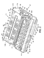
- FIG. 2 is an oblique view of the print assembly 11.
- FIG. 3 is a side section view of the dot impact printer 10 in FIG. 1 .
- the dot impact printer 10 shown in FIG. 1 records images, including text, by driving plural recording wires of a recording head 18 (see FIG. 3 ) against a recording medium S with an ink ribbon (not shown in the figure) delivered from a ribbon carriage (not shown in the figure) therebetween in order to form dots on the recording surface of the recording medium S.
- the dot impact printer 10 has an optical reader (scanner) 110 ( FIG. 3 ) and thus also functions as an optical reading device that can optically read text, symbols, images, and other content presented on the surface of the recording medium S.
- Cut-sheet media that is precut to a certain length, and continuous media having numerous sheets connected in a continuous web, are examples of recording media S (media) that can be used in the dot impact printer 10.
- Cut-sheet media include, for example, single slips and multipart forms, passbooks, postcards, and letters.
- Continuous media include continuous multipart form paper and perforated fanfold paper.
- checks and promissory notes (collectively referred to as simply checks herein) issued on a bank account, for example, and passbooks issued by a bank or other financial institution, are used as the recording medium S.
- Checks are slips on which MICR (magnetic ink character recognition) information containing the user's account number and a serial check number, for example, are printed in a MICR area MA on the check surface.
- a passbook is a bound booklet of plural blank pages that can be printed on when the passbook is open.
- a magnetic stripe is typically rendered on the outside surface of at least one of the passbook covers. Note that of the four sides of a rectangular recording medium S, the edge on the side that is inserted to the dot impact printer 10 is referred to herein as the leading edge or end, and the edge on the opposite side as the leading end is referred to as the trailing edge or end.
- the dot impact printer 10 has a top cover 12, a top case 13, and a bottom case 14 as outside case members, and a manual insertion opening 15 in the front of the top case 13 and bottom case 14 where the recording medium S is inserted and discharged.
- a paper exit 20 from which the recording medium S may be discharged is also formed at the back of the top case 13 and bottom case 14. Whether the recording medium S processed by the dot impact printer 10 is discharged from the manual insertion opening 15 or the paper exit 20 is controlled by a command sent from the host computer 200 described below to the dot impact printer 10.
- the side where the manual insertion opening 15 is rendered that is, the left side as seen in FIG.
- the dot impact printer 10 has a print assembly 11 that is covered by the foregoing case members.
- the print assembly 11 includes a bottom chassis part 11A and a top chassis part (not shown in the figure) that is supported by pins 11C at the back of the bottom chassis part 11A.
- the top chassis part can pivot by operating a lever (not shown in the figure) disposed on the left side of the top chassis part, and the inside of the print assembly 11 is exposed when the top chassis part pivots open.
- the print assembly 11 includes a base frame 16 and a right side frame 17A and left side frame 17B pair attached to the sides of the base frame 16.
- the side frames (not shown in the figure) of the top case chassis part are disposed on the outside of the side frames 17A and 17B with a carriage guide shaft 31 spanning therebetween and a flat front media guide 24 and rear media guide 25 affixed between the side frames 17A and 17B.
- a flat platen 21 is disposed between the front media guide 24 and rear media guide 25, and the recording head 18 is disposed above the platen 21 facing the platen 21.
- the recording head 18 is mounted on a carriage 19 that is fit freely slidably on the carriage guide shaft 31.
- the carriage 19 is driven by a timing belt (not shown in the figure) by driving a carriage drive motor 56 ( FIG. 4 ) that drives the carriage 19 forward or reverse, and the carriage 19 thus moves reciprocally guided by the carriage guide shaft 31.
- the carriage 19 scans bidirectionally between the side frames of the top chassis part in the direction indicated by arrow X in FIG. 1 , that is, in the main scanning direction aligned with the axial direction of the carriage guide shaft 31 and the long side of the platen 21.
- the direction perpendicular to the main scanning direction X of the carriage 19, that is, the direction indicated by arrow Y in FIG. 1 is the subscanning direction.
- the recording head 18 carried on the carriage 19 travels in the main scanning direction with the carriage 19, recording wires are pushed out from the wire face (not shown in the figure) on the distal end of the recording head 18 opposite the platen 21 to strike the ink ribbon and transfer ink from the ink ribbon to the recording medium S conveyed between the platen 21 and the recording head 18, and record an image, which may include text, on the recording medium S.
- the ink ribbon is stored folded up inside a ribbon cartridge (not shown in the figure) that is mounted on the main frame or the carriage 19, and is delivered to the recording head 18 while the carriage 19 scans the recording medium.
- a media width sensor 55 is disposed behind the recording head 18 at a position above the platen 21. The media width sensor 55 is mounted on the carriage 19 and travels with the carriage 19 over the platen 21, and is used to determine the positions of the side edges of the recording medium S and the width of the recording medium S.
- the platen 21 is flat and extends in the scanning direction of the carriage 19, and is urged toward the recording head 18 and elastically supported by an urging spring 180.
- the urging spring 180 is a compression spring, and the striking force of the recording wires during the recording operation of the recording head 18 is assisted by the urging force of the urging spring 180.
- the printer assembly 11 includes a media transportation mechanism (transportation means) 100 that conveys the recording medium S, an alignment mechanism 28 that contacts the leading end of the recording medium S conveyed by the media transportation mechanism 100 and aligns the recording medium S, a magnetic data reading unit 29 having a magnetic head 34 that reads the MICR information printed on a check or reads or writes magnetic information in the magnetic stripe on a passbook, and a media pressure unit 30 that pushes down on the recording medium S to prevent the recording medium S from lifting up during magnetic information processing, including when the magnetic head 34 of the magnetic data reading unit 29 reads the MICR information.
- a media transportation mechanism transportation means
- an alignment mechanism 28 that contacts the leading end of the recording medium S conveyed by the media transportation mechanism 100 and aligns the recording medium S
- a magnetic data reading unit 29 having a magnetic head 34 that reads the MICR information printed on a check or reads or writes magnetic information in the magnetic stripe on a passbook
- a media pressure unit 30 that pushes down on the recording medium S to
- the media transportation mechanism 100 includes the platen 21, a first drive roller 22A, a first follower roller 22B, a second drive roller 23A, a second follower roller 23B, a third drive roller 124A, a third follower roller 124B, the front media guide 24, the rear media guide 25, a media transportation motor 26, and a drive wheel train 27.
- the media transportation mechanism 100 renders a transportation path P through which the recording medium S is conveyed over the front media guide 24 and rear media guide 25.
- the tops of the front media guide 24 and rear media guide 25 are conveyance surface PA of the transportation path P.
- first drive roller 22A and first follower roller 22B are disposed on the front side of the printer assembly 11 relative to the platen 21 and recording head 18, and the second drive roller 23A and second follower roller 23B pair, and third drive roller 124A and third follower roller 124B pair, are disposed sequentially on the rear side of the printer assembly 11 relative to the platen 21 and recording head 18.
- the first drive roller 22A and first follower roller 22B are disposed as a roller pair one above the other, the second drive roller 23A and second follower roller 23B are disposed as a roller pair one above the other, and the third drive roller 124A and third follower roller 124B are disposed as a roller pair one above the other.
- the first drive roller 22A, second drive roller 23A, and third drive roller 124A are drive rollers that are driven rotationally by the media transportation motor 26 and drive wheel train 27.
- the first follower roller 22B, second follower roller 23B, and third follower roller 124B are follower rollers that are urged by springs 42A, 42B, and 42C with specific pressure to the first drive roller 22A, second drive roller 23A, and third drive roller 124A side, respectively.
- the first drive roller 22A and first follower roller 22B are rotationally driven in mutually opposite directions
- the second drive roller 23A and second follower roller 23B are rotationally driven in mutually opposite directions
- the third drive roller 124A and third follower roller 124B are rotationally driven in mutually opposite directions.
- the drive wheel train 27 is disposed on the outside of the right side frame 17A as shown in FIG. 2 .
- the drive wheel train 27 has a motor pinion 51 that is affixed to rotate in unison with the drive shaft of the media transportation motor 26, which can rotate in forward and reverse directions.
- Drive power from the motor pinion 51 is transferred through a speed reducing gear 52 to a second drive gear 53B affixed to the second roller shaft 33 of the second drive roller 23A, and is transferred from this second drive gear 53B through an intermediate gear 54 to a first drive gear 53A affixed to the first roller shaft 32 of the first drive roller 22A.
- Torque from the second roller shaft 33 of the second drive roller 23A is transferred to the third roller shaft 134 of the third drive roller 124A by a drive belt (not shown in the figure), for example.
- a drive belt (not shown in the figure), for example.
- the first drive roller 22A, second drive roller 23A, and third drive roller 124A shown in FIG. 3 rotate in the same direction and can convey the recording medium S in the printer assembly 11. More specifically, when the media transportation motor 26 rotates forward, the first drive roller 22A, second drive roller 23A, and third drive roller 124A shown in FIG.
- the alignment mechanism 28 aligns the recording medium S before the recording head 18 prints on the recording medium S and before the optical reader 110 scans the recording medium S.
- the alignment mechanism 28 includes plural alignment plates 38 and an alignment plate motor (see FIG. 4 ) that drives the alignment plates 38.
- the alignment plates 38 are arrayed in the main scanning direction between the first drive roller 22A and first follower roller 22B and the recording head 18 and platen 21, and can protrude into the transportation path P.
- the alignment plates 38 contact the leading end of the recording medium S and thereby align the orientation of the recording medium S.
- the printer assembly 11 has a plurality of alignment sensors 39 that detect the presence of the recording medium S driven in contact with the alignment plates 38.
- the alignment sensors 39 are disposed to the transportation path P arrayed in the main scanning direction near the upstream side of the alignment plates 38, and are transmissive sensors including a light-emitting unit (such as an LED) and a photodetection unit (such as a phototransistor) disposed with the transportation path P therebetween. Whether the skew of the recording medium S to the transportation direction after alignment by the alignment mechanism 28 is within the allowable range can be determined from the number and positions of the plural alignment sensors 39 that detect the leading end of the recording medium S.
- the dot impact printer 10 has a control circuit board (not shown in the figure) located behind and below the print assembly 11, for example, as a control unit that controls dot impact printer 10 operations, including driving the media transportation motor 26, carriage 19 scanning, the recording operation of the recording wires of the recording head 18, and the reading (scanning) operation of the optical reader 110.
- a control circuit board located behind and below the print assembly 11, for example, as a control unit that controls dot impact printer 10 operations, including driving the media transportation motor 26, carriage 19 scanning, the recording operation of the recording wires of the recording head 18, and the reading (scanning) operation of the optical reader 110.
- the printer assembly 11 also has a plurality of media edge sensors 47 that detect insertion of a recording medium S to the transportation path P in front of the first drive roller 22A.
- the media edge sensors 47 are reflective sensors having a light-emitting unit that emits light toward the transportation path P and a photodetection unit that detects the reflection of the emitted light, and detect the recording medium S inserted from the manual insertion opening 15.
- the media edge sensors 47 may alternatively be transmissive sensors having a light-emitting unit and a photodetection unit disposed with the transportation path P therebetween. This configuration determines that a recording medium S was inserted to the transportation path P when the photodetection units of all insertion detection sensors 47 sense light and then photodetection by any one of the insertion detection sensors 47 is blocked.
- the print assembly 11 has an optical reader 110 (optical reading unit) that reads text, symbols and images presented on the surface of the recording medium S.
- the optical reader 110 includes a first scanner 111 that reads information printed or otherwise presented on the top surface of the recording medium S, and a second scanner 112 disposed opposite the first scanner 111 that similarly reads information printed or otherwise presented on the bottom surface of the recording medium S.
- the recording medium S is normally inserted from the manual insertion opening 15 so that the side on which the MICR information is printed is the bottom surface.
- the first scanner 111 and second scanner 112 are optical image sensors that are disposed between the second drive roller 23A and third drive roller 124A and continuously read information on the recording medium S conveyed through the transportation path P.
- the first scanner 111 and second scanner 112 may be contact image sensors (CIS), for example, and respectively have a flat glass plate 140, 150 that contacts the recording medium S, and a support frame 141, 151 that supports the glass plate 140, 150.
- An emitter (not shown in the figure) that emits the scanning area of the recording medium S with light output from an LED or other light source, a plurality of photosensors (not shown in the figure) arrayed in a single row in the main scanning direction (X axis), and an output unit (not shown in the figure) that outputs the signals from the photosensors to the control circuit unit described above.
- the first scanner 111 and second scanner 112 are not limited to CIS scanners, however, and CCD (charge coupled device) scanners may be used instead.
- the second scanner 112 has a support frame 151 and glass plate 150 extending lengthwise across the width of the dot impact printer 10 parallel to the platen 21.
- the support frame 151 is disposed so that the top surface of the glass plate 150 is exposed to the transportation path P through a window formed in the rear media guide 25.
- the first scanner 111 is disposed above the second scanner 112 as shown in FIG. 3 so that the bottom surface of the glass plate 140 is opposite the glass plate 150, and likewise extends in the main scanning direction with substantially the same length as the second scanner 112.
- An urging member 113 is disposed above the first scanner 111, and the first scanner 111 is urged toward the recording medium S on the rear media guide 25 by the urging member 113.
- the urging member 113 pushes the first scanner 111 to the second scanner 112 with substantially uniform pressure across the width.
- a coil spring, flat spring, or elastomer cushion, for example, can be used as the urging member 113.
- a gap that accommodates recording media of a specific thickness is rendered between the surfaces of the glass plates 140, 150.
- the photosensors (not shown in the figure) of the first scanner 111 and second scanner 112 are arrayed in a row in the main scanning direction of the dot impact printer 10, and scan lines extending in the main scanning direction.
- the photosensors of the first scanner 111 and second scanner 112 are disposed across a wider range in the main scanning direction than the printing range of the recording head 18, and can scan a wider range than any recording medium that can be printed on by the dot impact printer 10.
- the optical reader 110 can therefore read the entire surface of any recording medium S that can be used in the dot impact printer 10.
- the first scanner 111 and second scanner 112 are disposed on opposite sides of the transportation path P as shown in FIG.
- the first scanner 111 and second scanner 112 each have R, G, and B light sources, and can scan in both monochrome (binary, 16 level, 256 level gray scale) and color modes.
- the scanning resolution of the first scanner 111 and second scanner 112 can be set to one of three levels, 200 dpi (dots/inch), 300 dpi, and 600 dpi.
- the number of scan lines in the transportation direction of the recording medium S (the subscanning direction) is set according to the scanning resolution in the main scanning direction, and the conveyance speed of the recording medium S during scanning is adjusted according such parameters as the scanning resolution and how fast the photosensor output signals can be processed.
- FIG. 4 is a block diagram showing the control configuration of the dot impact printer 10.
- the parts shown in FIG. 4 can be rendered by the cooperation of hardware components disposed to the control circuit board (not shown in the figure) and software.
- the dot impact printer 10 includes a CPU 40 as a control unit that controls the dot impact printer 10 based on a control program, RAM 41 that temporarily stores data and a control program read from EEPROM 42 by the CPU 40, EEPROM 42 that stores the control program executed by the CPU 40 and processed data, an interface 43 that converts the data format when communicating information with the host computer 200 that controls the dot impact printer 10, a gate array 45 connected to various sensors, a motor driver 46 that drives motors, a head driver 48 that drives heads, and a bus 49 to which these various parts are connected.
- RAM 41 functions as a storage unit, and renders an image buffer (not shown in the figure) that temporarily stores the image data captured by the optical reader 110.
- the CPU 40 also functions as a transmission unit that reads and transfers to the host computer 200 the image data stored in the image buffer rendered by RAM 41.
- the alignment sensors 39, media edge sensors 47, media width sensor 55, first scanner 111 and second scanner 112 are connected to the gate array 45.
- the gate array 45 quantizes the analog voltages input from the alignment sensors 39, media edge sensors 47, and media width sensor 55, and outputs the resulting digital data to the CPU 40.
- the first scanner 111 and second scanner 112 optically read the surface of the recording medium S using a CIS, supply the detection voltages from each pixel of the CIS to the gate array 45, and the gate array 45 quantizes the analog voltages supplied from the first scanner 111 and second scanner 112 and outputs the resulting digital data to the CPU 40.
- the motor driver 46 is connected to the media transportation motor 26, carriage drive motor 56, magnetic head drive motor 57, and alignment motor 58, supplies drive current and drive pulses to the motors, and thus causes the motors to operate.
- an alignment motor 58 FIG. 4
- the media edge sensors 47 is connected to the recording head 18 and magnetic head 34, and supplies drive current to the recording head 18 to drive the recording wires to print.
- the media edge sensors 47 also outputs drive current for reading and writing to the magnetic head 34, and when reading magnetic data detects and outputs the detection voltage (analog voltage) from the magnetic head 34 as digital data to the CPU 40.
- the CPU 40 acquires detection signals from the sensors and drives the motors to convey the recording medium S by means of the gate array 45, motor driver 46, and head driver 48 based on a control program stored in EEPROM 42, and drives the heads to record on the recording medium S.
- the CPU 40 also conveys the recording medium S by means of the media transportation mechanism 100, and reads the surface of the recording medium S by means of the gate array 45 and first scanner 111 and second scanner 112. While scanning, the CPU 40 temporarily stores the data input from the gate array 45 sequentially to a buffer (not shown in the figure) rendered in RAM 41.
- the CPU 40 also reads and outputs the image data stored in the buffer (not shown in the figure) to the host computer 200 through the interface 43.
- FIG. 5 shows an example of a check as a recording medium S that is processed by the dot impact printer 10.
- FIG. 5A shows the front and
- FIG. 5B shows the back of the check.
- the check used as the recording medium S is a horizontally long rectangle, is inserted to the dot impact printer 10 with one of the long sides at the leading edge, and is conveyed in the direction of the short side as shown in the figure. Note that the length (width) of the long side of the recording medium S is Lx below, and the length (height) of the short side is Ly. As shown in FIG.
- the surface of the recording medium S has fields for writing or printing the date, check amount, payee, name and address of the payer, a signature line, and a MICR area MA where MICR characters are printed.
- a check serial number may also be printed on the back of the recording medium S.
- FIG. 5B fields for writing or printing the account number and the name of the financial institution on which the check is drawn are provided, and a check serial number is printed, on the back of the recording medium S.
- the recording medium S shown in FIG. 5 is inserted from the manual insertion opening 15 to the dot impact printer 10 with the side shown in FIG. 5A facing down and the back shown in FIG. 5B facing up.
- the front side shown in FIG. 5A is therefore the bottom surface as referred to herein and is read by the second scanner 112, and the back side shown in FIG. 5B is the top surface read by the first scanner 111.
- the scanning range R of the first scanner 111 is set according to the size of the recording medium S, and is slightly greater than the width Lx and height Ly of the recording medium S as indicated by the dotted line in FIG. 5B .
- the width and height of the scanning range R are sized to add a scanning margin to the width Lx and height Ly of the recording medium S, and this scanning margin is typically a few millimeters, for example.
- the first scanner 111 can therefore optically scan the entire back of the recording medium S.
- the magnetic head 34 also reads the MICR text in the MICR area MA shown in FIG. 5A .
- the scanning range R of the second scanner 112 is similarly set according to the size of the recording medium S, and is slightly greater than the width Lx and height Ly of the recording medium S as indicated by the dotted line in FIG. 5A .
- the width and height of the scanning range R are sized to add a scanning margin to the width Lx and height Ly of the recording medium S, and this scanning margin is typically a few millimeters, for example.
- the first scanner 111 can therefore optically read the entire back of the recording medium S.
- the dot impact printer 10 reads the recording medium S by means of the optical reader 110 while conveying the recording medium S forward or reverse in the direction of the short side. The direction in which the recording medium S is conveyed while scanning is automatically determined so that scanning the part to the read can be completed with the shortest possible transportation distance.
- Commands are sent from the host computer 200 to the dot impact printer 10 through the interface 43, and the size (Lx, Ly) of the recording medium S to be scanned is set by command.
- the CPU 40 identifies the size of the recording medium S based on the command received from the host computer 200 and sets the scanning range R accordingly. Information identifying the location of the MICR area MA on the recording medium S is also contained in the command sent from the host computer 200.
- the location of the MICR area MA may be specified by the distance Dx from a short side of the recording medium S and the distance Dy from a long side, for example.
- the CPU 40 controls the motor driver 46 and head driver 48 based on the received command, and drives the magnetic head drive motor 57 to read with the magnetic head 34.
- the commands sent from the host computer 200 to the dot impact printer 10 include setup commands, a start scanning (reading) command, and an eject paper command.
- the setup commands are commands for specifying the scanning resolution of the optical reader 110, the scanning side (whether to scan the top or bottom), the scanning direction, the scanning mode (color or monochrome scanning), the number of gray levels if monochrome scanning is selected, the LED output color if monochrome scanning is selected, and the scanning area (the start and end points of the scanning area) if only part of the scanning range R is to be scanned.
- the coordinates of the start and end points of the scanning area are coordinates referenced to an origin at the left edge of the leading end of the scanning range R, for example.
- the setup commands also include a command that specifies whether or not to eject the recording medium S when the optical reader 110 finishes scanning even if the image data is still being transmitted to the host computer 200, and if the recording medium S is to be discharged, a command that specifies whether to discharge the recording medium S from the manual insertion opening 15 or the paper exit 20.
- the process of discharging the recording medium S while sending the image data captured by the optical reader 110 to the host computer 200 is referred to below as a "discharge during transmission process.”
- During transmission includes while determining if the host computer 200 can receive and while preparing to transmit, including the transmission setup process of the CPU 40.
- Whether or not to execute the discharge during transmission process, and whether to discharge the recording medium S from the manual insertion opening 15 or the paper exit 20, can be preset by the user using the host computer 200, in which case the setup command is generated to reflect the user setti ng.
- This discharge during transmission process shortens the total process time from scanning the recording medium S to discharging the recording medium S compared with the method of the related art in which the recording medium S is discharged after the recording medium S is scanned by the optical I reader 110, and thereby improves throughput. This discharge during transmission process is described in further detail below.
- the start scanning command is a command that tells the dot impact printer 10 to start the scanning process.
- the start scanning command includes information specifying the type of scanning operation, that is, a full scan that reads all of the scanning range R, or a partial scan that reads only the scanning area specified by the setup command.
- the CPU 40 controls the gate array 45 and motor driver 46 to start scanning by the optical reader 110.
- the discharge command is a command that specifies whether to discharge the recording medium S from the manual insertion opening 15 or paper exit 20 after scanning is completed, and includes a discharge instruction and information specifying the discharge direction (the manual insertion opening 15 or paper exit 20).
- the CPU 40 receives the discharge command, it discharges the recording medium S from the side specified by the discharge command.
- FIG. 6 illustrates the forward scanning operation of the dot impact printer 10.
- FIG. 6A shows the scanning direction
- FIG. 6B schematically describes scanning by the dot impact printer 10 in the full scan mode
- FIG. 6C schematically describes operation in the partial scan mode.
- the recording medium S passes the optical reader 110 and is scanned by the first scanner 111 and second scanner 112 while traveling from the front (the left in FIG. 2 ) of the dot impact printer 10 to the rear (the right in FIG. 2 ).
- the recording medium S is scanned from the leading end of the scanning range R (the top in the figure) to the trailing end (the bottom in the figure).
- the image data of the one line scanned by the first scanner 111 and second scanner 112 is output to the gate array 45 line by line sequentially from the left end of the scanning range R (the beginning of the arrow) to the right end (the tip of the arrow).
- the left end of the leading edge of the scanning range R is therefore the scanning start position, and the right end of the trailing edge is the end position.
- the CPU 40 divides the scanning range R into segments of a predetermined length in the scanning direction (subscanning direction) as shown in FIG. 6B . These segments are referred to as blocks.
- the scanning range R of the first scanner 111 and the scanning range R of the second scanner 112 are each segmented into plural blocks of a specified length, and the blocks are sequentially numbered alternately top and bottom from the leading end of the scanning direction. More specifically, the first block of the scanning range R on the top is block 1, the first block of the scanning range R on the bottom is block 2, and the remaining blocks are similarly numbered alternating top and bottom in the scanning direction 3, 4, ... 8 as shown in the figure.
- the length of the last block is the length of the block remaining after dividing the scanning range R into blocks of the specified length.
- Each block is the size of the process unit in which the image data from the first scanner 111 and second scanner 112 is sent to the host computer 200. That is, each time the image data for one block is stored in the image buffer (not shown in the figure) in RAM 41, the CPU 40 sends the image data for that block to the host computer 200.
- the specified length that is, the length of each block in the transportation direction (scanning direction) is determined according to the capacity of the image buffer (not shown in the figure) reserved in RAM 41. For example, if the image buffer has sufficient capacity to store 300 lines of full-color image data at the maximum resolution of 600 dpi, the length of one block is set appropriately to a length of 300 lines or less.
- the CPU 40 controls the motor driver 46 to drive the media transportation motor 26 to convey the recording medium S at a specified speed while controlling the gate array 45 and driving the light sources of the first scanner 111 and second scanner 112 to generate the scanned image data based on the detection values from the photosensors and storing the scanned image data line by line to the image buffer in RAM 41.
- the CPU 40 continues this operation without interrupting conveying the recording medium S until the entire scanning range R is read by the first scanner 111 and second scanner 112.
- the CPU 40 reads and sends the image data for that block from the image buffer to the host computer 200, and then deletes the scanned image data from the image buffer after transmission is completed. Deleting the scanned image data creates a large empty space in the image buffer again so that the next image data captured next can be stored.
- the CPU 40 sends the captured image data to the host computer 200 as described above.
- the order in which the image data captured from each block is sent is the order in which scanning is completed, and is not limited to the order of the block numbers.
- the CPU 40 sends the scanned image data to the host computer 200, it also sends additional information in a header indicating which side was scanned (top or bottom), the size of the scanned block, the block number, and the data length. lf the image data is large, the CPU 40 can send the image data for one block in smaller segments, in which case information enabling the host computer 200 to rejoin the image data segments may also be added to the header.
- the CPU 40 sets the area to be scanned according to the scanning area specified in the scanning range R by the setup command as shown in FIG. 6C .
- areas A1 and A2 are set in the scanning range R of the top
- area A3 is set in the scanning range R of the bottom side of the recording medium S.
- the CPU 40 configures the scan blocks according to the partial scan areas. If the length of an area in the scanning direction is shorter than the predetermined length of one block described above, the CPU 40 produces one block for the one area. The leading end and the trailing end of this block match the leading end and trailing end of the area.
- the CPU 40 segments the scanning area into blocks of the specified length starting from the leading end of the area in the scanning direction.
- areas A1 and A3 exceed the predetermined block length, area A1 is therefore divided into blocks 1 and 3, and area A3 is divided into blocks 2 and 4.
- the block numbers are assigned sequentially from the leading end of the first block alternating top and bottom in the same way as in the full scan mode. Note that when there are plural scan areas defined across the width of the scanning range R, and the areas overlap in the scanning direction, all of the overlapping areas are treated as a single block. If the length of such a block in the scanning direction exceeds the maximum length of one block, the block is segmented into plural blocks in the scanning direction.
- the CPU 40 then starts scanning areas A1 to A3 in the scanning range R.
- the CPU 40 controls the gate array 45 and motor driver 46 and continues the scanning operation without interrupting transportation of the recording medium S until all areas have been scanned by the first scanner 111 and second scanner 112.
- the CPU 40 reads and sends the image data for that block from the image buffer to the host computer 200, and then deletes the image data from the image buffer after data transmission is completed.
- the transmission sequence in this case is the same as during the full scan mode, that is, in the order in which block scanning is completed and is not limited to the order of the block numbers.
- the CPU 40 When the CPU 40 sends the scanned image data to the host computer 200, it also sends additional information in a header indicating which side was scanned (top or bottom), the size of the scanned block, the block number, the data length, the area number, and the coordinates of the beginning and end positions of the area. If a single area is divided into plural blocks, information for rejoining the blocks constituting each area may also be included. In addition, if plural areas are contained in one block, the CPU 40 divides the scanned image data for the block into the individual areas, and sends the image data for each area to the host computer 200. If the size of the captured image data is large, the data can also be divided into smaller units for transmission to the host computer 200 in this partial scan mode.
- the host computer 200 receives the scanned image data sent from the dot impact printer 10, and reconstructs the scanned image block by block based on the header information.
- the host computer 200 specifies the full scan mode in the setup command sent to the dot impact printer 10, it reproduces images for the entire scanning range R of both the top and bottom sides by rejoining the blocks.
- the host computer 200 reproduces the scanned image data for each area by rejoining the blocks when a single area is divided into plural blocks, and using the scanned image data contained in each block as is when a single block constitutes a single area.
- FIG. 7 illustrates the reverse scanning operation of the dot impact printer 10.
- FIG. 7A shows the scanning direction
- FIG. 7B schematically describes scanning in the full scan mode
- FIG. 6C schematically describes operation in the partial scan mode.
- the recording medium S passes the optical reader 110 and is scanned by the first scanner 111 and second scanner 112 while traveling from the rear of the dot impact printer 10 to the front. ln this case scanning proceeds from the trailing end of the scanning range R as shown in FIG. 7A (the bottom end in the figure) to the leading end (the top end in the figure).
- the left end of trailing edge of the scanning range R is the scanning start position and the right edge of the leading end is the end position.
- the scanning range R is segmented into blocks from the trailing end as shown in FIG. 7B .
- the block numbers are assigned sequentially from the end at the leading edge during scanning while alternating top and bottom. Other aspects of the operation are the same as during a full scan in the forward direction.
- the areas to be scanned are configured based on the setup command received from the host computer 200 as shown in FIG. 7C , and the areas are segmented into blocks from the trailing end of the scanning range R, which is the leading end in the scanning direction. Areas that exceed the maximum length of one block are divided into blocks of the specified length referenced to the trailing end of the scanning range R.
- the CPU 40 of the dot impact printer 10 may execute a process to invert the image data before transmission to the paper exit 20, but because the host computer 200 that sent the setup command has information about the scanning direction, the host computer 200 can use this information to rotate the scanned image data 180 degrees.
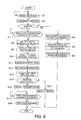
- FIG. 8 is a flow chart describing the operation of the dot impact printer 10 according to this embodiment of the invention.
- the CPU 40 functions as a transmission control unit in the following operation.
- the CPU 40 of the dot impact printer 10 drives the alignment plate 38 to protrude into the transportation path P of the recording medium S and operates the media transportation motor 26 to align the recording medium S (step S2).
- the CPU 40 determines whether the detected recording medium S is a check or a passbook (step S3).
- the CPU 40 can determine the type of recording medium S based on information acquired from the host computer 200. Alternatively, the CPU 40 can detect the locations of the leading end and side of the recording medium S using the media edge sensors 47 and media width sensor 55, and determine the type of recording medium S based on this position and size information. Further alternatively, based on the positions of the leading end and side of the recording medium S detected using the media edge sensors 47 and media width sensor 55, the CPU 40 may attempt to read the MICR information using the magnetic head 34, and determine the type of recording medium S by determining whether or not MICR information is found in the MICR area MA by this reading attempt.
- the CPU 40 acquires from the host computer 200 information identifying the type of recording medium S (check or passbook), information such as the size of the check if the recording medium S is a check, information about the location of the MICR area MA, and information about the transportation distance, and determines based on the received information whether the recording medium S is a check or a passbook.
- step S3 If the recording medium S is not a check (step S3 returns No) and the CPU 40 determines that the recording medium S is a passbook, for example, it conveys the recording medium S to the position where the magnetic stripe on the passbook can be read by the magnetic head 34, and then reads and/or writes the magnetic stripe by means of the magnetic head 34 (step S4).
- the CPU 40 then conveys the recording medium S to the position of the recording head 18, records on the recording surface by means of the recording head 18 (step S5), and then discharges the recording medium S from the manual insertion opening 15 (step S6) to complete the process.
- step S7 determines if a MICR information read command was received from the host computer 200 (step S7). lf the CPU 40 determines that a MICR read command was received (step S7 returns Yes), it retracts the alignment plate 38 from the transportation path P, conveys the recording medium S by means of the media transportation mechanism 100 until at least the leading end of the recording medium S is directly below the media width sensor 55, then drives the carriage drive motor 56 ( FIG. 5 ) to move the carriage 19 in the main scanning direction, and detects the widthwise position of the recording medium S based on the output signals from the media width sensor 55 and the position of the carriage 19 in the main scanning direction (step S8). The CPU 40 then monitors the output signals from the media edge sensors 47 while conveying the recording medium S by means of the media transportation mechanism 100, and detects the trailing end of the recording medium S (step S9).
- the CPU 40 then conveys the recording medium S by means of the media transportation mechanism 100 to the position where the MICR area MA can be read by the magnetic head 34 (step S10), controls the motor driver 46 to operate the magnetic head drive motor 57, and and reads the MICR text in the MICR area MA by means of the magnetic head 34 (step S11).
- the MICR information read by the magnetic head 34 is then digitized by the gate array 45, and the CPU 40 acquires the output digital data (step S12).
- the CPU 40 then extracts the character data from the digital data and converts it to text information (step S13). Whether the number of characters in the extracted text exceeds a predetermined number, or whether the character count is within the range of the predetermined count and reading the MICR information was successful, is then determined (step S14).
- step S14 If the number of characters exceeds the predetermined count and there is an unreadable character (step S14 returns No), an error is output, the recording medium S is discharged (step S15), and operation ends.
- the error can be reported in step S15 using a display unit disposed to the dot impact printer 10, sending information indicating that an error occurred to the host computer 200, or using both methods.
- step S14 If the number of interpreted characters does not exceed the preset count and reading was successful (step S14 returns Yes), the CPU 40 scans the recording medium S using the optical reader 110 and sends the captured image data to the host computer 200 (step S16). The CPU 40 then waits to receive a command to print an endorsement on the back from the host computer 200 (step S17). When an endorsement print command is received (step S17 returns Yes), the CPU 40 reverses the media transportation motor 26 to convey the recording medium S to below the recording head 18, and then drives the carriage drive motor 56 and recording head 18 to print an endorsement indicating that the check was processed on the back of the recording medium S (step S18). When printing the endorsement is completed, the CPU 40 drives the media transportation motor 26 again to discharge the recording medium S from the manual insertion opening 15 or the paper exit 20. Note that if a command to execute the discharge during transmission process is contained in the setup command as described below, the recording medium S is discharged after scanning is completed, and step S17 and step S18 are therefore not executed.
- FIG. 9 is a flow chart of the scanning operation executed by the dot impact printer 10, and describes the operation executed in step S16 in FIG. 8 in further detail.
- the CPU 40 functions as a discharge control unit.
- the CPU 40 receives the setup command sent from the host computer 200 (step S21), and acquires the settings content specified by the setup command (step S22).
- the setup command includes a command indicating whether or not to execute the discharge during transmission process, and if the discharge during transmission process is to be executed, a command specifying whether to discharge the recording medium S from the manual insertion opening 15 or paper exit 20.
- the CPU 40 determines if the area to be scanned is specified in the setup command (step S23).
- step S23 If the scanning area is not specified (step S23 returns No), it acquires the position of the block referenced to scan the entire scanning range R based on the scanning direction specified in the setup p command (step S24).
- the position of the reference block used for a full scan of the scanning range R is stored in EEPROM 42, for example. If a specific scanning area is specified in the setup command (step S23 returns Yes), the CPU 40 acquires the area numbers and the coordinates of the start and end positions of each area (step S24), positions the areas in the scanning range R, and determines the positions of the blocks for each area based on the scanning direction specified in the setup command (step S26).
- the CPU 40 waits to receive a start scanning command from the host computer 200 (step S27).
- a start scanning command is received (step S27 returns Yes)
- the CPU 40 conveys the recording medium S to the scanning start position of the optical reader 110 by means of the media transportation mechanism 100 based on the scanning direction specified in the setup command, whether a full scan or partial scan is specified, the position of the specified area if a partial scan is specified, and the current position of the recording medium S (step S28), and scans while conveying the recording medium S by means of the first scanner 111 and second scanner 112 (step S29). While scanning continues the CPU 40 determines if there is a block for which scanning is not completed (step S30).
- step S30 If there is a block for which scanning is completed (step S30 returns Yes), the CPU 40 starts the process of reading and sending the image data captured for that block from the image buffer in RAM 41 to the host computer 200 (step S31), and then deletes the image data for that block from the image buffer after data transmission is completed. The CPU 40 then determines if scanning all blocks was completed (step S32). If there is a block for which scanning is not completed (step S32 returns No), the CPU 40 returns to step S29, continues scanning, and if a new block for which scanning is completed is detected, sends the image data for that block to the host computer 200.
- step S32 When scanning all blocks in the scanning range R of both top and bottom sides is completed (step S32 returns Yes), the CPU 40 determines whether or not to execute the discharge during transmission process based on the settings acquired in step S22 (step S34). lf the discharge during transmission process is not executed (step S34 returns No), the CPU 40 monitors whether or not transmitting the image data for all blocks to the host computer 200 was completed (step S35). If transmission is completed (step S35 returns Yes), scanning ends and control goes to step S17 in FIG. 8 . However, if the discharge during transmission process is executed (step S34 returns Yes), the CPU 40 determines whether the recording medium S is to be discharged from the manual insertion opening 15 or paper exit 20 (step S36).
- step S36 If discharge from the manual insertion opening 15 is instructed (step S36 returns "manual insertion opening"), the CPU 40 controls the media transportation motor 26 to discharge the recording medium S from the manual insertion opening 15 (step S37). If discharge from the paper exit 20 is instructed (step S36 returns "paper exit"), the CPU 40 controls the media transportation motor 26 to discharge the recording medium S from the paper exit 20 (step S38).
- the process of discharging the recording medium S in step S37 and step S38 is executed even if the captured image data is being transmitted. That is, the recording medium S is discharged after the optical reader 110 finishes scanning the recording medium S even if the captured image data is still being transmitted to the host computer 200. After the recording medium S is discharged, the CPU 40 monitors whether transmitting the captured image data is completed (step S39), and ends the process if data transmission is completed (step S39 returns Yes).
- the discharge during transmission process thus discharges the recording medium S immediately after the optical reader 110 finishes scanning the recording medium S even if the the captured image data is still being transmitted to the host computer 200.
- the time required by the entire process can be shortened and throughput can be improved compared with the method of the related art in which transmitting the captured image data starts after scanning the recording medium S is completed and the recording medium S is only discharged after transmitting the image data is completed.
- the CPU 40 also executes the discharge during transmission process appropriately after determining whether or not to execute the discharge during transmission process based on a setup command input from the host computer 200 before the optical reader 110 scans the recording medium S.
- the CPU 40 could alternatively output data indicating that scanning the recording medium S was completed to the host computer 200 based on a predetermined protocol, the host computer 200 could then return a command to start the recording medium S discharge operation to the CPU 40, and as a result the recording medium S could be discharged immediately after scanning the recording medium S is completed even if the captured image data is still being transmitted to the host computer 200. While this configuration can improve throughput, it also requires the CPU 40 and host computer 200 to exchange information according to a predetermined protocol after the optical reader 110 finishes scanning the recording medium S, thus complicating the process and inviting a drop in efficiency.
- the invention includes a command specifying whether or not to execute the discharge during transmission process in the setup command that is input to the CPU 40 before the optical reader 110 scans the recording medium S, the CPU 40 executes the discharge during transmission process based on this command, and the discharge during transmission process can therefore be executed smoothly and reliably.
- the photosensors of the first scanner 111 and second scanner 112 are offset with the first scanner 111 positioned approximately 5 mm in front in this embodiment of the invention.
- scanning the scanning range R on the top side is completed before the scanning range R on the bottom is completed when scanning in the forward direction, and when scanning in reverse scanning the scanning range R on the bottom is completed before scanning the scanning range R on the top is completed.
- the CPU 40 drives the optical reader 110 to read blocks defined in the scanning range R of the optical reader 110, and when the optical reader 110 finishes scanning any block, reads and sends the image data for the block for which scanning was completed from the image buffer of the RAM 41 even if scanning other blocks is not completed. Because data transmission thus does not wait until scanning all blocks is completed, the wait associated with image data transmission can be shortened. As a result, the overall scanning process can be accelerated and convenience can be improved. More particularly, the waiting time can be greatly shortened when the captured image data is large, such as when the scanning resolution is high or during a full-color scan. Yet further, the capacity of the image buffer in RAM 41 only needs to be sufficient to store the image data captured for one block, and less storage capacity is needed than if the image data captured for the entire scanning range R is stored.
- the optical reader 110 has a first scanner 111 that reads one side of the recording medium S and a second scanner 112 that reads the other side of the recording medium S disposed on opposite sides of the transportation path P so that both sides of the recording medium S can be scanned.
- the CPU 40 drives the optical reader 110 to scan blocks set in the scanning range R of the first scanner 111 and second scanner 112, and when scanning any block is completed, reads and sends the image data for the block for which scanning was completed from the image buffer even if scanning a block set in the scanning range R on the same side or set in the scanning range R of the other side is not completed.
- the wait time associated with transmitting the scanned image data can be shortened, and both sides of the recording medium S can be scanned more quickly.
- the capacity of the image buffer in RAM 41 can be smaller than the capacity required to store the image data captured from both sides.
- the CPU 40 sets the blocks for areas exceeding the specified block length by dividing the area into segments of the specified length, and when the optical reader 110 finishes scanning any block, reads and transmits the image data for the block for which scanning was completed from the image buffer.
- the CPU 40 segments the specified area into blocks, and when sending the image data for a block to the host computer 200 adds and sends information identifying the original area to which the block belongs.
- the host computer 200 receiving the image data can therefore reassemble an image of the complete specified area from the image data divided into blocks.
- the CPU 40 divides the scanning range R into plural blocks and transmits the scanned image data in block units. Delaying transmission until scanning the entire scanning range R is completed is therefore not necessary, and the wait time associated with image data transmission can be shortened.
- the wait time can be automatically shortened even without executing an operation or command for setting the positions of the blocks, and convenience can be further improved.
- the CPU 40 is configured to selectively execute a full scan that scans the entire scanning range R, or a partial scan that scans part of the scanning range R, based on a setup command and start scanning command sent from the host computer 200.
- a full scan is selected, the CPU 40 divides the scanning range R into a plurality of blocks, and when a partial scan is selected, configures the blocks based on the area specified for scanning in the scanning range R.
- the CPU 40 then sequentially scans the blocks by means of the optical reader 110, and when scanning any block is completed, reads and sends the image data captured from the block for which scanning was completed from the image buffer in RAM 41 even if it is before scanning another block is completed.
- the area is segmented into blocks of the specified length.
- the wait time associated with transmitting the scanned image data can be shortened and convenience can be improved whether scanning the entire scanning range R or scanning only an area in one part of the scanning range R.
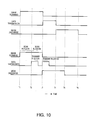
- FIG. 10 is a timing chart of the operation from scanning an image by means of the optical reader 110 to discharge of the recording medium S.
- FIG. 10A is a timing chart of this operation when executed by a dot impact printer according to the related art
- FIG. 10B is a timing chart of the operation when executed by the dot impact printer 10 according to this embodiment of the invention.
- the scanning range is divided into two blocks (block B1 and block B2) in this example.
- the timing of the operation of a dot impact printer according to the related art is described first with reference to FIG. 10A.
- the optical reader 110 of the dot impact printer according to the related art starts scanning block B1 and block B2 in the recording medium S at time T1, and finishes scanning block B1 and block B2 at time T3.
- Transmission of the image data captured from block B1 and block B2 to the host computer 200 then starts at time T3 simultaneously to finishing scanning the recording medium S, and transmission of the image data is completed at time T4.
- the operation of discharging the recording medium S then starts at time T4 simultaneously to the end of image data transmission, and the discharge operation ends at time T6.
- the optical reader 110 starts scanning the recording medium S at time T1 as shown in FIG. 10B, and when capturing an image of block B1 is completed at time T2, sending the image data for block B1 to the host computer 200 starts before scanning block B2 is completed. Sending the image data for block B2 to the host computer 200 then starts when scanning block B2 ends at time T3. The operation of discharging the recording medium S then starts simultaneously to the completion of scanning block B2 at time T3. This discharge operation executes while transmitting the image data captured for block B2 to the host computer 200, and ends at time T5. As will be obvious from FIG. 10A and FIG.
- transmission of the image data for all scanned blocks is completed sooner with the dot impact printer 10 according to this embodiment of the invention than with the dot impact printer according to the related art.
- the timing of the completion of the operation discharging the recording medium S is earlier in the dot impact printer 10 according to this embodiment of the invention than the dot impact printer according to the related art. More specifically, the time of the process including scanning the recording medium S, sending the image data captured for the scanned image, and discharging the recording medium S can be shortened and throughput can be improved.
- the user can use the time saved to ready and set the recording medium S to be processed next in the dot impact printer 10, file the discharged recording medium S, or perform other tasks, thereby improving convenience.
- the CPU 40 that functions as a discharge control unit in the foregoing embodiment controls the media transportation motor 26 to discharge the recording medium S from the manual insertion opening 15 or paper exit 20 while sending at least the captured image data to the host computer 200.
- the recording medium S can be discharged while sending the captured image data to the host computer 200, and throughput can be improved compared with the related art in which the discharge operation executes after transmitting the captured image data ends.
- transmission of captured image data to the host computer 200 obviously includes data transmission preparation time.
- scanning the recording medium S includes scanning either or both sides.
- the CPU 40 that functions as a discharge control unit in the foregoing embodiment executes the recording medium S discharge operation based on a setup command input from the host computer 200 before the optical reader 110 scans the surface of the recording medium S. As a result, the CPU 40 can smoothly and reliably selectively discharge the recording medium S while transmitting the image data based on a setup command that is input before the recording medium is scanned.
- the dot impact printer 10 has two paper exits, a manual insertion opening 15 and paper exit 20, as exits from which the recording medium S can be discharged.
- a command specifying whether to discharge the recording medium S from the manual insertion opening 15 or paper exit 20 is also contained in the setup command.
- the CPU 40 that functions as a discharge control unit can smoothly and reliably discharge the recording medium S from the desired paper exit, that is, either the manual insertion opening 15 or paper exit 20, while transmitting the captured image data.
- the CPU 40 of a dot impact printer 10 functions as a transmission control unit that, when a optical reader 110 scans one or a plurality of areas set input terminal the scanning range of the optical reader 110 and finishes scanning any area, reads and transmits the captured image data for the area for which scanning was finished from RAM 41 to the host computer 200 even if before scanning another area is finished.
- the CPU 40 functioning as the discharge control unit also discharges the recording medium S while transmitting at least the captured image data to another device.
- the CPU 40 functioning as a transmission control unit transmits the captured image data from the area for which scanning was completed even if there is another area for which scanning is not completed. Transmission therefore does not wait until scanning all areas is completed, the time associated with transmitting the captured image data can be shortened, and throughput can be improved.
- a preferred embodiment of the invention is described above, but the invention is not limited thereto.
- a configuration in which the alignment mechanism 28, recording head 18, and optical reader 110 are disposed in this order to the transportation path P of the recording medium S is described in the foregoing embodiment, but the invention is not so limited and the locations of these devices can be changed as desired.
- the optical reader 110 could be disposed closest to the manual insertion opening 15.
- the foregoing embodiment describes a control unit that is disposed to a control circuit board (not shown in the figure) installed in the dot impact printer 10, has the functions shown in the function blocks in FIG. 4 , and controls other parts of the dot impact printer 10, but a device externally connected to the dot impact printer 10 could function as the function units shown in FIG. 4 and control operation of the dot impact printer 10.
- the function blocks shown in FIG. 4 are rendered by cooperation of hardware and software components, but the specific configuration of the hardware component and the specifications of the software component are not limited, and the detailed configurations thereof can be changed as desired.
- first scanner 111 and second scanner 112 in the foregoing embodiment are described as using RGB light sources to enable monochrome or color scanning, but a configuration using an infrared light source to enable infrared scanning is also conceivable.
- infrared light can be used to read only the characters printed in magnetic ink, thereby enabling optically reading the MICR text in the MICR area MA efficiently.
- the magnetic head 34 can be controlled to read the identified area.
- the foregoing embodiment describes the invention applied to a flatbed scanner that conveys the recording medium S horizontally, but the invention is not so limited and can obviously be applied to a device with a transportation path that conveys recording media S such as checks and slips standing vertically on edge.
- the foregoing embodiment also describes a dot impact printer 10 having an optical reader 110, but the invention is not so limited and can obviously be applied to other configurations having an optical reading unit comparable to the optical reader 110 disposed to an inkjet printer, thermal printer, or laser printer, for example.
- the invention is not limited to devices that are used as a stand-alone printer, and configurations having an optical reading unit comparable to the optical reader 110 disposed in another device (such as an ATM (automated teller machine) or CD (cash dispenser)) are also conceivable. Yet further, the invention is not limited to configurations rendering an optical reader 110 in unison with a device that records text or images on paper or other recording medium, and can obviously be applied to a wide range of other devices including stand-alone scanners and photocopiers.
Landscapes
- Engineering & Computer Science (AREA)
- Multimedia (AREA)
- Signal Processing (AREA)
- General Engineering & Computer Science (AREA)
- Computing Systems (AREA)
- Facsimile Scanning Arrangements (AREA)
- Facsimiles In General (AREA)
Abstract
Description
- The present invention relates to an optical reading device that conveys a medium and optically reads (optically scans) the surface of the medium, to a method of controlling the optical reading device, and to a program.
- Japanese Unexamined Patent Appl. Pub.
JP-A-2009-284191 JP-A-2009-284191 - An optical reading device such as taught in
JP-A-2009-284191 - The invention advantageously enables to shorten the time consumed by the process from image scanning by the optical reading means through media discharge and improves throughput.
- A first aspect of the invention is an optical reading device including a transportation means that conveys a medium to be scanned along a medium transportation path; an optical reading means that is disposed to the medium transportation path and optically reads (optically scans) the medium conveyed along the medium transportation path by the transportation means; a storage means that stores an image captured (optically scanned) by the optical reading means; a transmission means that reads and/or transmits the captured (scanned) image stored in the storage means to another device such as an external device; and a discharge control means that controls the transportation means and discharges the medium while the transmission means is transmitting at least the captured (scanned) image to the other (external) device after optically scanning the medium by the optical reading means is completed.
This aspect of the invention enables discharging the scanned medium by means of the discharge control means during transmission of the captured image, including transmission preparation time, by the transmission means, and can improve the throughput of the overall process compared with the related art in which the discharge operation is executed after transmission of the captured image is completed. Scanning the medium includes scanning at least parts of the top, the bottom, or both sides of the medium. - In an optical reading device according to another preferable aspect of the invention, the discharge control means may control the transportation means based on a command that is received from the other (external) device before the optical reading means optically scans the medium, and/or specifies whether or not to discharge the medium while the captured (scanned) image is being transmitted.
With this aspect of the invention the discharge control means can smoothly and reliably selectively discharge the medium during captured image transmission based on a command that is input before the medium is scanned. - An optical reading device according to another preferable aspect of the invention also has a plurality of media exits from which the medium may be discharged, and the command may include information specifying from which of the plural media exits the medium is to be discharged.
With this aspect of the invention the discharge control means can smoothly and reliably discharge the medium from the desired one of plural discharge exits while the captured image is being transmitted. - An optical reading device according to another aspect of the invention preferably also has a transmission control means that controls the optical reading means and the transmission means, causes the optical reading means to optically read (optically scan) one or a plurality of areas set in the scanning range of the optical reading means, and/or when scanning at least one area is completed, reads and transmits the captured (scanned) image of the area for which scanning was completed from the storage means to the other (external) device even if before scanning another area is completed, that is even before scanning another area is yet completed; and the discharge control means may control the transportation means and may discharge the medium while the transmission control means sends (transmits) at least the captured (scanned) image to the other (external) device.
When an area set in the scanning range is optically read, the captured image is stored, and scanning at least one area is completed, the transmission control means in this aspect of the invention transmits the captured image of the area for which scanning was completed even if there is another area where scanning is not yet completed. As a result, transmission does not wait until scanning all areas is completed, the time associated with transmitting the captured image can be shortened, and throughput can be improved. - Another aspect of the invention is a method of controlling an optical reading device, including steps of:
- controlling an optical reading device according to at least one of the above-mentioned aspects including at least the transportation means, the optical reading means, the storage means, and the transmission means of the optical reading device of the first aspect;
- causing the optical reading means to scan the medium; and
- controlling the transportation means and discharging the medium while the transmission means is transmitting at least the captured (scanned) image to the other (external) device after scanning of the medium is completed.
- Another aspect of the invention is a program that can be executed by a control means that controls an optical reading device according to at least one of the above-mentioned aspects including at least the transportation means, the optical reading means, the storage means, and the transmission means of the optical reading device of the first aspect. The program is adapted to cause the control means to function as a discharge control means that controls the transportation means and discharges the medium while the transmission means is transmitting at least the captured (scanned) image to the other (external) device after scanning the medium by the optical reading means is completed.
Executing this program enables discharging the scanned medium during transmission of the captured image, including transmission preparation time, by the transmission means, and can improve throughput compared with the related art in which the discharge operation is executed after transmission of the captured image is completed. - The invention can shorten the time of the process from capturing an image by means of an optical reading means to discharging the medium, and can improve throughput.
Other objects and attainments together with a fuller understanding of the invention will become apparent and appreciated by referring to the following description and claims taken in conjunction with the accompanying drawings. -
-
FIG. 1 is an external oblique view of a dot impact printer according to a preferred embodiment of the invention. -
FIG. 2 is an oblique view of the print assembly. -
FIG. 3 is a section view of the print assembly. -
FIG. 4 is a block diagram showing the functional configuration of the dot impact printer. -
FIG. 5 shows an example of a medium to be scanned. -
FIG. 6 describes the scanning operation using an optical scanner. -
FIG. 7 describes the scanning operation using an optical scanner. -
FIG. 8 is a flow chart of the operation of the dot impact printer. -
FIG. 9 is a flow chart of the operation of the dot impact printer. -
FIG. 10 is a timing chart of the operation of the dot impact printer. - A preferred embodiment of the present invention is described below with reference to the accompanying figures.
FIG. 1 is a front oblique view showing the appearance of a dot impact printer according to a preferred embodiment of the invention.FIG. 2 is an oblique view of theprint assembly 11.FIG. 3 is a side section view of thedot impact printer 10 inFIG. 1 .
Thedot impact printer 10 shown inFIG. 1 records images, including text, by driving plural recording wires of a recording head 18 (seeFIG. 3 ) against a recording medium S with an ink ribbon (not shown in the figure) delivered from a ribbon carriage (not shown in the figure) therebetween in order to form dots on the recording surface of the recording medium S. Thedot impact printer 10 has an optical reader (scanner) 110 (FIG. 3 ) and thus also functions as an optical reading device that can optically read text, symbols, images, and other content presented on the surface of the recording medium S. - Cut-sheet media that is precut to a certain length, and continuous media having numerous sheets connected in a continuous web, are examples of recording media S (media) that can be used in the
dot impact printer 10. Cut-sheet media include, for example, single slips and multipart forms, passbooks, postcards, and letters. Continuous media include continuous multipart form paper and perforated fanfold paper. In this embodiment of the invention checks and promissory notes (collectively referred to as simply checks herein) issued on a bank account, for example, and passbooks issued by a bank or other financial institution, are used as the recording medium S.
Checks are slips on which MICR (magnetic ink character recognition) information containing the user's account number and a serial check number, for example, are printed in a MICR area MA on the check surface. A passbook is a bound booklet of plural blank pages that can be printed on when the passbook is open. A magnetic stripe is typically rendered on the outside surface of at least one of the passbook covers.
Note that of the four sides of a rectangular recording medium S, the edge on the side that is inserted to thedot impact printer 10 is referred to herein as the leading edge or end, and the edge on the opposite side as the leading end is referred to as the trailing edge or end. - As shown in
FIG. 1 , thedot impact printer 10 has atop cover 12, atop case 13, and abottom case 14 as outside case members, and a manual insertion opening 15 in the front of thetop case 13 andbottom case 14 where the recording medium S is inserted and discharged. Apaper exit 20 from which the recording medium S may be discharged is also formed at the back of thetop case 13 andbottom case 14. Whether the recording medium S processed by thedot impact printer 10 is discharged from themanual insertion opening 15 or thepaper exit 20 is controlled by a command sent from thehost computer 200 described below to thedot impact printer 10.
The side where the manual insertion opening 15 is rendered, that is, the left side as seen inFIG. 3 , is referred to herein as the front, and the side where thepaper exit 20 is rendered, that is, the right side inFIG. 3 , is referred as the rear.
As shown inFIG. 2 , thedot impact printer 10 has aprint assembly 11 that is covered by the foregoing case members. Theprint assembly 11 includes abottom chassis part 11A and a top chassis part (not shown in the figure) that is supported bypins 11C at the back of thebottom chassis part 11A. The top chassis part can pivot by operating a lever (not shown in the figure) disposed on the left side of the top chassis part, and the inside of theprint assembly 11 is exposed when the top chassis part pivots open. - As shown in
FIG. 2 andFIG. 3 , theprint assembly 11 includes abase frame 16 and aright side frame 17A andleft side frame 17B pair attached to the sides of thebase frame 16. The side frames (not shown in the figure) of the top case chassis part are disposed on the outside of the side frames 17A and 17B with acarriage guide shaft 31 spanning therebetween and a flat front media guide 24 and rear media guide 25 affixed between the side frames 17A and 17B. Aflat platen 21 is disposed between the front media guide 24 and rear media guide 25, and therecording head 18 is disposed above theplaten 21 facing theplaten 21.
Therecording head 18 is mounted on a carriage 19 that is fit freely slidably on thecarriage guide shaft 31. The carriage 19 is driven by a timing belt (not shown in the figure) by driving a carriage drive motor 56 (FIG. 4 ) that drives the carriage 19 forward or reverse, and the carriage 19 thus moves reciprocally guided by thecarriage guide shaft 31. The carriage 19 scans bidirectionally between the side frames of the top chassis part in the direction indicated by arrow X inFIG. 1 , that is, in the main scanning direction aligned with the axial direction of thecarriage guide shaft 31 and the long side of theplaten 21. Note that the direction perpendicular to the main scanning direction X of the carriage 19, that is, the direction indicated by arrow Y inFIG. 1 , is the subscanning direction. - While the
recording head 18 carried on the carriage 19 travels in the main scanning direction with the carriage 19, recording wires are pushed out from the wire face (not shown in the figure) on the distal end of therecording head 18 opposite theplaten 21 to strike the ink ribbon and transfer ink from the ink ribbon to the recording medium S conveyed between theplaten 21 and therecording head 18, and record an image, which may include text, on the recording medium S. The ink ribbon is stored folded up inside a ribbon cartridge (not shown in the figure) that is mounted on the main frame or the carriage 19, and is delivered to therecording head 18 while the carriage 19 scans the recording medium. As shown inFIG. 3 , amedia width sensor 55 is disposed behind therecording head 18 at a position above theplaten 21. Themedia width sensor 55 is mounted on the carriage 19 and travels with the carriage 19 over theplaten 21, and is used to determine the positions of the side edges of the recording medium S and the width of the recording medium S. - As shown in
FIG. 2 andFIG. 3 , theplaten 21 is flat and extends in the scanning direction of the carriage 19, and is urged toward therecording head 18 and elastically supported by an urgingspring 180. The urgingspring 180 is a compression spring, and the striking force of the recording wires during the recording operation of therecording head 18 is assisted by the urging force of the urgingspring 180. When the thickness of the recording medium S varies while the recording medium S is conveyed, or when recording media S of different thicknesses are conveyed to theprint assembly 11, theplaten 21 is pushed by the distal end of therecording head 18 in resistance to the urging force of the urgingspring 180 and moves away from therecording head 18. As a result, the gap between the distal end of therecording head 18 and the recording surface of the recording medium S is held constant regardless of the thickness of the recording medium. - As shown in
FIG. 3 , theprinter assembly 11 includes a media transportation mechanism (transportation means) 100 that conveys the recording medium S, analignment mechanism 28 that contacts the leading end of the recording medium S conveyed by themedia transportation mechanism 100 and aligns the recording medium S, a magneticdata reading unit 29 having amagnetic head 34 that reads the MICR information printed on a check or reads or writes magnetic information in the magnetic stripe on a passbook, and amedia pressure unit 30 that pushes down on the recording medium S to prevent the recording medium S from lifting up during magnetic information processing, including when themagnetic head 34 of the magneticdata reading unit 29 reads the MICR information. - As shown in
FIG. 2 andFIG. 3 , themedia transportation mechanism 100 includes theplaten 21, afirst drive roller 22A, afirst follower roller 22B, asecond drive roller 23A, asecond follower roller 23B, athird drive roller 124A, athird follower roller 124B, the front media guide 24, the rear media guide 25, amedia transportation motor 26, and adrive wheel train 27. Themedia transportation mechanism 100 renders a transportation path P through which the recording medium S is conveyed over the front media guide 24 and rear media guide 25. The tops of the front media guide 24 and rear media guide 25 are conveyance surface PA of the transportation path P.
In this embodiment of the invention thefirst drive roller 22A andfirst follower roller 22B are disposed on the front side of theprinter assembly 11 relative to theplaten 21 andrecording head 18, and thesecond drive roller 23A andsecond follower roller 23B pair, andthird drive roller 124A andthird follower roller 124B pair, are disposed sequentially on the rear side of theprinter assembly 11 relative to theplaten 21 andrecording head 18. - The
first drive roller 22A andfirst follower roller 22B are disposed as a roller pair one above the other, thesecond drive roller 23A andsecond follower roller 23B are disposed as a roller pair one above the other, and thethird drive roller 124A andthird follower roller 124B are disposed as a roller pair one above the other.
Thefirst drive roller 22A,second drive roller 23A, andthird drive roller 124A are drive rollers that are driven rotationally by themedia transportation motor 26 and drivewheel train 27. Thefirst follower roller 22B,second follower roller 23B, andthird follower roller 124B are follower rollers that are urged bysprings first drive roller 22A,second drive roller 23A, andthird drive roller 124A side, respectively. As a result, thefirst drive roller 22A andfirst follower roller 22B are rotationally driven in mutually opposite directions, thesecond drive roller 23A andsecond follower roller 23B are rotationally driven in mutually opposite directions, and thethird drive roller 124A andthird follower roller 124B are rotationally driven in mutually opposite directions. - The
drive wheel train 27 is disposed on the outside of theright side frame 17A as shown inFIG. 2 . Thedrive wheel train 27 has amotor pinion 51 that is affixed to rotate in unison with the drive shaft of themedia transportation motor 26, which can rotate in forward and reverse directions. Drive power from themotor pinion 51 is transferred through aspeed reducing gear 52 to asecond drive gear 53B affixed to thesecond roller shaft 33 of thesecond drive roller 23A, and is transferred from thissecond drive gear 53B through anintermediate gear 54 to afirst drive gear 53A affixed to thefirst roller shaft 32 of thefirst drive roller 22A.
Torque from thesecond roller shaft 33 of thesecond drive roller 23A is transferred to thethird roller shaft 134 of thethird drive roller 124A by a drive belt (not shown in the figure), for example. As a result, thefirst drive roller 22A,second drive roller 23A, andthird drive roller 124A shown inFIG. 3 rotate in the same direction and can convey the recording medium S in theprinter assembly 11. More specifically, when themedia transportation motor 26 rotates forward, thefirst drive roller 22A,second drive roller 23A, andthird drive roller 124A shown inFIG. 3 convey the recording medium S in the sub-scanning direction inside theprinter assembly 11 as denoted by arrow A in the figure, and convey the recording medium S in the direction in which it is discharged from theprinter assembly 11 as indicated by arrow B in the figure when themedia transportation motor 26 turns in reverse. - The
alignment mechanism 28 aligns the recording medium S before therecording head 18 prints on the recording medium S and before theoptical reader 110 scans the recording medium S. Thealignment mechanism 28 includesplural alignment plates 38 and an alignment plate motor (seeFIG. 4 ) that drives thealignment plates 38. Thealignment plates 38 are arrayed in the main scanning direction between thefirst drive roller 22A andfirst follower roller 22B and therecording head 18 andplaten 21, and can protrude into the transportation path P. Thealignment plates 38 contact the leading end of the recording medium S and thereby align the orientation of the recording medium S. - As shown in
FIG. 2 , theprinter assembly 11 has a plurality ofalignment sensors 39 that detect the presence of the recording medium S driven in contact with thealignment plates 38. Thealignment sensors 39 are disposed to the transportation path P arrayed in the main scanning direction near the upstream side of thealignment plates 38, and are transmissive sensors including a light-emitting unit (such as an LED) and a photodetection unit (such as a phototransistor) disposed with the transportation path P therebetween. Whether the skew of the recording medium S to the transportation direction after alignment by thealignment mechanism 28 is within the allowable range can be determined from the number and positions of theplural alignment sensors 39 that detect the leading end of the recording medium S.
Thedot impact printer 10 has a control circuit board (not shown in the figure) located behind and below theprint assembly 11, for example, as a control unit that controlsdot impact printer 10 operations, including driving themedia transportation motor 26, carriage 19 scanning, the recording operation of the recording wires of therecording head 18, and the reading (scanning) operation of theoptical reader 110. - The
printer assembly 11 also has a plurality ofmedia edge sensors 47 that detect insertion of a recording medium S to the transportation path P in front of thefirst drive roller 22A. Themedia edge sensors 47 are reflective sensors having a light-emitting unit that emits light toward the transportation path P and a photodetection unit that detects the reflection of the emitted light, and detect the recording medium S inserted from themanual insertion opening 15. Note that themedia edge sensors 47 may alternatively be transmissive sensors having a light-emitting unit and a photodetection unit disposed with the transportation path P therebetween. This configuration determines that a recording medium S was inserted to the transportation path P when the photodetection units of allinsertion detection sensors 47 sense light and then photodetection by any one of theinsertion detection sensors 47 is blocked. - As shown in
FIG. 3 , theprint assembly 11 has an optical reader 110 (optical reading unit) that reads text, symbols and images presented on the surface of the recording medium S. Theoptical reader 110 includes afirst scanner 111 that reads information printed or otherwise presented on the top surface of the recording medium S, and asecond scanner 112 disposed opposite thefirst scanner 111 that similarly reads information printed or otherwise presented on the bottom surface of the recording medium S. The recording medium S is normally inserted from themanual insertion opening 15 so that the side on which the MICR information is printed is the bottom surface.
Thefirst scanner 111 andsecond scanner 112 are optical image sensors that are disposed between thesecond drive roller 23A andthird drive roller 124A and continuously read information on the recording medium S conveyed through the transportation path P. - The
first scanner 111 andsecond scanner 112 may be contact image sensors (CIS), for example, and respectively have aflat glass plate support frame glass plate first scanner 111 andsecond scanner 112 are not limited to CIS scanners, however, and CCD (charge coupled device) scanners may be used instead.
As shown inFIG. 2 , thesecond scanner 112 has asupport frame 151 andglass plate 150 extending lengthwise across the width of thedot impact printer 10 parallel to theplaten 21. Thesupport frame 151 is disposed so that the top surface of theglass plate 150 is exposed to the transportation path P through a window formed in the rear media guide 25. Thefirst scanner 111 is disposed above thesecond scanner 112 as shown inFIG. 3 so that the bottom surface of theglass plate 140 is opposite theglass plate 150, and likewise extends in the main scanning direction with substantially the same length as thesecond scanner 112. - An urging
member 113 is disposed above thefirst scanner 111, and thefirst scanner 111 is urged toward the recording medium S on the rear media guide 25 by the urgingmember 113. The urgingmember 113 pushes thefirst scanner 111 to thesecond scanner 112 with substantially uniform pressure across the width. A coil spring, flat spring, or elastomer cushion, for example, can be used as the urgingmember 113. A gap that accommodates recording media of a specific thickness is rendered between the surfaces of theglass plates first scanner 111 up and the urgingmember 113 contracts, allowing the recording medium S to pass between theglass plates optical reader 110 is improved by thefirst scanner 111 that is urged by the urgingmember 113 pushing the recording medium S to thesecond scanner 112 side so that the recording medium S reliably contacts the surfaces of theglass plates - The photosensors (not shown in the figure) of the
first scanner 111 andsecond scanner 112 are arrayed in a row in the main scanning direction of thedot impact printer 10, and scan lines extending in the main scanning direction. The photosensors of thefirst scanner 111 andsecond scanner 112 are disposed across a wider range in the main scanning direction than the printing range of therecording head 18, and can scan a wider range than any recording medium that can be printed on by thedot impact printer 10. Theoptical reader 110 can therefore read the entire surface of any recording medium S that can be used in thedot impact printer 10.
Thefirst scanner 111 andsecond scanner 112 are disposed on opposite sides of the transportation path P as shown inFIG. 3 with the photosensor array of thefirst scanner 111 and the photosensor array of thesecond scanner 112 offset approximately 5 mm from each other in the transportation direction of the recording medium S. This configuration prevents the light from one light source from affecting the photosensors of the other scanner, and therefore enables achieving higher quality scans. - The
first scanner 111 andsecond scanner 112 each have R, G, and B light sources, and can scan in both monochrome (binary, 16 level, 256 level gray scale) and color modes. The scanning resolution of thefirst scanner 111 andsecond scanner 112 can be set to one of three levels, 200 dpi (dots/inch), 300 dpi, and 600 dpi. The number of scan lines in the transportation direction of the recording medium S (the subscanning direction) is set according to the scanning resolution in the main scanning direction, and the conveyance speed of the recording medium S during scanning is adjusted according such parameters as the scanning resolution and how fast the photosensor output signals can be processed. -
FIG. 4 is a block diagram showing the control configuration of thedot impact printer 10.
The parts shown inFIG. 4 can be rendered by the cooperation of hardware components disposed to the control circuit board (not shown in the figure) and software.
Thedot impact printer 10 includes aCPU 40 as a control unit that controls thedot impact printer 10 based on a control program,RAM 41 that temporarily stores data and a control program read fromEEPROM 42 by theCPU 40,EEPROM 42 that stores the control program executed by theCPU 40 and processed data, aninterface 43 that converts the data format when communicating information with thehost computer 200 that controls thedot impact printer 10, agate array 45 connected to various sensors, amotor driver 46 that drives motors, ahead driver 48 that drives heads, and abus 49 to which these various parts are connected.
RAM 41 functions as a storage unit, and renders an image buffer (not shown in the figure) that temporarily stores the image data captured by theoptical reader 110. TheCPU 40 also functions as a transmission unit that reads and transfers to thehost computer 200 the image data stored in the image buffer rendered byRAM 41. - The
alignment sensors 39,media edge sensors 47,media width sensor 55,first scanner 111 andsecond scanner 112 are connected to thegate array 45. Thegate array 45 quantizes the analog voltages input from thealignment sensors 39,media edge sensors 47, andmedia width sensor 55, and outputs the resulting digital data to theCPU 40. Thefirst scanner 111 andsecond scanner 112 optically read the surface of the recording medium S using a CIS, supply the detection voltages from each pixel of the CIS to thegate array 45, and thegate array 45 quantizes the analog voltages supplied from thefirst scanner 111 andsecond scanner 112 and outputs the resulting digital data to theCPU 40.
Themotor driver 46 is connected to themedia transportation motor 26,carriage drive motor 56, magnetichead drive motor 57, andalignment motor 58, supplies drive current and drive pulses to the motors, and thus causes the motors to operate. Note also that an alignment motor 58 (FIG. 4 ) for operating the alignment plate 38 (FIG. 3 ) may also be connected to themotor driver 46.
Themedia edge sensors 47 is connected to therecording head 18 andmagnetic head 34, and supplies drive current to therecording head 18 to drive the recording wires to print. Themedia edge sensors 47 also outputs drive current for reading and writing to themagnetic head 34, and when reading magnetic data detects and outputs the detection voltage (analog voltage) from themagnetic head 34 as digital data to theCPU 40. - The
CPU 40 acquires detection signals from the sensors and drives the motors to convey the recording medium S by means of thegate array 45,motor driver 46, andhead driver 48 based on a control program stored inEEPROM 42, and drives the heads to record on the recording medium S.
TheCPU 40 also conveys the recording medium S by means of themedia transportation mechanism 100, and reads the surface of the recording medium S by means of thegate array 45 andfirst scanner 111 andsecond scanner 112. While scanning, theCPU 40 temporarily stores the data input from thegate array 45 sequentially to a buffer (not shown in the figure) rendered inRAM 41. TheCPU 40 also reads and outputs the image data stored in the buffer (not shown in the figure) to thehost computer 200 through theinterface 43. -
FIG. 5 shows an example of a check as a recording medium S that is processed by thedot impact printer 10.FIG. 5A shows the front andFIG. 5B shows the back of the check.
The check used as the recording medium S is a horizontally long rectangle, is inserted to thedot impact printer 10 with one of the long sides at the leading edge, and is conveyed in the direction of the short side as shown in the figure. Note that the length (width) of the long side of the recording medium S is Lx below, and the length (height) of the short side is Ly.
As shown inFIG. 5A , the surface of the recording medium S has fields for writing or printing the date, check amount, payee, name and address of the payer, a signature line, and a MICR area MA where MICR characters are printed. A check serial number may also be printed on the back of the recording medium S. As shown inFIG. 5B , fields for writing or printing the account number and the name of the financial institution on which the check is drawn are provided, and a check serial number is printed, on the back of the recording medium S. - The recording medium S shown in
FIG. 5 is inserted from themanual insertion opening 15 to thedot impact printer 10 with the side shown inFIG. 5A facing down and the back shown inFIG. 5B facing up. The front side shown inFIG. 5A is therefore the bottom surface as referred to herein and is read by thesecond scanner 112, and the back side shown inFIG. 5B is the top surface read by thefirst scanner 111.
The scanning range R of thefirst scanner 111 is set according to the size of the recording medium S, and is slightly greater than the width Lx and height Ly of the recording medium S as indicated by the dotted line inFIG. 5B . The width and height of the scanning range R are sized to add a scanning margin to the width Lx and height Ly of the recording medium S, and this scanning margin is typically a few millimeters, for example. Thefirst scanner 111 can therefore optically scan the entire back of the recording medium S. Themagnetic head 34 also reads the MICR text in the MICR area MA shown inFIG. 5A .
The scanning range R of thesecond scanner 112 is similarly set according to the size of the recording medium S, and is slightly greater than the width Lx and height Ly of the recording medium S as indicated by the dotted line inFIG. 5A . In this embodiment of the invention the width and height of the scanning range R are sized to add a scanning margin to the width Lx and height Ly of the recording medium S, and this scanning margin is typically a few millimeters, for example. Thefirst scanner 111 can therefore optically read the entire back of the recording medium S.
Thedot impact printer 10 reads the recording medium S by means of theoptical reader 110 while conveying the recording medium S forward or reverse in the direction of the short side. The direction in which the recording medium S is conveyed while scanning is automatically determined so that scanning the part to the read can be completed with the shortest possible transportation distance. - Commands are sent from the
host computer 200 to thedot impact printer 10 through theinterface 43, and the size (Lx, Ly) of the recording medium S to be scanned is set by command. TheCPU 40 identifies the size of the recording medium S based on the command received from thehost computer 200 and sets the scanning range R accordingly. Information identifying the location of the MICR area MA on the recording medium S is also contained in the command sent from thehost computer 200. The location of the MICR area MA may be specified by the distance Dx from a short side of the recording medium S and the distance Dy from a long side, for example. TheCPU 40 controls themotor driver 46 andhead driver 48 based on the received command, and drives the magnetichead drive motor 57 to read with themagnetic head 34. - The commands sent from the
host computer 200 to thedot impact printer 10 include setup commands, a start scanning (reading) command, and an eject paper command.
The setup commands are commands for specifying the scanning resolution of theoptical reader 110, the scanning side (whether to scan the top or bottom), the scanning direction, the scanning mode (color or monochrome scanning), the number of gray levels if monochrome scanning is selected, the LED output color if monochrome scanning is selected, and the scanning area (the start and end points of the scanning area) if only part of the scanning range R is to be scanned. Note that the coordinates of the start and end points of the scanning area are coordinates referenced to an origin at the left edge of the leading end of the scanning range R, for example. After receiving the setup command, theCPU 40 extracts the values specified in the setup command as the setting.
The setup commands also include a command that specifies whether or not to eject the recording medium S when theoptical reader 110 finishes scanning even if the image data is still being transmitted to thehost computer 200, and if the recording medium S is to be discharged, a command that specifies whether to discharge the recording medium S from themanual insertion opening 15 or thepaper exit 20.
The process of discharging the recording medium S while sending the image data captured by theoptical reader 110 to thehost computer 200 is referred to below as a "discharge during transmission process." During transmission includes while determining if thehost computer 200 can receive and while preparing to transmit, including the transmission setup process of theCPU 40. Whether or not to execute the discharge during transmission process, and whether to discharge the recording medium S from themanual insertion opening 15 or thepaper exit 20, can be preset by the user using thehost computer 200, in which case the setup command is generated to reflect the user setti ng.
This discharge during transmission process shortens the total process time from scanning the recording medium S to discharging the recording medium S compared with the method of the related art in which the recording medium S is discharged after the recording medium S is scanned by theoptical I reader 110, and thereby improves throughput. This discharge during transmission process is described in further detail below. - The start scanning command is a command that tells the
dot impact printer 10 to start the scanning process. The start scanning command includes information specifying the type of scanning operation, that is, a full scan that reads all of the scanning range R, or a partial scan that reads only the scanning area specified by the setup command. When theCPU 40 receives the start scanning command, it controls thegate array 45 andmotor driver 46 to start scanning by theoptical reader 110.
The discharge command is a command that specifies whether to discharge the recording medium S from themanual insertion opening 15 orpaper exit 20 after scanning is completed, and includes a discharge instruction and information specifying the discharge direction (themanual insertion opening 15 or paper exit 20). When theCPU 40 receives the discharge command, it discharges the recording medium S from the side specified by the discharge command. - The scanning operations of the
dot impact printer 10 when conveying the recording medium S forward and when conveying the recording medium S in reverse are described next.
FIG. 6 illustrates the forward scanning operation of thedot impact printer 10.FIG. 6A shows the scanning direction,FIG. 6B schematically describes scanning by thedot impact printer 10 in the full scan mode, andFIG. 6C schematically describes operation in the partial scan mode. - When the
dot impact printer 10 scans in the normal (forward) direction, the recording medium S passes theoptical reader 110 and is scanned by thefirst scanner 111 andsecond scanner 112 while traveling from the front (the left inFIG. 2 ) of thedot impact printer 10 to the rear (the right inFIG. 2 ).
In this case, as shown inFIG. 6A , the recording medium S is scanned from the leading end of the scanning range R (the top in the figure) to the trailing end (the bottom in the figure). The image data of the one line scanned by thefirst scanner 111 andsecond scanner 112 is output to thegate array 45 line by line sequentially from the left end of the scanning range R (the beginning of the arrow) to the right end (the tip of the arrow). The left end of the leading edge of the scanning range R is therefore the scanning start position, and the right end of the trailing edge is the end position. - When a full scan is indicated by the command sent from the
host computer 200, theCPU 40 divides the scanning range R into segments of a predetermined length in the scanning direction (subscanning direction) as shown inFIG. 6B . These segments are referred to as blocks. The scanning range R of thefirst scanner 111 and the scanning range R of thesecond scanner 112 are each segmented into plural blocks of a specified length, and the blocks are sequentially numbered alternately top and bottom from the leading end of the scanning direction. More specifically, the first block of the scanning range R on the top isblock 1, the first block of the scanning range R on the bottom isblock 2, and the remaining blocks are similarly numbered alternating top and bottom in thescanning direction - Each block is the size of the process unit in which the image data from the
first scanner 111 andsecond scanner 112 is sent to thehost computer 200. That is, each time the image data for one block is stored in the image buffer (not shown in the figure) inRAM 41, theCPU 40 sends the image data for that block to thehost computer 200. The specified length, that is, the length of each block in the transportation direction (scanning direction) is determined according to the capacity of the image buffer (not shown in the figure) reserved inRAM 41. For example, if the image buffer has sufficient capacity to store 300 lines of full-color image data at the maximum resolution of 600 dpi, the length of one block is set appropriately to a length of 300 lines or less. - When scanning in the full scan mode, the
CPU 40 controls themotor driver 46 to drive themedia transportation motor 26 to convey the recording medium S at a specified speed while controlling thegate array 45 and driving the light sources of thefirst scanner 111 andsecond scanner 112 to generate the scanned image data based on the detection values from the photosensors and storing the scanned image data line by line to the image buffer inRAM 41. - The
CPU 40 continues this operation without interrupting conveying the recording medium S until the entire scanning range R is read by thefirst scanner 111 andsecond scanner 112. When scanning any block is completed (ends) during this operation and the image data for one block is stored in the image buffer of theRAM 41, theCPU 40 reads and sends the image data for that block from the image buffer to thehost computer 200, and then deletes the scanned image data from the image buffer after transmission is completed. Deleting the scanned image data creates a large empty space in the image buffer again so that the next image data captured next can be stored.
Each time scanning one block is completed, theCPU 40 sends the captured image data to thehost computer 200 as described above. Note that the order in which the image data captured from each block is sent is the order in which scanning is completed, and is not limited to the order of the block numbers.
When theCPU 40 sends the scanned image data to thehost computer 200, it also sends additional information in a header indicating which side was scanned (top or bottom), the size of the scanned block, the block number, and the data length. lf the image data is large, theCPU 40 can send the image data for one block in smaller segments, in which case information enabling thehost computer 200 to rejoin the image data segments may also be added to the header. - When the command received from the
host computer 200 specifies a partial scan, theCPU 40 sets the area to be scanned according to the scanning area specified in the scanning range R by the setup command as shown inFIG. 6C . In the example shown inFIG. 6C , areas A1 and A2 are set in the scanning range R of the top, and area A3 is set in the scanning range R of the bottom side of the recording medium S.
TheCPU 40 configures the scan blocks according to the partial scan areas. If the length of an area in the scanning direction is shorter than the predetermined length of one block described above, theCPU 40 produces one block for the one area. The leading end and the trailing end of this block match the leading end and trailing end of the area. lf the length of the area is greater than the predetermined block length, theCPU 40 segments the scanning area into blocks of the specified length starting from the leading end of the area in the scanning direction. In the example shown inFIG. 6C , areas A1 and A3 exceed the predetermined block length, area A1 is therefore divided intoblocks blocks
Note that when there are plural scan areas defined across the width of the scanning range R, and the areas overlap in the scanning direction, all of the overlapping areas are treated as a single block. If the length of such a block in the scanning direction exceeds the maximum length of one block, the block is segmented into plural blocks in the scanning direction. - The
CPU 40 then starts scanning areas A1 to A3 in the scanning range R. TheCPU 40 controls thegate array 45 andmotor driver 46 and continues the scanning operation without interrupting transportation of the recording medium S until all areas have been scanned by thefirst scanner 111 andsecond scanner 112. When reading any block on the top or bottom is completed and the image data for that block is stored in the image buffer inRAM 41 during this operation, theCPU 40 reads and sends the image data for that block from the image buffer to thehost computer 200, and then deletes the image data from the image buffer after data transmission is completed. The transmission sequence in this case is the same as during the full scan mode, that is, in the order in which block scanning is completed and is not limited to the order of the block numbers. - When the
CPU 40 sends the scanned image data to thehost computer 200, it also sends additional information in a header indicating which side was scanned (top or bottom), the size of the scanned block, the block number, the data length, the area number, and the coordinates of the beginning and end positions of the area. If a single area is divided into plural blocks, information for rejoining the blocks constituting each area may also be included. In addition, if plural areas are contained in one block, theCPU 40 divides the scanned image data for the block into the individual areas, and sends the image data for each area to thehost computer 200. If the size of the captured image data is large, the data can also be divided into smaller units for transmission to thehost computer 200 in this partial scan mode. - The
host computer 200 receives the scanned image data sent from thedot impact printer 10, and reconstructs the scanned image block by block based on the header information. In addition, when thehost computer 200 specifies the full scan mode in the setup command sent to thedot impact printer 10, it reproduces images for the entire scanning range R of both the top and bottom sides by rejoining the blocks. In addition, when the partial scan mode is specified by the setup command, thehost computer 200 reproduces the scanned image data for each area by rejoining the blocks when a single area is divided into plural blocks, and using the scanned image data contained in each block as is when a single block constitutes a single area. -
FIG. 7 illustrates the reverse scanning operation of thedot impact printer 10.FIG. 7A shows the scanning direction,FIG. 7B schematically describes scanning in the full scan mode, andFIG. 6C schematically describes operation in the partial scan mode.
When thedot impact printer 10 scans in the reverse direction, the recording medium S passes theoptical reader 110 and is scanned by thefirst scanner 111 andsecond scanner 112 while traveling from the rear of thedot impact printer 10 to the front. ln this case scanning proceeds from the trailing end of the scanning range R as shown inFIG. 7A (the bottom end in the figure) to the leading end (the top end in the figure). Because the scanned image of one line captured by thefirst scanner 111 andsecond scanner 112 is output sequentially from the left end of the scanning range R through thegate array 45, the left end of trailing edge of the scanning range R is the scanning start position and the right edge of the leading end is the end position. - When scanning in reverse in the full scan mode, the scanning range R is segmented into blocks from the trailing end as shown in
FIG. 7B . The block numbers are assigned sequentially from the end at the leading edge during scanning while alternating top and bottom. Other aspects of the operation are the same as during a full scan in the forward direction.
When scanning in reverse in the partial scan mode, the areas to be scanned are configured based on the setup command received from thehost computer 200 as shown inFIG. 7C , and the areas are segmented into blocks from the trailing end of the scanning range R, which is the leading end in the scanning direction. Areas that exceed the maximum length of one block are divided into blocks of the specified length referenced to the trailing end of the scanning range R. Other aspects of the operation are the same as during a partial scan in the forward direction.
The top and bottom of the scanned image data captured in the reverse direction is inverted from the image data captured when scanning forward. As a result, theCPU 40 of thedot impact printer 10 may execute a process to invert the image data before transmission to thepaper exit 20, but because thehost computer 200 that sent the setup command has information about the scanning direction, thehost computer 200 can use this information to rotate the scannedimage data 180 degrees. -
FIG. 8 is a flow chart describing the operation of thedot impact printer 10 according to this embodiment of the invention.
TheCPU 40 functions as a transmission control unit in the following operation.
When a recording medium S is inserted to themanual insertion opening 15 and themedia edge sensors 47 detect the leading end of the recording medium S (step S1 returns Yes), theCPU 40 of thedot impact printer 10 drives thealignment plate 38 to protrude into the transportation path P of the recording medium S and operates themedia transportation motor 26 to align the recording medium S (step S2). - The
CPU 40 the determines whether the detected recording medium S is a check or a passbook (step S3).
TheCPU 40 can determine the type of recording medium S based on information acquired from thehost computer 200. Alternatively, theCPU 40 can detect the locations of the leading end and side of the recording medium S using themedia edge sensors 47 andmedia width sensor 55, and determine the type of recording medium S based on this position and size information. Further alternatively, based on the positions of the leading end and side of the recording medium S detected using themedia edge sensors 47 andmedia width sensor 55, theCPU 40 may attempt to read the MICR information using themagnetic head 34, and determine the type of recording medium S by determining whether or not MICR information is found in the MICR area MA by this reading attempt. In this embodiment of the invention theCPU 40 acquires from thehost computer 200 information identifying the type of recording medium S (check or passbook), information such as the size of the check if the recording medium S is a check, information about the location of the MICR area MA, and information about the transportation distance, and determines based on the received information whether the recording medium S is a check or a passbook. - If the recording medium S is not a check (step S3 returns No) and the
CPU 40 determines that the recording medium S is a passbook, for example, it conveys the recording medium S to the position where the magnetic stripe on the passbook can be read by themagnetic head 34, and then reads and/or writes the magnetic stripe by means of the magnetic head 34 (step S4).
TheCPU 40 then conveys the recording medium S to the position of therecording head 18, records on the recording surface by means of the recording head 18 (step S5), and then discharges the recording medium S from the manual insertion opening 15 (step S6) to complete the process. - If the recording medium S is a check (step S3 returns Yes), the
CPU 40 determines if a MICR information read command was received from the host computer 200 (step S7). lf theCPU 40 determines that a MICR read command was received (step S7 returns Yes), it retracts thealignment plate 38 from the transportation path P, conveys the recording medium S by means of themedia transportation mechanism 100 until at least the leading end of the recording medium S is directly below themedia width sensor 55, then drives the carriage drive motor 56 (FIG. 5 ) to move the carriage 19 in the main scanning direction, and detects the widthwise position of the recording medium S based on the output signals from themedia width sensor 55 and the position of the carriage 19 in the main scanning direction (step S8). TheCPU 40 then monitors the output signals from themedia edge sensors 47 while conveying the recording medium S by means of themedia transportation mechanism 100, and detects the trailing end of the recording medium S (step S9). - The
CPU 40 then conveys the recording medium S by means of themedia transportation mechanism 100 to the position where the MICR area MA can be read by the magnetic head 34 (step S10), controls themotor driver 46 to operate the magnetichead drive motor 57, and and reads the MICR text in the MICR area MA by means of the magnetic head 34 (step S11).
The MICR information read by themagnetic head 34 is then digitized by thegate array 45, and theCPU 40 acquires the output digital data (step S12). TheCPU 40 then extracts the character data from the digital data and converts it to text information (step S13). Whether the number of characters in the extracted text exceeds a predetermined number, or whether the character count is within the range of the predetermined count and reading the MICR information was successful, is then determined (step S14).
If the number of characters exceeds the predetermined count and there is an unreadable character (step S14 returns No), an error is output, the recording medium S is discharged (step S15), and operation ends. The error can be reported in step S15 using a display unit disposed to thedot impact printer 10, sending information indicating that an error occurred to thehost computer 200, or using both methods. - If the number of interpreted characters does not exceed the preset count and reading was successful (step S14 returns Yes), the
CPU 40 scans the recording medium S using theoptical reader 110 and sends the captured image data to the host computer 200 (step S16). TheCPU 40 then waits to receive a command to print an endorsement on the back from the host computer 200 (step S17). When an endorsement print command is received (step S17 returns Yes), theCPU 40 reverses themedia transportation motor 26 to convey the recording medium S to below therecording head 18, and then drives thecarriage drive motor 56 andrecording head 18 to print an endorsement indicating that the check was processed on the back of the recording medium S (step S18). When printing the endorsement is completed, theCPU 40 drives themedia transportation motor 26 again to discharge the recording medium S from themanual insertion opening 15 or thepaper exit 20.
Note that if a command to execute the discharge during transmission process is contained in the setup command as described below, the recording medium S is discharged after scanning is completed, and step S17 and step S18 are therefore not executed. -
FIG. 9 is a flow chart of the scanning operation executed by thedot impact printer 10, and describes the operation executed in step S16 inFIG. 8 in further detail.
In the following operation theCPU 40 functions as a discharge control unit.
TheCPU 40 receives the setup command sent from the host computer 200 (step S21), and acquires the settings content specified by the setup command (step S22). As described above, the setup command includes a command indicating whether or not to execute the discharge during transmission process, and if the discharge during transmission process is to be executed, a command specifying whether to discharge the recording medium S from themanual insertion opening 15 orpaper exit 20.
TheCPU 40 determines if the area to be scanned is specified in the setup command (step S23). If the scanning area is not specified (step S23 returns No), it acquires the position of the block referenced to scan the entire scanning range R based on the scanning direction specified in the setup p command (step S24). The position of the reference block used for a full scan of the scanning range R is stored inEEPROM 42, for example.
If a specific scanning area is specified in the setup command (step S23 returns Yes), theCPU 40 acquires the area numbers and the coordinates of the start and end positions of each area (step S24), positions the areas in the scanning range R, and determines the positions of the blocks for each area based on the scanning direction specified in the setup command (step S26). - After the block positions are acquired or determined, the
CPU 40 waits to receive a start scanning command from the host computer 200 (step S27). When a start scanning command is received (step S27 returns Yes), theCPU 40 conveys the recording medium S to the scanning start position of theoptical reader 110 by means of themedia transportation mechanism 100 based on the scanning direction specified in the setup command, whether a full scan or partial scan is specified, the position of the specified area if a partial scan is specified, and the current position of the recording medium S (step S28), and scans while conveying the recording medium S by means of thefirst scanner 111 and second scanner 112 (step S29).
While scanning continues theCPU 40 determines if there is a block for which scanning is not completed (step S30). If there is a block for which scanning is completed (step S30 returns Yes), theCPU 40 starts the process of reading and sending the image data captured for that block from the image buffer inRAM 41 to the host computer 200 (step S31), and then deletes the image data for that block from the image buffer after data transmission is completed.
TheCPU 40 then determines if scanning all blocks was completed (step S32). If there is a block for which scanning is not completed (step S32 returns No), theCPU 40 returns to step S29, continues scanning, and if a new block for which scanning is completed is detected, sends the image data for that block to thehost computer 200. - When scanning all blocks in the scanning range R of both top and bottom sides is completed (step S32 returns Yes), the
CPU 40 determines whether or not to execute the discharge during transmission process based on the settings acquired in step S22 (step S34).
lf the discharge during transmission process is not executed (step S34 returns No), theCPU 40 monitors whether or not transmitting the image data for all blocks to thehost computer 200 was completed (step S35). If transmission is completed (step S35 returns Yes), scanning ends and control goes to step S17 inFIG. 8 .
However, if the discharge during transmission process is executed (step S34 returns Yes), theCPU 40 determines whether the recording medium S is to be discharged from themanual insertion opening 15 or paper exit 20 (step S36). If discharge from themanual insertion opening 15 is instructed (step S36 returns "manual insertion opening"), theCPU 40 controls themedia transportation motor 26 to discharge the recording medium S from the manual insertion opening 15 (step S37). If discharge from thepaper exit 20 is instructed (step S36 returns "paper exit"), theCPU 40 controls themedia transportation motor 26 to discharge the recording medium S from the paper exit 20 (step S38). The process of discharging the recording medium S in step S37 and step S38 is executed even if the captured image data is being transmitted. That is, the recording medium S is discharged after theoptical reader 110 finishes scanning the recording medium S even if the captured image data is still being transmitted to thehost computer 200.
After the recording medium S is discharged, theCPU 40 monitors whether transmitting the captured image data is completed (step S39), and ends the process if data transmission is completed (step S39 returns Yes). - The discharge during transmission process thus discharges the recording medium S immediately after the
optical reader 110 finishes scanning the recording medium S even if the the captured image data is still being transmitted to thehost computer 200. As a result, the time required by the entire process can be shortened and throughput can be improved compared with the method of the related art in which transmitting the captured image data starts after scanning the recording medium S is completed and the recording medium S is only discharged after transmitting the image data is completed.
In this embodiment of the invention theCPU 40 also executes the discharge during transmission process appropriately after determining whether or not to execute the discharge during transmission process based on a setup command input from thehost computer 200 before theoptical reader 110 scans the recording medium S.
After theoptical reader 110 finishes scanning the recording medium S, theCPU 40 could alternatively output data indicating that scanning the recording medium S was completed to thehost computer 200 based on a predetermined protocol, thehost computer 200 could then return a command to start the recording medium S discharge operation to theCPU 40, and as a result the recording medium S could be discharged immediately after scanning the recording medium S is completed even if the captured image data is still being transmitted to thehost computer 200. While this configuration can improve throughput, it also requires theCPU 40 andhost computer 200 to exchange information according to a predetermined protocol after theoptical reader 110 finishes scanning the recording medium S, thus complicating the process and inviting a drop in efficiency. In addition, because data must be exchanged according to a specified protocol while the captured image data is being transmitted, the amount of data that must be exchanged between theCPU 40 andhost computer 200 is increased, and a drop in the transmission speed is incurred by the increased amount of data.
As a result, the invention includes a command specifying whether or not to execute the discharge during transmission process in the setup command that is input to theCPU 40 before theoptical reader 110 scans the recording medium S, theCPU 40 executes the discharge during transmission process based on this command, and the discharge during transmission process can therefore be executed smoothly and reliably. - As described above the photosensors of the
first scanner 111 andsecond scanner 112 are offset with thefirst scanner 111 positioned approximately 5 mm in front in this embodiment of the invention. As a result, scanning the scanning range R on the top side is completed before the scanning range R on the bottom is completed when scanning in the forward direction, and when scanning in reverse scanning the scanning range R on the bottom is completed before scanning the scanning range R on the top is completed. - In a
dot impact printer 10 according to this embodiment of the invention described above, theCPU 40 drives theoptical reader 110 to read blocks defined in the scanning range R of theoptical reader 110, and when theoptical reader 110 finishes scanning any block, reads and sends the image data for the block for which scanning was completed from the image buffer of theRAM 41 even if scanning other blocks is not completed. Because data transmission thus does not wait until scanning all blocks is completed, the wait associated with image data transmission can be shortened. As a result, the overall scanning process can be accelerated and convenience can be improved. More particularly, the waiting time can be greatly shortened when the captured image data is large, such as when the scanning resolution is high or during a full-color scan. Yet further, the capacity of the image buffer inRAM 41 only needs to be sufficient to store the image data captured for one block, and less storage capacity is needed than if the image data captured for the entire scanning range R is stored. - The
optical reader 110 has afirst scanner 111 that reads one side of the recording medium S and asecond scanner 112 that reads the other side of the recording medium S disposed on opposite sides of the transportation path P so that both sides of the recording medium S can be scanned. TheCPU 40 drives theoptical reader 110 to scan blocks set in the scanning range R of thefirst scanner 111 andsecond scanner 112, and when scanning any block is completed, reads and sends the image data for the block for which scanning was completed from the image buffer even if scanning a block set in the scanning range R on the same side or set in the scanning range R of the other side is not completed. As a result, the wait time associated with transmitting the scanned image data can be shortened, and both sides of the recording medium S can be scanned more quickly. Furthermore, the capacity of the image buffer inRAM 41 can be smaller than the capacity required to store the image data captured from both sides. - When a partial scan is executed to read a specified area in the scanning range R, the
CPU 40 sets the blocks for areas exceeding the specified block length by dividing the area into segments of the specified length, and when theoptical reader 110 finishes scanning any block, reads and transmits the image data for the block for which scanning was completed from the image buffer. As a result, even if the specified area is large and scanning the entire area is time-consuming, transmission of the scanned image data can start in less time and the wait time associated with transmitting the image data can be greatly shortened. - In this case the
CPU 40 segments the specified area into blocks, and when sending the image data for a block to thehost computer 200 adds and sends information identifying the original area to which the block belongs. Thehost computer 200 receiving the image data can therefore reassemble an image of the complete specified area from the image data divided into blocks.
Furthermore, when a full scan that reads the entire scanning range R is specified by a command from thehost computer 200, theCPU 40 divides the scanning range R into plural blocks and transmits the scanned image data in block units. Delaying transmission until scanning the entire scanning range R is completed is therefore not necessary, and the wait time associated with image data transmission can be shortened. In addition, when a full scan is specified, the wait time can be automatically shortened even without executing an operation or command for setting the positions of the blocks, and convenience can be further improved. - More specifically, the
CPU 40 is configured to selectively execute a full scan that scans the entire scanning range R, or a partial scan that scans part of the scanning range R, based on a setup command and start scanning command sent from thehost computer 200. When a full scan is selected, theCPU 40 divides the scanning range R into a plurality of blocks, and when a partial scan is selected, configures the blocks based on the area specified for scanning in the scanning range R. TheCPU 40 then sequentially scans the blocks by means of theoptical reader 110, and when scanning any block is completed, reads and sends the image data captured from the block for which scanning was completed from the image buffer inRAM 41 even if it is before scanning another block is completed. If a partial scan is selected and the length of an area to be scanned is longer in the transportation direction of the recording medium S than a predetermined length, the area is segmented into blocks of the specified length. As a result, the wait time associated with transmitting the scanned image data can be shortened and convenience can be improved whether scanning the entire scanning range R or scanning only an area in one part of the scanning range R. -
FIG. 10 is a timing chart of the operation from scanning an image by means of theoptical reader 110 to discharge of the recording medium S. FIG. 10A is a timing chart of this operation when executed by a dot impact printer according to the related art, and FIG. 10B is a timing chart of the operation when executed by thedot impact printer 10 according to this embodiment of the invention.
The scanning range is divided into two blocks (block B1 and block B2) in this example.
The timing of the operation of a dot impact printer according to the related art is described first with reference to FIG. 10A.
As shown in FIG. 10A, theoptical reader 110 of the dot impact printer according to the related art starts scanning block B1 and block B2 in the recording medium S at time T1, and finishes scanning block B1 and block B2 at time T3. Transmission of the image data captured from block B1 and block B2 to thehost computer 200 then starts at time T3 simultaneously to finishing scanning the recording medium S, and transmission of the image data is completed at time T4. The operation of discharging the recording medium S then starts at time T4 simultaneously to the end of image data transmission, and the discharge operation ends at time T6. - With the
dot impact printer 10 according to this embodiment of the invention, however, theoptical reader 110 starts scanning the recording medium S at time T1 as shown in FIG. 10B, and when capturing an image of block B1 is completed at time T2, sending the image data for block B1 to thehost computer 200 starts before scanning block B2 is completed. Sending the image data for block B2 to thehost computer 200 then starts when scanning block B2 ends at time T3.
The operation of discharging the recording medium S then starts simultaneously to the completion of scanning block B2 at time T3. This discharge operation executes while transmitting the image data captured for block B2 to thehost computer 200, and ends at time T5.
As will be obvious fromFIG. 10A and FIG. 10B , transmission of the image data for all scanned blocks is completed sooner with thedot impact printer 10 according to this embodiment of the invention than with the dot impact printer according to the related art. In addition, the timing of the completion of the operation discharging the recording medium S is earlier in thedot impact printer 10 according to this embodiment of the invention than the dot impact printer according to the related art. More specifically, the time of the process including scanning the recording medium S, sending the image data captured for the scanned image, and discharging the recording medium S can be shortened and throughput can be improved.
Because throughput can be improved and the recording medium S discharge operation ends sooner, the user can use the time saved to ready and set the recording medium S to be processed next in thedot impact printer 10, file the discharged recording medium S, or perform other tasks, thereby improving convenience.
Note that transmission of the image data for all blocks ends and the recording medium S discharge operation ends reliably sooner in thedot impact printer 10 according to this embodiment of the invention than the dot impact printer according to the related art. Therefore, even if much time is required to transmit the captured image data and transmitting the captured image data ends after the recording medium S discharge operation, the time required to complete the entire process can be reliably shortened compared with the dot impact printer according to the related art. - As described above, after the
optical reader 110 finishes scanning the surface of the recording medium S, theCPU 40 that functions as a discharge control unit in the foregoing embodiment controls themedia transportation motor 26 to discharge the recording medium S from themanual insertion opening 15 orpaper exit 20 while sending at least the captured image data to thehost computer 200.
As a result, the recording medium S can be discharged while sending the captured image data to thehost computer 200, and throughput can be improved compared with the related art in which the discharge operation executes after transmitting the captured image data ends.
Note that transmission of captured image data to thehost computer 200 obviously includes data transmission preparation time.
In addition, scanning the recording medium S includes scanning either or both sides. - The
CPU 40 that functions as a discharge control unit in the foregoing embodiment executes the recording medium S discharge operation based on a setup command input from thehost computer 200 before theoptical reader 110 scans the surface of the recording medium S.
As a result, theCPU 40 can smoothly and reliably selectively discharge the recording medium S while transmitting the image data based on a setup command that is input before the recording medium is scanned. - The
dot impact printer 10 according to this embodiment of the invention has two paper exits, amanual insertion opening 15 andpaper exit 20, as exits from which the recording medium S can be discharged. A command specifying whether to discharge the recording medium S from themanual insertion opening 15 orpaper exit 20 is also contained in the setup command.
As a result, theCPU 40 that functions as a discharge control unit can smoothly and reliably discharge the recording medium S from the desired paper exit, that is, either themanual insertion opening 15 orpaper exit 20, while transmitting the captured image data. - The
CPU 40 of adot impact printer 10 according to this embodiment of the invention functions as a transmission control unit that, when aoptical reader 110 scans one or a plurality of areas set input terminal the scanning range of theoptical reader 110 and finishes scanning any area, reads and transmits the captured image data for the area for which scanning was finished fromRAM 41 to thehost computer 200 even if before scanning another area is finished. TheCPU 40 functioning as the discharge control unit also discharges the recording medium S while transmitting at least the captured image data to another device.
As a result, when an area set in the scanning range is optically scanned, the captured image data is stored, and scanning at least one area is completed, theCPU 40 functioning as a transmission control unit transmits the captured image data from the area for which scanning was completed even if there is another area for which scanning is not completed. Transmission therefore does not wait until scanning all areas is completed, the time associated with transmitting the captured image data can be shortened, and throughput can be improved. - A preferred embodiment of the invention is described above, but the invention is not limited thereto. For example, a configuration in which the
alignment mechanism 28,recording head 18, andoptical reader 110 are disposed in this order to the transportation path P of the recording medium S is described in the foregoing embodiment, but the invention is not so limited and the locations of these devices can be changed as desired. For example, theoptical reader 110 could be disposed closest to themanual insertion opening 15.
In addition, the foregoing embodiment describes a control unit that is disposed to a control circuit board (not shown in the figure) installed in thedot impact printer 10, has the functions shown in the function blocks inFIG. 4 , and controls other parts of thedot impact printer 10, but a device externally connected to thedot impact printer 10 could function as the function units shown inFIG. 4 and control operation of thedot impact printer 10. In addition, the function blocks shown inFIG. 4 are rendered by cooperation of hardware and software components, but the specific configuration of the hardware component and the specifications of the software component are not limited, and the detailed configurations thereof can be changed as desired. - Furthermore, the
first scanner 111 andsecond scanner 112 in the foregoing embodiment are described as using RGB light sources to enable monochrome or color scanning, but a configuration using an infrared light source to enable infrared scanning is also conceivable. Furthermore, because magnetic ink has higher infrared absorbance than normal ink, infrared light can be used to read only the characters printed in magnetic ink, thereby enabling optically reading the MICR text in the MICR area MA efficiently. - ln the foregoing embodiment reading by the
magnetic head 34 precedes scanning by thefirst scanner 111 andsecond scanner 112, but scanning by thefirst scanner 111 andsecond scanner 112 could precede reading by themagnetic head 34. In this configuration the location of the MICR area MA containing the MICR text can be determined from the results of an OCR process, and reading by themagnetic head 34 can be controlled accordingly. Furthermore, because the area where the MICR information is recorded can be easily identified using infrared scanning, themagnetic head 34 can be controlled to read the identified area. - The foregoing embodiment describes the invention applied to a flatbed scanner that conveys the recording medium S horizontally, but the invention is not so limited and can obviously be applied to a device with a transportation path that conveys recording media S such as checks and slips standing vertically on edge.
The foregoing embodiment also describes adot impact printer 10 having anoptical reader 110, but the invention is not so limited and can obviously be applied to other configurations having an optical reading unit comparable to theoptical reader 110 disposed to an inkjet printer, thermal printer, or laser printer, for example. Yet further, the invention is not limited to devices that are used as a stand-alone printer, and configurations having an optical reading unit comparable to theoptical reader 110 disposed in another device (such as an ATM (automated teller machine) or CD (cash dispenser)) are also conceivable.
Yet further, the invention is not limited to configurations rendering anoptical reader 110 in unison with a device that records text or images on paper or other recording medium, and can obviously be applied to a wide range of other devices including stand-alone scanners and photocopiers.
Although the present invention has been described in connection with the preferred embodiments thereof with reference to the accompanying drawings, it is to be noted that various changes and modifications will be apparent to those skilled in the art. Such changes and modifications are to be understood as included within the scope of the present invention as defined by the appended claims, unless they depart therefrom.
Claims (6)
- An optical reading device comprising:a transportation means (100) for conveying a medium to be scanned along a medium transportation path (P);an optical reading means (110) that is disposed to the medium transportation path (P) and is configured to optically scan the medium conveyed by the transportation means (100);a storage means (41) for storing an image that is optically scanned by the optical reading means (110);a transmission means (40) for transmitting the scanned image stored in the storage means (41) to an external device (200); anda discharge control means (40) for controlling the transportation means (100) and for discharging the medium while the transmission means (40) is transmitting at least the optically scanned image to the external device (200) after scanning the medium by the optical reading means (110) is completed.
- The optical reading device according to claim 1, wherein:the discharge control means (40) is configured to control the transportation means (100) based on a command received from the external device (200) before the optical reading means (110) optically scans the medium, and to specify whether or not to discharge the medium while the optically scanned image is being transmitted to the external device (200).
- The optical reading device according to claim 2, further comprising:a plurality of media exits (20, 15) from which the medium can be discharged;wherein the command received from the external device (200) includes information specifying from which of the plural media exits (20, 15) the medium is to be discharged.
- The optical reading device according to at least one of claims 1 to 3, further comprising:a transmission control means (40) for controlling the optical reading means (110) and the transmission means (40), wherein the transmission control means (40) is configured to cause the optical reading means (110) to optically scan one or a plurality of areas set in the scanning range of the optical reading means (110), and when optically scanning of at least one area is completed, the transmission control means (40) is further configured to transmit the optically scanned image of the area for which scanning was completed from the storage means (41) to the external device (200) even if optically scanning of another area is not yet completed;wherein the discharge control means (40) is configured to control the transportation means (100) and to discharge the medium while the transmission means (40) transmits at least the optically scanned image of the area for which scanning was completed to the external device (200).
- A method of controlling an optical reading device, comprising steps of:controlling an optical reading device according to at least one of claims 1 to 4;causing the optical reading means (110) to optically scan the medium; andcontrolling the transportation means (100) and discharging the medium while the transmission means (40) is transmitting at least the optically scanned image to the external device (200) after scanning of the medium is completed.
- A program that can be executed by a control means that controls an optical reading device according to at least one of claims 1 to 4;
the program being adapted to cause the control means (40) to function as a discharge control means (40) for controlling the transportation means (200) and discharging the medium while the transmission means (40) is transmitting at least the optically scanned image to the external device (200) after scanning of the medium by the optical reading means (110) is completed.
Applications Claiming Priority (1)
| Application Number | Priority Date | Filing Date | Title |
|---|---|---|---|
| JP2010004628A JP2011146837A (en) | 2010-01-13 | 2010-01-13 | Optical reading device, and control method and control program for the same |
Publications (2)
| Publication Number | Publication Date |
|---|---|
| EP2346235A1 true EP2346235A1 (en) | 2011-07-20 |
| EP2346235B1 EP2346235B1 (en) | 2017-05-10 |
Family
ID=43901580
Family Applications (1)
| Application Number | Title | Priority Date | Filing Date |
|---|---|---|---|
| EP10195914.6A Not-in-force EP2346235B1 (en) | 2010-01-13 | 2010-12-20 | Optical reading device, control method for an optical reading device, and program |
Country Status (4)
| Country | Link |
|---|---|
| US (1) | US8508753B2 (en) |
| EP (1) | EP2346235B1 (en) |
| JP (1) | JP2011146837A (en) |
| CN (1) | CN102131031B (en) |
Families Citing this family (9)
| Publication number | Priority date | Publication date | Assignee | Title |
|---|---|---|---|---|
| JP2011146835A (en) * | 2010-01-13 | 2011-07-28 | Seiko Epson Corp | Optical reader, method of controlling the same, and program |
| US9264558B2 (en) * | 2010-07-20 | 2016-02-16 | Kodak Alaris Inc. | System for verifying accuracy of a raster scanned image of a document |
| JP2013052524A (en) * | 2011-09-01 | 2013-03-21 | Seiko Epson Corp | Media processing device, method of controlling media processing device, and program |
| JP2013073500A (en) * | 2011-09-28 | 2013-04-22 | Seiko Epson Corp | Composite processor, control method of composite processor, and program |
| CN103514418B (en) * | 2012-06-25 | 2017-02-01 | 山东新北洋信息技术股份有限公司 | Multifunctional magnetic reading device, control method thereof and printer |
| JP2014049778A (en) * | 2012-08-29 | 2014-03-17 | Seiko Epson Corp | Electronic equipment and method for controlling the same |
| WO2015149865A1 (en) * | 2014-04-04 | 2015-10-08 | Hewlett-Packard Development Company, L.P. | Media processing |
| CN107234882B (en) * | 2016-03-28 | 2019-05-31 | 精工爱普生株式会社 | The control method of authentication device, printing equipment and authentication device |
| CN110282464B (en) * | 2019-06-24 | 2024-06-21 | 深圳市乐州光电技术有限公司 | Bill reader with automatic paper separating function |
Citations (5)
| Publication number | Priority date | Publication date | Assignee | Title |
|---|---|---|---|---|
| JPH0352382A (en) * | 1989-07-20 | 1991-03-06 | Murata Mach Ltd | Facsimile equipment having automatic memory communication function |
| EP0661600A2 (en) * | 1993-12-28 | 1995-07-05 | Canon Kabushiki Kaisha | Image forming system in which image processing apparatus is connected to image forming apparatus |
| US5751448A (en) * | 1995-01-07 | 1998-05-12 | Samsung Electronics Co., Ltd. | Methods of operating an image forming apparatus having a shared paper transmission path |
| JP2007295283A (en) * | 2006-04-25 | 2007-11-08 | Ricoh Co Ltd | Network scanner device |
| JP2009284191A (en) | 2008-05-22 | 2009-12-03 | Panasonic Corp | Image reading system and image reading apparatus |
Family Cites Families (6)
| Publication number | Priority date | Publication date | Assignee | Title |
|---|---|---|---|---|
| JP2000295383A (en) | 1999-04-01 | 2000-10-20 | Oki Electric Ind Co Ltd | Image data processing system |
| JP2001026158A (en) | 1999-07-13 | 2001-01-30 | Seiko Epson Corp | Standard form processing device |
| JP4487495B2 (en) * | 2003-04-24 | 2010-06-23 | コニカミノルタホールディングス株式会社 | Inkjet printer |
| JP4461825B2 (en) | 2004-02-16 | 2010-05-12 | セイコーエプソン株式会社 | Cut sheet reading processing system, cut sheet reading apparatus, and combined processing apparatus |
| US7090131B2 (en) | 2004-02-16 | 2006-08-15 | Seiko Epson Corporation | Single-pass magnetic reading and optical reading apparatus and method |
| US7364082B2 (en) * | 2004-06-25 | 2008-04-29 | Eastman Kodak Company | Portable scanner module |
-
2010
- 2010-01-13 JP JP2010004628A patent/JP2011146837A/en active Pending
- 2010-12-20 EP EP10195914.6A patent/EP2346235B1/en not_active Not-in-force
- 2010-12-30 CN CN201010622019.1A patent/CN102131031B/en not_active Expired - Fee Related
-
2011
- 2011-01-13 US US13/006,205 patent/US8508753B2/en not_active Expired - Fee Related
Patent Citations (5)
| Publication number | Priority date | Publication date | Assignee | Title |
|---|---|---|---|---|
| JPH0352382A (en) * | 1989-07-20 | 1991-03-06 | Murata Mach Ltd | Facsimile equipment having automatic memory communication function |
| EP0661600A2 (en) * | 1993-12-28 | 1995-07-05 | Canon Kabushiki Kaisha | Image forming system in which image processing apparatus is connected to image forming apparatus |
| US5751448A (en) * | 1995-01-07 | 1998-05-12 | Samsung Electronics Co., Ltd. | Methods of operating an image forming apparatus having a shared paper transmission path |
| JP2007295283A (en) * | 2006-04-25 | 2007-11-08 | Ricoh Co Ltd | Network scanner device |
| JP2009284191A (en) | 2008-05-22 | 2009-12-03 | Panasonic Corp | Image reading system and image reading apparatus |
Also Published As
| Publication number | Publication date |
|---|---|
| US20110170125A1 (en) | 2011-07-14 |
| US8508753B2 (en) | 2013-08-13 |
| JP2011146837A (en) | 2011-07-28 |
| CN102131031A (en) | 2011-07-20 |
| CN102131031B (en) | 2013-10-30 |
| EP2346235B1 (en) | 2017-05-10 |
Similar Documents
| Publication | Publication Date | Title |
|---|---|---|
| EP2346235B1 (en) | Optical reading device, control method for an optical reading device, and program | |
| US8582181B2 (en) | Optical reading device, control method for an optical reading device, and program | |
| EP2413583B1 (en) | Optical reading device, control method for an optical reading device, and storage medium | |
| US8564850B2 (en) | Optical reading device, control method for an optical reading device, and storage medium | |
| US8493635B2 (en) | Optical reading device, control method for an optical reading device, and computer-readable recording medium storing a control program for an optical reading device | |
| KR101739595B1 (en) | Optical reader, control method of optical reader, and computer-readable recording medium | |
| JP5691323B2 (en) | Electronic device, control method of electronic device, and program | |
| JP2012029121A (en) | Reading system, image acquisition device, optical reader, method of regulating image acquisition device, and program | |
| JP2012025078A (en) | Information reading and printing apparatus, control method for the information reading and printing apparatus, and control program | |
| JP5664047B2 (en) | Multifunction machine, control method of multi-function machine, and program | |
| JP2014046459A (en) | Electronic apparatus, and control method for the electronic device | |
| US8885203B2 (en) | Optical reading device and control method for an optical reading device | |
| CN202261520U (en) | Electronic equipment | |
| JP2011146834A (en) | Optical reading device, and control method and control program for the same | |
| JP2012190169A (en) | Optical reading device, control method for optical reading device, and program |
Legal Events
| Date | Code | Title | Description |
|---|---|---|---|
| PUAI | Public reference made under article 153(3) epc to a published international application that has entered the european phase |
Free format text: ORIGINAL CODE: 0009012 |
|
| AK | Designated contracting states |
Kind code of ref document: A1 Designated state(s): AL AT BE BG CH CY CZ DE DK EE ES FI FR GB GR HR HU IE IS IT LI LT LU LV MC MK MT NL NO PL PT RO RS SE SI SK SM TR |
|
| AX | Request for extension of the european patent |
Extension state: BA ME |
|
| 17P | Request for examination filed |
Effective date: 20120120 |
|
| 17Q | First examination report despatched |
Effective date: 20160321 |
|
| GRAP | Despatch of communication of intention to grant a patent |
Free format text: ORIGINAL CODE: EPIDOSNIGR1 |
|
| STAA | Information on the status of an ep patent application or granted ep patent |
Free format text: STATUS: GRANT OF PATENT IS INTENDED |
|
| INTG | Intention to grant announced |
Effective date: 20161212 |
|
| GRAS | Grant fee paid |
Free format text: ORIGINAL CODE: EPIDOSNIGR3 |
|
| GRAA | (expected) grant |
Free format text: ORIGINAL CODE: 0009210 |
|
| STAA | Information on the status of an ep patent application or granted ep patent |
Free format text: STATUS: THE PATENT HAS BEEN GRANTED |
|
| AK | Designated contracting states |
Kind code of ref document: B1 Designated state(s): AL AT BE BG CH CY CZ DE DK EE ES FI FR GB GR HR HU IE IS IT LI LT LU LV MC MK MT NL NO PL PT RO RS SE SI SK SM TR |
|
| REG | Reference to a national code |
Ref country code: GB Ref legal event code: FG4D |
|
| REG | Reference to a national code |
Ref country code: AT Ref legal event code: REF Ref document number: 893422 Country of ref document: AT Kind code of ref document: T Effective date: 20170515 Ref country code: CH Ref legal event code: EP |
|
| REG | Reference to a national code |
Ref country code: IE Ref legal event code: FG4D |
|
| REG | Reference to a national code |
Ref country code: DE Ref legal event code: R096 Ref document number: 602010042200 Country of ref document: DE |
|
| REG | Reference to a national code |
Ref country code: NL Ref legal event code: MP Effective date: 20170510 |
|
| REG | Reference to a national code |
Ref country code: LT Ref legal event code: MG4D |
|
| REG | Reference to a national code |
Ref country code: AT Ref legal event code: MK05 Ref document number: 893422 Country of ref document: AT Kind code of ref document: T Effective date: 20170510 |
|
| PG25 | Lapsed in a contracting state [announced via postgrant information from national office to epo] |
Ref country code: AT Free format text: LAPSE BECAUSE OF FAILURE TO SUBMIT A TRANSLATION OF THE DESCRIPTION OR TO PAY THE FEE WITHIN THE PRESCRIBED TIME-LIMIT Effective date: 20170510 Ref country code: ES Free format text: LAPSE BECAUSE OF FAILURE TO SUBMIT A TRANSLATION OF THE DESCRIPTION OR TO PAY THE FEE WITHIN THE PRESCRIBED TIME-LIMIT Effective date: 20170510 Ref country code: FI Free format text: LAPSE BECAUSE OF FAILURE TO SUBMIT A TRANSLATION OF THE DESCRIPTION OR TO PAY THE FEE WITHIN THE PRESCRIBED TIME-LIMIT Effective date: 20170510 Ref country code: LT Free format text: LAPSE BECAUSE OF FAILURE TO SUBMIT A TRANSLATION OF THE DESCRIPTION OR TO PAY THE FEE WITHIN THE PRESCRIBED TIME-LIMIT Effective date: 20170510 Ref country code: GR Free format text: LAPSE BECAUSE OF FAILURE TO SUBMIT A TRANSLATION OF THE DESCRIPTION OR TO PAY THE FEE WITHIN THE PRESCRIBED TIME-LIMIT Effective date: 20170811 Ref country code: NO Free format text: LAPSE BECAUSE OF FAILURE TO SUBMIT A TRANSLATION OF THE DESCRIPTION OR TO PAY THE FEE WITHIN THE PRESCRIBED TIME-LIMIT Effective date: 20170810 Ref country code: HR Free format text: LAPSE BECAUSE OF FAILURE TO SUBMIT A TRANSLATION OF THE DESCRIPTION OR TO PAY THE FEE WITHIN THE PRESCRIBED TIME-LIMIT Effective date: 20170510 |
|
| PG25 | Lapsed in a contracting state [announced via postgrant information from national office to epo] |
Ref country code: SE Free format text: LAPSE BECAUSE OF FAILURE TO SUBMIT A TRANSLATION OF THE DESCRIPTION OR TO PAY THE FEE WITHIN THE PRESCRIBED TIME-LIMIT Effective date: 20170510 Ref country code: PL Free format text: LAPSE BECAUSE OF FAILURE TO SUBMIT A TRANSLATION OF THE DESCRIPTION OR TO PAY THE FEE WITHIN THE PRESCRIBED TIME-LIMIT Effective date: 20170510 Ref country code: LV Free format text: LAPSE BECAUSE OF FAILURE TO SUBMIT A TRANSLATION OF THE DESCRIPTION OR TO PAY THE FEE WITHIN THE PRESCRIBED TIME-LIMIT Effective date: 20170510 Ref country code: RS Free format text: LAPSE BECAUSE OF FAILURE TO SUBMIT A TRANSLATION OF THE DESCRIPTION OR TO PAY THE FEE WITHIN THE PRESCRIBED TIME-LIMIT Effective date: 20170510 Ref country code: NL Free format text: LAPSE BECAUSE OF FAILURE TO SUBMIT A TRANSLATION OF THE DESCRIPTION OR TO PAY THE FEE WITHIN THE PRESCRIBED TIME-LIMIT Effective date: 20170510 Ref country code: IS Free format text: LAPSE BECAUSE OF FAILURE TO SUBMIT A TRANSLATION OF THE DESCRIPTION OR TO PAY THE FEE WITHIN THE PRESCRIBED TIME-LIMIT Effective date: 20170910 Ref country code: BG Free format text: LAPSE BECAUSE OF FAILURE TO SUBMIT A TRANSLATION OF THE DESCRIPTION OR TO PAY THE FEE WITHIN THE PRESCRIBED TIME-LIMIT Effective date: 20170810 |
|
| REG | Reference to a national code |
Ref country code: FR Ref legal event code: PLFP Year of fee payment: 8 |
|
| PG25 | Lapsed in a contracting state [announced via postgrant information from national office to epo] |
Ref country code: EE Free format text: LAPSE BECAUSE OF FAILURE TO SUBMIT A TRANSLATION OF THE DESCRIPTION OR TO PAY THE FEE WITHIN THE PRESCRIBED TIME-LIMIT Effective date: 20170510 Ref country code: SK Free format text: LAPSE BECAUSE OF FAILURE TO SUBMIT A TRANSLATION OF THE DESCRIPTION OR TO PAY THE FEE WITHIN THE PRESCRIBED TIME-LIMIT Effective date: 20170510 Ref country code: CZ Free format text: LAPSE BECAUSE OF FAILURE TO SUBMIT A TRANSLATION OF THE DESCRIPTION OR TO PAY THE FEE WITHIN THE PRESCRIBED TIME-LIMIT Effective date: 20170510 Ref country code: DK Free format text: LAPSE BECAUSE OF FAILURE TO SUBMIT A TRANSLATION OF THE DESCRIPTION OR TO PAY THE FEE WITHIN THE PRESCRIBED TIME-LIMIT Effective date: 20170510 Ref country code: RO Free format text: LAPSE BECAUSE OF FAILURE TO SUBMIT A TRANSLATION OF THE DESCRIPTION OR TO PAY THE FEE WITHIN THE PRESCRIBED TIME-LIMIT Effective date: 20170510 |
|
| REG | Reference to a national code |
Ref country code: DE Ref legal event code: R097 Ref document number: 602010042200 Country of ref document: DE |
|
| PG25 | Lapsed in a contracting state [announced via postgrant information from national office to epo] |
Ref country code: SM Free format text: LAPSE BECAUSE OF FAILURE TO SUBMIT A TRANSLATION OF THE DESCRIPTION OR TO PAY THE FEE WITHIN THE PRESCRIBED TIME-LIMIT Effective date: 20170510 |
|
| PLBE | No opposition filed within time limit |
Free format text: ORIGINAL CODE: 0009261 |
|
| STAA | Information on the status of an ep patent application or granted ep patent |
Free format text: STATUS: NO OPPOSITION FILED WITHIN TIME LIMIT |
|
| 26N | No opposition filed |
Effective date: 20180213 |
|
| PG25 | Lapsed in a contracting state [announced via postgrant information from national office to epo] |
Ref country code: SI Free format text: LAPSE BECAUSE OF FAILURE TO SUBMIT A TRANSLATION OF THE DESCRIPTION OR TO PAY THE FEE WITHIN THE PRESCRIBED TIME-LIMIT Effective date: 20170510 |
|
| REG | Reference to a national code |
Ref country code: CH Ref legal event code: PL |
|
| REG | Reference to a national code |
Ref country code: IE Ref legal event code: MM4A |
|
| PG25 | Lapsed in a contracting state [announced via postgrant information from national office to epo] |
Ref country code: LU Free format text: LAPSE BECAUSE OF NON-PAYMENT OF DUE FEES Effective date: 20171220 Ref country code: MT Free format text: LAPSE BECAUSE OF NON-PAYMENT OF DUE FEES Effective date: 20171220 |
|
| REG | Reference to a national code |
Ref country code: BE Ref legal event code: MM Effective date: 20171231 |
|
| PG25 | Lapsed in a contracting state [announced via postgrant information from national office to epo] |
Ref country code: IE Free format text: LAPSE BECAUSE OF NON-PAYMENT OF DUE FEES Effective date: 20171220 |
|
| PG25 | Lapsed in a contracting state [announced via postgrant information from national office to epo] |
Ref country code: LI Free format text: LAPSE BECAUSE OF NON-PAYMENT OF DUE FEES Effective date: 20171231 Ref country code: CH Free format text: LAPSE BECAUSE OF NON-PAYMENT OF DUE FEES Effective date: 20171231 Ref country code: BE Free format text: LAPSE BECAUSE OF NON-PAYMENT OF DUE FEES Effective date: 20171231 |
|
| PG25 | Lapsed in a contracting state [announced via postgrant information from national office to epo] |
Ref country code: HU Free format text: LAPSE BECAUSE OF FAILURE TO SUBMIT A TRANSLATION OF THE DESCRIPTION OR TO PAY THE FEE WITHIN THE PRESCRIBED TIME-LIMIT; INVALID AB INITIO Effective date: 20101220 Ref country code: MC Free format text: LAPSE BECAUSE OF FAILURE TO SUBMIT A TRANSLATION OF THE DESCRIPTION OR TO PAY THE FEE WITHIN THE PRESCRIBED TIME-LIMIT Effective date: 20170510 |
|
| PG25 | Lapsed in a contracting state [announced via postgrant information from national office to epo] |
Ref country code: CY Free format text: LAPSE BECAUSE OF NON-PAYMENT OF DUE FEES Effective date: 20170510 |
|
| PG25 | Lapsed in a contracting state [announced via postgrant information from national office to epo] |
Ref country code: MK Free format text: LAPSE BECAUSE OF FAILURE TO SUBMIT A TRANSLATION OF THE DESCRIPTION OR TO PAY THE FEE WITHIN THE PRESCRIBED TIME-LIMIT Effective date: 20170510 |
|
| PG25 | Lapsed in a contracting state [announced via postgrant information from national office to epo] |
Ref country code: TR Free format text: LAPSE BECAUSE OF FAILURE TO SUBMIT A TRANSLATION OF THE DESCRIPTION OR TO PAY THE FEE WITHIN THE PRESCRIBED TIME-LIMIT Effective date: 20170510 |
|
| PG25 | Lapsed in a contracting state [announced via postgrant information from national office to epo] |
Ref country code: PT Free format text: LAPSE BECAUSE OF FAILURE TO SUBMIT A TRANSLATION OF THE DESCRIPTION OR TO PAY THE FEE WITHIN THE PRESCRIBED TIME-LIMIT Effective date: 20170510 |
|
| PG25 | Lapsed in a contracting state [announced via postgrant information from national office to epo] |
Ref country code: AL Free format text: LAPSE BECAUSE OF FAILURE TO SUBMIT A TRANSLATION OF THE DESCRIPTION OR TO PAY THE FEE WITHIN THE PRESCRIBED TIME-LIMIT Effective date: 20170510 |
|
| PGFP | Annual fee paid to national office [announced via postgrant information from national office to epo] |
Ref country code: DE Payment date: 20201208 Year of fee payment: 11 Ref country code: GB Payment date: 20201210 Year of fee payment: 11 Ref country code: FR Payment date: 20201112 Year of fee payment: 11 Ref country code: IT Payment date: 20201110 Year of fee payment: 11 |
|
| REG | Reference to a national code |
Ref country code: DE Ref legal event code: R119 Ref document number: 602010042200 Country of ref document: DE |
|
| GBPC | Gb: european patent ceased through non-payment of renewal fee |
Effective date: 20211220 |
|
| PG25 | Lapsed in a contracting state [announced via postgrant information from national office to epo] |
Ref country code: GB Free format text: LAPSE BECAUSE OF NON-PAYMENT OF DUE FEES Effective date: 20211220 Ref country code: DE Free format text: LAPSE BECAUSE OF NON-PAYMENT OF DUE FEES Effective date: 20220701 |
|
| PG25 | Lapsed in a contracting state [announced via postgrant information from national office to epo] |
Ref country code: FR Free format text: LAPSE BECAUSE OF NON-PAYMENT OF DUE FEES Effective date: 20211231 |
|
| PG25 | Lapsed in a contracting state [announced via postgrant information from national office to epo] |
Ref country code: IT Free format text: LAPSE BECAUSE OF NON-PAYMENT OF DUE FEES Effective date: 20211220 |