EP2346221A2 - Empfangsvorrichtung und -verfahren, Programm und Empfangssystem - Google Patents
Empfangsvorrichtung und -verfahren, Programm und Empfangssystem Download PDFInfo
- Publication number
- EP2346221A2 EP2346221A2 EP10197237A EP10197237A EP2346221A2 EP 2346221 A2 EP2346221 A2 EP 2346221A2 EP 10197237 A EP10197237 A EP 10197237A EP 10197237 A EP10197237 A EP 10197237A EP 2346221 A2 EP2346221 A2 EP 2346221A2
- Authority
- EP
- European Patent Office
- Prior art keywords
- packet sequence
- packets
- common
- synchronism
- transmission line
- Prior art date
- Legal status (The legal status is an assumption and is not a legal conclusion. Google has not performed a legal analysis and makes no representation as to the accuracy of the status listed.)
- Granted
Links
Images


Classifications
-
- H—ELECTRICITY
- H04—ELECTRIC COMMUNICATION TECHNIQUE
- H04L—TRANSMISSION OF DIGITAL INFORMATION, e.g. TELEGRAPHIC COMMUNICATION
- H04L25/00—Baseband systems
- H04L25/02—Details ; arrangements for supplying electrical power along data transmission lines
-
- H—ELECTRICITY
- H04—ELECTRIC COMMUNICATION TECHNIQUE
- H04L—TRANSMISSION OF DIGITAL INFORMATION, e.g. TELEGRAPHIC COMMUNICATION
- H04L27/00—Modulated-carrier systems
- H04L27/26—Systems using multi-frequency codes
-
- H—ELECTRICITY
- H04—ELECTRIC COMMUNICATION TECHNIQUE
- H04N—PICTORIAL COMMUNICATION, e.g. TELEVISION
- H04N21/00—Selective content distribution, e.g. interactive television or video on demand [VOD]
- H04N21/40—Client devices specifically adapted for the reception of or interaction with content, e.g. set-top-box [STB]; Operations thereof
- H04N21/43—Processing of content or additional data, e.g. demultiplexing additional data from a digital video stream; Elementary client operations, e.g. monitoring of home network or synchronising decoder's clock; Client middleware
- H04N21/4302—Content synchronisation processes, e.g. decoder synchronisation
- H04N21/4305—Synchronising client clock from received content stream, e.g. locking decoder clock with encoder clock, extraction of the PCR packets
Definitions
- This invention relates to a reception apparatus and method, a program and a reception system, and particularly to a reception apparatus and method, a program and a reception system by which synchronism can be re-established.
- orthogonal frequency division multiplexing In recent years, as a system for transmitting a digital signal, a modulation system called orthogonal frequency division multiplexing (OFDM) system is used.
- OFDM orthogonal frequency division multiplexing
- a large number of orthogonal subcarriers are prepared in a transmission band, and data are applied to the amplitude and the phase of each subcarrier to digitally modulate the data by PSK (Phase Shift Keying) or QAM (Quadrature Amplitude Modulation).
- PSK Phase Shift Keying
- QAM Quadrature Amplitude Modulation
- the OFDM system is frequently applied to terrestrial digital broadcasting which is influenced much by a multipath disturbance.
- a standard for terrestrial digital broadcasting which adopts the OFDM system such standards as, for example, DVB-T (Digital Video Broadcasting-Terrestrial) and ISDB-T (Integrated Services Digital Broadcasting-Terrestrial) are available.
- DVB Digital Video Broadcasting
- ETSI European Telecommunication Standards Institute
- VBG-T2 Frame structure channel coding and modulation for a second generation digital terrestrial broadcasting system
- DVB-T.2 uses a system called M-PLP (Multiple PLP (Physical Layer Pipe)).
- M-PLP Multiple PLP
- data are transmitted using a packet sequence called Common PLP formed from a common packet extracted from a plurality of transport streams (hereinafter referred to as TSs) and a packet sequence called Data PLP formed from the TSs from which such common packets are extracted.
- TSs transport streams
- Data PLP formed from the TSs from which such common packets are extracted.
- the Common PLP is configured from packets common to a plurality of TSs while the Data PLP is configured from packets which are unique to the individual TSs.
- the reception side restores one TS from the Common PLP and the Data PLP.
- a reception apparatus including reception means for receiving an OFDM (orthogonal frequency division multiplexed) signal obtained by modulating a common packet sequence configured from a packet common to a plurality of streams and a data packet sequence configured from a plurality of packets individually unique to the plural streams, a buffer for accumulating packets of the common packet sequence and the data packet sequence obtained by demodulating the received OFDM signal, retaining means for retaining correction information for correcting out-of-synchronism between the common packet sequence and the data packet sequence obtained from particular packets of the common packet sequence and the data packet sequence upon reading out of the packets accumulated in the buffer, and correction means for correcting the out-of-synchronism of the packet which suffers from the out-of-synchronism of the packets based on the correction information retained in the retaining means.
- OFDM orthogonal frequency division multiplexed
- the correction information includes addresses of the buffer when the packets of the common packet sequence and the data packet sequence which are in synchronism with each other are written into the buffer and a difference information showing a difference between readout timings of the packets of the packet sequences, and, upon reading out of the packets accumulated in the buffer, if, when time of the difference information elapses after one of the read addresses reaches one of the addresses retained in the retaining means, the other read address of the buffer does not coincide with the other address retained in the retaining means, then the other read address of the buffer is replaced with the other address retained in the retaining means to correct the read address of the buffer with regard to the packet which suffers from the out-of-synchronism.
- the common packet sequence and the data packet sequence may be Common PLPs and Data PLPs, respectively, produced from a plurality of streams in accordance with the M-PLP (Multiple PLP (Physical Layer Pipe)) system of DVB-T (Digital Video Broadcasting-Terrestrial).2.
- M-PLP Multiple PLP (Physical Layer Pipe)
- DVB-T Digital Video Broadcasting-Terrestrial
- the addresses included in the correction information are addresses when the Common PLP and the Data PLP which are in synchronism with each other depending upon TTO (Time to Output) which is added to each of the particular packets and indicates a timing of reading out of the packet are written into the buffer, and the difference information is a difference value of the TTOs added to the particular packets of the Common PLP and the Data PLP which are in synchronism with each other depending upon the TTOs.
- TTO Time to Output
- the difference value may be a number of packets corresponding to the difference between the TTOs.
- a reception method for a reception apparatus which includes a buffer, including the steps of receiving an OFDM signal obtained by modulating a common packet sequence configured from a packet common to a plurality of streams and a data packet sequence configured from a plurality of packets individually unique to the plural streams, controlling, when packets of the common packet sequence and the data packet sequence obtained by demodulating the received OFDM signal and accumulated in the buffer are read out, retention of correction information for correcting out-of-synchronism between the common packet sequence and the data packet sequence obtained from particular packets of the common packet sequence and the data packet sequence, and correcting the out-of-synchronism of the packet which suffers from the out-of-synchronism of the packets based on the retained correction information.
- a program for being executed by an apparatus which includes a buffer, including the steps of receiving an OFDM signal obtained by modulating a common packet sequence configured from a packet common to a plurality of streams and a data packet sequence configured from a plurality of packets individually unique to the plural streams, controlling, when packets of the common packet sequence and the data packet sequence obtained by demodulating the received OFDM signal and accumulated in the buffer are read out, retention of correction information for correcting out-of-synchronism between the common packet sequence and the data packet sequence obtained from particular packets of the common packet sequence and the data packet sequence, and correcting the out-of-synchronism of the packet which suffers from the out-of-synchronism of the packets based on the retained correction information.
- an OFDM signal obtained by modulating a common packet sequence configured from a packet common to a plurality of streams and a data packet sequence configured from a plurality of packets individually unique to the plural streams is read out, correction information for correcting out-of-synchronism between the common packet sequence and the data packet sequence obtained from particular packets of the common packet sequence and the data packet sequence is retained. Then, the out-of-synchronism of the packet which suffers from the out-of-synchronism of the packets is corrected based on the retained correction information.
- a reception system including acquisition means for acquiring, through a transmission line, an OFDM signal obtained by modulating a common packet sequence configured from a packet common to a plurality of streams and a data packet sequence configured from a plurality of packets individually unique to the plural streams, and a transmission line decoding processing section adapted to carry out a transmission line decoding process including at least a decoding process of the packet streams for the signal acquired through the transmission line, the transmission line decoding processing section including a buffer for accumulating packets of the common packet sequence and the data packet sequence obtained by demodulating the OFDM signal acquired through the transmission line, retaining means for retaining correction information for correcting out-of-synchronism between the common packet sequence and the data packet sequence obtained from particular packets of the common packet sequence and the data packet sequence upon reading out of the packets accumulated in the buffer, and correction means for correcting the out-of-synchronism of the packet which suffers from the out-of-synchronism of the packets based on the correction
- a reception system including a transmission line decoding processing section adapted to carry out, for an OFDM signal obtained by modulating a common packet sequence configured from a packet common to a plurality of streams and a data packet sequence configured from a plurality of packets individually unique to the plural streams and acquired through a transmission line, a transmission line decoding process including at least a decoding process of the packet streams, and an information source decoding processing section adapted to carry out, for the signal for which the transmission line decoding process is carried out, an information source decoding process including at least a process of decompressing compressed information into original information, the transmission line decoding processing section including a buffer for accumulating packets of the common packet sequence and the data packet sequence obtained by demodulating the OFDM signal acquired through the transmission line, retaining means for retaining correction information for correcting out-of-synchronism between the common packet sequence and the data packet sequence obtained from particular packets of the common packet sequence and the data packet sequence upon reading out of the packets accumulated
- a reception system including a transmission line decoding processing section adapted to carry out, for an OFDM signal obtained by modulating a common packet sequence configured from a packet common to a plurality of streams and a data packet sequence configured from a plurality of packets individually unique to the plural streams and acquired through a transmission line, a transmission line decoding process including at least a decoding process of the packet streams, and an outputting section adapted to output an image or sound based on the signal for which the transmission line decoding process is carried out, the transmission line decoding processing section including a buffer for accumulating packets of the common packet sequence and the data packet sequence obtained by demodulating the OFDM signal acquired through the transmission line, retaining means for retaining correction information for correcting out-of-synchronism between the common packet sequence and the data packet sequence obtained from particular packets of the common packet sequence and the data packet sequence upon reading out of the packets accumulated in the buffer, and correction means for correcting the out-of-synchronism of the packet
- a reception system including a transmission line decoding processing section adapted to carry out, for an OFDM signal obtained by modulating a common packet sequence configured from a packet common to a plurality of streams and a data packet sequence configured from a plurality of packets individually unique to the plural streams and acquired through a transmission line, a transmission line decoding process including at least a decoding process of the packet streams, and a recording section adapted to record the signal for which the transmission line decoding process is carried out, the transmission line decoding processing section including a buffer for accumulating packets of the common packet sequence and the data packet sequence obtained by demodulating the OFDM signal acquired through the transmission line, retaining means for retaining correction information for correcting out-of-synchronism between the common packet sequence and the data packet sequence obtained from particular packets of the common packet sequence and the data packet sequence upon reading out of the packets accumulated in the buffer, and correction means for correcting the out-of-synchronism of the packet which suffers from the out-
- the reception apparatus may be an independent apparatus or an internal block which composes one apparatus.
- the program can be provided by transmission thereof through a transmission medium or in the form of a recording medium in or on which it is recorded.
- re-establishment of synchronism can be carried out rapidly.
- FIG. 1 shows an outline of a configuration of a transmitter (Tx) and a receiver (Rx) in the case where the M-PLP system is used in DVB-T.2.
- the transmitter side operates in the following manner.
- a plurality of TSs such as TSs TS1 to TSN in FIG 1 are inputted at a fixed bit rate
- common packets are extracted from packets which configure the TSs to produce a packet sequence (TSPSC (CPLP) in FIG. 1 ) which is called Common PLP.
- TPSC packet sequence
- CPLP packet sequence
- PLPN packet sequences TSPS1
- PLPN TSPSN
- N Data PLPs and one Common PLP are produced from N TSs. Consequently, an encoding ratio in error correction and a modulation system such as the OFDM system can be applied adaptively to each PLP.
- PLP in the case where the term PLP is used solely in the description of the present embodiment, it includes both of the Common PLP and a Data PLP. Further, in the case where the term Common PLP and the term Data PLP are used, they include significance of individual packets which configure the Common PLP and the Data PLP
- some of a plurality of Data PLPs include the same information like control information such as an SDT (Service Description Table) or an EIT (Event Information Table) or the like.
- SDT Service Description Table
- EIT Event Information Table
- the receiver side demodulates a plurality of Data PLPs (TSPS 1 (PLP1) to TSPSN (PLPN) in FIG 1 ) and Common PLP (TSPSC(CPLP) in FIG. 1 ) received thereby using a demodulation system such as the OFDM system. Then, the receiver side extracts only a desired PLP (TSPS2 (PLP2) in FIG 1 ) and carries out an error correction process for the PLP. By this, a desired TS can be reconstructed.
- TSPS 1 Data PLPs
- PPN TSPSN
- TPSC(CPLP) Common PLP
- the TS TSPS2 is selected from among the Data PLPs TSPS1 (PLP1) to TSPSN (PLPN) as seen in FIG 1 , then the TS TS2 is reconstructed using the Data PLP TSPS2 (PLP2) and the Common PLP TSPSC (CPLP). Therefore, if one Data PLP and the common PLP are extracted, then the TS can be reconstructed, and consequently, there is such a merit that the operation efficiency of the receiver is improved.
- the decoder applies, for example, MPEG decoding to decode coded data included in the TS and outputs data of an image or sound obtained as a result of the MPEG decoding.
- N Data PLPs and one Common PLP are produced from N TSs and transmitted.
- a desired TS is reconstructed or re-produced from a desired Data PLP and the one Common PLP.
- FIG. 2 shows a configuration of a reception apparatus to which the present invention is applied.
- the reception apparatus 1 corresponds to the receiver Rx shown in FIG 1
- a transmission apparatus 2 corresponds to the transmitter Tx shown in FIG. 1 .
- the reception apparatus 1 of FIG. 2 receives a signal of digital broadcasting transmitted thereto from the transmission apparatus 2.
- This signal is an OFDM signal which is obtained by applying such processes as error correction and OFDM modulation to PLPs from TSs using the M-PLP system adopted as standards for terrestrial digital broadcasting of the next generation in DVB-T.2 which is being currently set.
- the transmission apparatus 2 for example, in a broadcasting station transmits an OFDM signal of digital broadcasting through a transmission line.
- the reception apparatus 1 receives the OFDM signal transmitted thereto from the transmission apparatus 2, carries out a transmission line decoding process including a decoding process and an error correction process, and outputs decoded data obtained by the transmission line decoding process to the succeeding stage.
- the reception apparatus 1 includes an antenna 11, an acquisition section 12, a transmission line decoding processing section 13, a decoder 14 and an outputting section 15.
- the antenna 11 receives the OFDM signal transmitted thereto from the transmission apparatus 2 through the transmission line and supplies the received OFDM signal to the acquisition section 12.
- the acquisition section 12 is configured, for example, from a tuner, a set top box (STB) or the like, and carries out frequency conversion to convert the OFDM signal in the form of a RF signal received by the antenna 11 into an IF (Intermediate Frequency) signal.
- the acquisition section 12 supplies the IF signal to the transmission line decoding processing section 13.
- the transmission line decoding processing section 13 carries out necessary processes such as demodulation and error correction for the OFDM signal from the acquisition section 12, reconstructs a TS from PLPs obtained by the processes and supplies the TS to the decoder 14.
- the transmission line decoding processing section 13 includes a demodulation block 21, an error correction block 22 and an output interface (I/F) 23.
- the demodulation block 21 carries out a demodulation process for the OFDM signal from the acquisition section 12 and outputs desired Data PLPs and one Common PLP obtained as a decoded signal by the demodulation process to the error correction block 22.
- the error correction block 22 carries out a predetermined error correction process for the PLPs of the demodulation signal obtained from the demodulation block 21 and outputs PLPs obtained by the error correction process to the output I/F 23.
- the transmission apparatus 2 for example, data of an image and sound as a broadcasting program are encoded by MPEG (Moving Picture Experts Group) encoding, and PLPs produced from a TS configured from TS packets in which the MPEG encoded data are included are transmitted as an OFDM signal.
- MPEG Motion Picture Experts Group
- the transmission apparatus 2 PLPs are encoded into codes such as, for example, RS (Reed Solomon) codes or LDPC (Low Density Parity Check) codes as a countermeasure against errors which may appear on the transmission line. Accordingly, the error correction block 22 carries out a process of decoding the codes as an error correction encoding process.
- codes such as, for example, RS (Reed Solomon) codes or LDPC (Low Density Parity Check) codes as a countermeasure against errors which may appear on the transmission line.
- the error correction block 22 carries out a process of decoding the codes as an error correction encoding process.
- the output I/F 23 reconstructs a TS from the PLPs supplied thereto from the error correction block 22 and carries out an outputting process of outputting the reconstructed TS at a predetermined fixed rate (hereinafter referred to as TS rate) to the outside. It is to be noted that details of the configuration of the output I/F 23 are hereinafter described with reference to FIG 3 .
- the decoder 14 carries out MPEG decoding of the coded data included in the TS supplied thereto from the output I/F 23 and supplies data of an image and sound obtained by the MPEG decoding to the outputting section 15.
- the outputting section 15 is configured, for example, from a display unit and a speaker, and displays an image and outputs sound based on the data of an image and sound supplied thereto from the decoder 14.
- the reception apparatus 1 is configured in such a manner as described above.
- FIG. 3 shows an example of a configuration of the output I/F 23 shown in FIG 2 .
- the output I/F 23 includes a TTO synchronism detection portion 30, a buffer 31, a write control portion 32, a readout rate calculation portion 33, a readout control portion 34, a Null packet production portion 35, a selector 36, another selector 37 and a PLP combining portion 38.
- PLPs supplied from the error correction block 22 that is, a common PLP and Data PLPs, are supplied to the TTO synchronism detection portion 30, buffer 31 and readout rate calculation portion 33.
- DNP Deleted Null Packet
- ISSY Input Stream Synchronizer
- ISSY includes information of ISCR (Input Stream Time Reference), BUFS (Buffer Size), TTO (Time to Output) and so forth.
- ISCR is information indicative of a timestamp added on the transmission apparatus 2 side upon transmission of each TS packet.
- BUFS is information representative of a required buffer amount of the PLP. If this information is referred to, then the reception apparatus 1 can settle a buffer region.
- TTO is information representative of a period of time until a TS packet is outputted from the top of a PI symbol placed in a TS frame in which processing for the TS packet is carried out.
- the TTO synchronism detection portion 30 detects, from among the TTOs added to the TS packets of the PLPs supplied from the error correction block 22, those TTOs with which the Common PLP and the Data PLPs are synchronized with each other.
- a method of establishing synchronism using the TTO it is carried out by specifying a combination of T2 frames synchronized with each other. This is because, since, for example, a TTO added to a TS packet is basically placed only at the top of a T2 frame, if T2 frames are in synchronism with each other, then it can be regarded that the TTOs added to TS packets in the T2 frames are in synchronism with each other.
- a T2 frame has a preamble signal called P1, and the preamble signal includes information required for such processes as demodulation of an OFDM signal.
- the T2 frame further includes another preamble signal called P2 in addition to the preamble signal P1, and the preamble signal P2 includes specifying information such as P_I and Ijump information in addition to information necessary for a demodulation process of the T2 frame.
- the information P_I is information representative of the number of T2 frames per one interleaving frame
- the information Ijump is information representative of the distance over which the pertaining PLPs are inserted in the T2 frames.
- the TTO synchronism detection portion 30 uses, for example, the specifying information described above and frame indexes F_i (Frame Index) allocated to the T2 frames of the PLPs to specify a combination of synchronized T2 frames.
- a result of the detection of the TTO synchronism is supplied to the write control portion 32 and the readout control portion 34.
- the information regarding the PLPs acquired by the TTO synchronism detection portion 30 is supplied to the write control portion 32.
- the buffer 31 successively accumulates the PLPs supplied thereto from the error correction block 22 under the writing control of the write control portion 32. Further, the buffer 31 supplies the Common PLPs from among the PLPs accumulated therein to the selector 36 and supplies the Data PLPs to the selector 37 under the reading control of the readout control portion 34.
- the write control portion 32 carries out writing address control to the buffer 31 based on the information regarding the PLPs supplied thereto from the TTO synchronism detection portion 30 to accumulate the PLPs into the buffer 31.
- the write control portion 32 acquires write addresses (hereinafter referred to as TTO addresses) when TS packets which include TTOs which are in synchronism each other between the Common PLP and the Data PLPs are written into the buffer 31 based on the detection result of TTO synchronism supplied from the TTO synchronism detection portion 30 and differences (hereinafter referred to as differences H_TTO diff ) of the TTOs of the PLPs and supplies the acquired addresses and differences H_TTO diff to the readout control portion 34.
- the TTO addresses and the differences H_TTO diff are generally referred to as TTO information.
- the TTO information is used as correction information required to correct out-of-synchronism between the Common PLP and a Data PLP when such out-of-synchronism occurs upon reading out of the TS packets accumulated in the buffer 31.
- the readout rate calculation portion 33 calculates a packet rate P ts which is a period of time per one packet and a TS rate R TS based on the PLPs supplied thereto from the error correction block 22 and supplies the calculated packet rate P ts and TS rate R TS to the readout control portion 34. Details of the calculation process of the packet rate P ts and the TS rate R TS carried out by the readout rate calculation portion 33 are hereinafter described with reference to FIG. 10 .
- the readout control portion 34 carries out address control of the buffer 31 so that a TS reconstructed from the PLPs read out from the buffer 31 may be outputted in accordance with the TS rate supplied thereto from the readout rate calculation portion 33.
- the readout control portion 34 reads out the TTOs added to the TS packets which configure the T2 frames which are in a synchronous state with each other in accordance with the detection result of TTO synchronism supplied thereto from the TTO synchronism detection portion 30 and determines the difference TTO diff between the TTOs. Since this difference TTO diff corresponds to the displacement amount between the readout timings of the PS packets of the Common PLP and the Data PLP, if the readout control portion 34 displaces the readout timing of the TS packet in response to the difference TTO diff , then the TS packets of the Common PLP and the Data PLP which are in synchronism with each other are read out and supplied to the PLP combining portion 38. It is to be noted that the difference TTO diff may be determined by the write control portion 32 and supplied to the readout control portion 34 upon writing of the TS packets.
- the readout control portion 34 controls the selectors 36 and 37 so that a number of Null packets corresponding to the value of the DNP may be supplied to the PLP combining portion 38.
- the Null packet production portion 35 produces and supplies Null packets to the selectors 36 and 37 under the control of the readout control portion 34.
- the readout control portion 34 carries out a process of re-establishing, when synchronism between a Common PLP and a Data PLP is lost, synchronism between the PLPs.
- a TTO information retainer 51 and an address corrector 52 are provided in the readout control portion 34.
- the TTO information retainer 51 retains the TTO addresses and the differences H_TTO diff supplied thereto from the write control portion 32, that is, retains the TTO information.
- the address corrector 52 corrects the read address of the buffer 31 in regard to a TS packet which suffers from out-of-synchronism based on the TTO information retained in the TTO information retainer 51.
- the correction method in this instance is such as follows. In particular, upon reading out of the TS packets accumulated in the buffer 31, it is decided whether or not, when the differences H_TTO diff elapses after one read address reaches one TTO address, the other read address coincides with the other TTO address. When the other read address does not coincide with the other TTO address, the address corrector 52 decides that out-of-synchronism occurs, and corrects the other read address to the other TTO address.
- the selector 36 selects one of a TS packet of a Common PLP from the buffer 31 and a Null packet from the Null packet production portion 35 in response to a selection signal from the readout control portion 34. In this instance, if a DNP is added to the TS packet of the Common PLP, then Null packets corresponding to the value of the DNP are supplied to the PLP combining portion 38. Similarly, the selector 37 selects one of a TS packet of a Data PLP and a Null packet and supplies the selected packet to the PLP combining portion 38.
- the PLP combining portion 38 To the PLP combining portion 38, a Common PLP supplied from the selector 36 and a Data PLP supplied from the selector 37 are inputted in synchronism with each other.
- the PLP combining portion 38 combines the PLPs to reconstruct a TS and supplies the TS at the TS rate to the decoder 14.
- the output I/F 23 is configured in such a manner as described above.
- FIGS. 4 to 13 Details of transmission and reception processes carried out between the reception apparatus 1 and the transmission apparatus 2 are described with reference to FIGS. 4 to 13 .
- processing carried out by the transmission apparatus 2 is described first with reference to FIGS. 4 to 6
- processing carried out by the reception apparatus 1 is described with reference to FIGS. 7 to 13 .
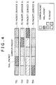
- each of the TSs TS1 to TS4 individually represent packets.
- the packets which configure each TS are classified into three different packets including a TS packet, a Null packet and a common packet.
- the TS packet contains data for proving various services, which are, in FIG. 4 , services 1 to 4, such as, for example, MPEG encode data.
- the Null packet contains data for adjustment which are transmitted in order to keep the amount information, which is to be outputted from the transmission side, fixed when the transmission side has no data to be transmitted.
- the Null packet prescribed in MPEG is a TS packet which has 0x47, 0x1F, 0xFF and 0x1F as four bytes at the top thereof, and all 1s are adopted for the bits of the payload.
- the common packet contains data which are common to a plurality of TSs.
- control information such as the SDT and the EIT described hereinabove corresponds to the common packet.
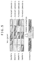
- the third packet from the left in the figure from among the five packets which configure each of the TSs TS1 to TS4 is a common packet. Since the common packets contain the same information, they are extracted as a common PLP as seen in FIG 5 .
- each of the TSs from which the common packet is extracted makes a sequence called Data PLP, that is, one of sequences Data PLP1 to Data PLP4.
- a Null packet is transmitted in the form of a signal (signaling) of 1 byte called DNP.
- the second and third packets from the left in the figure are Null packets, and in the case where two Null packets successively appear, they are replaced by a signal of 1 byte which has the value of 2 as seen in FIG. 6 .
- the value of the DNP corresponds to the number of successively appearing Null packets.
- each of the third and fifth packets from the left in FIG. 5 is a Null packet by itself, each of them is replaced by a signal of 1 byte having the value of 1 as seen in FIG. 6 .
- the transmission apparatus 2 produces four Data PLPs and one Common PLP from four TSs and carries out predetermined processes such as error correction and OFDM modulation for the produced signals. Then, the OFDM signal obtained by the predetermined processes is transmitted to the reception apparatus 1 through a predetermined transmission line.
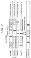
- the reception apparatus 1 receives an OFDM signal transmitted thereto from the transmission apparatus 2 through the predetermined transmission line, and the demodulation block 21 carries out predetermined processing such as OFDM demodulation for the OFDM signal to acquire sequences Data PLP1 to Data PLP4 and a Common PLP illustrated in FIG. 7 corresponding to the sequences Data PLP1 to Data PLP4 and the Common PLP illustrated in FIG. 6 , respectively. Then, for example, if the service 2 is selected by a user operation, then the sequence Data PLP2 from among the sequences Data PLP1 to Data PLP4 is extracted. The extracted sequence Data PLP2 and the Common PLP are subjected to predetermined processes such as error correction by the error correction block 22 and inputted to the output I/F 23.
- predetermined processing such as OFDM demodulation for the OFDM signal to acquire sequences Data PLP1 to Data PLP4 and a Common PLP illustrated in FIG. 7 corresponding to the sequences Data PLP1 to Data PLP4 and the Common PLP illustrated in FIG. 6
- sequence Data PLP2 and the Common PLP corresponding to the sequence Data PLP2 which are individually surrounded by thick frameworks in FIG. 7 are inputted to the output I/F 23.
- the output I/F 23 processes the sequence Data PLP2 and the Common PLP inputted thereto such that a Null packet included in the sequence Data PLP2 is replaced by the common packet included in the corresponding Common PLP. Consequently, the original TS TS2 similar to the TS TS2 illustrated in FIG. 4 is reconstructed as shown in FIG. 8 .
- FIG. 9 illustrates details of a desired Data PLP, particularly the sequence Data PLP2, and a Common PLP inputted to the output I/F 23 and a TS outputted from the output I/F 23.
- the Data PLP and the Common PLP inputted to the output I/F 23 have a DNP and information called ISSY (information such as the ISCR, BUFS, TTO and so forth) added thereto in a unit of a TS packet as described hereinabove.
- ISSY information such as the ISCR, BUFS, TTO and so forth
- the output I/F 23 uses such information as just mentioned obtained from the PLPs to detect a combination of two packets synchronized with each other from within the Data PLP and the Common PLP and adjusts the timings of the Data PLP and the Common PLP to synchronize them with each other.
- N_bits is the bit number per one packet, and, for example, 1504 (bits/packet) is substituted into N_bits.
- T is the unit of an elementary period, and, for example, in the case of the 8 MHz band, such a value as 7/64 us is substituted into T.
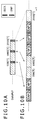
- FIGS. 10A and 10B illustrate an example of calculation of a TS rate executed by the readout rate calculation portion 33. It is to be noted that, in FIGS. 10A and 10B , the time advances from the left toward the right as indicated by an arrow mark on the bottom of FIG. 10B .
- TS packets and DNPs and ISCRs which are added to the individual TS packets are inputted as a Data PLP to the readout rate calculation portion 33.
- the DNP added to the first TS packet from the right in FIG. 10A indicates 3, and the ISCR indicates 3000 [T].
- the DNP of the second TS packet indicates 0 and the ISCR indicates 1000 [T]
- the DNP of the third TS packet indicates 2 and the ISCR indicates 500 [T].
- the Data PLP of FIG. 10A is converted into such a stream as seen in FIG 10B .
- the stream illustrated three Null packets denoted by NP in FIG 10B are placed next to the first TS packet and followed by the second and third TS packets, which are in turn followed by two Null packets.
- PacketRate ISCR_b - ISCR_a N_packets + ⁇ DNP
- FIG. 11 illustrates timings of writing into and reading out from the buffer 31.
- FIG. 11 a manner in which PLPs are successively accumulated into the buffer 31 is illustrated schematically.
- a manner in which Common PLPs are successively accumulated from above to below in FIG. 11 is illustrated in an upper side region of FIG. 11 while a manner in which Data PLPs are successively accumulated from below to above in FIG. 11 is illustrated in a lower side region of FIG. 11 .
- Common PLPs inputted to the output I/F 23 are successively stored into the buffer 31 under the control of the write control portion 32 such that five common packets (TS packets) illustrated in FIG. 11 are stored into a predetermined region on the upper side in FIG. 11 together with the ISSYs and the DNPs added thereto.
- TS packets common packets
- the inputted Data PLPs are successively stored into the buffer 31 under the control of the write control portion 32 such that five TS packets illustrated in FIG. 11 are stored into a predetermined region on the lower side in FIG. 11 together with the ISSYs and the DNPs added thereto.
- the Common PLPs and the Data PLPs are stored in such a manner as described above into the buffer 31. Then, the Common PLPs and the Data PLPs stored in the buffer 31 are read out under the control of the readout control portion 34.
- the TS packet at the top of the Data PLPs is read out later by 90000 [T] than the top of the P1 symbol using the value of the TTO, and the common packet at the top of the Common PLPs is read out later by 92000 [T] than the top of the P1 symbol, that is, after lapse of 2000 [T] after the TS packet at the top of the Data PLPs is read out.
- the readout control portion 34 reads out both of the Common PLPs and the Data PLPs from the buffer 31, it adjusts the output timings of the Common PLPs and the Data PLPs using the difference TTO diff. Then, if the readout control portion 34 detects a combination of a Common PLP and a Data PLP whose readout timings are synchronized with each other from the read out PLPs, then it replaces a Null packet placed in the Data PLP with the common packet of the Common PLP to reconstruct the original TS.
- Synchronization which uses a TTO (TTO diff ) which indicates a readout timing of a packet is carried out to reconstruct a TS in such a manner as described above.
- TTO diff TTO
- the synchronism between Common PLPs and Data PLPs is lost, resulting in the necessity for re-establishment of synchronism as described hereinabove.
- means for eliminating out-of-synchronism to re-establish synchronism particularly the TTO information retainer 51 and the address corrector 52 shown in FIG. 3 , are described with reference to FIGS. 12 and 13 .
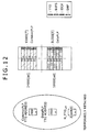
- FIG. 12 illustrates retention of TTO information upon writing of TS packets.
- FIG. 12 schematically illustrates a manner in which PLPs are successively accumulated into the buffer 31.
- TS packets ..., TS 38 , TS 39 , TS 40 , TS 41 , TS 42 , ... of Common PLPs are stored together with ISSys and DNPs added thereto in a predetermined region of the buffer 31 as seen in a region on the upper side in FIG. 12 .
- TS packets ..., TS 38 , TS 39 , TS 40 , TS 41 , TS 42 , ... of Data PLPs are stored in another predetermined region of the buffer 31 as seen in a region on the lower side in FIG. 12 .
- the TTO addresses and the differences H_TTO diff described hereinabove are retained into the TTO information retainer 51.
- the difference H_TTO diff represents by what number of packets the Common PLP and the Data PLP to which the TTO is added are displaced from each other in time.
- the packet rate P ts which is a period of time per one packet is 500 [T/packet]
- the TS packet (24000 [ad]) of the Common PLP is read out later by three packets than the TS packet (10000 [ad]) of the Data PLP.
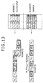
- FIG. 13 illustrates correction of an address using TTO information upon reading out of a TS packet. It is to be noted that, in FIG. 13 , the direction of time is a direction from the left toward the right.
- the address corrector 52 corrects the address so that the TS TS 40 is read out compulsorily in such a manner that the TTO address (24000 [ad]) of a Common Address is read out in place of the TS TS 41 of the Common PLP read out later by three packets after the TTO address (10000 [ad]) of the Data PLP is read out, that is, in such a manner that rewinding is carried out.
- TTO information obtained from TTOs added to the TS packets is retained and, upon readout of the TS packets, when TTO synchronism is lost, the retained TTO information is used to correct the read address, thereby re-establishing synchronism.
- a TTO added to a TS packet is basically placed only at the top of a T2 frame and the rate at which the TTO is included as an ISSY is not high
- the read address is corrected to re-establish synchronism
- the read address is immediately corrected to a correct read address which is not in an out-of-synchronism state.
- re-establishment of synchronism can be carried out rapidly.
- a Common PLP is "one PLP”
- a Data PLP is “the other PLP.”
- "one TTO address” is the TTO address of a Common PLP which is the one PLP
- the other TTO address is the TTO address of the Data PLP which is the other PLP.
- "one TTO address” is the TTO address of the Data PLP which is the one PLP
- "the other TTO address” is the TTO address of the Common PLP which is the other PLP.
- the write control portion 32 acquires TTO addresses and a difference H_TTO diff of a combination of a Common PLP and a Data PLP which are in TTO synchronism with each other upon writing of a TS packet into the buffer 31.
- the TTO information retainer 51 retains the TTO addresses and the difference H_TTO diff , that is, TTO information, acquired by the write control portion 32.
- the address corrector 52 discriminates whether or not the read address of the one PLP reaches the one TTO address retained in the TTO information retainer 51.
- step S13 If it is decided at step S13 that the two addresses coincide with each other and hence the read address of the one PLP reaches the one TTO address, then the address corrector 52 starts counting of the number of read out packets at step S14.
- the address corrector 52 repeats reading out of a TS packet thereby to successively count up the number of read out packets at step S14 until the number of read out packets reaches the difference H_TTO diff retained in the TTO information retainer 51 and a discrimination "Yes" is made at step S 15.
- the address corrector 52 compares the read address of the other PLP and the other TTO address retained in the TTO information retainer 51 with each other at step S16 and then discriminates whether or not the two addresses coincide with each other at step S17.
- the address corrector 52 replaces the read address of the other PLP with the other TTO address to correct the read address at step S18. Then, the readout control portion 34 reads out the TS packet of the other PLP accumulated in the buffer 31 in accordance with the read address replaced with the TTO address at step S19.
- step S17 if it is discriminated at step S17 that the read address of the other PLP and the other TTO address coincide with each other, then since the timing at which the TTO of the PLP is not displaced and TTO synchronism is maintained, the processing skips step S18 and advances directly to step S19. In this instance, at step S19, the readout control portion 34 reads out the TS packet of the other PLP accumulated in the buffer 31 in accordance with the read address not replaced with the TTO address.
- step S19 After reading out of the TS packet in accordance with the read address is carried out at step S19, if inputting of data is not completed as yet and the discrimination at step S20 is "No," then the process returns to step S11 to repeat the processes described above.
- TTO information of TTO addresses and differences H_TTO diff are retained by the TTO information retainer 51 and the address corrector 52 carries out, if the read address of the other PLP and the TTO address do not coincide with each other after lapse of the difference H_TTO diff after the read address of one PLP and the TTO address coincide with each other, correction of replacing the read address of the other PLP with the TTO address. Consequently, even where the read timing of a TS packet is displaced between a Common PLP and a Data PLP, the timings of them can be returned to correct timings to re-establish synchronism rapidly.
- FIG. 15 shows an example of a configuration of a first mode of a reception system to which the present invention is applied.
- the reception system includes an acquisition section 201, a transmission line decoding processing section 202 and an information source decoding processing section 203.
- the acquisition section 201 acquires an OFDM signal of the M-PLP system of DVB-T2 through a transmission line such as, for example, terrestrial digital broadcasting, satellite broadcasting, a CATV (Cable Television) network, the Internet or some other network not shown.
- the acquisition section 201 supplies the acquired OFDM signal to the transmission line decoding processing section 202.
- the acquisition section 201 is configured from a tuner, an STB or the like similarly to the acquisition section 12 shown in FIG. 2 .
- the OFDM signal is transmitted, for example, from a WEB server by multicast as in the case of IPTV (Internet Protocol Television)
- the acquisition section 201 is configured from a network I/F such as, for example, an NIC (Network Interface Card).
- the OFDM signal is broadcast, for example, from a broadcasting station through a ground wave, a satellite wave, a CATV network or the like, then, for example, a plurality of OFDM signals transmitted from a plurality of transmission apparatus through a plurality of transmission lines are received by the acquisition section 201. As a result, the plural OFDM signals are received as a combined single OFDM signal.
- the transmission line decoding processing section 202 carries out a transmission line decoding process including at least a process of decoding PLPs from an OFDM signal acquired by the acquisition section 201 through a transmission line. Then, the transmission line decoding processing section 202 supplies a signal obtained by the transmission line decoding process to the information source decoding processing section 203.
- an OFDM signal by the M-PLP system is defined by a plurality of Data PLPs configured from packets which remain when a packet common to all of a plurality of TSs is extracted from each of the TSs and a Common PLP configured from the common packet
- the transmission line decoding processing section 202 carries out, for example, a process of decoding PLPs (packet sequence) for the OFDM signal and outputs a resulting signal.
- the OFDM signal acquired by the acquisition section 201 through a transmission line is in a state distorted by an influence of a transmission line characteristic, and the transmission line decoding processing section 202 carries out a decoding process including, for example, transmission line estimation, channel estimation, phase estimation and so forth for such OFDM signal.
- the transmission line decoding process includes a process of correcting errors caused by the transmission line and so forth.
- error correction coding LDPC code, Reed Solomon coding and so forth are available.
- the information source decoding processing section 203 carries out an information source decoding process including at least a process of decompressing compressed information into original information for the signal for which the transmission line decoding process has been carried out.
- the OFDM signal acquired by the acquisition section 201 through a transmission line is sometimes in a state in which compression coding for compressing information in order to reduce the data amount of images, sound and so forth as information is applied.
- the information source decoding processing section 203 carries out an information source decoding process such as a process of decompressing the compressed information into original information and so forth for the signal to which the transmission line decoding process has been carried out.
- the information source decoding processing section 203 does not carry out the process of decompressing compressed information into original information.
- the decompression process may be, for example, MPEG decoding.
- the transmission line decoding process sometimes includes descrambling and so forth in addition to the decompression process.
- the acquisition section 201 acquires, through the transmission line, an OFDM signal according to the M-PLP system obtained by applying compression coding such as MPEG coding and further applying error correction coding for data, for example, of an image and sound.
- the acquisition section 201 supplies the acquired OFDM signal to the transmission line decoding processing section 202. It is to be noted that, at this time, the OFDM signal is acquired in a state distorted by an influence of a transmission line characteristic.
- the transmission line decoding processing section 202 carries out a process similar to that of the transmission line decoding processing section 13 shown in FIG. 2 as a transmission line decoding process for the OFDM signal from the acquisition section 201.
- the transmission line decoding processing section 202 supplies a signal obtained as a result of the transmission line decoding process to the information source decoding processing section 203.
- the information source decoding processing section 203 carries out a process similar to that of the decoder 14 shown in FIG. 2 as an information source decoding process for the signal from the transmission line decoding processing section 202.
- the information source decoding processing section 203 outputs an image or sound obtained as a result of the information source decoding process.
- Such a reception system of FIG. 15 as described above can be applied, for example, to a television tuner or the like which receives television broadcasting as digital broadcasting.
- the acquisition section 201, transmission line decoding processing section 202 and information source decoding processing section 203 can each be configured as a single independent apparatus or hardware apparatus such as an IC (Integrated Circuit) or a software module.
- the acquisition section 201, transmission line decoding processing section 202 and information source decoding processing section 203 can be configured in different manners.
- a set of the acquisition section 201 and the transmission line decoding processing section 202, a set of the transmission line decoding processing section 202 and the information source decoding processing section 203 or a set of the acquisition section 201, the transmission line decoding processing section 202, and information source decoding processing section 203 can be configured as a single independent apparatus.
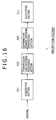
- FIG. 16 shows an example of a configuration of a second mode of the reception system to which the present invention is applied.
- the reception system shown in FIG. 16 includes common components to those of the reception system described hereinabove with reference to FIG. 15 , and overlapping description of the common components is omitted herein to avoid redundancy.
- the reception system shown is common to the reception system described hereinabove with reference to FIG. 15 in that it includes an acquisition section 201, a transmission line decoding processing section 202 and an information source decoding processing section 203 but is different from the reception system of FIG. 15 in that it additionally includes an outputting section 211.
- the outputting section 211 may be, for example, a display apparatus for displaying an image and/or a speaker for outputting sound, and outputs an image, sound or the like as a signal outputted from the information source decoding processing section 203. In other words, the outputting section 211 displays an image and/or outputs sound.
- Such a reception system of FIG. 16 as described above can be applied, for example, to a television set for receiving television broadcasting as digital broadcasting, a radio receiver for receiving radio broadcasting and so forth.
- FIG. 17 shows an example of a configuration of a third mode of the reception system to which the present invention is applied.
- the reception system shown in FIG. 17 includes common components to those of the reception system described hereinabove with reference to FIG. 15 , and overlapping description of the common components is omitted herein to avoid redundancy.
- the reception system shown is similar to that of FIG. 15 in that it includes an acquisition section 201 and a transmission line decoding processing section 202.
- reception system of FIG. 17 is different from that of FIG. 15 in that it does not include the information source decoding processing section 203 but includes a recording section 221.
- the recording section 221 records a signal outputted from the transmission line decoding processing section 202, for example, a TS packet of a TS of MPEG, in a recording (storage) medium such as an optical disk, a hard disk (magnetic disk) or a flash memory.
- a recording (storage) medium such as an optical disk, a hard disk (magnetic disk) or a flash memory.
- the reception system of FIG. 17 having such a configuration as described above can be applied to a recorder for recording a television broadcast or the like.
- the reception system of FIG. 17 may additionally include the information source decoding processing section 203 such that a signal after an information source decoding process is applied by the information source decoding processing section 203, that is, an image or sound obtained by decoding, can be recorded by the recording section 221.
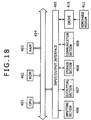
- FIG. 18 shows an example of a hardware configuration of a computer which executes the series of processes described hereinabove in accordance with a program.
- a central processing unit (CPU) 401, a read only memory (ROM) 402 and a random access memory (RAM) 403 are connected to one another by a bus 404.
- an input/output interface 405 is connected to the bus 404.
- An inputting section 406, an outputting section 407, a storage section 408 and a communication section 409 and a drive 410 are connected to the input/output interface 405.
- the inputting section 406 includes a keyboard, a mouse, a microphone and so forth.
- the outputting section 407 includes a display unit, a speaker and so forth.
- the storage section 408 includes a hard disk, a nonvolatile memory or the like.
- the communication section 409 includes a network interface or the like.
- the drive 410 drives a removable medium 411 such as a magnetic disk, an optical disk, a magneto-optical disk or a semiconductor memory.
- the CPU 401 loads a program stored, for example, in the storage section 408 into the RAM 403 through the input/output interface 405 and the bus 404 and executes the program to carry out the series of processes described above.
- the program to be executed by the computer can be recorded on and provided as a removable medium 411, for example, as a package medium or the like. Further, the program can be provided through a wire or wireless transmission medium such as a local area network, the Internet or a digital broadcast.
- the program can be installed into the storage section 408 through the input/output interface 405 by loading the removable medium 411 into the drive 410. Further, the program can be received by the communication section 409 through a wire or wireless transmission medium and installed into the storage section 408. Or, the program may be installed in advance in the ROM 402 or the storage section 408.
- the steps which describe the program recorded in or on a recording medium may be but need not necessarily be processed in a time series in the order as described, and include processes which are executed in parallel or individually without being processed in a time series.
- system is used to represent an entire apparatus composed of a plurality of devices or apparatus.
Landscapes
- Engineering & Computer Science (AREA)
- Signal Processing (AREA)
- Computer Networks & Wireless Communication (AREA)
- Power Engineering (AREA)
- Multimedia (AREA)
- Synchronisation In Digital Transmission Systems (AREA)
- Two-Way Televisions, Distribution Of Moving Picture Or The Like (AREA)
- Circuits Of Receivers In General (AREA)
- Compression Or Coding Systems Of Tv Signals (AREA)
- Detection And Prevention Of Errors In Transmission (AREA)
- Data Exchanges In Wide-Area Networks (AREA)
- Time-Division Multiplex Systems (AREA)
Applications Claiming Priority (1)
| Application Number | Priority Date | Filing Date | Title |
|---|---|---|---|
| JP2010000918A JP5476997B2 (ja) | 2010-01-06 | 2010-01-06 | 受信装置及び方法、プログラム、並びに受信システム |
Publications (3)
| Publication Number | Publication Date |
|---|---|
| EP2346221A2 true EP2346221A2 (de) | 2011-07-20 |
| EP2346221A3 EP2346221A3 (de) | 2011-09-07 |
| EP2346221B1 EP2346221B1 (de) | 2014-10-08 |
Family
ID=44115576
Family Applications (1)
| Application Number | Title | Priority Date | Filing Date |
|---|---|---|---|
| EP20100197237 Not-in-force EP2346221B1 (de) | 2010-01-06 | 2010-12-29 | Empfangsvorrichtung und -Verfahren, Programm und Empfangssystem |
Country Status (6)
| Country | Link |
|---|---|
| US (1) | US8929404B2 (de) |
| EP (1) | EP2346221B1 (de) |
| JP (1) | JP5476997B2 (de) |
| CN (1) | CN102118342B (de) |
| ES (1) | ES2521692T3 (de) |
| TW (1) | TWI469591B (de) |
Cited By (3)
| Publication number | Priority date | Publication date | Assignee | Title |
|---|---|---|---|---|
| EP3197175A4 (de) * | 2014-08-29 | 2018-02-21 | Sony Corporation | Empfangsvorrichtung und empfangsverfahren |
| EP3197174A4 (de) * | 2014-08-29 | 2018-05-23 | Sony Corporation | Empfangsvorrichtung und empfangsverfahren |
| EP3197171A4 (de) * | 2014-08-29 | 2018-05-23 | Sony Corporation | Empfangsvorrichtung und empfangsverfahren |
Families Citing this family (2)
| Publication number | Priority date | Publication date | Assignee | Title |
|---|---|---|---|---|
| JP2012222604A (ja) * | 2011-04-08 | 2012-11-12 | Sony Corp | データ読み出し装置、データ読み出し方法、並びにプログラム |
| CN106303580A (zh) * | 2015-07-08 | 2017-01-04 | 中国科学院上海高等研究院 | 一种ts流传输方法及系统 |
Citations (1)
| Publication number | Priority date | Publication date | Assignee | Title |
|---|---|---|---|---|
| JP2010000918A (ja) | 2008-06-20 | 2010-01-07 | Honda Motor Co Ltd | アクセルペダル反力制御装置 |
Family Cites Families (9)
| Publication number | Priority date | Publication date | Assignee | Title |
|---|---|---|---|---|
| JP3063824B2 (ja) * | 1996-10-29 | 2000-07-12 | 日本電気株式会社 | オーディオ・ビデオ同期再生装置 |
| US7095708B1 (en) * | 1999-06-23 | 2006-08-22 | Cingular Wireless Ii, Llc | Methods and apparatus for use in communicating voice and high speed data in a wireless communication system |
| JP5021114B2 (ja) * | 2000-09-07 | 2012-09-05 | ソニー株式会社 | 無線中継システム及び方法 |
| JP2002330433A (ja) * | 2001-04-27 | 2002-11-15 | Matsushita Electric Ind Co Ltd | 無線伝送システム |
| US7567746B2 (en) | 2003-03-19 | 2009-07-28 | Panasonic Corporation | Data processing device |
| JP4207639B2 (ja) * | 2003-04-11 | 2009-01-14 | パナソニック株式会社 | データ多重化方法、データ多重化装置、送信装置および受信装置 |
| KR100937430B1 (ko) * | 2008-01-25 | 2010-01-18 | 엘지전자 주식회사 | 신호 송수신 방법 및 신호 송수신 장치 |
| TWI471016B (zh) * | 2009-05-11 | 2015-01-21 | 晨星半導體股份有限公司 | 重建數位視訊資料流的方法與裝置 |
| JP5483081B2 (ja) * | 2010-01-06 | 2014-05-07 | ソニー株式会社 | 受信装置及び方法、プログラム、並びに受信システム |
-
2010
- 2010-01-06 JP JP2010000918A patent/JP5476997B2/ja not_active Expired - Fee Related
- 2010-12-29 CN CN201010611767.XA patent/CN102118342B/zh not_active Expired - Fee Related
- 2010-12-29 ES ES10197237.0T patent/ES2521692T3/es active Active
- 2010-12-29 EP EP20100197237 patent/EP2346221B1/de not_active Not-in-force
- 2010-12-29 TW TW99146692A patent/TWI469591B/zh not_active IP Right Cessation
- 2010-12-30 US US12/981,894 patent/US8929404B2/en active Active
Patent Citations (1)
| Publication number | Priority date | Publication date | Assignee | Title |
|---|---|---|---|---|
| JP2010000918A (ja) | 2008-06-20 | 2010-01-07 | Honda Motor Co Ltd | アクセルペダル反力制御装置 |
Cited By (3)
| Publication number | Priority date | Publication date | Assignee | Title |
|---|---|---|---|---|
| EP3197175A4 (de) * | 2014-08-29 | 2018-02-21 | Sony Corporation | Empfangsvorrichtung und empfangsverfahren |
| EP3197174A4 (de) * | 2014-08-29 | 2018-05-23 | Sony Corporation | Empfangsvorrichtung und empfangsverfahren |
| EP3197171A4 (de) * | 2014-08-29 | 2018-05-23 | Sony Corporation | Empfangsvorrichtung und empfangsverfahren |
Also Published As
| Publication number | Publication date |
|---|---|
| CN102118342A (zh) | 2011-07-06 |
| CN102118342B (zh) | 2014-04-02 |
| US20110164628A1 (en) | 2011-07-07 |
| ES2521692T3 (es) | 2014-11-13 |
| TW201145920A (en) | 2011-12-16 |
| EP2346221A3 (de) | 2011-09-07 |
| TWI469591B (zh) | 2015-01-11 |
| US8929404B2 (en) | 2015-01-06 |
| JP2011142420A (ja) | 2011-07-21 |
| EP2346221B1 (de) | 2014-10-08 |
| JP5476997B2 (ja) | 2014-04-23 |
Similar Documents
| Publication | Publication Date | Title |
|---|---|---|
| EP2355509B1 (de) | Empfangsvorrichtung und -verfahren, Programm und Empfangssystem | |
| US8520754B2 (en) | Reception apparatus and method, program and reception system | |
| EP2302848B1 (de) | Empfangsvorrichtung für Rekombination von Outputströmen in DVB-T2 | |
| US20070064588A1 (en) | Ofdm signal transmission method, transmission apparatus, and reception apparatus | |
| CN101715633A (zh) | 用于移动/手持通信系统的设备和方法 | |
| EP2346221B1 (de) | Empfangsvorrichtung und -Verfahren, Programm und Empfangssystem | |
| EP2696580B1 (de) | Datenabrufvorrichtung, datenabrufverfahren und programm | |
| US20100290459A1 (en) | Transmission apparatus and method for packet data of variable length, and receiving apparatus | |
| EP0775422B1 (de) | Vorrichtung zur formatierung von einem digitalen datenstrompacket für die übertragung von fernsehinformationen | |
| US9265007B2 (en) | Transmission device, transmission method, reception device, reception method, and program | |
| JP7692708B2 (ja) | 通信装置及び通信方法 |
Legal Events
| Date | Code | Title | Description |
|---|---|---|---|
| PUAI | Public reference made under article 153(3) epc to a published international application that has entered the european phase |
Free format text: ORIGINAL CODE: 0009012 |
|
| 17P | Request for examination filed |
Effective date: 20101229 |
|
| AK | Designated contracting states |
Kind code of ref document: A2 Designated state(s): AL AT BE BG CH CY CZ DE DK EE ES FI FR GB GR HR HU IE IS IT LI LT LU LV MC MK MT NL NO PL PT RO RS SE SI SK SM TR |
|
| AX | Request for extension of the european patent |
Extension state: BA ME |
|
| PUAL | Search report despatched |
Free format text: ORIGINAL CODE: 0009013 |
|
| AK | Designated contracting states |
Kind code of ref document: A3 Designated state(s): AL AT BE BG CH CY CZ DE DK EE ES FI FR GB GR HR HU IE IS IT LI LT LU LV MC MK MT NL NO PL PT RO RS SE SI SK SM TR |
|
| AX | Request for extension of the european patent |
Extension state: BA ME |
|
| RIC1 | Information provided on ipc code assigned before grant |
Ipc: H04L 27/26 20060101ALI20110729BHEP Ipc: H04N 7/24 20110101AFI20110729BHEP Ipc: H04J 3/06 20060101ALI20110729BHEP |
|
| REG | Reference to a national code |
Ref country code: DE Ref legal event code: R079 Ref document number: 602010019359 Country of ref document: DE Free format text: PREVIOUS MAIN CLASS: H04L0025020000 Ipc: H04N0021230000 |
|
| GRAP | Despatch of communication of intention to grant a patent |
Free format text: ORIGINAL CODE: EPIDOSNIGR1 |
|
| INTG | Intention to grant announced |
Effective date: 20140509 |
|
| RIC1 | Information provided on ipc code assigned before grant |
Ipc: H04N 21/43 20110101ALI20140429BHEP Ipc: H04N 21/23 20110101AFI20140429BHEP |
|
| GRAS | Grant fee paid |
Free format text: ORIGINAL CODE: EPIDOSNIGR3 |
|
| GRAA | (expected) grant |
Free format text: ORIGINAL CODE: 0009210 |
|
| AK | Designated contracting states |
Kind code of ref document: B1 Designated state(s): AL AT BE BG CH CY CZ DE DK EE ES FI FR GB GR HR HU IE IS IT LI LT LU LV MC MK MT NL NO PL PT RO RS SE SI SK SM TR |
|
| REG | Reference to a national code |
Ref country code: GB Ref legal event code: FG4D |
|
| REG | Reference to a national code |
Ref country code: AT Ref legal event code: REF Ref document number: 691165 Country of ref document: AT Kind code of ref document: T Effective date: 20141015 Ref country code: CH Ref legal event code: EP |
|
| REG | Reference to a national code |
Ref country code: IE Ref legal event code: FG4D |
|
| REG | Reference to a national code |
Ref country code: SE Ref legal event code: TRGR |
|
| REG | Reference to a national code |
Ref country code: ES Ref legal event code: FG2A Ref document number: 2521692 Country of ref document: ES Kind code of ref document: T3 Effective date: 20141113 |
|
| REG | Reference to a national code |
Ref country code: DE Ref legal event code: R096 Ref document number: 602010019359 Country of ref document: DE Effective date: 20141120 |
|
| REG | Reference to a national code |
Ref country code: NL Ref legal event code: T3 |
|
| REG | Reference to a national code |
Ref country code: LT Ref legal event code: MG4D |
|
| PG25 | Lapsed in a contracting state [announced via postgrant information from national office to epo] |
Ref country code: NO Free format text: LAPSE BECAUSE OF FAILURE TO SUBMIT A TRANSLATION OF THE DESCRIPTION OR TO PAY THE FEE WITHIN THE PRESCRIBED TIME-LIMIT Effective date: 20150108 Ref country code: LT Free format text: LAPSE BECAUSE OF FAILURE TO SUBMIT A TRANSLATION OF THE DESCRIPTION OR TO PAY THE FEE WITHIN THE PRESCRIBED TIME-LIMIT Effective date: 20141008 Ref country code: IS Free format text: LAPSE BECAUSE OF FAILURE TO SUBMIT A TRANSLATION OF THE DESCRIPTION OR TO PAY THE FEE WITHIN THE PRESCRIBED TIME-LIMIT Effective date: 20150208 Ref country code: PT Free format text: LAPSE BECAUSE OF FAILURE TO SUBMIT A TRANSLATION OF THE DESCRIPTION OR TO PAY THE FEE WITHIN THE PRESCRIBED TIME-LIMIT Effective date: 20150209 |
|
| PG25 | Lapsed in a contracting state [announced via postgrant information from national office to epo] |
Ref country code: HR Free format text: LAPSE BECAUSE OF FAILURE TO SUBMIT A TRANSLATION OF THE DESCRIPTION OR TO PAY THE FEE WITHIN THE PRESCRIBED TIME-LIMIT Effective date: 20141008 Ref country code: LV Free format text: LAPSE BECAUSE OF FAILURE TO SUBMIT A TRANSLATION OF THE DESCRIPTION OR TO PAY THE FEE WITHIN THE PRESCRIBED TIME-LIMIT Effective date: 20141008 Ref country code: CY Free format text: LAPSE BECAUSE OF FAILURE TO SUBMIT A TRANSLATION OF THE DESCRIPTION OR TO PAY THE FEE WITHIN THE PRESCRIBED TIME-LIMIT Effective date: 20141008 Ref country code: GR Free format text: LAPSE BECAUSE OF FAILURE TO SUBMIT A TRANSLATION OF THE DESCRIPTION OR TO PAY THE FEE WITHIN THE PRESCRIBED TIME-LIMIT Effective date: 20150109 Ref country code: PL Free format text: LAPSE BECAUSE OF FAILURE TO SUBMIT A TRANSLATION OF THE DESCRIPTION OR TO PAY THE FEE WITHIN THE PRESCRIBED TIME-LIMIT Effective date: 20141008 Ref country code: RS Free format text: LAPSE BECAUSE OF FAILURE TO SUBMIT A TRANSLATION OF THE DESCRIPTION OR TO PAY THE FEE WITHIN THE PRESCRIBED TIME-LIMIT Effective date: 20141008 |
|
| PG25 | Lapsed in a contracting state [announced via postgrant information from national office to epo] |
Ref country code: BE Free format text: LAPSE BECAUSE OF NON-PAYMENT OF DUE FEES Effective date: 20141231 |
|
| REG | Reference to a national code |
Ref country code: DE Ref legal event code: R097 Ref document number: 602010019359 Country of ref document: DE |
|
| PG25 | Lapsed in a contracting state [announced via postgrant information from national office to epo] |
Ref country code: CZ Free format text: LAPSE BECAUSE OF FAILURE TO SUBMIT A TRANSLATION OF THE DESCRIPTION OR TO PAY THE FEE WITHIN THE PRESCRIBED TIME-LIMIT Effective date: 20141008 Ref country code: EE Free format text: LAPSE BECAUSE OF FAILURE TO SUBMIT A TRANSLATION OF THE DESCRIPTION OR TO PAY THE FEE WITHIN THE PRESCRIBED TIME-LIMIT Effective date: 20141008 Ref country code: DK Free format text: LAPSE BECAUSE OF FAILURE TO SUBMIT A TRANSLATION OF THE DESCRIPTION OR TO PAY THE FEE WITHIN THE PRESCRIBED TIME-LIMIT Effective date: 20141008 Ref country code: RO Free format text: LAPSE BECAUSE OF FAILURE TO SUBMIT A TRANSLATION OF THE DESCRIPTION OR TO PAY THE FEE WITHIN THE PRESCRIBED TIME-LIMIT Effective date: 20141008 Ref country code: SK Free format text: LAPSE BECAUSE OF FAILURE TO SUBMIT A TRANSLATION OF THE DESCRIPTION OR TO PAY THE FEE WITHIN THE PRESCRIBED TIME-LIMIT Effective date: 20141008 Ref country code: LU Free format text: LAPSE BECAUSE OF FAILURE TO SUBMIT A TRANSLATION OF THE DESCRIPTION OR TO PAY THE FEE WITHIN THE PRESCRIBED TIME-LIMIT Effective date: 20141229 |
|
| REG | Reference to a national code |
Ref country code: CH Ref legal event code: PL |
|
| PLBE | No opposition filed within time limit |
Free format text: ORIGINAL CODE: 0009261 |
|
| STAA | Information on the status of an ep patent application or granted ep patent |
Free format text: STATUS: NO OPPOSITION FILED WITHIN TIME LIMIT |
|
| 26N | No opposition filed |
Effective date: 20150709 |
|
| REG | Reference to a national code |
Ref country code: IE Ref legal event code: MM4A |
|
| REG | Reference to a national code |
Ref country code: FR Ref legal event code: ST Effective date: 20150831 |
|
| PG25 | Lapsed in a contracting state [announced via postgrant information from national office to epo] |
Ref country code: LI Free format text: LAPSE BECAUSE OF NON-PAYMENT OF DUE FEES Effective date: 20141231 Ref country code: IE Free format text: LAPSE BECAUSE OF NON-PAYMENT OF DUE FEES Effective date: 20141229 Ref country code: CH Free format text: LAPSE BECAUSE OF NON-PAYMENT OF DUE FEES Effective date: 20141231 |
|
| PG25 | Lapsed in a contracting state [announced via postgrant information from national office to epo] |
Ref country code: FR Free format text: LAPSE BECAUSE OF NON-PAYMENT OF DUE FEES Effective date: 20141231 |
|
| PG25 | Lapsed in a contracting state [announced via postgrant information from national office to epo] |
Ref country code: SI Free format text: LAPSE BECAUSE OF FAILURE TO SUBMIT A TRANSLATION OF THE DESCRIPTION OR TO PAY THE FEE WITHIN THE PRESCRIBED TIME-LIMIT Effective date: 20141008 |
|
| PG25 | Lapsed in a contracting state [announced via postgrant information from national office to epo] |
Ref country code: SM Free format text: LAPSE BECAUSE OF FAILURE TO SUBMIT A TRANSLATION OF THE DESCRIPTION OR TO PAY THE FEE WITHIN THE PRESCRIBED TIME-LIMIT Effective date: 20141008 |
|
| PG25 | Lapsed in a contracting state [announced via postgrant information from national office to epo] |
Ref country code: MC Free format text: LAPSE BECAUSE OF FAILURE TO SUBMIT A TRANSLATION OF THE DESCRIPTION OR TO PAY THE FEE WITHIN THE PRESCRIBED TIME-LIMIT Effective date: 20141008 |
|
| PG25 | Lapsed in a contracting state [announced via postgrant information from national office to epo] |
Ref country code: BG Free format text: LAPSE BECAUSE OF FAILURE TO SUBMIT A TRANSLATION OF THE DESCRIPTION OR TO PAY THE FEE WITHIN THE PRESCRIBED TIME-LIMIT Effective date: 20141008 |
|
| PG25 | Lapsed in a contracting state [announced via postgrant information from national office to epo] |
Ref country code: HU Free format text: LAPSE BECAUSE OF FAILURE TO SUBMIT A TRANSLATION OF THE DESCRIPTION OR TO PAY THE FEE WITHIN THE PRESCRIBED TIME-LIMIT; INVALID AB INITIO Effective date: 20101229 Ref country code: TR Free format text: LAPSE BECAUSE OF FAILURE TO SUBMIT A TRANSLATION OF THE DESCRIPTION OR TO PAY THE FEE WITHIN THE PRESCRIBED TIME-LIMIT Effective date: 20141008 Ref country code: MT Free format text: LAPSE BECAUSE OF FAILURE TO SUBMIT A TRANSLATION OF THE DESCRIPTION OR TO PAY THE FEE WITHIN THE PRESCRIBED TIME-LIMIT Effective date: 20141008 |
|
| PG25 | Lapsed in a contracting state [announced via postgrant information from national office to epo] |
Ref country code: MK Free format text: LAPSE BECAUSE OF FAILURE TO SUBMIT A TRANSLATION OF THE DESCRIPTION OR TO PAY THE FEE WITHIN THE PRESCRIBED TIME-LIMIT Effective date: 20141008 |
|
| PG25 | Lapsed in a contracting state [announced via postgrant information from national office to epo] |
Ref country code: AL Free format text: LAPSE BECAUSE OF FAILURE TO SUBMIT A TRANSLATION OF THE DESCRIPTION OR TO PAY THE FEE WITHIN THE PRESCRIBED TIME-LIMIT Effective date: 20141008 |
|
| PGFP | Annual fee paid to national office [announced via postgrant information from national office to epo] |
Ref country code: GB Payment date: 20211221 Year of fee payment: 12 Ref country code: FI Payment date: 20211221 Year of fee payment: 12 Ref country code: SE Payment date: 20211222 Year of fee payment: 12 Ref country code: AT Payment date: 20211221 Year of fee payment: 12 |
|
| PGFP | Annual fee paid to national office [announced via postgrant information from national office to epo] |
Ref country code: IT Payment date: 20211220 Year of fee payment: 12 |
|
| PGFP | Annual fee paid to national office [announced via postgrant information from national office to epo] |
Ref country code: NL Payment date: 20211229 Year of fee payment: 12 |
|
| PGFP | Annual fee paid to national office [announced via postgrant information from national office to epo] |
Ref country code: ES Payment date: 20220110 Year of fee payment: 12 |
|
| PGFP | Annual fee paid to national office [announced via postgrant information from national office to epo] |
Ref country code: DE Payment date: 20220527 Year of fee payment: 13 |
|
| REG | Reference to a national code |
Ref country code: SE Ref legal event code: EUG |
|
| REG | Reference to a national code |
Ref country code: NL Ref legal event code: MM Effective date: 20230101 |
|
| REG | Reference to a national code |
Ref country code: AT Ref legal event code: MM01 Ref document number: 691165 Country of ref document: AT Kind code of ref document: T Effective date: 20221229 |
|
| GBPC | Gb: european patent ceased through non-payment of renewal fee |
Effective date: 20221229 |
|
| PG25 | Lapsed in a contracting state [announced via postgrant information from national office to epo] |
Ref country code: NL Free format text: LAPSE BECAUSE OF NON-PAYMENT OF DUE FEES Effective date: 20230101 |
|
| PG25 | Lapsed in a contracting state [announced via postgrant information from national office to epo] |
Ref country code: SE Free format text: LAPSE BECAUSE OF NON-PAYMENT OF DUE FEES Effective date: 20221230 Ref country code: GB Free format text: LAPSE BECAUSE OF NON-PAYMENT OF DUE FEES Effective date: 20221229 Ref country code: AT Free format text: LAPSE BECAUSE OF NON-PAYMENT OF DUE FEES Effective date: 20221229 |
|
| PG25 | Lapsed in a contracting state [announced via postgrant information from national office to epo] |
Ref country code: IT Free format text: LAPSE BECAUSE OF NON-PAYMENT OF DUE FEES Effective date: 20221229 |
|
| REG | Reference to a national code |
Ref country code: ES Ref legal event code: FD2A Effective date: 20240202 |
|
| PG25 | Lapsed in a contracting state [announced via postgrant information from national office to epo] |
Ref country code: ES Free format text: LAPSE BECAUSE OF NON-PAYMENT OF DUE FEES Effective date: 20221230 |
|
| PG25 | Lapsed in a contracting state [announced via postgrant information from national office to epo] |
Ref country code: FI Free format text: LAPSE BECAUSE OF NON-PAYMENT OF DUE FEES Effective date: 20221229 Ref country code: ES Free format text: LAPSE BECAUSE OF NON-PAYMENT OF DUE FEES Effective date: 20221230 |
|
| REG | Reference to a national code |
Ref country code: DE Ref legal event code: R119 Ref document number: 602010019359 Country of ref document: DE |
|
| PG25 | Lapsed in a contracting state [announced via postgrant information from national office to epo] |
Ref country code: DE Free format text: LAPSE BECAUSE OF NON-PAYMENT OF DUE FEES Effective date: 20240702 |
|
| PG25 | Lapsed in a contracting state [announced via postgrant information from national office to epo] |
Ref country code: DE Free format text: LAPSE BECAUSE OF NON-PAYMENT OF DUE FEES Effective date: 20240702 |