EP2346007A2 - Bill storage and bill handling apparatus - Google Patents
Bill storage and bill handling apparatus Download PDFInfo
- Publication number
- EP2346007A2 EP2346007A2 EP11150156A EP11150156A EP2346007A2 EP 2346007 A2 EP2346007 A2 EP 2346007A2 EP 11150156 A EP11150156 A EP 11150156A EP 11150156 A EP11150156 A EP 11150156A EP 2346007 A2 EP2346007 A2 EP 2346007A2
- Authority
- EP
- European Patent Office
- Prior art keywords
- bill
- bills
- receipt
- receipt portion
- bill storage
- Prior art date
- Legal status (The legal status is an assumption and is not a legal conclusion. Google has not performed a legal analysis and makes no representation as to the accuracy of the status listed.)
- Granted
Links
Images







Classifications
-
- G—PHYSICS
- G07—CHECKING-DEVICES
- G07D—HANDLING OF COINS OR VALUABLE PAPERS, e.g. TESTING, SORTING BY DENOMINATIONS, COUNTING, DISPENSING, CHANGING OR DEPOSITING
- G07D11/00—Devices accepting coins; Devices accepting, dispensing, sorting or counting valuable papers
- G07D11/10—Mechanical details
- G07D11/12—Containers for valuable papers
-
- G—PHYSICS
- G07—CHECKING-DEVICES
- G07F—COIN-FREED OR LIKE APPARATUS
- G07F19/00—Complete banking systems; Coded card-freed arrangements adapted for dispensing or receiving monies or the like and posting such transactions to existing accounts, e.g. automatic teller machines
- G07F19/20—Automatic teller machines [ATMs]
- G07F19/202—Depositing operations within ATMs
-
- B—PERFORMING OPERATIONS; TRANSPORTING
- B65—CONVEYING; PACKING; STORING; HANDLING THIN OR FILAMENTARY MATERIAL
- B65H—HANDLING THIN OR FILAMENTARY MATERIAL, e.g. SHEETS, WEBS, CABLES
- B65H83/00—Combinations of piling and depiling operations, e.g. performed simultaneously, of interest apart from the single operation of piling or depiling as such
- B65H83/02—Combinations of piling and depiling operations, e.g. performed simultaneously, of interest apart from the single operation of piling or depiling as such performed on the same pile or stack
- B65H83/025—Combinations of piling and depiling operations, e.g. performed simultaneously, of interest apart from the single operation of piling or depiling as such performed on the same pile or stack onto and from the same side of the pile or stack
Definitions
- the present invention relates to a bill handling apparatus installed in an automatic teller machine (ATM) mounted in, for example, a financial institution or the like, and a bill storage mounted in the bill handling apparatus.
- ATM automatic teller machine
- a bill handling apparatus is installed in an automatic teller machine used in a financial institution or the like.
- Such bill handling apparatus comprises a bill receipt/payment port, through which a user charges and takes out a bill, a bill discrimination unit, which discriminates a bill being received or paid, a temporary holding box, which temporarily receives a bill as received until an associated transaction is realized, a bill storage, which receives and holds a bill, and a bill conveyance path, through which a bill is conveyed to the respective units or boxes.
- the bill storage includes a reject box for receipt of rejected bill, which is discriminated by the bill discrimination unit not to meet a predetermined reference, a recycling box, in which bill for receipt and payment is received every denomination, and a loading box, which serves for replenishing of bill to the recycling box and for recovery of bill from the recycling box.
- a bill handling apparatus in which many bill storages are mounted to the extent possible.
- plural bill storages are arranged in a lower portion of the apparatus in alignment in a longitudinal direction of the apparatus, and a bill receipt/payment port, a bill discrimination unit, a temporary holding box, and other mechanism parts are arranged together in an upper portion of the apparatus.
- Denominations which a bill handling apparatus can handle, correspond to the number of the bill storages. That is, as the number of the bill storages is increased, it is possible to handle many denominations.
- the bill handling apparatus described in JP-A-8-221636 however, the bill handling apparatus is made large-sized in a longitudinal direction corresponding to the number of bill storages. Therefore, there has been demanded for a bill handling apparatus capable of corresponding to an increase in denomination while the apparatus is prevented from being made large-sized.
- JP-A-2008-152430 a bill storage provided therein with a plurality of receipt portions has been proposed as shown in JP-A-2008-152430 .
- JP-A-2008-152430 it becomes possible to handle a plurality of denominations only by one bill storage. Therefore, without the extension of bill storages, it becomes possible to provide a bill handling apparatus capable of corresponding to an increase in denomination.
- the bill storage disclosed in JP-A-2008-152430 comprises a bill inlet-outlet, through which a bill is taken out or received from the outside, a sorting gate, which switches connection of a conveyance path in order to distribute bills to destinations of conveyance, and a plurality of receipt portions including a taking-out and accumulating mechanism part (a feed roller, gate roller, etc.), which performs actions, in which bill is taken out and in which bill is accumulated.
- a taking-out and accumulating mechanism part a feed roller, gate roller, etc.
- an internal conveyance path through which a bill is conveyed in a vertical direction of the bill storage, and a sorting gate, which distributes bills to destinations of receipt, and the sorting gate and the taking-out and accumulating mechanism part are arranged adjacent to each other in this order from the bill inlet-outlet.
- a width of the bill storage, which has a plurality of receipt portions therein, in a longitudinal direction can be made as substantially small as that of a bill storage provided therein with a single receipt portion, which stores therein only one denomination.
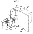
- Figs. 1 and 2 are perspective views showing an outline of an ATM as viewed from front and back sides thereof.
- a card and account-slip processing device 102 is provided in an upper, right interior of an ATM 101 to be communicated with a card slot 102a to transact a user's card to print and discharge a transaction detail slip.
- a passbook transaction device 103 is provided in an upper, left interior of the ATM 101 to be communicated with a passbook slot 103a to transact a user's passbook to print and discharge a transaction detail slip.
- a bill handling apparatus 1 is provided in a lower, right interior of the ATM 101 to handle bills.
- the bill handling apparatus 1 is communicated with a bill receipt/payment port shutter 20a, through which a user charges and takes out bills and bill receipt and payment transactions are processed.
- a coin handling apparatus 104 is provided in a lower, left interior of the ATM 101 to handle coins.
- the coin handling apparatus 104 is communicated with a coin receipt/payment port shutter 104a to process coin receipt and payment transactions.
- the ATM 101 may be one with which the coin handling apparatus 104 is not provided.
- a customer operation unit 105 to display and input contents of a transaction is provided on the front of the ATM 101.
- the bill handling apparatus 1 is provided with a tray 110 in a lower portion thereof as a portion, to which bill storages are mounted.
- Bill storages 70, 71a, 71b, 72a, 72b arranged in a row in a longitudinal direction of the ATM 101 are mounted detachably on the tray 110.
- Fig. 2 shows a construction, in which a door 200a on the rear is opened to permit the tray 110 to be pulled out
- a construction, in which a door 200b on the front is opened to permit the tray 110 to be pulled out, may apply.
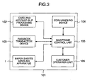
- Fig. 3 is a control block diagram showing a control relationship of the ATM 101.
- the ATM 101 comprises the card and account-slip processing device 102, the passbook transaction device 103, the bill receipt/payment machine 1, the coin handling apparatus 104, the customer operation unit 105, and a mainframe control unit 106.
- the card and account-slip processing device 102, the passbook transaction device 103, the bill receipt/payment machine 1, the coin handling apparatus 104, and the customer operation unit 105 perform necessary actions under the control of the mainframe control unit 106.
- Fig. 4 is a side view showing an internal construction of the bill handling apparatus 1.
- a bill receipt/payment port 20 is arranged on the front side (a side facing a user: an upper, right side in Fig. 4 ) of an upper portion of the bill handling apparatus 1.
- a bill discrimination unit 30, which discriminates bills being received or taken out is arranged centrally of the bill handling apparatus 1 and a temporary holding box 35, which temporarily receives bills as received until realization of an associated transaction is arranged on an upper portion of the back side (an opposite side to the front side: an upper, left side in Fig. 4 ) of the bill handling apparatus 1.
- a reject box 75 which stores bills not presented to receipt and payment transactions, or bills left behind a customer is arranged below the temporary holding box 35.
- the bill discrimination unit 30 can discriminate denomination and truth or falsehood of both bills conveyed toward the rear from the front and bills conveyed toward the front from the rear. That is, the bill discrimination unit 30 can discriminate denomination and truth or falsehood of bills conveyed two-way and can determine whether bills should be rejected or not.
- Bill storages 72b, 71b, 72a, 71a, which store bills, and a loading box 70, which performs loading and recovery of bills into the bill storages to function as a bill loading part are arranged from the front toward the rear in a lower portion of the bill handling apparatus 1.
- the bill storage 71 (71a and 71b) is one having a single receipt portion, which stores therein only one denomination.
- the bill storage 72 (72a and 72b) is one having two receipt portions therein.
- Fig. 5 is a control block diagram showing control relationship of the bill handling apparatus 1.
- a control unit 2 of the bill handling apparatus 1 is connected to the mainframe control unit 106 of the ATM 101 to control the bill handling apparatus 1 according to a command from the mainframe control unit 106 and detection of a state of the bill handling apparatus 1. Also, the control unit 2 forwards the state of the bill handling apparatus 1 to the mainframe control unit 106 at need.
- the bill handling apparatus 1 includes motors, solenoids, sensors, or the like for driving of the respective units (a conveyance path 10, the bill receipt/payment port 20, the bill discrimination unit 30, the temporary holding box 35, the loading box 70, the bill storages 71, 72, the reject box 75) and drivingly controls motors, solenoids, or the like while monitoring states of the units with the use of the sensors.
- the bill storage 72 having two receipt portions therein includes motors 61 a to 61 c serving as drive sources for conveyance, receiving and taking-out, or the like of bill and stepping motors 69b, 69c for actuation of the storage mechanisms, and the two receipt portions, respectively, can act independently.
- the bill handling apparatus 1 constructed in the manner described above can carry out bill receipt and payment transactions.
- the bill storages 71 and 72 are applied as recycling boxes for storage of bill for receipt and payment.
- the bill storages 71 and 72 may be applied as the reject boxes described above or loading boxes.
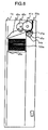
- Fig. 6 is a view showing the bill storage 71 having a single receipt portion therein.
- the bill storage 71 includes a receipt portion 700a, which includes a taking-out and accumulating mechanism part, a push plate 46a, a pinch roller 47a, and a bill inlet-outlet 50a, which is provided on an upper surface of the bill storage near to a front surface thereof to transfer bills to an outside conveyance path.
- a taking-out and accumulating mechanism part provided in the receipt portion 700a comprises a feed roller 41a, which rotates at a bill accumulating action and at a bill taking-out action to convey bills, a pick-up roller 42a, a gate roller 43a, which rotates at the bill accumulating action but does not rotate at the bill taking-out action, a brush roller 44a provided coaxially with the gate roller and having elastic members arranged radially, and a stack guide 45 a movable at the bill accumulating action and at the bill taking-out action.
- the bill storage 71 when the bill storage 71 functions only to accumulate bills, it may be constructed without the provision of the pick-up roller 42a. On the other hand, when the bill storage 71 functions only to take out bills, it may be constructed without the provision of the stack guide 45a.
- Fig. 7 is a view showing an action, in which bills are accumulated in the receipt portion 700a.
- Bills conveyed into the bill storage 71 through the bill inlet-outlet 50a are discharged into the receipt portion 700a as the feed roller 41a and the gate roller 43a rotate.
- the push plate 46a is moved by a driving force of a stepping motor (not shown).
- the push plate 46a is controlled in moving in a direction, in which bills as stored descend, so as to ensure a space in the receipt portion.
- the stack guide 45a rotates pivotally about a feed roller shaft 48a and so the stack guide 45a is moved slantwise.
- the stack guide 45a is moved slantwise whereby bills discharged into the receipt portion 700a move along a slope of the stack guide 45a.
- Fig. 8 is a view showing an action, in which bills are taken out of the receipt portion 700a.
- the push plate 46a is moved upward by the driving force of the stepping motor (not shown).
- the push plate 46a is moved upward and so a force of a spring (not shown) or the like has bills on the stack guide 45a pushed against the pick-up roller 42a with a predetermined push force.
- a force of a spring (not shown) or the like has bills on the stack guide 45a pushed against the pick-up roller 42a with a predetermined push force.
- the pick-up roller 42a rotates whereby a bill in contact with the pick-up roller 42a can be taken out of the receipt portion 700a.
- Bills taken out of the receipt portion 700a are forwarded by the feed roller 41 a, which rotates, and while the gate roller 43a, which does not rotate in a taking-out direction, prevents two sheets of bill from being forwarded at once, bills are conveyed one by one outside the bill storage through the pinch roller 47a from the bill inlet-outlet 50a. After a predetermined number of bills have been forwarded outside the bill storage, the feed roller 41 a is stopped.
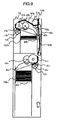
- Fig. 9 is a view showing the bill storage 72 provided therein with two receipt portions.
- the bill storage 72 comprises an upper receipt portion 700b and a lower receipt portion 700c, each of which includes a taking-out and accumulating mechanism part, push plates 46b, 46c, pinch rollers 47b, 47c, and a bill inlet-outlet 50b provided on an upper surface of the bill storage near to a front surface thereof for performing bill transferring to and from the outside conveyance path.
- the upper receipt portion 700b and the lower receipt portion 700c are arranged in a state of being stacked in this order from the neighborhood of the bill inlet-outlet 50b.
- the taking-out and accumulating mechanism parts provided in the respective receipt portions 700 (700b, 700c) comprise a feed roller 41 (41b, 41c), a pick-up roller 42 (42b, 42c), a gate roller 43 (43b, 43c), a brush roller 44 (44b, 44c), and a stack guide 45 (45b, 45c).
- the upper receipt portion 700b is constructed to permit bills to enter into the receipt portion from a back side (on the left in Fig. 9 ) of the bill storage 72, and the taking-out and accumulating mechanism part provided in the receipt portion 700b is provided on the back side of the bill storage 72.
- the bill inlet-outlet 50b is an inlet-outlet common to the upper receipt portion 700b and the lower receipt portion 700c, and a roller 51a is provided in a position adjacent to the inlet-outlet 50b to take bills into and outside the bill storage.
- the bill inlet-outlet 50b, the upper receipt portion 700b, and the lower receipt portion 700c are connected together by means of an internal conveyance path, through which bills can be bi-directionally conveyed.
- the conveyance path comprises an internal conveyance path 80a, through which bills are conveyed substantially in a horizontal direction (a longitudinal direction of the bill storage) and an internal conveyance path 80b, through which bills are conveyed substantially in a vertical direction (a direction perpendicular to the longitudinal direction of the bill storage).
- the internal conveyance path 80b is constructed such that a width of the conveyance path in the longitudinal direction is made a necessity minimum by an arrangement, in which a driven roller is pushed against a conveyor belt 65c arranged on one side to convey bills.
- a sorting gate 52a serving to distribute bills to the internal conveyance path 80a or the internal conveyance path 80b is arranged just below the roller 51 a.
- the bill storage 72 when the bill storage 72 only functions to accumulate bills, it may be constructed without the provision of the pick-up roller 42a (42b, 42c). On the other hand, when the bill storage 72 functions only to take out bills, it may be constructed without the provision of the stack guide 45 (45b, 45c). Also, when the bill storage 72 functions only to either accumulate or take out bills, the internal conveyance paths 80a and 80b may comprise a conveyance path, through which bills can be conveyed only one-way.
- a taking-out and accumulating mechanism part provided on the upper receipt portion 700b is arranged on the back side of the bill storage 72
- the bill inlet-outlet 50b, the sorting gate 52a, and the internal conveyance path 80b are arranged on the front side of the bill storage 72.
- the taking-out and accumulating mechanism part provided on the upper receipt portion 700b and the sorting gate 52a, respectively, are arranged in separate positions whereby it is made possible to decrease a space between the sorting gate 52a and the upper receipt portion 700b, thus leading to miniaturization of the bill storage 72.
- the taking-out and accumulating mechanism part provided on the upper receipt portion 700b is arranged on the back side of the bill storage 72 and the bill inlet-outlet 50b is arranged on the front side of the bill storage 72 whereby a space just below the sorting gate 52a can also be made use of as a portion of a space in the upper receipt portion 700b. Therefore, even a bill storage having the sorting gate 52a can make efficient use of a space in the bill storage to lead to miniaturization of the bill storage 72.
- the taking-out and accumulating mechanism part provided on the upper receipt portion 700b is arranged on the back side of the bill storage 72 and the space between the sorting gate 52a and the upper receipt portion 700b is made small, with the result that the upper receipt portion 700b is arranged in offset toward the front side of the bill storage 72 (on the right side in Fig. 9 ).
- the lower receipt portion 700c is arranged offset toward the back side of the bill storage 72 since its taking-out and accumulating mechanism part is provided on the front side of the bill storage 72.
- Fig. 10 is a view showing taking-out and accumulating operation parts, the roller 51a, and driving means of the conveyor belt 65 c, which are provided on the upper receipt portion 700b and on the lower receipt portion 700c.
- driving is transmitted to the feed roller 41 (41b, 41c) and the gate roller 43 (43b, 43c) through a driving transfer gear 62 (62a, 62b), a driving transfer gear 63 (63a, 63b), and a driving transfer gear 64 (64a, 64b) from a DC motor 61 (61a, 61b).
- driving is transmitted to the pick-up roller 42 through the driving transfer gear 62 (62a, 62b), the driving transfer gear 64 (64a, 64b), and a timing belt 65 (65a, 65b) from the DC motor 61 (61a, 61b). Further, driving is transmitted to the roller 51 a and the conveyor belt 65 c through a driving transfer gear 66 and a driving transfer gear 67 from a DC motor 61c.
- Fig. 11 is a view showing an action, in which bills are accumulated in the upper receipt portion 700b.
- Bills conveyed into the bill storage 72 through the bill inlet-outlet 50b are conveyed onto the internal conveyance path 80a by the roller 51a and the sorting gate 52a. Thereafter, bills are changed in a direction of conveyance by the feed roller 41b in a manner to have both sides thereof turned over and discharged into the upper receipt portion 700b.
- the push plate 46b is moved by a driving force of the stepping motor 69b (not shown).
- the push plate 46b is controlled in moving in a direction, in which bills as stored descend, so as to ensure a space in the receipt portion.
- the stack guide 45b rotates pivotally about a feed roller shaft 48b and so the stack guide 45b is moved slantwise.
- the stack guide 45b is moved slantwise whereby bills discharged into the upper receipt portion 700b move along a slope of the stack guide 45b.
- speed, at which bills are taken in by the feed roller 41b is preferably greater than or equal to speed, at which bills are conveyed along the internal conveyance path 80a, and is made substantially equal thereto in this embodiment.
- Fig. 12 is a view showing an action, in which bills are accumulated in the lower receipt portion 700c.
- Bills conveyed into the bill storage 72 through the bill inlet-outlet 50b are conveyed onto the internal conveyance path 80b by the roller 51a and the sorting gate 52a. Thereafter, bills are discharged into the lower receipt portion 700c by the feed roller 4 1 c.
- the push plate 46c is moved by a driving force of the stepping motor 69c (not shown).
- the push plate 46c is controlled in moving in a direction, in which bills as stored descend, so as to ensure a space in the receipt portion.
- the stack guide 45c rotates pivotally about a feed roller shaft 48c and so the stack guide 45c is moved slantwise.
- the stack guide 45c is moved slantwise whereby bills discharged into the lower receipt portion 700c move along a slope of the stack guide 45c.
- speed, at which bills are taken in by the feed roller 41c is preferably greater than or equal to speed, at which bills are conveyed along the internal conveyance path 80b, and is made substantially equal thereto in this embodiment.
- Fig. 13 is a view showing an action, in which bills are taken out of the upper receipt portion 700b.
- the push plate 46b is moved upward by a driving force of the stepping motor 69b (not shown).
- the push plate 46b is moved upward and so a force of a spring (not shown) or the like has bills on the stack guide 46b pushed against the pick-up roller 42b with a predetermined push force.
- the pick-up roller 42c causes the push plate 46c to descend to a position in no contact with bills in the lower receipt portion 700c.
- Bills taken out of the upper receipt portion 700b by the pick-up roller 42b are forwarded by the feed roller 41b, which rotates, and while the gate roller 43b, which does not rotate in a taking-out direction, prevents two bills from being forwarded at once, bills are forwarded onto the internal conveyance path 80a through the pinch roller 47b. Thereafter, bills are conveyed one by one outside the bill storage from the bill inlet-outlet 50b by the roller 51 a and the sorting gate 52a.
- the feed roller 41b is stopped. Then, after all bills on the internal conveyance path 80a are conveyed outside the bill storage, the internal conveyance path 80a and the roller 51 a are stopped.
- Fig. 14 is a view showing an action, in which bills are taken out of the lower receipt portion 700c.
- the push plate 46c is moved upward by a driving force of the stepping motor 69c.
- the push plate 46c is moved upward and so a force of a spring (not shown) or the like has bills on the push plate 46c pushed against the pick-up roller 42c with a predetermined push force.
- the pick-up roller 42b causes the push plate 46b to descend to a position in no contact with bills in the lower receipt portion 700b.
- Bills pushed against the pick-up roller 42c are forwarded by the feed roller 4 1 c, which rotates, and while the gate roller 43c, which does not rotate in a taking-out direction, prevents two bills from being forwarded at once, bills are forwarded onto the conveyance path 80b. Thereafter, bills are conveyed one by one outside the bill storage from the bill inlet-outlet 50b by the roller 51a and the sorting gate 52a.
- the feed roller 41c is stopped. Then, after all bills on the conveyance path 80b are conveyed outside the bill storage, the conveyance path 80b and the roller 51a are stopped.
- the respective bill storages 71, 72 in the bill handling apparatus constructed in a manner described above are constructed to be common to each other in outside dimension, in a position of the bill inlet-outlet (50a, 50b), in the shape of the bill inlet-outlet, and so on. Thereby, it is possible to provide interchangeability to the respective bill storages 71, 72, so that it is possible to freely change the combination of the bill storages 71, 72 to mount the same on the tray 110 according to the situation of application in respective countries.
- bills circulated in Japan include four kinds of bill, that is, 10,000-yen note, 5,000-yen note, 2,000-yen note, and 1,000-yen note
- application can be made such that 10,000-yen notes and 1,000-yen notes, which are large in amount of circulation, can be stored in the bill storage 71 provided therein with a single receipt portion and 5,000-yen notes and 2,000-yen notes, which are small in amount of circulation, can be stored together in the bill storage 72 provided therein with two receipt portions.
- Fig. 15 is a perspective view showing an appearance of the bill storage 72.
- the bill storage 72 is provided with an upper door 81, through which bills are charged into and taken out of the upper receipt portion 700b, and a lower door 82, through which bills are charged into and taken out of the bill receipt portion 700c.
- the upper door 81 and the lower door 82 which are provided on the back side of the bill storage, can be opened and closed independently of each other and enable bills to be charged into and taken out of the upper receipt portion 700b and the lower receipt portion 700c as need arises.
- the upper door 81 is constructed to turn about a rotating shaft 83 as a fulcrum to be opened and closed (referred below to as vertical opening), and the lower door 82 is constructed to turn about a rotating shaft 84, which is arranged at a corner of the bill storage 72, as a fulcrum to be opened and closed (referred below to as horizontal opening). That is, the upper door 81 and the lower door 82 are different from each other in directions of opening and closing.
- the feed roller 41b is desirably left in the bill storage 72 irrespective of opening and closing of the upper door 81. Also, in the case where the gate roller 43b is disposed in the interior of the bill storage 72, it is difficult for a user to take in and out bills, so that it is desirable to interlockingly retreat the gate roller 43b and the upper door 81.
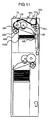
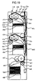
- Figs. 16 and 17 are views showing the bill storage 72 when the upper door 81 is opened and when the upper door 81 is closed. At this time, the gate roller 43b, the pinch roller 47b, and a conveyance guide 90 to the upper receipt portion 700b interlock with the upper door 81 to retreat, so that it is easy for a user to take in and out bills in loading and taking out bills.
- a shaft positioning plate 91 is arranged in two locations inside the bill storage 72 and outside the internal conveyance path 80a of bill.
- the shaft positioning plate 91 precisely fixes a center distance between the feed roller shaft 48b and the gate roller shaft 49b.
- a contact area between the shaft positioning plate 91 and the gate roller shaft 49b is made a necessity minimum to an extent capable of interposition of the gate roller shaft 49b.
- the taking-out and accumulating mechanism part (41 c to 45c) provided in the lower receipt portion 700c is arranged substantially vertically downwardly of the bill inlet-outlet 50b, but it may be arranged substantially vertically downwardly of the taking-out and accumulating mechanism part (41b to 45b) provided in the upper receipt portion 700b as shown in Fig. 18 .
- the bill storage may have three receipt portions therein.
- a taking-out and accumulating mechanism part (41d to 45d (41e to 45e)) provided in an upper receipt portion 700d (an intermediate receipt portion 700e) is arranged on a side horizontally opposed to a bill inlet-outlet 50c, a sorting gate 52b (52c), and an internal conveyance path 80c (80d) with an upper receipt portion 700d (an intermediate receipt portion 700e) therebetween.
- a width of a bill storage, which has a plurality of receipt portions therein, in a longitudinal direction can be made as substantially small as that of a bill storage provided therein with a single receipt portion, which stores therein only one denomination. Also, by optionally selecting a bill storage, which has a plurality of receipt portions therein, or a bill storage, which has a single receipt portion therein, to mount the same on the tray 110, it is possible to provide a bill handling apparatus, which can flexibly conform to the situation of application in respective countries.
Landscapes
- Physics & Mathematics (AREA)
- General Physics & Mathematics (AREA)
- Business, Economics & Management (AREA)
- Accounting & Taxation (AREA)
- Finance (AREA)
- Pile Receivers (AREA)
- Sheets, Magazines, And Separation Thereof (AREA)
- Registering Or Overturning Sheets (AREA)
- Separation, Sorting, Adjustment, Or Bending Of Sheets To Be Conveyed (AREA)
Abstract
Description
- The present application claims priority from Japanese application
JP 2010-004520 filed on January 13, 2010 - The present invention relates to a bill handling apparatus installed in an automatic teller machine (ATM) mounted in, for example, a financial institution or the like, and a bill storage mounted in the bill handling apparatus.
- Conventionally, a bill handling apparatus is installed in an automatic teller machine used in a financial institution or the like. Such bill handling apparatus comprises a bill receipt/payment port, through which a user charges and takes out a bill, a bill discrimination unit, which discriminates a bill being received or paid, a temporary holding box, which temporarily receives a bill as received until an associated transaction is realized, a bill storage, which receives and holds a bill, and a bill conveyance path, through which a bill is conveyed to the respective units or boxes.
- The bill storage includes a reject box for receipt of rejected bill, which is discriminated by the bill discrimination unit not to meet a predetermined reference, a recycling box, in which bill for receipt and payment is received every denomination, and a loading box, which serves for replenishing of bill to the recycling box and for recovery of bill from the recycling box.
- Recently, as cash handled in an ATM is increased in denomination, there is proposed a bill handling apparatus, in which many bill storages are mounted to the extent possible. In a bill handling apparatus described in
JP-A-8-221636 - Denominations, which a bill handling apparatus can handle, correspond to the number of the bill storages. That is, as the number of the bill storages is increased, it is possible to handle many denominations. In case of the bill handling apparatus described in
JP-A-8-221636 - Meeting the demand described above, a bill storage provided therein with a plurality of receipt portions has been proposed as shown in
JP-A-2008-152430 JP-A-2008-152430 - The bill storage disclosed in
JP-A-2008-152430 - That is, since the mechanism part is concentrated in the vicinity between the bill inlet-outlet and the receipt portions, the storage is increased in dimension in a longitudinal direction. Therefore, there has been a demand for realization of a bill storage provided therein with a plurality of receipt portions while the apparatus is prevented from becoming large in size.
- Meeting the demand described above, it is an object of the invention to miniaturize a bill storage provided therein with a plurality of receipt portions. Concretely, while a taking-out and accumulating mechanism part provided in a receipt portion nearest to a bill inlet-outlet and a sorting gate for switching of conveyance of bill are conventionally arranged adjacent to each other, the taking-out and accumulating mechanism part and the sorting gate are arranged separately.
- According to the invention, it becomes possible to decrease a space between the sorting gate and the receipt portions. Therefore, a width of the bill storage, which has a plurality of receipt portions therein, in a longitudinal direction can be made as substantially small as that of a bill storage provided therein with a single receipt portion, which stores therein only one denomination.
- Also, it becomes possible to optionally select and mount a bill storage, which has a plurality of receipt portions therein, or a bill storage, which has a single receipt portion therein, without a change in construction of the bill handling apparatus. Therefore, it becomes possible to provide a bill handling apparatus capable of flexibly accommodating an increase in denomination.
- Other objects, features and advantages of the invention will become apparent from the following description of the embodiments of the invention taken in conjunction with the accompanying drawings.
-
-
Fig. 1 is a perspective view showing an outline of an ATM as viewed from a front side thereof; -
Fig. 2 is a perspective view showing the outline of the ATM as viewed from a back side thereof; -
Fig. 3 is a control block diagram showing the control relationship of the ATM; -
Fig. 4 is a view showing an internal construction of a bill handling apparatus; -
Fig. 5 is a control block diagram showing the control relationship of the bill handling apparatus; -
Fig. 6 is a side view showing a bill storage having a single receipt portion therein; -
Fig. 7 is a side view showing an action, in which bills are accumulated in the receipt portion; -
Fig. 8 is a side view showing an action, in which bills are taken out of the receipt portion; -
Fig. 9 is a side view showing a bill storage having two receipt portions therein; -
Fig. 10 is a side view showing a driving means of the bill storage having two receipt portions therein; -
Fig. 11 is a side view showing an action, in which bills are accumulated in an upper receipt portion; -
Fig. 12 is a side view showing an action, in which bills are accumulated in a lower receipt portion; -
Fig. 13 is a side view showing an action, in which bills are taken out of the upper receipt portion; -
Fig. 14 is a side view showing an action, in which bills are taken out of the lower receipt portion; -
Fig. 15 is a perspective view showing an outline of a bill storage having two receipt portions therein; -
Fig. 16 is a side view showing the bill storage when an upper door is opened; -
Fig. 17 is a side view showing the bill storage when the upper door is closed; -
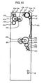
Fig. 18 is a side view showing a bill storage having two receipt portions therein (another embodiment); and -
Fig. 19 is a side view showing a bill storage having three receipt portions therein. - An embodiment of the invention will be described with reference to the drawings.
-
Figs. 1 and2 , respectively, are perspective views showing an outline of an ATM as viewed from front and back sides thereof. - A card and account-
slip processing device 102 is provided in an upper, right interior of anATM 101 to be communicated with acard slot 102a to transact a user's card to print and discharge a transaction detail slip. Apassbook transaction device 103 is provided in an upper, left interior of theATM 101 to be communicated with apassbook slot 103a to transact a user's passbook to print and discharge a transaction detail slip. - Also, a
bill handling apparatus 1 is provided in a lower, right interior of theATM 101 to handle bills. Thebill handling apparatus 1 is communicated with a bill receipt/payment port shutter 20a, through which a user charges and takes out bills and bill receipt and payment transactions are processed. Acoin handling apparatus 104 is provided in a lower, left interior of theATM 101 to handle coins. Thecoin handling apparatus 104 is communicated with a coin receipt/payment port shutter 104a to process coin receipt and payment transactions. In addition, the ATM 101 may be one with which the coin handlingapparatus 104 is not provided. - Also, a
customer operation unit 105 to display and input contents of a transaction is provided on the front of theATM 101. - The
bill handling apparatus 1 is provided with atray 110 in a lower portion thereof as a portion, to which bill storages are mounted.Bill storages ATM 101 are mounted detachably on thetray 110. In addition, whileFig. 2 shows a construction, in which adoor 200a on the rear is opened to permit thetray 110 to be pulled out, a construction, in which adoor 200b on the front is opened to permit thetray 110 to be pulled out, may apply. -
Fig. 3 is a control block diagram showing a control relationship of theATM 101. - The
ATM 101 comprises the card and account-slip processing device 102, thepassbook transaction device 103, the bill receipt/payment machine 1, thecoin handling apparatus 104, thecustomer operation unit 105, and amainframe control unit 106. The card and account-slip processing device 102, thepassbook transaction device 103, the bill receipt/payment machine 1, thecoin handling apparatus 104, and thecustomer operation unit 105 perform necessary actions under the control of themainframe control unit 106. -
Fig. 4 is a side view showing an internal construction of thebill handling apparatus 1. - A bill receipt/
payment port 20 is arranged on the front side (a side facing a user: an upper, right side inFig. 4 ) of an upper portion of thebill handling apparatus 1. Also, abill discrimination unit 30, which discriminates bills being received or taken out is arranged centrally of thebill handling apparatus 1 and atemporary holding box 35, which temporarily receives bills as received until realization of an associated transaction is arranged on an upper portion of the back side (an opposite side to the front side: an upper, left side inFig. 4 ) of thebill handling apparatus 1. Areject box 75, which stores bills not presented to receipt and payment transactions, or bills left behind a customer is arranged below thetemporary holding box 35. These mechanisms are connected together by two-way conveyance paths 10a to 10f, through which bills are conveyed two-way, and one-way conveyance paths - Here, the
bill discrimination unit 30 can discriminate denomination and truth or falsehood of both bills conveyed toward the rear from the front and bills conveyed toward the front from the rear. That is, thebill discrimination unit 30 can discriminate denomination and truth or falsehood of bills conveyed two-way and can determine whether bills should be rejected or not. - Bill storages 72b, 71b, 72a, 71a, which store bills, and a
loading box 70, which performs loading and recovery of bills into the bill storages to function as a bill loading part are arranged from the front toward the rear in a lower portion of thebill handling apparatus 1. The bill storage 71 (71a and 71b) is one having a single receipt portion, which stores therein only one denomination. On the other hand, the bill storage 72 (72a and 72b) is one having two receipt portions therein. -
Fig. 5 is a control block diagram showing control relationship of thebill handling apparatus 1. - A
control unit 2 of thebill handling apparatus 1 is connected to themainframe control unit 106 of theATM 101 to control thebill handling apparatus 1 according to a command from themainframe control unit 106 and detection of a state of thebill handling apparatus 1. Also, thecontrol unit 2 forwards the state of thebill handling apparatus 1 to themainframe control unit 106 at need. - The
bill handling apparatus 1 includes motors, solenoids, sensors, or the like for driving of the respective units (aconveyance path 10, the bill receipt/payment port 20, thebill discrimination unit 30, thetemporary holding box 35, theloading box 70, the bill storages 71, 72, the reject box 75) and drivingly controls motors, solenoids, or the like while monitoring states of the units with the use of the sensors. In particular, thebill storage 72 having two receipt portions therein includesmotors 61 a to 61 c serving as drive sources for conveyance, receiving and taking-out, or the like of bill and steppingmotors - The
bill handling apparatus 1 constructed in the manner described above can carry out bill receipt and payment transactions. - Hereinafter, a case where the bill storages 71 and 72 are applied as recycling boxes for storage of bill for receipt and payment will be described. In addition, the bill storages 71 and 72 may be applied as the reject boxes described above or loading boxes.
- First, actions of the
bill storage 71 having a single receipt portion therein will be described. -
Fig. 6 is a view showing thebill storage 71 having a single receipt portion therein. Thebill storage 71 includes areceipt portion 700a, which includes a taking-out and accumulating mechanism part, apush plate 46a, apinch roller 47a, and a bill inlet-outlet 50a, which is provided on an upper surface of the bill storage near to a front surface thereof to transfer bills to an outside conveyance path. - A taking-out and accumulating mechanism part provided in the
receipt portion 700a comprises afeed roller 41a, which rotates at a bill accumulating action and at a bill taking-out action to convey bills, a pick-uproller 42a, agate roller 43a, which rotates at the bill accumulating action but does not rotate at the bill taking-out action, abrush roller 44a provided coaxially with the gate roller and having elastic members arranged radially, and astack guide 45 a movable at the bill accumulating action and at the bill taking-out action. - In addition, when the
bill storage 71 functions only to accumulate bills, it may be constructed without the provision of the pick-uproller 42a. On the other hand, when thebill storage 71 functions only to take out bills, it may be constructed without the provision of thestack guide 45a. -
Fig. 7 is a view showing an action, in which bills are accumulated in thereceipt portion 700a. - Bills conveyed into the
bill storage 71 through the bill inlet-outlet 50a are discharged into thereceipt portion 700a as thefeed roller 41a and thegate roller 43a rotate. - Here, before bills are discharged into the
receipt portion 700a, thepush plate 46a is moved by a driving force of a stepping motor (not shown). Thepush plate 46a is controlled in moving in a direction, in which bills as stored descend, so as to ensure a space in the receipt portion. Subsequently, thestack guide 45a rotates pivotally about afeed roller shaft 48a and so thestack guide 45a is moved slantwise. Thestack guide 45a is moved slantwise whereby bills discharged into thereceipt portion 700a move along a slope of thestack guide 45a. -
Fig. 8 is a view showing an action, in which bills are taken out of thereceipt portion 700a. - The
push plate 46a is moved upward by the driving force of the stepping motor (not shown). Thepush plate 46a is moved upward and so a force of a spring (not shown) or the like has bills on thestack guide 45a pushed against the pick-uproller 42a with a predetermined push force. In addition, while the case where thepush plate 46a pushes bills has been described, a construction will do, in which the pick-uproller 42a pushes bills. - As described above, in a state, in which a push force acts between the pick-up
roller 42a and bills, the pick-uproller 42a rotates whereby a bill in contact with the pick-uproller 42a can be taken out of thereceipt portion 700a. Bills taken out of thereceipt portion 700a are forwarded by thefeed roller 41 a, which rotates, and while thegate roller 43a, which does not rotate in a taking-out direction, prevents two sheets of bill from being forwarded at once, bills are conveyed one by one outside the bill storage through thepinch roller 47a from the bill inlet-outlet 50a. After a predetermined number of bills have been forwarded outside the bill storage, thefeed roller 41 a is stopped. - Subsequently, actions of the
bill storage 72 provided therein with two receipt portions will be described. -
Fig. 9 is a view showing thebill storage 72 provided therein with two receipt portions. Thebill storage 72 comprises anupper receipt portion 700b and alower receipt portion 700c, each of which includes a taking-out and accumulating mechanism part, pushplates pinch rollers outlet 50b provided on an upper surface of the bill storage near to a front surface thereof for performing bill transferring to and from the outside conveyance path. Theupper receipt portion 700b and thelower receipt portion 700c are arranged in a state of being stacked in this order from the neighborhood of the bill inlet-outlet 50b. - Like the taking-out and accumulating mechanism part provided in the
receipt portion 700a of thebill storage 71 provided therein with a single receipt portion, the taking-out and accumulating mechanism parts provided in the respective receipt portions 700 (700b, 700c) comprise a feed roller 41 (41b, 41c), a pick-up roller 42 (42b, 42c), a gate roller 43 (43b, 43c), a brush roller 44 (44b, 44c), and a stack guide 45 (45b, 45c). In particular, theupper receipt portion 700b is constructed to permit bills to enter into the receipt portion from a back side (on the left inFig. 9 ) of thebill storage 72, and the taking-out and accumulating mechanism part provided in thereceipt portion 700b is provided on the back side of thebill storage 72. - The bill inlet-
outlet 50b is an inlet-outlet common to theupper receipt portion 700b and thelower receipt portion 700c, and aroller 51a is provided in a position adjacent to the inlet-outlet 50b to take bills into and outside the bill storage. By arranging theroller 51a, thefeed roller 41b, and thegate roller 42b substantially in the same level, theupper receipt portion 700b is prevented from being decreased in volume. - The bill inlet-
outlet 50b, theupper receipt portion 700b, and thelower receipt portion 700c are connected together by means of an internal conveyance path, through which bills can be bi-directionally conveyed. Concretely, the conveyance path comprises aninternal conveyance path 80a, through which bills are conveyed substantially in a horizontal direction (a longitudinal direction of the bill storage) and aninternal conveyance path 80b, through which bills are conveyed substantially in a vertical direction (a direction perpendicular to the longitudinal direction of the bill storage). Theinternal conveyance path 80b is constructed such that a width of the conveyance path in the longitudinal direction is made a necessity minimum by an arrangement, in which a driven roller is pushed against aconveyor belt 65c arranged on one side to convey bills. Also, a sortinggate 52a serving to distribute bills to theinternal conveyance path 80a or theinternal conveyance path 80b is arranged just below theroller 51 a. - In addition, when the
bill storage 72 only functions to accumulate bills, it may be constructed without the provision of the pick-uproller 42a (42b, 42c). On the other hand, when thebill storage 72 functions only to take out bills, it may be constructed without the provision of the stack guide 45 (45b, 45c). Also, when thebill storage 72 functions only to either accumulate or take out bills, theinternal conveyance paths - As shown in
Fig. 9 , while a taking-out and accumulating mechanism part provided on theupper receipt portion 700b is arranged on the back side of thebill storage 72, the bill inlet-outlet 50b, the sortinggate 52a, and theinternal conveyance path 80b are arranged on the front side of thebill storage 72. The taking-out and accumulating mechanism part provided on theupper receipt portion 700b and the sortinggate 52a, respectively, are arranged in separate positions whereby it is made possible to decrease a space between the sortinggate 52a and theupper receipt portion 700b, thus leading to miniaturization of thebill storage 72. Also, the taking-out and accumulating mechanism part provided on theupper receipt portion 700b is arranged on the back side of thebill storage 72 and the bill inlet-outlet 50b is arranged on the front side of thebill storage 72 whereby a space just below the sortinggate 52a can also be made use of as a portion of a space in theupper receipt portion 700b. Therefore, even a bill storage having the sortinggate 52a can make efficient use of a space in the bill storage to lead to miniaturization of thebill storage 72. - In addition, as described above, the taking-out and accumulating mechanism part provided on the
upper receipt portion 700b is arranged on the back side of thebill storage 72 and the space between the sortinggate 52a and theupper receipt portion 700b is made small, with the result that theupper receipt portion 700b is arranged in offset toward the front side of the bill storage 72 (on the right side inFig. 9 ). On the other hand, thelower receipt portion 700c is arranged offset toward the back side of thebill storage 72 since its taking-out and accumulating mechanism part is provided on the front side of thebill storage 72. -
Fig. 10 is a view showing taking-out and accumulating operation parts, theroller 51a, and driving means of theconveyor belt 65 c, which are provided on theupper receipt portion 700b and on thelower receipt portion 700c. Out of the taking-out and accumulating operation parts, driving is transmitted to the feed roller 41 (41b, 41c) and the gate roller 43 (43b, 43c) through a driving transfer gear 62 (62a, 62b), a driving transfer gear 63 (63a, 63b), and a driving transfer gear 64 (64a, 64b) from a DC motor 61 (61a, 61b). Also, driving is transmitted to the pick-up roller 42 through the driving transfer gear 62 (62a, 62b), the driving transfer gear 64 (64a, 64b), and a timing belt 65 (65a, 65b) from the DC motor 61 (61a, 61b). Further, driving is transmitted to theroller 51 a and theconveyor belt 65 c through a drivingtransfer gear 66 and a drivingtransfer gear 67 from aDC motor 61c. - In addition, supplying of electricity to the DC motor and sending /receiving of electric signals by sensors (not shown) are conducted through a
connector 68 provided on a lower portion of thebill storage 72. -
Fig. 11 is a view showing an action, in which bills are accumulated in theupper receipt portion 700b. - Bills conveyed into the
bill storage 72 through the bill inlet-outlet 50b are conveyed onto theinternal conveyance path 80a by theroller 51a and the sortinggate 52a. Thereafter, bills are changed in a direction of conveyance by thefeed roller 41b in a manner to have both sides thereof turned over and discharged into theupper receipt portion 700b. - Here, before bills are discharged into the
upper receipt portion 700b, thepush plate 46b is moved by a driving force of the steppingmotor 69b (not shown). Thepush plate 46b is controlled in moving in a direction, in which bills as stored descend, so as to ensure a space in the receipt portion. Subsequently, thestack guide 45b rotates pivotally about afeed roller shaft 48b and so thestack guide 45b is moved slantwise. Thestack guide 45b is moved slantwise whereby bills discharged into theupper receipt portion 700b move along a slope of thestack guide 45b. Also, speed, at which bills are taken in by thefeed roller 41b, is preferably greater than or equal to speed, at which bills are conveyed along theinternal conveyance path 80a, and is made substantially equal thereto in this embodiment. -
Fig. 12 is a view showing an action, in which bills are accumulated in thelower receipt portion 700c. - Bills conveyed into the
bill storage 72 through the bill inlet-outlet 50b are conveyed onto theinternal conveyance path 80b by theroller 51a and the sortinggate 52a. Thereafter, bills are discharged into thelower receipt portion 700c by the feed roller 4 1 c. - Here, before bills are discharged into the
lower receipt portion 700c, thepush plate 46c is moved by a driving force of the steppingmotor 69c (not shown). Thepush plate 46c is controlled in moving in a direction, in which bills as stored descend, so as to ensure a space in the receipt portion. Subsequently, thestack guide 45c rotates pivotally about a feed roller shaft 48c and so thestack guide 45c is moved slantwise. Thestack guide 45c is moved slantwise whereby bills discharged into thelower receipt portion 700c move along a slope of thestack guide 45c. Also, speed, at which bills are taken in by thefeed roller 41c, is preferably greater than or equal to speed, at which bills are conveyed along theinternal conveyance path 80b, and is made substantially equal thereto in this embodiment. -
Fig. 13 is a view showing an action, in which bills are taken out of theupper receipt portion 700b. - The
push plate 46b is moved upward by a driving force of the steppingmotor 69b (not shown). Thepush plate 46b is moved upward and so a force of a spring (not shown) or the like has bills on thestack guide 46b pushed against the pick-uproller 42b with a predetermined push force. On the other hand, within thelower receipt portion 700c, in a manner to prevent bills from being taken out, the pick-uproller 42c causes thepush plate 46c to descend to a position in no contact with bills in thelower receipt portion 700c. - Bills taken out of the
upper receipt portion 700b by the pick-uproller 42b are forwarded by thefeed roller 41b, which rotates, and while thegate roller 43b, which does not rotate in a taking-out direction, prevents two bills from being forwarded at once, bills are forwarded onto theinternal conveyance path 80a through thepinch roller 47b. Thereafter, bills are conveyed one by one outside the bill storage from the bill inlet-outlet 50b by theroller 51 a and the sortinggate 52a. - After a predetermined number of bills have been forwarded onto the
internal conveyance path 80a, thefeed roller 41b is stopped. Then, after all bills on theinternal conveyance path 80a are conveyed outside the bill storage, theinternal conveyance path 80a and theroller 51 a are stopped. -
Fig. 14 is a view showing an action, in which bills are taken out of thelower receipt portion 700c. - The
push plate 46c is moved upward by a driving force of the steppingmotor 69c. Thepush plate 46c is moved upward and so a force of a spring (not shown) or the like has bills on thepush plate 46c pushed against the pick-uproller 42c with a predetermined push force. On the other hand, within thelower receipt portion 700b, in a manner to prevent bills from being taken out, the pick-uproller 42b causes thepush plate 46b to descend to a position in no contact with bills in thelower receipt portion 700b. - Bills pushed against the pick-up
roller 42c are forwarded by the feed roller 4 1 c, which rotates, and while thegate roller 43c, which does not rotate in a taking-out direction, prevents two bills from being forwarded at once, bills are forwarded onto theconveyance path 80b. Thereafter, bills are conveyed one by one outside the bill storage from the bill inlet-outlet 50b by theroller 51a and the sortinggate 52a. - After a predetermined number of bills have been forwarded onto the
conveyance path 80b, thefeed roller 41c is stopped. Then, after all bills on theconveyance path 80b are conveyed outside the bill storage, theconveyance path 80b and theroller 51a are stopped. - The respective bill storages 71, 72 in the bill handling apparatus constructed in a manner described above are constructed to be common to each other in outside dimension, in a position of the bill inlet-outlet (50a, 50b), in the shape of the bill inlet-outlet, and so on. Thereby, it is possible to provide interchangeability to the respective bill storages 71, 72, so that it is possible to freely change the combination of the bill storages 71, 72 to mount the same on the
tray 110 according to the situation of application in respective countries. - For example, while bills circulated in Japan include four kinds of bill, that is, 10,000-yen note, 5,000-yen note, 2,000-yen note, and 1,000-yen note, application can be made such that 10,000-yen notes and 1,000-yen notes, which are large in amount of circulation, can be stored in the
bill storage 71 provided therein with a single receipt portion and 5,000-yen notes and 2,000-yen notes, which are small in amount of circulation, can be stored together in thebill storage 72 provided therein with two receipt portions. - Next, a door, which is provided on the
bill storage 72 in order to permit bills to be charged into and taken out of theupper receipt portion 700b and thelower receipt portion 700c will be described. -
Fig. 15 is a perspective view showing an appearance of thebill storage 72. Thebill storage 72 is provided with anupper door 81, through which bills are charged into and taken out of theupper receipt portion 700b, and alower door 82, through which bills are charged into and taken out of thebill receipt portion 700c. Theupper door 81 and thelower door 82, which are provided on the back side of the bill storage, can be opened and closed independently of each other and enable bills to be charged into and taken out of theupper receipt portion 700b and thelower receipt portion 700c as need arises. - Also, the
upper door 81 is constructed to turn about arotating shaft 83 as a fulcrum to be opened and closed (referred below to as vertical opening), and thelower door 82 is constructed to turn about arotating shaft 84, which is arranged at a corner of thebill storage 72, as a fulcrum to be opened and closed (referred below to as horizontal opening). That is, theupper door 81 and thelower door 82 are different from each other in directions of opening and closing. - The reason why the
upper door 81 adopts vertical opening will be described. Since thefeed roller 43b and thestack guide 45b are interlocked with each other through thefeed roller shaft 48b, thefeed roller 41b is desirably left in thebill storage 72 irrespective of opening and closing of theupper door 81. Also, in the case where thegate roller 43b is disposed in the interior of thebill storage 72, it is difficult for a user to take in and out bills, so that it is desirable to interlockingly retreat thegate roller 43b and theupper door 81. - As described above, in the case where the
feed roller 41b is left in the interior of the receipt box and thegate roller 43b is caused to interlock with theupper door 81, it is possible in tentatively horizontal opening of theupper door 81 that, for example, when errors are involved due to tolerance in design, secular change, or the like, thefeed roller shaft 48b and agate roller shaft 49b are made offset in a direction of intersection to cause an obstacle in conveyance of bill. On the other hand, in a construction, in which theupper door 81 adopts vertical opening, the problems described above are hard to occur even when errors are involved due to tolerance in design, secular change, or the like. -
Figs. 16 and 17 are views showing thebill storage 72 when theupper door 81 is opened and when theupper door 81 is closed. At this time, thegate roller 43b, thepinch roller 47b, and aconveyance guide 90 to theupper receipt portion 700b interlock with theupper door 81 to retreat, so that it is easy for a user to take in and out bills in loading and taking out bills. - Also, a
shaft positioning plate 91 is arranged in two locations inside thebill storage 72 and outside theinternal conveyance path 80a of bill. Theshaft positioning plate 91 precisely fixes a center distance between thefeed roller shaft 48b and thegate roller shaft 49b. In order to decrease a force required for opening and closing thedoor 82, a contact area between theshaft positioning plate 91 and thegate roller shaft 49b is made a necessity minimum to an extent capable of interposition of thegate roller shaft 49b. - In addition, in the embodiment described above, the taking-out and accumulating mechanism part (41 c to 45c) provided in the
lower receipt portion 700c is arranged substantially vertically downwardly of the bill inlet-outlet 50b, but it may be arranged substantially vertically downwardly of the taking-out and accumulating mechanism part (41b to 45b) provided in theupper receipt portion 700b as shown inFig. 18 . - Also, as shown in
Fig. 19 , the bill storage may have three receipt portions therein. With thebill storage 73, which has three receipt portions therein, a taking-out and accumulating mechanism part (41d to 45d (41e to 45e)) provided in anupper receipt portion 700d (anintermediate receipt portion 700e) is arranged on a side horizontally opposed to a bill inlet-outlet 50c, a sortinggate 52b (52c), and aninternal conveyance path 80c (80d) with anupper receipt portion 700d (anintermediate receipt portion 700e) therebetween. - By adopting the construction described above, a width of a bill storage, which has a plurality of receipt portions therein, in a longitudinal direction can be made as substantially small as that of a bill storage provided therein with a single receipt portion, which stores therein only one denomination. Also, by optionally selecting a bill storage, which has a plurality of receipt portions therein, or a bill storage, which has a single receipt portion therein, to mount the same on the
tray 110, it is possible to provide a bill handling apparatus, which can flexibly conform to the situation of application in respective countries. - It should be further understood by those skilled in the art that although the foregoing description has been made on embodiments of the invention, the invention is not limited thereto and various changes and modifications may be made without departing from the spirit of the invention and the scope of the appended claims.
- Features, components and specific details of the structures of the above-described embodiments may be exchanged or combined to form further embodiments optimized for the respective application. As far as those modifications are readily apparent for an expert skilled in the art they shall be disclosed implicitly by the above description without specifying explicitly every possible combination, for the sake of conciseness of the present description.
Claims (12)
- A bill storage comprising: a plurality of bill receipt portions (700) provided therein; a bill inlet-outlet (50b), which is provided on an upper surface of the bill storage and through which bills are taken out or received from outside; and a taking-out and accumulating mechanism part (41a, 42a, 43a, 44a, 45a) provided on each of the receipt portions (700) to perform actions, in which bills are taken out and in which bills are accumulated, wherein
at least a first bill receipt portion (700b) and a second bill receipt portion (700c) are arranged in a state of being stacked in this order from a side of the bill inlet-outlet (50b),
said bill inlet-outlet (50b) is provided on a predetermined side, and
said taking-out and accumulating mechanism part (41a, 42a, 43a, 44a, 45a) provided on the first bill receipt portion (700b) is arranged on another side opposed to said predetermined side. - The bill storage according to claim 1, further comprising a sorting gate (52a), by which conveyance of bill between the bill inlet-outlet (50b) and the first bill receipt portion (700b) and conveyance between the bill inlet-outlet (50b) and the second bill receipt portion (700) are switched, the sorting gate (52a) being arranged on said predetermined side.
- The bill storage according to claim 1 or 2, further comprising a plurality of internal conveyance paths (80a, 80b), through which bills are conveyed bidirection between the bill inlet-outlet (50b) and the respective receipt portions,
the plurality of internal conveyance paths comprising a first internal conveyance path (80a), through which bills are conveyed substantially in a horizontal direction, and a second internal conveyance path (80b), through which bills are conveyed substantially in a vertical direction, and
the second internal conveyance path (80b) being provided on said predetermined side. - The bill storage according to claim 3, characterized in that wherein bills conveyed to the first internal conveyance path (80a) are received in the first bill receipt portion with front and back sides thereof reversed.
- The bill storage according to claim 3 or 4, characterized in that bills conveyed to the first internal conveyance path (80a) are received horizontally in the first bill receipt portion.
- The bill storage according to at least one of claims 1 to 5, characterized in that the respective taking-out and accumulating mechanism parts (41a, 42a, 43a, 44a, 45a) are provided individually with drive means for driving the taking-out and accumulating mechanism parts.
- The bill storage according to at least one of claims 1 to 6, characterized in that the taking-out and accumulating mechanism parts comprise at least a feed roller (41), which rotates in a bill accumulating action and a bill taking-out action to convey bills, and a gate roller (43), which rotates in the bill accumulating action but does not rotate in the bill taking-out action.
- The bill storage according to at least one of claims 1 to 7, characterized in that a door (81, 82), through which bills in the respective bill receipt portions are charged and taken out, is provided on said another side.
- The bill storage according to claim 7 in combination with claim 8, characterized in that the gate roller (43) on the first taking-out and accumulating mechanism part moves together with the door, through which bills in the first bill receipt portion are charged and taken out.
- The bill storage according to claim 8 or 9, characterized in that a direction of opening and closing of the door (81), through which bills in the first bill receipt portion are charged and taken out, and a direction of opening and closing of that door (82), through which bills in the second bill receipt portion are charged and taken out, are different from each other.
- A bill storage comprising:a plurality of bill receipt portions (700) provided therein;a bill inlet-outlet (50b), which is provided on an upper surface of the bill storage and through which bills are taken out or received from the outside; anda plurality of internal conveyance paths (80a, 80b), through which bills are conveyed bidirection between the bill inlet-outlet and the respective bill receipt portions,wherein at least a first bill receipt portion (700b) and a second bill receipt portion (700c) are arranged in a state of being stacked in this order from a side of the bill inlet-outlet,characterized in thatthe first bill receipt portion (700b) is arranged offset toward a predetermined side, and the second bill receipt portion (700c) is arranged offset toward another side opposed to the predetermined side.
- A bill handling apparatus comprising:a bill receipt/payment port (20), which bill receipt/payment by a user is permitted;a bill discrimination unit (30), which discriminates bills being received or paid;a conveyance path (10), through which bills are conveyed; anda mounting portion, on which the bill storage according to claim 1 is mounted,the mounting portion being constructed so that a bill storage provided with only one bill receipt portion (700) having a taking-out and accumulating mechanism part, which performs actions, in which bills are taken out and in which bills are accumulated and the bill storage according to at least one of claims 1 to 11 are optionally selected and mounted.
Applications Claiming Priority (1)
| Application Number | Priority Date | Filing Date | Title |
|---|---|---|---|
| JP2010004520A JP5427617B2 (en) | 2010-01-13 | 2010-01-13 | Banknote storage and banknote handling device |
Publications (3)
| Publication Number | Publication Date |
|---|---|
| EP2346007A2 true EP2346007A2 (en) | 2011-07-20 |
| EP2346007A3 EP2346007A3 (en) | 2011-11-23 |
| EP2346007B1 EP2346007B1 (en) | 2021-04-07 |
Family
ID=43838183
Family Applications (1)
| Application Number | Title | Priority Date | Filing Date |
|---|---|---|---|
| EP11150156.5A Active EP2346007B1 (en) | 2010-01-13 | 2011-01-05 | Bill storage and bill handling apparatus |
Country Status (5)
| Country | Link |
|---|---|
| US (2) | US8454009B2 (en) |
| EP (1) | EP2346007B1 (en) |
| JP (1) | JP5427617B2 (en) |
| KR (1) | KR101224937B1 (en) |
| CN (2) | CN102126637B (en) |
Cited By (6)
| Publication number | Priority date | Publication date | Assignee | Title |
|---|---|---|---|---|
| WO2016205248A1 (en) * | 2015-06-14 | 2016-12-22 | Diebold, Incorporated | Core module for an automated transaction machine |
| GB2556738A (en) * | 2010-03-03 | 2018-06-06 | Cummins Allison Corp | Currency bill processing device and method |
| RU2724594C2 (en) * | 2013-09-13 | 2020-06-25 | Глори Лтд. | Device for stacking and feeding paper sheets |
| US10769878B2 (en) | 2015-06-14 | 2020-09-08 | Diebold Nixdorf, Incorporated | Fascia gate separable gear drive |
| EP4134927A1 (en) * | 2021-08-12 | 2023-02-15 | Hyosung Tns Inc. | Bill storage unit of automated teller machine |
| EP3991147A4 (en) * | 2019-06-25 | 2023-10-25 | Diebold Nixdorf Incorporated | CASSETTES FOR AN AUTOMATIC TRANSACTION MACHINE |
Families Citing this family (18)
| Publication number | Priority date | Publication date | Assignee | Title |
|---|---|---|---|---|
| CN103635942B (en) | 2011-06-03 | 2016-04-06 | 日立欧姆龙金融系统有限公司 | Banknote storage and banknote processing device |
| TWI456529B (en) * | 2011-07-26 | 2014-10-11 | 日立歐姆龍金融系統有限公司 | Paper sheet processing device |
| DE102012107547B4 (en) | 2011-08-22 | 2020-12-31 | Samsung Electronics Co., Ltd. | Housing for a light emitting device |
| WO2013140451A1 (en) * | 2012-03-22 | 2013-09-26 | 日立オムロンターミナルソリューションズ株式会社 | Paper sheet storage, paper sheet handling device, and automatic cash transaction device |
| US9027918B2 (en) * | 2012-05-28 | 2015-05-12 | Oki Electric Industry Co., Ltd. | Medium processor having medium storing boxes flexibly loadable in a slot of a medium storage |
| CN103971453B (en) * | 2014-05-16 | 2016-06-15 | 成都三泰控股集团股份有限公司 | Many ballot boxes bill scanning retracting device |
| JP6259725B2 (en) * | 2014-06-25 | 2018-01-10 | 日立オムロンターミナルソリューションズ株式会社 | Paper sheet separating and accumulating equipment |
| US9934642B2 (en) * | 2014-12-18 | 2018-04-03 | Crane Payment Innovations, Inc. | Multiclass logical document recycler management |
| KR101761483B1 (en) * | 2015-10-19 | 2017-08-04 | 주식회사 엘지씨엔에스 | Medium stacking apparatus and Financial device |
| CN106097558B (en) * | 2016-06-06 | 2021-07-23 | 重庆交通大学 | Banknote Sorting Device |
| CN106364965B (en) * | 2016-10-15 | 2018-10-19 | 广州明森科技股份有限公司 | A kind of card collection device of smart card production equipment |
| CN106846615A (en) * | 2017-01-23 | 2017-06-13 | 深圳怡化电脑股份有限公司 | A kind of control method for banknote, device and cash box |
| CN106809668B (en) * | 2017-03-28 | 2019-06-11 | 深圳怡化电脑股份有限公司 | The invoice storage device and tax machine of tax machine |
| KR102009365B1 (en) * | 2017-09-18 | 2019-08-12 | 주식회사 에이텍에이피 | Medium Cassette, Medium Process Apparatus and Financial Device |
| CN107610374A (en) * | 2017-09-26 | 2018-01-19 | 上海古鳌电子科技股份有限公司 | Finance self-help terminal and deposit, continuous deposit, withdraw the money, clear method |
| JP6449972B1 (en) | 2017-12-05 | 2019-01-09 | 日本金銭機械株式会社 | Paper sheet storage unit and paper sheet processing apparatus |
| CN107958538A (en) * | 2017-12-18 | 2018-04-24 | 上海古鳌电子科技股份有限公司 | Cash box adds paper money sorting integrative machine and adds paper money method automatically automatically |
| EP4083946A4 (en) | 2019-12-24 | 2023-01-11 | Fujitsu Frontech Limited | Bill handling device, bill storage method, and bill storage program |
Citations (3)
| Publication number | Priority date | Publication date | Assignee | Title |
|---|---|---|---|---|
| JPH08221636A (en) | 1995-02-13 | 1996-08-30 | Hitachi Ltd | Banknote handling device and automatic cash transaction device |
| JP2008152430A (en) | 2006-12-15 | 2008-07-03 | Hitachi Omron Terminal Solutions Corp | Paper sheet storage and paper sheet handling device |
| JP2010004520A (en) | 2008-05-23 | 2010-01-07 | Yamaha Corp | Av system |
Family Cites Families (17)
| Publication number | Priority date | Publication date | Assignee | Title |
|---|---|---|---|---|
| KR910008806B1 (en) * | 1986-06-04 | 1991-10-21 | 가부시키가이샤 히타치세이사쿠쇼 | Transacting device |
| JPS62285194A (en) * | 1986-06-04 | 1987-12-11 | 株式会社日立製作所 | cash handling equipment |
| JP2685254B2 (en) * | 1988-11-30 | 1997-12-03 | 株式会社東芝 | Automatic transaction equipment |
| JP4135238B2 (en) * | 1998-12-08 | 2008-08-20 | 日立オムロンターミナルソリューションズ株式会社 | Banknote deposit and withdrawal machine |
| JP2000200379A (en) * | 1999-01-07 | 2000-07-18 | Fujitsu Ltd | Paper processing equipment |
| JP4794715B2 (en) * | 2000-02-22 | 2011-10-19 | グローリー株式会社 | Circulating banknote deposit and withdrawal device |
| EP1130551A3 (en) * | 2000-02-22 | 2004-01-21 | Glory Kogyo Kabushiki Kaisha | Bill handling machine |
| JP3880503B2 (en) * | 2002-10-16 | 2007-02-14 | 日立オムロンターミナルソリューションズ株式会社 | Paper sheet stacking and feeding device |
| JP4704777B2 (en) * | 2004-06-01 | 2011-06-22 | 日立オムロンターミナルソリューションズ株式会社 | Banknote deposit and withdrawal machine |
| KR20060134622A (en) * | 2005-06-23 | 2006-12-28 | 노틸러스효성 주식회사 | Recycling Box |
| KR101026917B1 (en) * | 2006-06-30 | 2011-04-04 | 노틸러스효성 주식회사 | Stack roller rotation prevention device of financial automation equipment |
| JP5042559B2 (en) | 2006-08-10 | 2012-10-03 | 日立オムロンターミナルソリューションズ株式会社 | Paper sheet handling equipment |
| CN101589410B (en) * | 2006-11-13 | 2011-12-28 | 光荣株式会社 | Bill handling device |
| JP2008214061A (en) | 2007-03-06 | 2008-09-18 | Sharp Corp | Paper feeding device and image forming apparatus |
| ITTO20070723A1 (en) * | 2007-10-12 | 2009-04-13 | Cts Cashpro Spa | RECEIPT AND DELIVERY BANKNOTES FOR DEPOSIT AND AUTOMATIC BANKNOTES |
| JP5119133B2 (en) * | 2008-11-20 | 2013-01-16 | 日立オムロンターミナルソリューションズ株式会社 | Paper sheet stacking and feeding device |
| JP5410932B2 (en) * | 2009-11-25 | 2014-02-05 | 日立オムロンターミナルソリューションズ株式会社 | Banknote handling equipment |
-
2010
- 2010-01-13 JP JP2010004520A patent/JP5427617B2/en active Active
- 2010-11-19 KR KR1020100115379A patent/KR101224937B1/en not_active Expired - Fee Related
-
2011
- 2011-01-05 EP EP11150156.5A patent/EP2346007B1/en active Active
- 2011-01-12 CN CN201110006121.3A patent/CN102126637B/en active Active
- 2011-01-12 CN CN201210277259.1A patent/CN102855689B/en active Active
- 2011-01-12 US US13/005,314 patent/US8454009B2/en active Active
-
2013
- 2013-04-26 US US13/871,413 patent/US8628078B2/en active Active
Patent Citations (3)
| Publication number | Priority date | Publication date | Assignee | Title |
|---|---|---|---|---|
| JPH08221636A (en) | 1995-02-13 | 1996-08-30 | Hitachi Ltd | Banknote handling device and automatic cash transaction device |
| JP2008152430A (en) | 2006-12-15 | 2008-07-03 | Hitachi Omron Terminal Solutions Corp | Paper sheet storage and paper sheet handling device |
| JP2010004520A (en) | 2008-05-23 | 2010-01-07 | Yamaha Corp | Av system |
Cited By (12)
| Publication number | Priority date | Publication date | Assignee | Title |
|---|---|---|---|---|
| GB2556738A (en) * | 2010-03-03 | 2018-06-06 | Cummins Allison Corp | Currency bill processing device and method |
| GB2556738B (en) * | 2010-03-03 | 2019-01-16 | Cummins Allison Corp | Currency bill processing device and method |
| RU2724594C2 (en) * | 2013-09-13 | 2020-06-25 | Глори Лтд. | Device for stacking and feeding paper sheets |
| WO2016205248A1 (en) * | 2015-06-14 | 2016-12-22 | Diebold, Incorporated | Core module for an automated transaction machine |
| US9881464B2 (en) | 2015-06-14 | 2018-01-30 | Diebold Nixdorf, Incorporated | Core module for an automated transaction machine |
| US10621807B2 (en) | 2015-06-14 | 2020-04-14 | Diebold Nixdorf, Incorporated | Core module for an automated transaction machine |
| US10769878B2 (en) | 2015-06-14 | 2020-09-08 | Diebold Nixdorf, Incorporated | Fascia gate separable gear drive |
| EP3991147A4 (en) * | 2019-06-25 | 2023-10-25 | Diebold Nixdorf Incorporated | CASSETTES FOR AN AUTOMATIC TRANSACTION MACHINE |
| US11869297B2 (en) | 2019-06-25 | 2024-01-09 | Diebold Nixdorf, Incorporated | Cassettes for an automated transaction machine |
| EP4421010A3 (en) * | 2019-06-25 | 2024-12-04 | Diebold Nixdorf Incorporated | Cassettes for an automated transaction machine |
| EP4134927A1 (en) * | 2021-08-12 | 2023-02-15 | Hyosung Tns Inc. | Bill storage unit of automated teller machine |
| US12148260B2 (en) | 2021-08-12 | 2024-11-19 | Hyosung TNS Inc. | Bill storage unit of automated teller machine |
Also Published As
| Publication number | Publication date |
|---|---|
| CN102126637B (en) | 2015-08-19 |
| CN102855689A (en) | 2013-01-02 |
| EP2346007B1 (en) | 2021-04-07 |
| US8628078B2 (en) | 2014-01-14 |
| CN102855689B (en) | 2015-04-08 |
| US20130233775A1 (en) | 2013-09-12 |
| JP2011145782A (en) | 2011-07-28 |
| KR101224937B1 (en) | 2013-01-22 |
| JP5427617B2 (en) | 2014-02-26 |
| CN102126637A (en) | 2011-07-20 |
| US8454009B2 (en) | 2013-06-04 |
| EP2346007A3 (en) | 2011-11-23 |
| KR20110083477A (en) | 2011-07-20 |
| US20110169210A1 (en) | 2011-07-14 |
Similar Documents
| Publication | Publication Date | Title |
|---|---|---|
| EP2346007B1 (en) | Bill storage and bill handling apparatus | |
| KR101502987B1 (en) | Bill storage box and bill handling device | |
| EP2383707B1 (en) | Paper sheets handling apparatus | |
| CN101206778B (en) | Paper storage and paper processing equipment | |
| JP6248405B2 (en) | Medium processing apparatus and medium storage cassette | |
| US9208630B2 (en) | Paper-slip handling device and automated transaction device | |
| JP3451988B2 (en) | Banknote cassette | |
| JP6467968B2 (en) | Media delivery device | |
| KR101520676B1 (en) | Paper sheet storage, paper sheet handling device, and automatic cash transaction device | |
| JP7196360B2 (en) | Paper sheet handling equipment | |
| EP4296983B1 (en) | Paper sheet handling device | |
| JP3799320B2 (en) | Banknote cassette and banknote handling device | |
| JP5511109B2 (en) | Paper sheet processing equipment | |
| KR100372586B1 (en) | Bill recycle machine | |
| JP3902980B2 (en) | Automatic transaction equipment | |
| JP3799321B2 (en) | Banknote cassette and automatic transaction device |
Legal Events
| Date | Code | Title | Description |
|---|---|---|---|
| PUAI | Public reference made under article 153(3) epc to a published international application that has entered the european phase |
Free format text: ORIGINAL CODE: 0009012 |
|
| 17P | Request for examination filed |
Effective date: 20110527 |
|
| AK | Designated contracting states |
Kind code of ref document: A2 Designated state(s): AL AT BE BG CH CY CZ DE DK EE ES FI FR GB GR HR HU IE IS IT LI LT LU LV MC MK MT NL NO PL PT RO RS SE SI SK SM TR |
|
| AX | Request for extension of the european patent |
Extension state: BA ME |
|
| PUAL | Search report despatched |
Free format text: ORIGINAL CODE: 0009013 |
|
| AK | Designated contracting states |
Kind code of ref document: A3 Designated state(s): AL AT BE BG CH CY CZ DE DK EE ES FI FR GB GR HR HU IE IS IT LI LT LU LV MC MK MT NL NO PL PT RO RS SE SI SK SM TR |
|
| AX | Request for extension of the european patent |
Extension state: BA ME |
|
| RIC1 | Information provided on ipc code assigned before grant |
Ipc: G07D 11/00 20060101AFI20111020BHEP |
|
| STAA | Information on the status of an ep patent application or granted ep patent |
Free format text: STATUS: EXAMINATION IS IN PROGRESS |
|
| 17Q | First examination report despatched |
Effective date: 20170626 |
|
| REG | Reference to a national code |
Ref country code: DE Ref legal event code: R079 Ref document number: 602011070593 Country of ref document: DE Free format text: PREVIOUS MAIN CLASS: G07D0011000000 Ipc: G07D0011120000 |
|
| RIC1 | Information provided on ipc code assigned before grant |
Ipc: B65H 83/02 20060101ALI20190412BHEP Ipc: G07D 11/12 20190101AFI20190412BHEP Ipc: G07F 19/00 20060101ALI20190412BHEP |
|
| GRAP | Despatch of communication of intention to grant a patent |
Free format text: ORIGINAL CODE: EPIDOSNIGR1 |
|
| STAA | Information on the status of an ep patent application or granted ep patent |
Free format text: STATUS: GRANT OF PATENT IS INTENDED |
|
| INTG | Intention to grant announced |
Effective date: 20201113 |
|
| GRAS | Grant fee paid |
Free format text: ORIGINAL CODE: EPIDOSNIGR3 |
|
| GRAA | (expected) grant |
Free format text: ORIGINAL CODE: 0009210 |
|
| STAA | Information on the status of an ep patent application or granted ep patent |
Free format text: STATUS: THE PATENT HAS BEEN GRANTED |
|
| AK | Designated contracting states |
Kind code of ref document: B1 Designated state(s): AL AT BE BG CH CY CZ DE DK EE ES FI FR GB GR HR HU IE IS IT LI LT LU LV MC MK MT NL NO PL PT RO RS SE SI SK SM TR |
|
| REG | Reference to a national code |
Ref country code: GB Ref legal event code: FG4D |
|
| REG | Reference to a national code |
Ref country code: AT Ref legal event code: REF Ref document number: 1380699 Country of ref document: AT Kind code of ref document: T Effective date: 20210415 Ref country code: CH Ref legal event code: EP |
|
| REG | Reference to a national code |
Ref country code: DE Ref legal event code: R096 Ref document number: 602011070593 Country of ref document: DE |
|
| REG | Reference to a national code |
Ref country code: IE Ref legal event code: FG4D |
|
| REG | Reference to a national code |
Ref country code: LT Ref legal event code: MG9D |
|
| REG | Reference to a national code |
Ref country code: NL Ref legal event code: MP Effective date: 20210407 |
|
| PG25 | Lapsed in a contracting state [announced via postgrant information from national office to epo] |
Ref country code: BG Free format text: LAPSE BECAUSE OF FAILURE TO SUBMIT A TRANSLATION OF THE DESCRIPTION OR TO PAY THE FEE WITHIN THE PRESCRIBED TIME-LIMIT Effective date: 20210707 Ref country code: HR Free format text: LAPSE BECAUSE OF FAILURE TO SUBMIT A TRANSLATION OF THE DESCRIPTION OR TO PAY THE FEE WITHIN THE PRESCRIBED TIME-LIMIT Effective date: 20210407 Ref country code: NL Free format text: LAPSE BECAUSE OF FAILURE TO SUBMIT A TRANSLATION OF THE DESCRIPTION OR TO PAY THE FEE WITHIN THE PRESCRIBED TIME-LIMIT Effective date: 20210407 Ref country code: LT Free format text: LAPSE BECAUSE OF FAILURE TO SUBMIT A TRANSLATION OF THE DESCRIPTION OR TO PAY THE FEE WITHIN THE PRESCRIBED TIME-LIMIT Effective date: 20210407 Ref country code: FI Free format text: LAPSE BECAUSE OF FAILURE TO SUBMIT A TRANSLATION OF THE DESCRIPTION OR TO PAY THE FEE WITHIN THE PRESCRIBED TIME-LIMIT Effective date: 20210407 |
|
| REG | Reference to a national code |
Ref country code: AT Ref legal event code: UEP Ref document number: 1380699 Country of ref document: AT Kind code of ref document: T Effective date: 20210407 |
|
| PG25 | Lapsed in a contracting state [announced via postgrant information from national office to epo] |
Ref country code: SE Free format text: LAPSE BECAUSE OF FAILURE TO SUBMIT A TRANSLATION OF THE DESCRIPTION OR TO PAY THE FEE WITHIN THE PRESCRIBED TIME-LIMIT Effective date: 20210407 Ref country code: RS Free format text: LAPSE BECAUSE OF FAILURE TO SUBMIT A TRANSLATION OF THE DESCRIPTION OR TO PAY THE FEE WITHIN THE PRESCRIBED TIME-LIMIT Effective date: 20210407 Ref country code: LV Free format text: LAPSE BECAUSE OF FAILURE TO SUBMIT A TRANSLATION OF THE DESCRIPTION OR TO PAY THE FEE WITHIN THE PRESCRIBED TIME-LIMIT Effective date: 20210407 Ref country code: GR Free format text: LAPSE BECAUSE OF FAILURE TO SUBMIT A TRANSLATION OF THE DESCRIPTION OR TO PAY THE FEE WITHIN THE PRESCRIBED TIME-LIMIT Effective date: 20210708 Ref country code: IS Free format text: LAPSE BECAUSE OF FAILURE TO SUBMIT A TRANSLATION OF THE DESCRIPTION OR TO PAY THE FEE WITHIN THE PRESCRIBED TIME-LIMIT Effective date: 20210807 Ref country code: NO Free format text: LAPSE BECAUSE OF FAILURE TO SUBMIT A TRANSLATION OF THE DESCRIPTION OR TO PAY THE FEE WITHIN THE PRESCRIBED TIME-LIMIT Effective date: 20210707 Ref country code: PL Free format text: LAPSE BECAUSE OF FAILURE TO SUBMIT A TRANSLATION OF THE DESCRIPTION OR TO PAY THE FEE WITHIN THE PRESCRIBED TIME-LIMIT Effective date: 20210407 Ref country code: PT Free format text: LAPSE BECAUSE OF FAILURE TO SUBMIT A TRANSLATION OF THE DESCRIPTION OR TO PAY THE FEE WITHIN THE PRESCRIBED TIME-LIMIT Effective date: 20210809 Ref country code: ES Free format text: LAPSE BECAUSE OF FAILURE TO SUBMIT A TRANSLATION OF THE DESCRIPTION OR TO PAY THE FEE WITHIN THE PRESCRIBED TIME-LIMIT Effective date: 20210407 |
|
| REG | Reference to a national code |
Ref country code: DE Ref legal event code: R097 Ref document number: 602011070593 Country of ref document: DE |
|
| PG25 | Lapsed in a contracting state [announced via postgrant information from national office to epo] |
Ref country code: EE Free format text: LAPSE BECAUSE OF FAILURE TO SUBMIT A TRANSLATION OF THE DESCRIPTION OR TO PAY THE FEE WITHIN THE PRESCRIBED TIME-LIMIT Effective date: 20210407 Ref country code: DK Free format text: LAPSE BECAUSE OF FAILURE TO SUBMIT A TRANSLATION OF THE DESCRIPTION OR TO PAY THE FEE WITHIN THE PRESCRIBED TIME-LIMIT Effective date: 20210407 Ref country code: CZ Free format text: LAPSE BECAUSE OF FAILURE TO SUBMIT A TRANSLATION OF THE DESCRIPTION OR TO PAY THE FEE WITHIN THE PRESCRIBED TIME-LIMIT Effective date: 20210407 Ref country code: SM Free format text: LAPSE BECAUSE OF FAILURE TO SUBMIT A TRANSLATION OF THE DESCRIPTION OR TO PAY THE FEE WITHIN THE PRESCRIBED TIME-LIMIT Effective date: 20210407 Ref country code: SK Free format text: LAPSE BECAUSE OF FAILURE TO SUBMIT A TRANSLATION OF THE DESCRIPTION OR TO PAY THE FEE WITHIN THE PRESCRIBED TIME-LIMIT Effective date: 20210407 Ref country code: RO Free format text: LAPSE BECAUSE OF FAILURE TO SUBMIT A TRANSLATION OF THE DESCRIPTION OR TO PAY THE FEE WITHIN THE PRESCRIBED TIME-LIMIT Effective date: 20210407 |
|
| PLBE | No opposition filed within time limit |
Free format text: ORIGINAL CODE: 0009261 |
|
| STAA | Information on the status of an ep patent application or granted ep patent |
Free format text: STATUS: NO OPPOSITION FILED WITHIN TIME LIMIT |
|
| 26N | No opposition filed |
Effective date: 20220110 |
|
| PG25 | Lapsed in a contracting state [announced via postgrant information from national office to epo] |
Ref country code: IS Free format text: LAPSE BECAUSE OF FAILURE TO SUBMIT A TRANSLATION OF THE DESCRIPTION OR TO PAY THE FEE WITHIN THE PRESCRIBED TIME-LIMIT Effective date: 20210807 Ref country code: AL Free format text: LAPSE BECAUSE OF FAILURE TO SUBMIT A TRANSLATION OF THE DESCRIPTION OR TO PAY THE FEE WITHIN THE PRESCRIBED TIME-LIMIT Effective date: 20210407 |
|
| REG | Reference to a national code |
Ref country code: DE Ref legal event code: R081 Ref document number: 602011070593 Country of ref document: DE Owner name: HITACHI CHANNEL SOLUTIONS, CORP., JP Free format text: FORMER OWNER: HITACHI-OMRON TERMINAL SOLUTIONS, CORP., TOKYO, JP |
|
| PG25 | Lapsed in a contracting state [announced via postgrant information from national office to epo] |
Ref country code: IT Free format text: LAPSE BECAUSE OF FAILURE TO SUBMIT A TRANSLATION OF THE DESCRIPTION OR TO PAY THE FEE WITHIN THE PRESCRIBED TIME-LIMIT Effective date: 20210407 |
|
| PG25 | Lapsed in a contracting state [announced via postgrant information from national office to epo] |
Ref country code: MC Free format text: LAPSE BECAUSE OF FAILURE TO SUBMIT A TRANSLATION OF THE DESCRIPTION OR TO PAY THE FEE WITHIN THE PRESCRIBED TIME-LIMIT Effective date: 20210407 |
|
| REG | Reference to a national code |
Ref country code: CH Ref legal event code: PL |
|
| GBPC | Gb: european patent ceased through non-payment of renewal fee |
Effective date: 20220105 |
|
| REG | Reference to a national code |
Ref country code: BE Ref legal event code: MM Effective date: 20220131 |
|
| PG25 | Lapsed in a contracting state [announced via postgrant information from national office to epo] |
Ref country code: LU Free format text: LAPSE BECAUSE OF NON-PAYMENT OF DUE FEES Effective date: 20220105 Ref country code: GB Free format text: LAPSE BECAUSE OF NON-PAYMENT OF DUE FEES Effective date: 20220105 |
|
| PG25 | Lapsed in a contracting state [announced via postgrant information from national office to epo] |
Ref country code: FR Free format text: LAPSE BECAUSE OF NON-PAYMENT OF DUE FEES Effective date: 20220131 Ref country code: BE Free format text: LAPSE BECAUSE OF NON-PAYMENT OF DUE FEES Effective date: 20220131 |
|
| REG | Reference to a national code |
Ref country code: AT Ref legal event code: HC Ref document number: 1380699 Country of ref document: AT Kind code of ref document: T Owner name: HITACHI CHANNEL SOLUTIONS, CORP., JP Effective date: 20221025 |
|
| PG25 | Lapsed in a contracting state [announced via postgrant information from national office to epo] |
Ref country code: LI Free format text: LAPSE BECAUSE OF NON-PAYMENT OF DUE FEES Effective date: 20220131 Ref country code: CH Free format text: LAPSE BECAUSE OF NON-PAYMENT OF DUE FEES Effective date: 20220131 |
|
| PG25 | Lapsed in a contracting state [announced via postgrant information from national office to epo] |
Ref country code: IE Free format text: LAPSE BECAUSE OF NON-PAYMENT OF DUE FEES Effective date: 20220105 |
|
| PG25 | Lapsed in a contracting state [announced via postgrant information from national office to epo] |
Ref country code: HU Free format text: LAPSE BECAUSE OF FAILURE TO SUBMIT A TRANSLATION OF THE DESCRIPTION OR TO PAY THE FEE WITHIN THE PRESCRIBED TIME-LIMIT; INVALID AB INITIO Effective date: 20110105 |
|
| PG25 | Lapsed in a contracting state [announced via postgrant information from national office to epo] |
Ref country code: MK Free format text: LAPSE BECAUSE OF FAILURE TO SUBMIT A TRANSLATION OF THE DESCRIPTION OR TO PAY THE FEE WITHIN THE PRESCRIBED TIME-LIMIT Effective date: 20210407 Ref country code: CY Free format text: LAPSE BECAUSE OF FAILURE TO SUBMIT A TRANSLATION OF THE DESCRIPTION OR TO PAY THE FEE WITHIN THE PRESCRIBED TIME-LIMIT Effective date: 20210407 |
|
| PG25 | Lapsed in a contracting state [announced via postgrant information from national office to epo] |
Ref country code: TR Free format text: LAPSE BECAUSE OF FAILURE TO SUBMIT A TRANSLATION OF THE DESCRIPTION OR TO PAY THE FEE WITHIN THE PRESCRIBED TIME-LIMIT Effective date: 20210407 |
|
| PG25 | Lapsed in a contracting state [announced via postgrant information from national office to epo] |
Ref country code: MT Free format text: LAPSE BECAUSE OF FAILURE TO SUBMIT A TRANSLATION OF THE DESCRIPTION OR TO PAY THE FEE WITHIN THE PRESCRIBED TIME-LIMIT Effective date: 20210407 |
|
| PGFP | Annual fee paid to national office [announced via postgrant information from national office to epo] |
Ref country code: DE Payment date: 20251217 Year of fee payment: 16 |
|
| PGFP | Annual fee paid to national office [announced via postgrant information from national office to epo] |
Ref country code: AT Payment date: 20251218 Year of fee payment: 16 |