EP2345929A1 - Camera shutter - Google Patents
Camera shutter Download PDFInfo
- Publication number
- EP2345929A1 EP2345929A1 EP10368002A EP10368002A EP2345929A1 EP 2345929 A1 EP2345929 A1 EP 2345929A1 EP 10368002 A EP10368002 A EP 10368002A EP 10368002 A EP10368002 A EP 10368002A EP 2345929 A1 EP2345929 A1 EP 2345929A1
- Authority
- EP
- European Patent Office
- Prior art keywords
- shutter
- camera
- blades
- shutter blades
- aperture
- Prior art date
- Legal status (The legal status is an assumption and is not a legal conclusion. Google has not performed a legal analysis and makes no representation as to the accuracy of the status listed.)
- Withdrawn
Links
Images


Classifications
-
- G—PHYSICS
- G03—PHOTOGRAPHY; CINEMATOGRAPHY; ANALOGOUS TECHNIQUES USING WAVES OTHER THAN OPTICAL WAVES; ELECTROGRAPHY; HOLOGRAPHY
- G03B—APPARATUS OR ARRANGEMENTS FOR TAKING PHOTOGRAPHS OR FOR PROJECTING OR VIEWING THEM; APPARATUS OR ARRANGEMENTS EMPLOYING ANALOGOUS TECHNIQUES USING WAVES OTHER THAN OPTICAL WAVES; ACCESSORIES THEREFOR
- G03B9/00—Exposure-making shutters; Diaphragms
- G03B9/08—Shutters
- G03B9/10—Blade or disc rotating or pivoting about axis normal to its plane
-
- G—PHYSICS
- G03—PHOTOGRAPHY; CINEMATOGRAPHY; ANALOGOUS TECHNIQUES USING WAVES OTHER THAN OPTICAL WAVES; ELECTROGRAPHY; HOLOGRAPHY
- G03B—APPARATUS OR ARRANGEMENTS FOR TAKING PHOTOGRAPHS OR FOR PROJECTING OR VIEWING THEM; APPARATUS OR ARRANGEMENTS EMPLOYING ANALOGOUS TECHNIQUES USING WAVES OTHER THAN OPTICAL WAVES; ACCESSORIES THEREFOR
- G03B9/00—Exposure-making shutters; Diaphragms
- G03B9/58—Means for varying duration of "open" period of shutter
Definitions
- This invention relates generally to digital cameras and relates more specifically to camera shutters driven by a linear motor.
- a shutter In photography, a shutter is a device that allows light to pass for a determined period of time, for the purpose of exposing photographic film or a light-sensitive electronic sensor to light to capture a permanent image of a scene.
- the shutter opens and closes in a timed fashion to determine how long the image sensor ("film”) gets exposed to a scene.
- the exposure time has a most important impact upon the quality of an image.
- Conventional film cameras are using usually mechanical shutters while digital cameras are often using digital shutters. It is a challenge for the designers of digital cameras to design a shutter mechanism for digital cameras that can be exactly controlled.
- the aperture of an optical system is the opening that determines the cone angle of a bundle of light rays that come to a focus in the image plane.
- the aperture determines how collimated the admitted rays are, which is of great importance for the appearance at the image piane.
- a narrow aperture wiii result in sharpness at the image plane, while a wide aperture will result in sharpness for light rays with the right focal length only. This means that a wide aperture results in an image that is sharp around what the lens is focusing on and blurred otherwise.
- the aperture also determines how many of the incoming rays are actually admitted and thus how much light that reaches the image plane, i.e. the narrower the aperture, the darker the image.
- a principal object of the present invention is to achieve methods and systems to achieve a camera having precise timing of a shutter of the camera, which can be used also for a continuously controllable aperture
- a further object of the present invention is to control the shutter by a feedback loop.
- a further object of the present invention is to drive the blades of a shutter by at least one linear motor.
- Another object of the present invention is to sense the actual position and speed of the shutter blades by capacitive, inductive or Hall sensors.
- an object of the present invention is to achieve an aperture, which can be set continuously.
- an object of the present invention is to achieve an aperture, which can be used for video cameras.
- Another further object of the present invention is that no flex wires are required inside the case of the shutter.
- a method to achieve a precise timing of a shutter of a digital camera which can be used also for a continuously controllable aperture has been disclosed.
- the method invented comprises, firstly, the steps of (1) providing an image sensor and a lens barrel of a digital camera, shutter blades moved by at least one linear motor, wherein each linear motor comprises a coil, iron and at least one magnet fastened on a movable device being connected to the shutter blades.
- the next step teaches (2) setting up a desired aperture opening by moving the shutter blades, wherein the actual position and speed of the shutter blades is measured and controlled by a feedback loop
- the following steps are (3) applying a global reset to said image sensor, and (4) capturing an image and closing totally the shutter blades, wherein exposure time is the time span between said global reset and the totally closing of the shutter blades.
- a camera having a precise timing of its camera shutter which can be used also for a continuously controllable aperture, has been disclosed.
- the camera invented comprises, firstly, an image sensor, a movable lens barrel, one or more actuators to move said lens barrel, and a means to guide the movements of the lens barrel.
- the camera invented comprises a shutter case, and one or more shutter blades, wherein each of the shutter blades is rotatably mounted on the shutter case and the shutter blades are moved by at least one linear motor.
- the camera invented comprises said at least one linear motor to move said one or more blades, wherein each motor comprises: at least one coil wrapped around a piece of iron, wherein said iron is fastened on said shutter case and at least one magnet, fastened on a device, which is mechanically connected to the shutter blades.
- the camera comprises an integrated circuit controlling the motor driving the shutter and the actuators moving the lens barrel and at least one position sensor, sensing a position of said shutter blades.
- a camera having a precise timing of its camera shutter which can be used also for a continuously controllable aperture, has been disclosed.
- the camera invented comprises, firstly, a shutter case, and at least two shutter blades, wherein each of the blades is rotatably mounted on the shutter case and the blades are moved by at least one linear motor.
- the system comprises at least one linear motor to move said blades, wherein each motor comprises at least one coil wrapped around a piece of iron, wherein said iron is fastened on said shutter case, and a magnet, fastened on a shutter blade.
- the system invented comprises at least one position sensor, sensing a position of said shutter blades.
- the preferred embodiments disclose methods and systems for shutters of cameras.
- the shutters invented are based on regulated feedback loops.
- the actual position of a shutter, the speed of the shutter and the shutter delay time can be constantly measured and controlled, enabling very fast shutter speed, and delay time.
- the shutter can be used as an aperture even for video cameras because the aperture opening can be controlled continuously.
- a global reset function is provided for the image sensor of the camera.
- the global reset is opening (activating) every pixel of the image sensor after the shutter is opened to a defined aperture opening.
- the mechanical shutter invented closes rapidly after a defined light exposure time.
- An active light exposure time is the time span between the image sensor is activated and the mechanical shutter is closed.
- the shutter of the present invention uses electronic control and a feedback loop to control the actual position of the shutter.
- a key advantage of the shutter invented is that it will be moved together with a lens barrel in order to reach a desired position, e.g. a suitable focus position.
- the shutter invented shutter is fastened on the lens barrel and it doesn't require any flexible cable inside the lens barrel to be moved with the shutter.
- Fig. 1 shows a preferred embodiment of the camera shutter invented.
- the shutter is mounted on top of the lens barrel (not visible) or on top of the moving part of the lens system.
- each linear motor driving shutter blades comprises two magnets 7 fastened on shutter blades 6 or on a movable yoke, which is mechanically connected to the shutter blades 6. The magnets are moved by magnetic force depending upon the currents through the coils 2 and the linear motors are moving the shutter blades 6 directly or via the yoke 8.
- the opening 3 defines the size of the aperture.
- the permanent magnets 7 could be replaced by a magnetic metal, such as iron. It would also be possible to use one permanent magnet instead of two magnets.
- the shutter case can move, together with the blades 6, coils 2 and coil cores 1, up and down along the optical axis of the camera depending upon the movements of the zoom lens barrel.
- the coils 2 are located on a fixed part of the shutter system. The energy to move the shutter blades comes from the coils. No flexible wires are required to drive the motors.
- any number of blades can be used if they are all mechanically connected by a yoke or any other mechanical connection.
- two linear motors are used to move the blades. By using two adjacent linear motors the magnetic force to the centre will be minimized. Alternatively using one linear motor is possible as well
- Another linear motor 4 positions the lens barrel to a zooming or focus position.
- Balls 5 enable the movement of the lens positioning system inclusive of the shutter system.
- the shutter blades 6 move perpendicular to the optical axis of the camera.
- the shutter blades 6 themselves are driven by two linear motors having each two coils 2 and a two correspondent pieces of magnetic material fastened on the yoke 8. By supplying a current through the coils the correspondent magnets of the yoke will move together with the yoke 8 and the blades 6 in a direction dependent upon the direction of the current.
- the blades 6, which are mechanically connected to the yoke 8 are turning around their axis (not shown).
- Fig. 2a shows an assembled view of simplified major components of a linear motor 20, which can be used to control the shutter blades of a camera.
- the linear motor comprises a coil core 22 around which two coils 21 are wrapped.
- the coil core 22 is made of magnetic material, as e.g. iron.
- the coil core of Fig. 2a has a straight shape.
- the shape of the coil core can be adapted to specific requirements.
- the coil core 1 can be slightly bent to support circular movements of the blades 6 or of a yoke.
- linear motor of Fig. 2a has a metallic case 24 containing two permanent magnets 23.
- Fig. 2b shows an exploded view of the linear motor 20. It shows again the coil core 22, two coils 21, two permanent magnets 23, and the metallic case 24.
- using inductive methods to measure the position of the blades is the linear motor moving the blades also used to sense the actual position of the blades. If the motor is moving, the metallic case 24 together with the magnets will cover the coils 23 more or less, i.e. the inductance changes with the actual position of the metallic case 24 with the magnets 23, thus enabling to sense the position of the blades. The difference of the inductance of the two coils 23 is correlated to the position of the blades.
- the position and the speed of the blades can be measured and controlled by a feedback loop.
- the position of the blades can be sensed by measuring the difference of inductance as outlined above or by using a capacitive sensor to sense the position of the blades.
- a capacitive sensor is that only flat plates are required. Alternatively Hall sensors can also be used.
- Fig. 3 illustrates a basic arrangement of a capacitive sensor 30.
- the sensor comprises a top sensor plate 31 and a bottom sensor plate 32.
- the capacitance of this arrangement depends upon the actual position of a moving shutter blade 6 and hence the actual position of a blade 6 can be measured by measuring the capacitance between both sensor plates 31 and 32.
- the blades of the shutter are moving continuously when the shutter is closing. This means that, when the movement of the blades is stopped, a stable position of the blades is reached and an aperture of any size can be achieved.
- the shutter positioning has actually two functions, controlling the position and the speed. This means that the shutter invented can take over the function of an aperture because any size of an aperture allowed by the lens barrel can be implemented before capturing an image. It should be noted that the aperture can be controlled continuously, e.g. for video cameras. This can significantly improve the quality of an image.
- Fig. 4 shows an exploded view of an implementation of the camera shutter invented.
- Fig. 4 shows two holder plates 40 at the front and the back end of the shutter.
- Fig. 4 shows two shutter blades 6 having an axis 7 to turn around and a shutter case 41.
- the shutter blades can be mechanically connected via a yoke.
- Two linear motors comprising each an iron 1 and two coils 2 follow in the illustration of Fig. 4 .
- By using linear motors being mounted adjacently at each side of the shutter case, the magnetic force to the centre will be minimized.
- only one motor could be used as well.
- Magnetic material 23 and 24 to be fastened on either blades or on a yoke are counterparts of the irons 1 and coils 2.
- a lens barrel 8 which can be moved along the optical axis.
- the camera module invented furthermore comprises an integrated circuit (IC) controlling the actuators of the present invention, an image sensor, and a movable lens barrel in order to support an auto focus function of the camera.
- IC integrated circuit
- This IC also controls actuators with integrated position control to move the lens barrel of the camera module as required as disclosed in the European patent application DI09-003/004 , titled “Camera Module having a low-friction movable lens", filed on 19. January 2010, and in the European patent application DI09-007 , titled “Twin-actuator configuration for a camera module", filed on 19. January 2010.
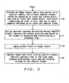
- Fig. 5 illustrates a flowchart of a method invented to achieve a precise timing of a shutter of a digital camera, which can also be used as for a controllable aperture.
- the first step 50 illustrates providing an image sensor and a lens barrel of a digital camera, one or more shutter blades, which are moved by at least one linear motor, and said at least one linear motor, each motor comprising an iron, two coils, and at least one magnet fastened on a movable device, which is mechanically connected to the shutter blades.
- the next step 51 comprises setting up a desired aperture opening by moving shutter blades, wherein the actual position and speed of the blades is measured and controlled by a feedback loop,
- the speed of the blades can be reduced when they approach a final position, e.g. an aperture opening desired.
- the next step 52 illustrates a global reset to the image sensor.
- the last step 53 describes the capturing of an image and the totally closing of the shutter blades, wherein an exposure time is the time span between said global reset and the totally closing of the shutter blades.
- An integrated circuit controls one or more motors to drive the shutter. This IC can also control one or more motors/actuators to move a lens barrel if an auto focus function is provided with the camera module.
- the shutter system invented is able to trigger the imager. By knowing the position of the shutter blades, the shutter arrives at an aperture position desired by the position sensing disclosed above. Even during movements of the shutter blades the image sensor can be triggered by the shutter control. The benefit is, there is no electronic or mechanical delay for the acceleration.
- the shutter is able to change continuously the aperture's opening. This function is important for video and still cameras. It is possible to have a fixed exposure time and by changing the aperture's opening the brightness can be adjusted as desired.
Abstract
Description
- This application is related to the following European patent applications:
- DI08-006, titled "Camera Shutter and position control thereof',
- DI09-003/004, titled "Camera Module having a low-friction movable lens",
- DI09-007, titled "Twin-actuator configuration for a camera module", and
- DI09-012, titled "Drop Detection Using Lens Position Sensing of Camera Module",
- All applications being filed on 19. January 2010 by the Applicant of the present application and being incorporated by reference into this application.
- This invention relates generally to digital cameras and relates more specifically to camera shutters driven by a linear motor.
- In photography, a shutter is a device that allows light to pass for a determined period of time, for the purpose of exposing photographic film or a light-sensitive electronic sensor to light to capture a permanent image of a scene.
- As light travels through a lens opening (aperture), the shutter opens and closes in a timed fashion to determine how long the image sensor ("film") gets exposed to a scene. The exposure time has a most important impact upon the quality of an image. Conventional film cameras are using usually mechanical shutters while digital cameras are often using digital shutters. It is a challenge for the designers of digital cameras to design a shutter mechanism for digital cameras that can be exactly controlled.
- The aperture of an optical system is the opening that determines the cone angle of a bundle of light rays that come to a focus in the image plane. The aperture determines how collimated the admitted rays are, which is of great importance for the appearance at the image piane. A narrow aperture wiii result in sharpness at the image plane, while a wide aperture will result in sharpness for light rays with the right focal length only. This means that a wide aperture results in an image that is sharp around what the lens is focusing on and blurred otherwise. The aperture also determines how many of the incoming rays are actually admitted and thus how much light that reaches the image plane, i.e. the narrower the aperture, the darker the image.
- In addition, with the advancement of small portable terminals equipped with cameras having zoom functions and shutters there is a requirement of compact size shutters. Therefore there is a need of precise, compact size shutters, which are easily to be assembled.
- Solutions dealing with camera shutters are described in the following patents or patent publications:
- U.S. Patent (
US 6,733,192 to Watanabe ) teaches an electromagnetic actuator having a rotor magnetized to have a plurality of poles; a base rotatably supporting the rotor; a yoke having a plurality of magnetic pole portions that are formed so as to face an outer peripheral surface of the rotor and that generate different magnetic poles; a magnetizing coil; and a bobbin/presser member which is disposed on an outer periphery of the yoke, around which the coil is wound, and with which a pressing portion for pressing the yoke against the base and for supporting the rotor is formed integrally. A camera blade driving device according to the present invention has a base having an exposure opening; a shutter blade or a diaphragm blade that is rotatably supported by the base; and an electromagnetic actuator including a rotor that is magnetized to have a plurality of poles and that is rotatably supported by the base, a yoke having a plurality of magnetic pole portions that are formed so as to face an outer peripheral surface of the rotor and that generate different magnetic poles, a magnetizing coil, and a bobbin/presser member which is disposed on an outer periphery of the yoke, around which the coii is wound, and with which a pressing portion for pressing the yoke against the base and for supporting the rotor is formed integrally, the electromagnetic actuator driving the shutter blade or the diaphragm blade. Accordingly, the parts count is reduced, and the assembly task is simplified, while cost is lowered. - U. S. Patent (
US 7,350,990 to Shin et al. ) discloses a shutter device for use with a camera lens assembly, wherein the shutter device includes a shutter base, a shutter blade which is rotatably mounted on the shutter base, a magnet movably coupled to the shutter base so as to enable rotation of the shutter blade, and a yoke extending lengthwise while facing the magnet wherein the movement range of the shutter base is limited within a length of the yoke. The zoom-in/zoom-out operation is enabled by moving only the shutter base, thus enabling a compact size fabrication of the camera lens assembly. The shutter blade is easily installed adjacent to a diaphragm, and the operational speed of the shutter blade is controlled by adjusting the structure of an electronic coil. - U. S. Patent Publication (
US 2007/0110433 to Masahiko ) describes a shutter driving apparatus for a camera module having a shutter driving section constructed to slidingly move shutter blades provided to a camera lens module in both sideward directions to thereby open and close a lens opening. The shutter driving apparatus comprises a lens housing; a pair of shutter blades provided to the lens housing to be slidingly moved in a lengthwise direction of the lens housing to thereby open and close a lens opening of the camera lens module; and a pair of shutter driving sections respectively connected to the shutter blades via rotation links and each being configured for creating a pair of electromagnetically-opposite electromagnet poles and having a permanent magnet positioned between the poles such that a permanent magnet with at least one of the poles and connected to the rotation link is rotated due to a magnetic field created as current is applied to the electromagnet, to slidingly move an associated shutter blade. - A principal object of the present invention is to achieve methods and systems to achieve a camera having precise timing of a shutter of the camera, which can be used also for a continuously controllable aperture
- A further object of the present invention is to control the shutter by a feedback loop.
- A further object of the present invention is to drive the blades of a shutter by at least one linear motor.
- Another object of the present invention is to sense the actual position and speed of the shutter blades by capacitive, inductive or Hall sensors.
- Furthermore an object of the present invention is to achieve an aperture, which can be set continuously.
- Moreover an object of the present invention is to achieve an aperture, which can be used for video cameras.
- Another further object of the present invention is that no flex wires are required inside the case of the shutter.
- In accordance with the objects of this invention a method to achieve a precise timing of a shutter of a digital camera, which can be used also for a continuously controllable aperture has been disclosed. The method invented comprises, firstly, the steps of (1) providing an image sensor and a lens barrel of a digital camera, shutter blades moved by at least one linear motor, wherein each linear motor comprises a coil, iron and at least one magnet fastened on a movable device being connected to the shutter blades. The next step teaches (2) setting up a desired aperture opening by moving the shutter blades, wherein the actual position and speed of the shutter blades is measured and controlled by a feedback loop The following steps are (3) applying a global reset to said image sensor, and (4) capturing an image and closing totally the shutter blades, wherein exposure time is the time span between said global reset and the totally closing of the shutter blades.
- In accordance with the objects of this invention a camera having a precise timing of its camera shutter, which can be used also for a continuously controllable aperture, has been disclosed. The camera invented comprises, firstly, an image sensor, a movable lens barrel, one or more actuators to move said lens barrel, and a means to guide the movements of the lens barrel. Furthermore the camera invented comprises a shutter case, and one or more shutter blades, wherein each of the shutter blades is rotatably mounted on the shutter case and the shutter blades are moved by at least one linear motor. Moreover the camera invented comprises said at least one linear motor to move said one or more blades, wherein each motor comprises: at least one coil wrapped around a piece of iron, wherein said iron is fastened on said shutter case and at least one magnet, fastened on a device, which is mechanically connected to the shutter blades. Finally the camera comprises an integrated circuit controlling the motor driving the shutter and the actuators moving the lens barrel and at least one position sensor, sensing a position of said shutter blades.
- In accordance with the objects of this invention a camera having a precise timing of its camera shutter, which can be used also for a continuously controllable aperture, has been disclosed. The camera invented comprises, firstly, a shutter case, and at least two shutter blades, wherein each of the blades is rotatably mounted on the shutter case and the blades are moved by at least one linear motor. Furthermore the system comprises at least one linear motor to move said blades, wherein each motor comprises at least one coil wrapped around a piece of iron, wherein said iron is fastened on said shutter case, and a magnet, fastened on a shutter blade. Finally the system invented comprises at least one position sensor, sensing a position of said shutter blades.
- In the accompanying drawings forming a material part of this description, there is shown:
-
Fig. 1 shows a preferred embodiment of the shutter invented. The shutter is mounted on top of the lens barrel (not visible) or on top of the moving part of the lens system. -
Fig. 2a shows an assembled view of major components of a linear motor used for the present invention. -
Fig. 2b shows an exploded view of the linear motor used for the present invention. -
Fig. 3 illustrates a basic arrangement of a capacitive sensor sensing the position of shutter blades. -
Fig. 4 shows an exploded view of an implementation of the shutter invented. -
Fig. 5 illustrates a flowchart of a method invented to achieve a precise timing of a camera shutter, which can be used also for a controllable aperture. - The preferred embodiments disclose methods and systems for shutters of cameras. The shutters invented are based on regulated feedback loops. The actual position of a shutter, the speed of the shutter and the shutter delay time can be constantly measured and controlled, enabling very fast shutter speed, and delay time. Furthermore the shutter can be used as an aperture even for video cameras because the aperture opening can be controlled continuously.
- A global reset function is provided for the image sensor of the camera. The global reset is opening (activating) every pixel of the image sensor after the shutter is opened to a defined aperture opening. In order to achieve a short active light exposure time (below 1 ms), after the global reset, the mechanical shutter invented closes rapidly after a defined light exposure time. An active light exposure time is the time span between the image sensor is activated and the mechanical shutter is closed. In order to achieve a precise timing the shutter of the present invention uses electronic control and a feedback loop to control the actual position of the shutter.
- A key advantage of the shutter invented is that it will be moved together with a lens barrel in order to reach a desired position, e.g. a suitable focus position. The shutter invented shutter is fastened on the lens barrel and it doesn't require any flexible cable inside the lens barrel to be moved with the shutter.
-
Fig. 1 shows a preferred embodiment of the camera shutter invented. The shutter is mounted on top of the lens barrel (not visible) or on top of the moving part of the lens system. - The
coils 2 of two bidirectional linear motors drivingshutter blades 6 are wrapped around iron coil cores 1. Thecoils 2 and iron coil cores 1 are mounted on the case of the shutter and inside of a lens barrel of a zoom lens system. Furthermore in a preferred embodiment each linear motor driving shutter blades comprises twomagnets 7 fastened onshutter blades 6 or on a movable yoke, which is mechanically connected to theshutter blades 6. The magnets are moved by magnetic force depending upon the currents through thecoils 2 and the linear motors are moving theshutter blades 6 directly or via theyoke 8. The opening 3 defines the size of the aperture. - Depending upon the type of linear motor used the
permanent magnets 7 could be replaced by a magnetic metal, such as iron. It would also be possible to use one permanent magnet instead of two magnets. - The shutter case can move, together with the
blades 6, coils 2 and coil cores 1, up and down along the optical axis of the camera depending upon the movements of the zoom lens barrel. Thecoils 2 are located on a fixed part of the shutter system. The energy to move the shutter blades comes from the coils. No flexible wires are required to drive the motors. - Any number of blades can be used if they are all mechanically connected by a yoke or any other mechanical connection. In a preferred embodiment two linear motors are used to move the blades. By using two adjacent linear motors the magnetic force to the centre will be minimized. Alternatively using one linear motor is possible as well
- Another linear motor 4 positions the lens barrel to a zooming or focus position.
Balls 5 enable the movement of the lens positioning system inclusive of the shutter system. Theshutter blades 6 move perpendicular to the optical axis of the camera. Theshutter blades 6 themselves are driven by two linear motors having each twocoils 2 and a two correspondent pieces of magnetic material fastened on theyoke 8. By supplying a current through the coils the correspondent magnets of the yoke will move together with theyoke 8 and theblades 6 in a direction dependent upon the direction of the current. Theblades 6, which are mechanically connected to theyoke 8 are turning around their axis (not shown). -
Fig. 2a shows an assembled view of simplified major components of alinear motor 20, which can be used to control the shutter blades of a camera. The linear motor comprises acoil core 22 around which twocoils 21 are wrapped. Thecoil core 22 is made of magnetic material, as e.g. iron. In order to avoid unnecessary complexity the coil core ofFig. 2a has a straight shape. The shape of the coil core can be adapted to specific requirements. Actually, as shown inFig. 1 , the coil core 1 can be slightly bent to support circular movements of theblades 6 or of a yoke. - Furthermore the linear motor of
Fig. 2a has ametallic case 24 containing twopermanent magnets 23. -
Fig. 2b shows an exploded view of thelinear motor 20. It shows again thecoil core 22, twocoils 21, twopermanent magnets 23, and themetallic case 24. - In one embodiment of the invention, using inductive methods to measure the position of the blades, is the linear motor moving the blades also used to sense the actual position of the blades. If the motor is moving, the
metallic case 24 together with the magnets will cover thecoils 23 more or less, i.e. the inductance changes with the actual position of themetallic case 24 with themagnets 23, thus enabling to sense the position of the blades. The difference of the inductance of the twocoils 23 is correlated to the position of the blades. - The position and the speed of the blades can be measured and controlled by a feedback loop. The position of the blades can be sensed by measuring the difference of inductance as outlined above or by using a capacitive sensor to sense the position of the blades. For a capacitive sensor is that only flat plates are required. Alternatively Hall sensors can also be used.
-
Fig. 3 illustrates a basic arrangement of acapacitive sensor 30. The sensor comprises atop sensor plate 31 and abottom sensor plate 32. The capacitance of this arrangement depends upon the actual position of a movingshutter blade 6 and hence the actual position of ablade 6 can be measured by measuring the capacitance between bothsensor plates - There is a correlation between the actual position of the blades and the opening of the aperture formed by the blades. Therefore a desired opening can be established by controlling the movements of the blades. Furthermore it has to be noted that no electrical connection is required to the moving parts of the shutter.
- The blades of the shutter are moving continuously when the shutter is closing. This means that, when the movement of the blades is stopped, a stable position of the blades is reached and an aperture of any size can be achieved. The shutter positioning has actually two functions, controlling the position and the speed. This means that the shutter invented can take over the function of an aperture because any size of an aperture allowed by the lens barrel can be implemented before capturing an image. It should be noted that the aperture can be controlled continuously, e.g. for video cameras. This can significantly improve the quality of an image.
-
Fig. 4 shows an exploded view of an implementation of the camera shutter invented.Fig. 4 shows twoholder plates 40 at the front and the back end of the shutter. FurthermoreFig. 4 shows twoshutter blades 6 having anaxis 7 to turn around and ashutter case 41. Alternatively only one shutter blade or more than two shutter blades could be used as well. In case a plurality of shutter blades is deployed the shutter blades can be mechanically connected via a yoke. Two linear motors comprising each an iron 1 and twocoils 2 follow in the illustration ofFig. 4 . By using linear motors, being mounted adjacently at each side of the shutter case, the magnetic force to the centre will be minimized. Alternatively only one motor could be used as well.Magnetic material lens barrel 8, which can be moved along the optical axis. - The camera module invented furthermore comprises an integrated circuit (IC) controlling the actuators of the present invention, an image sensor, and a movable lens barrel in order to support an auto focus function of the camera. This IC also controls actuators with integrated position control to move the lens barrel of the camera module as required as disclosed in the European patent application
DI09-003/004 DI09-007 -
Fig. 5 illustrates a flowchart of a method invented to achieve a precise timing of a shutter of a digital camera, which can also be used as for a controllable aperture. Thefirst step 50 illustrates providing an image sensor and a lens barrel of a digital camera, one or more shutter blades, which are moved by at least one linear motor, and said at least one linear motor, each motor comprising an iron, two coils, and at least one magnet fastened on a movable device, which is mechanically connected to the shutter blades. Thenext step 51 comprises setting up a desired aperture opening by moving shutter blades, wherein the actual position and speed of the blades is measured and controlled by a feedback loop, - In order to prevent a hard stop of the blades the speed of the blades can be reduced when they approach a final position, e.g. an aperture opening desired.
- The
next step 52 illustrates a global reset to the image sensor. Thelast step 53 describes the capturing of an image and the totally closing of the shutter blades, wherein an exposure time is the time span between said global reset and the totally closing of the shutter blades. - An integrated circuit (IC) controls one or more motors to drive the shutter. This IC can also control one or more motors/actuators to move a lens barrel if an auto focus function is provided with the camera module.
- It should be noted that the shutter system invented is able to trigger the imager. By knowing the position of the shutter blades, the shutter arrives at an aperture position desired by the position sensing disclosed above. Even during movements of the shutter blades the image sensor can be triggered by the shutter control. The benefit is, there is no electronic or mechanical delay for the acceleration.
- The shutter is able to change continuously the aperture's opening. This function is important for video and still cameras. It is possible to have a fixed exposure time and by changing the aperture's opening the brightness can be adjusted as desired.
- While the invention has been particularly shown and described with reference to the preferred embodiments thereof, it will be understood by those skilled in the art that various changes in form and details may be made without departing from the spirit and scope of the invention.
Claims (25)
- A method to achieve a precise timing of a shutter of a digital camera, which can be used also for a continuously controllable aperture comprising the following steps:(1) providing an image sensor and a lens barrel of a digital camera, one or more shutter blades moved by at least one linear motor, wherein each linear motor comprises a coil, iron and at least one magnet fastened on a device being connected to one or more shutter blades;(2) setting up a desired aperture opening by moving the shutter blades, wherein the actual position and speed of the shutter blades is measured and controlled by a feedback loop;(3) applying a global reset to said image sensor; and(4) capturing image and closing totally the shutter blades, wherein exposure time is the time span between said global reset and the totally closing of the shutter blades, wherein the actual position and speed of the shutter blades is measured and controlled by said feedback loop.
- The method of claim 1 wherein two bidirectional linear motors are moving the shutter blades.
- The method of claim 1 wherein the iron of each of said at least one linear motor is fastened on a case of the camera shutter.
- The method of claim 1 wherein sensors are measuring an actual position of said shutter blades.
- The method of claim 4 wherein said sensors are capacitive sensors, or inductive sensors or Hall sensors.
- The method of claim 4 wherein sensors are measuring the speed of the shutter blades
- The method of claim 1 wherein a position of said shutter blades is controlled by a feedback loop.
- The method of claim 1 wherein said magnets are fastened on a movable yoke, which is mechanically connected to the shutter blades.
- The method of claim 1 wherein two shutter blades are used.
- The method of claim 1 wherein the aperture is controlled continuously.
- The method of claim 1 wherein the shutter is used for a video camera, wherein the aperture is controlled continuously.
- A camera having a precise timing of its camera shutter which can be used also for a continuously controllable aperture comprises:- an image sensor;- a movable lens barrel;- one or more actuators to move said lens barrel;- a means to guide the movements of the lens barrel;- a shutter case;- one or more shutter blades, wherein each of the shutter blades is rotatably mounted on the shutter case and the shutter blades are moved by at least one linear motor;- said at least one linear motor to move said one or more blades, wherein each motor comprises:at least one coil wrapped around a piece of iron, wherein said iron is fastened on said shutter case; andat least one magnet, fastened on a device, which is mechanically connected to the shutter blades;- an integrated circuit controlling the motor driving the shutter and the actuators moving the lens barrel; and- at least one position sensor, sensing a position of said shutter blades.
- The camera module of claim 12 wherein said means to guide the movements of the lens barrel are ball bearings.
- A camera having a precise timing of its camera shutter which can be used also for a continuously controllable aperture comprises:a shutter case;one or more shutter blades, wherein each of the shutter blades is rotatably mounted on the shutter case and the shutter blades are moved by at least one linear motor;said at least one linear motor to move said one or more blades, wherein each motor comprises:at least one coil wrapped around a piece of iron, wherein said iron is fastened on said shutter case; andat least one magnet, fastened on a device, which is mechanically connected to the shutter blades; andat least one position sensor, sensing a position of said shutter blades.
- The camera of claim 14 wherein two shutter blades are used.
- The camera of claim 14 wherein said sensors are capacitive sensors, magnetic sensors or Hall sensors.
- The camera of claim 14 wherein each linear motor has two coils or two magnets.
- The camera of claim 14 wherein each linear moter has two magnets contained in a metallic case.
- The camera of claim 18 wherein said shutter case can be moved by a linear motor.
- The camera of claim 16 wherein said shutter case is being moved by using balls.
- The camera of claim 14 wherein said movements of said blades can be stopped any time in order to achieve an aperture of a desired size.
- The camera of claim 14 wherein said shutter case is a movable shutter case adapted for slideable arrangement in direction of an optical axis of lens system of the camera.
- The camera of claim 14 wherein said a device, which is mechanically connected to the shutter blades is a yoke.
- The camera of claim 14 wherein said aperture is controlled continuously.
- The camera of claim 14 wherein said shutter is used for a video camera.
Priority Applications (2)
| Application Number | Priority Date | Filing Date | Title |
|---|---|---|---|
| EP10368002A EP2345929A1 (en) | 2010-01-19 | 2010-01-19 | Camera shutter |
| US12/658,508 US8773582B2 (en) | 2010-01-19 | 2010-02-05 | System and Method for controlling a camera shutter |
Applications Claiming Priority (1)
| Application Number | Priority Date | Filing Date | Title |
|---|---|---|---|
| EP10368002A EP2345929A1 (en) | 2010-01-19 | 2010-01-19 | Camera shutter |
Publications (1)
| Publication Number | Publication Date |
|---|---|
| EP2345929A1 true EP2345929A1 (en) | 2011-07-20 |
Family
ID=42078821
Family Applications (1)
| Application Number | Title | Priority Date | Filing Date |
|---|---|---|---|
| EP10368002A Withdrawn EP2345929A1 (en) | 2010-01-19 | 2010-01-19 | Camera shutter |
Country Status (2)
| Country | Link |
|---|---|
| US (1) | US8773582B2 (en) |
| EP (1) | EP2345929A1 (en) |
Families Citing this family (2)
| Publication number | Priority date | Publication date | Assignee | Title |
|---|---|---|---|---|
| KR101959251B1 (en) * | 2017-01-26 | 2019-03-18 | 자화전자(주) | Apparatus for driving iris of camera |
| KR102194709B1 (en) * | 2018-08-28 | 2020-12-23 | 삼성전기주식회사 | Camera module |
Citations (10)
| Publication number | Priority date | Publication date | Assignee | Title |
|---|---|---|---|---|
| US4240728A (en) * | 1977-06-27 | 1980-12-23 | Prontor-Werk Alfred Gauthier Gmbh | Photographic camera shutter electromagnetic system for controlling photographic light admitted to camera |
| JPS58139106A (en) * | 1982-02-12 | 1983-08-18 | Canon Inc | Lens bareel incorporated with motor |
| JPH02226130A (en) * | 1989-02-28 | 1990-09-07 | Canon Electron Inc | Light quantity controller |
| US5264896A (en) * | 1992-05-18 | 1993-11-23 | Eastman Kodak Company | Continuously variable electronically actuated shuttering system |
| US5517243A (en) * | 1990-10-04 | 1996-05-14 | Canon Kabushiki Kaisha | Image sensing apparatus with control of charge storage time |
| JP2001281724A (en) * | 2000-03-31 | 2001-10-10 | Nidec Copal Corp | Camera shutter |
| US20040062542A1 (en) * | 2002-06-25 | 2004-04-01 | Nobuaki Watanabe | Electromagnetic actuator and camera blade driving device |
| JP2005215566A (en) * | 2004-02-02 | 2005-08-11 | Alps Electric Co Ltd | Shutter device |
| US20060147198A1 (en) * | 2005-01-03 | 2006-07-06 | Samsung Electronics Co.; Ltd | Shutter device for camera lens assembly |
| US20070110433A1 (en) | 2005-11-17 | 2007-05-17 | Samsung Electronics Co.; Ltd | Shutter driving apparatus for camera module |
Family Cites Families (4)
| Publication number | Priority date | Publication date | Assignee | Title |
|---|---|---|---|---|
| JP2007251382A (en) * | 2006-03-14 | 2007-09-27 | Sony Corp | Imaging apparatus |
| US7604422B2 (en) * | 2006-12-11 | 2009-10-20 | Massachusetts Institute Of Technology | Large-aperture focal plane shutter |
| US8128296B2 (en) * | 2009-01-26 | 2012-03-06 | Va, Inc. | Shutter assembly |
| US8313255B2 (en) * | 2009-01-26 | 2012-11-20 | Va, Inc. | Shutter assembly with drive ring-mounted magnet |
-
2010
- 2010-01-19 EP EP10368002A patent/EP2345929A1/en not_active Withdrawn
- 2010-02-05 US US12/658,508 patent/US8773582B2/en not_active Expired - Fee Related
Patent Citations (12)
| Publication number | Priority date | Publication date | Assignee | Title |
|---|---|---|---|---|
| US4240728A (en) * | 1977-06-27 | 1980-12-23 | Prontor-Werk Alfred Gauthier Gmbh | Photographic camera shutter electromagnetic system for controlling photographic light admitted to camera |
| JPS58139106A (en) * | 1982-02-12 | 1983-08-18 | Canon Inc | Lens bareel incorporated with motor |
| JPH02226130A (en) * | 1989-02-28 | 1990-09-07 | Canon Electron Inc | Light quantity controller |
| US5517243A (en) * | 1990-10-04 | 1996-05-14 | Canon Kabushiki Kaisha | Image sensing apparatus with control of charge storage time |
| US5264896A (en) * | 1992-05-18 | 1993-11-23 | Eastman Kodak Company | Continuously variable electronically actuated shuttering system |
| JP2001281724A (en) * | 2000-03-31 | 2001-10-10 | Nidec Copal Corp | Camera shutter |
| US20040062542A1 (en) * | 2002-06-25 | 2004-04-01 | Nobuaki Watanabe | Electromagnetic actuator and camera blade driving device |
| US6733192B2 (en) | 2002-06-25 | 2004-05-11 | Nidec Copal Corporation | Electromagnetic actuator and camera blade driving device |
| JP2005215566A (en) * | 2004-02-02 | 2005-08-11 | Alps Electric Co Ltd | Shutter device |
| US20060147198A1 (en) * | 2005-01-03 | 2006-07-06 | Samsung Electronics Co.; Ltd | Shutter device for camera lens assembly |
| US7350990B2 (en) | 2005-01-03 | 2008-04-01 | Samsung Electronics Co., Ltd. | Shutter device for camera lens assembly |
| US20070110433A1 (en) | 2005-11-17 | 2007-05-17 | Samsung Electronics Co.; Ltd | Shutter driving apparatus for camera module |
Also Published As
| Publication number | Publication date |
|---|---|
| US20110176053A1 (en) | 2011-07-21 |
| US8773582B2 (en) | 2014-07-08 |
Similar Documents
| Publication | Publication Date | Title |
|---|---|---|
| KR102299752B1 (en) | Optical path folding element with extended two-degree-of-freedom rotation range | |
| US9494769B2 (en) | Multi-lens imaging module and actuator with auto-focus adjustment | |
| US8428451B2 (en) | Interchangeable zoom lens actuator | |
| US20060152591A1 (en) | Automatic focus mechanism of an image capturing device | |
| US20060228099A1 (en) | Digital camera with electromagnetic focusing module | |
| EP1972991A2 (en) | Vibration reduction unit, lens barrel and camera | |
| KR100582746B1 (en) | Imaging Device | |
| KR100732494B1 (en) | Iris Apparatus having Function of Shutter and the Iris Apparatus Controlling method thereof | |
| JP2006330314A (en) | Light quantity adjusting device, imaging optical unit and imaging apparatus | |
| US8773582B2 (en) | System and Method for controlling a camera shutter | |
| JP2012013896A (en) | Optical instrument | |
| EP2341380A2 (en) | Twin-actuator configuration for a camera module | |
| US8547477B2 (en) | Camera shutter and position control thereof | |
| KR20110026337A (en) | Shutter device and micro camera have the same | |
| US11586095B2 (en) | Lens apparatus and camera system having the same | |
| WO2020003942A1 (en) | Lens barrel and image capturing device | |
| JP2017151312A (en) | Lens barrel, lens unit and lens unit manufacturing method | |
| KR101874431B1 (en) | Auto focusing apparatus for three dimensional camera module | |
| KR100562721B1 (en) | Small camera device for communication machine | |
| KR100866769B1 (en) | Device to focus automatically in optical lens for mobile phone | |
| JP5047460B2 (en) | Imaging optical unit and imaging apparatus | |
| JP5047459B2 (en) | Light amount adjusting device, imaging optical unit, and imaging device | |
| JP2005309318A (en) | Diaphragm mechanism and camera using same | |
| CN218547191U (en) | Iris diaphragm camera driving device | |
| KR20110127805A (en) | Device for shutter of camera module |
Legal Events
| Date | Code | Title | Description |
|---|---|---|---|
| PUAI | Public reference made under article 153(3) epc to a published international application that has entered the european phase |
Free format text: ORIGINAL CODE: 0009012 |
|
| AK | Designated contracting states |
Kind code of ref document: A1 Designated state(s): AT BE BG CH CY CZ DE DK EE ES FI FR GB GR HR HU IE IS IT LI LT LU LV MC MK MT NL NO PL PT RO SE SI SK SM TR |
|
| AX | Request for extension of the european patent |
Extension state: AL BA RS |
|
| RAP1 | Party data changed (applicant data changed or rights of an application transferred) |
Owner name: DIGITAL IMAGING SYSTEMS GMBH |
|
| 19U | Interruption of proceedings before grant |
Effective date: 20110930 |
|
| 19W | Proceedings resumed before grant after interruption of proceedings |
Effective date: 20120801 |
|
| 17P | Request for examination filed |
Effective date: 20121120 |
|
| STAA | Information on the status of an ep patent application or granted ep patent |
Free format text: STATUS: THE APPLICATION IS DEEMED TO BE WITHDRAWN |
|
| 18D | Application deemed to be withdrawn |
Effective date: 20130801 |