EP2345871A2 - Synchronisierung der Ausrichtung eines 3D-Messgeräts und Ausrichtung einer intelligenten Führungsvorrichtung - Google Patents
Synchronisierung der Ausrichtung eines 3D-Messgeräts und Ausrichtung einer intelligenten Führungsvorrichtung Download PDFInfo
- Publication number
- EP2345871A2 EP2345871A2 EP20100152002 EP10152002A EP2345871A2 EP 2345871 A2 EP2345871 A2 EP 2345871A2 EP 20100152002 EP20100152002 EP 20100152002 EP 10152002 A EP10152002 A EP 10152002A EP 2345871 A2 EP2345871 A2 EP 2345871A2
- Authority
- EP
- European Patent Office
- Prior art keywords
- igd
- earth
- coordinate system
- gravity
- transformation
- Prior art date
- Legal status (The legal status is an assumption and is not a legal conclusion. Google has not performed a legal analysis and makes no representation as to the accuracy of the status listed.)
- Granted
Links
Images


Classifications
-
- G—PHYSICS
- G01—MEASURING; TESTING
- G01C—MEASURING DISTANCES, LEVELS OR BEARINGS; SURVEYING; NAVIGATION; GYROSCOPIC INSTRUMENTS; PHOTOGRAMMETRY OR VIDEOGRAMMETRY
- G01C21/00—Navigation; Navigational instruments not provided for in groups G01C1/00 - G01C19/00
- G01C21/20—Instruments for performing navigational calculations
-
- G—PHYSICS
- G01—MEASURING; TESTING
- G01C—MEASURING DISTANCES, LEVELS OR BEARINGS; SURVEYING; NAVIGATION; GYROSCOPIC INSTRUMENTS; PHOTOGRAMMETRY OR VIDEOGRAMMETRY
- G01C15/00—Surveying instruments or accessories not provided for in groups G01C1/00 - G01C13/00
- G01C15/002—Active optical surveying means
Definitions
- the present invention relates to the field of the use of Intelligent Guidance Devices (IGD) for guiding measurement processes using 3D graphics.
- IGD Intelligent Guidance Devices
- a 3D Measurement Device is a measurement system capable of measuring the (x, y, z) coordinates of points on physical parts in the 3-dimensional space, using anyone of many known measurement principles. These devices are used in many different manufacturing industries for quality assurance procedures.
- the devices are made to be portable such that they may be easier to handle and manipulate.
- they since they have their own coordinate system, they are not necessarily compatible with other existing technologies. Images or measurements taken with these devices cannot easily be transferred to other imaging devices without losing some information attached to the coordinate system.
- an intelligent guidance device having an internal 3D coordinate system O IGD , X IGD , Y IGD , Z IGD , the device comprising: a gravity direction measurement device; an electronic compass; an IGD transformation module operatively connected to the IGD and adapted to define a coordinate system O IGD-Earth , X IGD-Earth , Y IGD-Earth , Z IGD - Earth using a direction opposite to gravity as Z IGD-Earth and a direction corresponding to the magnetic north pole as Y IGD-Earth , and to compute and apply a rigid transformation T IGD-To-IGDEarth to transform O IGD , X IGD , Y IGD , Z IGD to O IGD-Earth , X IGD-Earth , Y IGD-Earth , Z IGD-Earth ; and a display device for displaying 3D graphics in a 3D coordinate system synchronized with a 3D coordinate
- At least one computer program product for synchronizing a three-dimensional measurement device (3DM) having an internal 3D coordinate system O 3DM , X 3DM , Y 3DM , and Z 3DM , with an intelligent guidance device (IGD) having a display device, a gravity direction measurement device, an electronic compass, and an internal 3D coordinate system O IGD , X IGD , Y IGD , Z IGD , comprising instruction means encoded on a computer-readable medium, for causing operations of: defining a coordinate system O IGD - Earth , X IGD - Earth , Y IGD-Earth , Z IGD-Earth using a direction opposite to gravity as Z IGD-Earth and a direction corresponding to the magnetic north pole as Y IGD-Earth , from a perspective of the IGD; computing and applying a rigid transformation T IGD-To-IGDEarth to transform O IGD , X IGD , Y IGD
- 3D Coordinate System A system for assigning 3 numbers to each point in a 3-dimensional space.
- a common instance of a 3D Coordinate System is the Cartesian coordinate system where three X, Y, Z axes perpendicular to each other and meeting each other at an origin point (0, 0, 0) are used to parameterize the 3-dimensional space (see Figure 1 ).
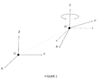
- An infinite number of 3D Coordinate Systems can be derived from the basic Cartesian coordinate system by moving (or translating) the origin point in 3-dimensional space, defining a new origin O', and rotating the original X, Y, Z axes to define new axes X', Y', and Z' (see Figure 2 ).
- the X', Y', and Z' axes can each be expressed by using a triplet of (x, y, z) coordinates, expressed in the Cartesian coordinate system.
- the triplet of (x, y, z) coordinates representing a particular axis is computed by determining a point P located at a distance of 1 from the origin O' along the direction of the axis, and then subtracting the origin O' from this point P.
- a 3D Coordinate System is said to be right-handed if the vector product between the first axis (for example X) and the second axis (for example Y) produces the third axis (for example Z).
- a 3D Coordinate System would be left-handed if the vector product between the second axis and the first axis would produce the third axis.
- This document uses right-handed 3D Coordinate Systems in all explanations. However, left-handed 3D Coordinate Systems could be used as well without loss of generality.
- 3D Transformation A mathematical operation that transforms any input point (x i , y i , z i ) in 3-dimensional space into an output point (x o , y o , z o ) .
- Rigid 3D Transformations are subsets of the possible 3D Transformations applicable to input points by which only rotations and translations are applied to these points. Such a 3D Transformation is called rigid because it preserves the original shape and dimensions of any 3-dimensional object. For example, let's imagine a box having a width of 1 meter, a height of 2 meters, and a depth of 3 meters. Then, let's consider any possible Rigid 3D Transformation that can be applied to this box. If any of these possible Rigid 3D Transformations are applied to the box, the box dimensions would always remain 1 meter by 2 meters by 3 meters under all circumstances.
- a Rigid 3D Transformation RT can be expressed by six numbers (r x , r y , r z , t x , t y , t z ).
- the numbers r x , r y , and r z represent successive rotations to be applied about the X, Y, and Z axes of the Cartesian coordinate system.
- the numbers t x , t y , and t z represent successive translations to be applied along the X, Y, and Z axes of the Cartesian coordinate system.
- Rigid 3D Transformations can also be applied to 3D Coordinate Systems.
- Four points are needed to define an arbitrary 3D Coordinate System: the origin O', and the points at a unitary distance of 1 from O' along the X', Y', and Z' axes.
- a Rigid 3D Transformation is applied to a 3D Coordinate System by transforming the four points that are needed to describe it.
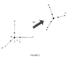
- the origin and three axes of the transformed 3D Coordinate System may then be rebuilt from the four transformed points by subtracting the transformed origin from the three transformed points at the extremity of the unitary axes (see Figure 3 ).
- Gravity Direction Measurement Device A measurement device that is capable of measuring the direction of gravity, such as a three-axis accelerometer or an inclinometer. Gravity direction measurement devices can be incorporated in computing devices. If the computing device is not moved abruptly, the gravitational force becomes the only major force influencing the gravity direction measurement device readings. The gravitational force generally points towards the center of Earth with a relatively stable intensity locally.
- Electronic Compass A measurement device that can determine the direction of the Earth's North magnetic pole.
- An electronic compass can be incorporated in computing devices. Locally, the measurements produced by an electronic compass are fairly constant.
- the North direction can be used not only for geographical navigation purposes, but also as a fixed reference direction to define a coordinate system.
- Display Device A material support to visually output information to an end-user, such as text, images, videos, etc.
- Computing devices are generally equipped with display devices.
- IGD Intelligent Guidance Device
- An example of an IGD is the iPhone TM 3GS model.
- 3D Measurement Device A measurement system capable of measuring the (x, y, z) coordinates of points on physical parts in the 3-dimensional space. Any measurement principle can be used.
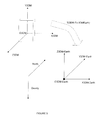
- Fig. 1 illustrates a Cartesian coordinate system with a point parametrized in a 3-dimensional space, in accordance with one embodiment
- Fig. 2 illustrates the Cartesian coordinate system of Fig. 1 and a second 3D coordinate system defined by translating and rotating the Cartesian coordinate system, in accordance with one embodiment
- Fig. 3 illustrates how a 3D coordinate system is transformed by a Rigid 3D Transformation, in accordance with one embodiment
- Fig. 4a illustrates the transformation of an IGD 3D coordinate system to orient it with respect to gravity and the North direction, in accordance with one embodiment
- Fig. 4b illustrates the axis adjustment operation, in accordance with one embodiment
- Fig. 5 illustrates the transformation of a 3DM 3D coordinate system to orient it with respect to gravity and the North direction, in accordance with one embodiment
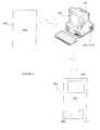
- Fig. 6 is a block diagram of a system for synchronizing a 3DM and an IGD where the transformation modules are integrated onto the respective devices, in accordance with one embodiment
- Fig. 7 is a block diagram of a system for synchronizing a 3DM and an IGD where a separate computing device is used for one of the transformation modules, in accordance with one embodiment
- Fig. 8 is a block diagram of a system for synchronizing a 3DM and an IGD where a separate computing device is used for both of the transformation modules, in accordance with one embodiment.
- a 3DM is a device designed to measure the (x, y, z) coordinates of points and report these measured coordinates from the perspective of its internal 3D Coordinate System defined by an origin O 3DM and three axes X 3DM , Y 3DM , and Z 3DM .
- An IGD is a device that also has an internal 3D Coordinate System defined by an origin O IGD and three axes X IGD , Y IGD , Z IGD .
- Figure 1 illustrates a Cartesian coordinate system having axes X, Y, and Z and an origin (0, 0, 0). A point (2, 3, 0) is parametrized in the 3-dimensional space.
- Figure 2 illustrates a new coordinate system defined by translating and rotating the Cartesian coordinate system of figure 1 . This new coordinate system has axes X', Y', Z'.
- the coordinate system defined by X', Y', Z' is further transformed by rigid 3D transformation RT by transforming four points and recomputing the axes such that we have X" , Y", Z” .
- These principles are used in order to synchronize the orientation of a 3DM 3D Coordinate System with the orientation of a IGD 3D Coordinate System.
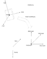
- the direction of gravity is measured and a vector Z IGD-Earth pointing in a direction opposite to gravity (up) is determined.
- the electronic compass of the IGD the direction of the North magnetic pole is measured and a vector Y IGD-Earth pointing in the North direction is determined.
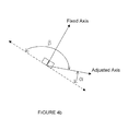
- Z IGD-Earth and Y IGD-Earth axes are computed from separate measurement devices, they are not perfectly perpendicular to each other. An adjustment operation is used to make them perpendicular to each other.
- a plane formed by Z IGD-Earth and Y IGD-Earth is defined.
- One of the two axes, for example Z IGD-Earth is fixed.
- the adjusted axis, for example Y IGD-Earth is then rotated in the plane to make it perpendicular to the fixed axis.
- the Y IGD-Earth could be used as the fixed axis, and the Z IGD-Earth axis could be rotated to make it perpendicular to Y IGD-Earth using the same method.
- the adjustment operation is illustrated in figure 4b .
- two positive rotation angles ⁇ and ⁇ less than or equal to 180° can be applied to the adjusted axis to make it perpendicular to the fixed axis.
- the smallest of ⁇ and ⁇ is used.
- a vector X IGD-Earth is found by computing the vector product between Y IGD-Eartn and Z IGD-Earth .
- An arbitrary origin O IGD-Earth is defined at (0, 0, 0).
- O IGD-Earth , X IGD-Earth , Y IGD-Earth , Z IGD - Earth represent a 3D Coordinate System where one of the axes points in a direction opposite to gravity and the other points towards North.
- a Rigid 3D Transformation T IGD-To-IGDEarth is computed to transform the IGD internal 3D Coordinate System O IGD , X IGD , Y IGD , Z IGD into the 3D Coordinate System O IGD-Earth , X IGD-Earth , Y IGD-Earth , Z IGD-Earth , as illustrated in Figure 4a .
- the direction of gravity is measured from the standpoint of the 3DM 3D Coordinate System. Any method known to the person skilled in the art may be used. For example, adjust a flat physical part using a level to bring its flat section perpendicular to gravity, measure the flat section with the 3DM, fit a plane on the measured points, and use the plane's normal vector to determine the direction of gravity. Alternatively, a gravity direction measurement device integrated to the 3DM may be used to determine the direction of gravity.
- a vector Z 3DM-Earth pointing in a direction opposite to gravity (up) may be determined.
- the direction of the North magnetic pole is measured from the standpoint of the 3DM 3D Coordinate System. Any method known to a person skilled in the art may be used. For example, use an electronic compass integrated to the 3DM, display the North direction on the IGD display device and use the 3DM to measure the displayed direction, or use a standard compass and use the 3DM to measure the direction indicated by the standard compass.
- a vector Y 3DM-Earth pointing in the North direction may be determined.
- a plane formed by Z 3DM-Earth and Y 3DM-Earth is then defined. If Y 3DM-Earth is not perfectly perpendicular to Z 3DM-Earth , either one of Z 3DM-Earth or Y 3DM-Earth may be rotated in the plane to bring the two perfectly perpendicular. Two positive rotation angles are possible, the smallest is used.
- a vector X 3DM-Earth is determined by computing the vector product between Y 3DM-Earth and 2 3DM-Earth .
- An origin O 3DM-Earth is defined at (0, 0, 0).
- O 3DM-Earth , X 3DM-Earth , Y 3DM-Earth , Z 3DM-Earth represent a 3D Coordinate System where one of the axes points in a direction opposite to gravity and the other points towards North.
- a Rigid 3D Transformation T 3DM-To-3DMEarth is computed and it brings the 3DM internal 3D Coordinate System O 3DM , X 3DM , Y 3DM , Z 3DM in total correspondence with 3D Coordinate System O 3DM-Earth , X 3DM-Earth , Y 3DM-Earth , Z 3DM-Earth , as illustrated in Figure 5 .
- the orientation of the IGD and the orientation of the 3DM are synchronized by transforming the internal 3D Coordinate System of the IGD by Rigid 3D Transformation T IGD-To-IGDEarth and transforming the internal 3D Coordinate System of the 3DM by Rigid 3D Transformation T 3DM-To-3DMEarth .
- the orientation of the IGD and the orientation of the 3DM are synchronized since the transformed X IGD and X 3DM axes are parallel to each other and point in the same direction, the transformed Y IGD and Y 3DM axes are parallel to each other and point in the same direction, and the transformed Z IGD and Z 3DM axes are parallel to each other and point in the same direction.
- the synchronization should be maintained at all times. Two cases may need to be specifically addressed.
- the first case is related to the nature of a typical IGD, which is that it is hand-held and can be rotated freely. Therefore, changes in the orientation of the IGD are to be monitored. If a change in the orientation of the IGD is detected, the Rigid 3D Transformation T IGD-To-IGDEarth should be updated by re-measuring the directions of gravity and North magnetic pole using the IGD gravity direction measurement device and electronic compass, and then updating the Rigid 3D Transformation T IGD-To-IGDEarth .
- measurement processes generally require the transformation of the 3DM 3D Coordinate System into other 3D Coordinate Systems, typically ones created in Computer-Aided Design (CAD) software.
- CAD Computer-Aided Design
- the invert of the Rigid 3D Transformation T 3DM-To-3DMEarth should be applied to both the 3D Coordinate System O IGD-Earth , X IGD-Earth , Y IGD-Earth , Z IGD-Earth and the 3D Coordinate System O 3DM-Earth , X 3DM-Earth , Y 3DM-Earth , Z 3DM-Earth .
- This operation transforms the IGD 3D Coordinate System into the internal 3DM 3D Coordinate System, while keeping the orientations synchronized. Then, an operator can determine a Rigid 3D Transformation transforming the internal 3DM 3D Coordinate System into the 3D Coordinate System of a model designed in CAD (Computer-Aided Design) software. This Rigid 3D Transformation would then be applied to both IGD and 3DM 3D Coordinate Systems in order to maintain their orientation synchronized. After the operation is applied, the axes of the transformed IGD 3D Coordinate System have the same orientation as the CAD model axes.
- the IGD can be used to guide a measurement process by means of 3D graphics displayed on the IGD display device.
- the following methodology demonstrates measurement guidance by means of 3D graphics.
- the orientation of the IGD and the orientation of the 3DM 3D Coordinate Systems are synchronized, as described above.
- the 3DM 3D Coordinate System is usually transformed to bring it into a more useful position and orientation. For example, points are measured on a physical part or assembly, and these measured points are used to construct a transformation that transforms the 3DM 3D Coordinate System into a CAD 3D Coordinate System. Since synchronization is achieved and maintained, the IGD 3D Coordinate System is also transformed, and the IGD 3D Coordinate System axes will have the same orientation and direction compared to the corresponding CAD 3D Coordinate System axes.
- 3D graphics to be displayed on the IGD are determined by geometry defined in the CAD 3D Coordinate System.
- the following Rigid 3D Transformations are applied successively to this geometry: the invert of the 3DM-to-CAD Rigid 3D Transformation; T 3DM-To-3DMEarth ; the invert of T IGD-To-IGDEarth .
- the IGD display device may be used to display the specific section using 3D graphics.
- Guidance 3D graphics such as 3D arrows and 3D text annotations can be used to supply information to the operator and guide the measurement process. For example, if a given target point needs to be measured, 3D arrows indicating the current distance between the 3DM and the target point along the three axes can be displayed on the IGD display device. Because the 3D arrows are oriented along the axes of the physical part or assembly, they help the operator reaching the target position more quickly.
- Figure 6 illustrates an embodiment for a system for synchronizing the internal coordinate systems of a 3DM 600 and an IGD 604 in order to allow measurement guidance using the IGD 604.
- the 3DM 600 includes a display device 606 and a 3DM transformation module 602 is integrated inside the 3DM 600.
- the 3DM transformation module 602 is a software product adapted to define the coordinate system O 3DM-Earth , X 3DM-Earth , Y 3DM-Earth , Z 3DM-Earth using the direction opposite to gravity as Z 3DM-Earth and the direction corresponding to the magnetic north pole as Y 3DM-Earth , from the perspective of the 3DM.
- the 3DM transformation module 602 will then compute the rigid transformation T 3DM-To-3DMEarth to transform O 3DM , X 3DM , Y 3DM , and Z 3DM to O 3DM-Earth , X 3DM-Earth , Y 3DM-Earth, Z 3DM-Earth .
- This rigid transformation can then be applied to the internal coordinate system of the 3DM 600.
- Figure 6 also illustrates the IGD 604 with which the 3DM 600 is being synchronized.
- the IGD 604 also has a display device 606.
- a gravity direction measurement device 608 and an electronic compass 612 are integrated inside the IGD 604.
- an IGD transformation module 610 which is a software product adapted to define the coordinate system O IGD-Earth , X IGD-Earth , Y IGD-Earth , Z IGD-Earth using the direction opposite to gravity as Z IGD-Earth and the direction corresponding to the magnetic north pole as Y IGD-Earth , from the perspective of the IGD 604.
- the IGD 604 computes and applies a rigid transformation T IGD-To-IGDEarth to transform O IGD , X IGD , Y IGD , Z IGD to O IGD-Earth , X IGD-Earth , Y IGD-Earth , Z IGD-Earth .
- a specially adapted 3DM 600 and a specially adapted IGD 604 are sufficient to perform the above-described synchronization and allow the IGD 604 to be used to display 3D graphics in a known direction and orientation.
- the IGD transformation module 610 and the 3DM transformation module 602 can be downloaded onto the respective devices via the internet or transferred from a storage medium such as a USB key, a scandisk, or any other type of memory device.
- the transfer of the software program onto the devices may be done in a wireless manner or a connected manner using one or more wires or cables.
- the modules 602, 610 may also be provided on the devices at the time of fabrication or manufacturing.
- the IGD 604 and the 3DM 600 may also be in communication together to transfer 3D images from one device to the other.
- This communication may be done in a wireless manner, such as Radio Frequency, WiFi, infrared, microwaves, etc.
- This communication may also be done in a connected manner using one or more wires or cables.
- Figure 7 illustrates a second embodiment of the system for synchronizing the IGD 604 and the 3DM 600.
- one of the transformation modules namely the 3DM transformation module 602 is on a computing device 614 separate from the 3DM 600.
- the transformation module on the computing device 614 may be the IGD transformation module 610 while the 3DM transformation module 602 is integrated in the 3DM 600, as per figure 6 .
- the computing device 614 has a display device 606.
- the computing device 614 may be a Personal Computer (PC), a laptop, a Personal Digital Assistant (PDA), or any other programmable machine that can store, retrieve, and process data and therefore includes at least one Central Processing Unit (CPU) that performs most calculations and includes a main memory, a control unit, and an arithmetic logic unit. Communications, wireless or connected, may occur between the 3DM 600 and the computing device 614, and between the computing device 614 and the IGD 604.
- PC Personal Computer
- PDA Personal Digital Assistant
- Communications wireless or connected, may occur between the 3DM 600 and the computing device 614, and between the computing device 614 and the IGD 604.
- Figure 8 illustrates a third embodiment of the system for synchronizing the IGD 604 and the 3DM 600.
- both of the transformation modules 602 and 610 are present on the separate computing device 614.
- the computing device 614 may be made up of one or more computers, or a network of computers, and is adapted to be in communication with the IGD 604 and the 3DM 600.
- IGD Idge Device
- the iPod Touch TM and the Nexus One TM also include all of the elements of an IGD. Any devices which have a display device, a gravity direction measurement device, and an electronic compass may be used. Examples of 3DM devices are the FaroArm TM , the PCMM from Romer, and the Leica Absolute Tracker TM .
- the present invention can be carried out as a method, can be embodied in a system, a computer readable medium or an electrical or electro-magnetic signal.
- the embodiments of the invention described above are intended to be exemplary only. The scope of the invention is therefore intended to be limited solely by the scope of the appended claims.
Landscapes
- Engineering & Computer Science (AREA)
- Radar, Positioning & Navigation (AREA)
- Remote Sensing (AREA)
- Physics & Mathematics (AREA)
- General Physics & Mathematics (AREA)
- Automation & Control Theory (AREA)
- Measuring Magnetic Variables (AREA)
- Navigation (AREA)
- Image Generation (AREA)
Applications Claiming Priority (1)
| Application Number | Priority Date | Filing Date | Title |
|---|---|---|---|
| US12/687,820 US8872889B2 (en) | 2010-01-14 | 2010-01-14 | Synchronization of the orientation of a 3D measurement device and the orientation of an intelligent guidance device |
Publications (3)
| Publication Number | Publication Date |
|---|---|
| EP2345871A2 true EP2345871A2 (de) | 2011-07-20 |
| EP2345871A3 EP2345871A3 (de) | 2011-12-14 |
| EP2345871B1 EP2345871B1 (de) | 2015-08-05 |
Family
ID=43942405
Family Applications (1)
| Application Number | Title | Priority Date | Filing Date |
|---|---|---|---|
| EP10152002.1A Active EP2345871B1 (de) | 2010-01-14 | 2010-01-28 | Synchronisierung der Ausrichtung eines 3D-Messgeräts und Ausrichtung einer intelligenten Führungsvorrichtung |
Country Status (3)
| Country | Link |
|---|---|
| US (1) | US8872889B2 (de) |
| EP (1) | EP2345871B1 (de) |
| CA (1) | CA2691246C (de) |
Families Citing this family (3)
| Publication number | Priority date | Publication date | Assignee | Title |
|---|---|---|---|---|
| US9423318B2 (en) * | 2014-07-29 | 2016-08-23 | Honeywell International Inc. | Motion detection devices and systems |
| JP6944441B2 (ja) | 2015-09-25 | 2021-10-06 | マジック リープ, インコーポレイテッドMagic Leap,Inc. | 3次元再構成において構造特徴を検出し、組み合わせるための方法およびシステム |
| WO2021168841A1 (zh) * | 2020-02-28 | 2021-09-02 | 华为技术有限公司 | 定位方法及装置 |
Family Cites Families (25)
| Publication number | Priority date | Publication date | Assignee | Title |
|---|---|---|---|---|
| NO174025C (no) | 1991-10-11 | 1994-03-02 | Metronor Sa | System for punktvis maaling av romlige koordinater |
| DE4407166C1 (de) | 1994-03-04 | 1995-03-16 | Daimler Benz Ag | Kraftstoffeinspritzanlage für eine Brennkraftmaschine |
| JP3394322B2 (ja) * | 1994-05-19 | 2003-04-07 | ファナック株式会社 | 視覚センサを用いた座標系設定方法 |
| WO1997011386A1 (en) | 1995-09-21 | 1997-03-27 | Omniplanar, Inc. | Method and apparatus for determining position and orientation |
| US6083353A (en) * | 1996-09-06 | 2000-07-04 | University Of Florida | Handheld portable digital geographic data manager |
| DE19721903C1 (de) | 1997-05-26 | 1998-07-02 | Aicon Industriephotogrammetrie | Verfahren und Anlage zur meßtechnischen räumlichen 3D-Lageerfassung von Oberflächenpunkten |
| SE9704398L (sv) * | 1997-11-28 | 1998-12-14 | Spectra Precision Ab | Anordning och förfarande för att bestämma läget för bearbetande del |
| JP3286306B2 (ja) | 1998-07-31 | 2002-05-27 | 松下電器産業株式会社 | 画像生成装置、画像生成方法 |
| JP4794708B2 (ja) | 1999-02-04 | 2011-10-19 | オリンパス株式会社 | 3次元位置姿勢センシング装置 |
| US6587601B1 (en) | 1999-06-29 | 2003-07-01 | Sarnoff Corporation | Method and apparatus for performing geo-spatial registration using a Euclidean representation |
| JP3856737B2 (ja) * | 2002-07-19 | 2006-12-13 | 株式会社ルネサステクノロジ | データ処理装置 |
| US7002551B2 (en) | 2002-09-25 | 2006-02-21 | Hrl Laboratories, Llc | Optical see-through augmented reality modified-scale display |
| DE10254942B3 (de) | 2002-11-25 | 2004-08-12 | Siemens Ag | Verfahren zur automatischen Ermittlung der Koordinaten von Abbildern von Marken in einem Volumendatensatz und medizinische Vorrichtung |
| US6975959B2 (en) | 2002-12-03 | 2005-12-13 | Robert Bosch Gmbh | Orientation and navigation for a mobile device using inertial sensors |
| US7106189B2 (en) * | 2004-04-29 | 2006-09-12 | Tracetech Incorporated | Tracking system and methods thereof |
| JP4914019B2 (ja) | 2005-04-06 | 2012-04-11 | キヤノン株式会社 | 位置姿勢計測方法及び装置 |
| US8108072B2 (en) * | 2007-09-30 | 2012-01-31 | Intuitive Surgical Operations, Inc. | Methods and systems for robotic instrument tool tracking with adaptive fusion of kinematics information and image information |
| US7557736B1 (en) | 2005-08-31 | 2009-07-07 | Hrl Laboratories, Llc | Handheld virtual overlay system |
| WO2007074668A1 (ja) | 2005-12-26 | 2007-07-05 | Hrs Consultant Service, Inc. | 心エコー診断教育装置 |
| US7958644B2 (en) | 2006-06-23 | 2011-06-14 | Nxp B.V. | Orientation sensing in a multi part device |
| US8355818B2 (en) * | 2009-09-03 | 2013-01-15 | Battelle Energy Alliance, Llc | Robots, systems, and methods for hazard evaluation and visualization |
| US8781151B2 (en) | 2006-09-28 | 2014-07-15 | Sony Computer Entertainment Inc. | Object detection using video input combined with tilt angle information |
| JP5022045B2 (ja) * | 2007-01-24 | 2012-09-12 | 富士通株式会社 | 作業位置を特定するためのシステム、作業セル、方法、製品の製造方法、およびマーカ |
| US7949150B2 (en) | 2007-04-02 | 2011-05-24 | Objectvideo, Inc. | Automatic camera calibration and geo-registration using objects that provide positional information |
| US20090259424A1 (en) | 2008-03-06 | 2009-10-15 | Texas Instruments Incorporated | Parameter estimation for accelerometers, processes, circuits, devices and systems |
-
2010
- 2010-01-14 US US12/687,820 patent/US8872889B2/en active Active
- 2010-01-27 CA CA2691246A patent/CA2691246C/en active Active
- 2010-01-28 EP EP10152002.1A patent/EP2345871B1/de active Active
Non-Patent Citations (1)
| Title |
|---|
| None |
Also Published As
| Publication number | Publication date |
|---|---|
| CA2691246A1 (en) | 2011-07-14 |
| CA2691246C (en) | 2013-04-09 |
| US8872889B2 (en) | 2014-10-28 |
| US20110169925A1 (en) | 2011-07-14 |
| EP2345871B1 (de) | 2015-08-05 |
| EP2345871A3 (de) | 2011-12-14 |
Similar Documents
| Publication | Publication Date | Title |
|---|---|---|
| Wang et al. | A screw axis identification method for serial robot calibration based on the POE model | |
| CN104019799B (zh) | 一种利用局部参数优化计算基础矩阵的相对定向方法 | |
| US8903656B2 (en) | Synchronization of the position and orientation of a 3D measurement device and the position and orientation of an intelligent guidance device | |
| Xu et al. | Multi-camera global calibration for large-scale measurement based on plane mirror | |
| Wu et al. | A novel calibration method for non-orthogonal shaft laser theodolite measurement system | |
| US8872889B2 (en) | Synchronization of the orientation of a 3D measurement device and the orientation of an intelligent guidance device | |
| CN104697466A (zh) | 多轴型三维测量设备 | |
| Lapilli et al. | Rotation parameters for model building and stable parameter inversion in orthorhombic media | |
| BR102019013390B1 (pt) | Sistema de realidade aumentada | |
| US11644297B2 (en) | Three-dimensional position sensor systems and methods | |
| CA2745501C (en) | Synchronization of the position and orientation of a 3d measurement device and the position and orientation of an intelligent guidance device | |
| Leng et al. | Collision sensing using force/torque sensor | |
| Wang et al. | Assembly accuracy analysis for small components with a planar surface in large-scale metrology | |
| EP2543962B1 (de) | Synchronisierung der Position und Ausrichtung eines 3D-Messgeräts mit Position und Ausrichtung einer intelligenten Führungsvorrichtung | |
| Yang et al. | Recursive depth parametrization of monocular visual navigation: Observability analysis and performance evaluation | |
| Zeng | Planar coordinate transformation and its parameter estimation in the complex number field | |
| WO2022173049A1 (ja) | 情報処理方法、情報処理システム、プログラム | |
| Zhang et al. | Kinematic modeling and verification of an articulated arm coordinate measuring machine | |
| Li | Understanding curvatures in gravity gradiometry and their application to source estimation | |
| Ma et al. | Circle pose estimation based on stereo vision | |
| Kang et al. | Non-orthogonal shafting laser sensor for trans-scale three-dimensional measurement | |
| Luo et al. | Visual positioning method based on line laser 3D measurement system | |
| Gao et al. | Laser tracker orientation in confined space using on-board targets | |
| Guo et al. | 2D position guidance with single-station optical scan-based system | |
| Ma et al. | Study on the calibration and optimization of double theodolites baseline |
Legal Events
| Date | Code | Title | Description |
|---|---|---|---|
| PUAI | Public reference made under article 153(3) epc to a published international application that has entered the european phase |
Free format text: ORIGINAL CODE: 0009012 |
|
| AK | Designated contracting states |
Kind code of ref document: A2 Designated state(s): AT BE BG CH CY CZ DE DK EE ES FI FR GB GR HR HU IE IS IT LI LT LU LV MC MK MT NL NO PL PT RO SE SI SK SM TR |
|
| AX | Request for extension of the european patent |
Extension state: AL BA RS |
|
| PUAL | Search report despatched |
Free format text: ORIGINAL CODE: 0009013 |
|
| AK | Designated contracting states |
Kind code of ref document: A3 Designated state(s): AT BE BG CH CY CZ DE DK EE ES FI FR GB GR HR HU IE IS IT LI LT LU LV MC MK MT NL NO PL PT RO SE SI SK SM TR |
|
| AX | Request for extension of the european patent |
Extension state: AL BA RS |
|
| RIC1 | Information provided on ipc code assigned before grant |
Ipc: G01C 21/20 20060101AFI20111110BHEP |
|
| 17P | Request for examination filed |
Effective date: 20120613 |
|
| REG | Reference to a national code |
Ref country code: DE Ref legal event code: R079 Ref document number: 602010026376 Country of ref document: DE Free format text: PREVIOUS MAIN CLASS: G01C0021160000 Ipc: G01C0015000000 |
|
| RIC1 | Information provided on ipc code assigned before grant |
Ipc: G01S 17/48 20060101ALI20140930BHEP Ipc: G01S 17/74 20060101ALI20140930BHEP Ipc: G01S 13/74 20060101ALI20140930BHEP Ipc: G01C 15/00 20060101AFI20140930BHEP Ipc: G01C 21/20 20060101ALI20140930BHEP |
|
| GRAP | Despatch of communication of intention to grant a patent |
Free format text: ORIGINAL CODE: EPIDOSNIGR1 |
|
| INTG | Intention to grant announced |
Effective date: 20150112 |
|
| GRAS | Grant fee paid |
Free format text: ORIGINAL CODE: EPIDOSNIGR3 |
|
| RAP1 | Party data changed (applicant data changed or rights of an application transferred) |
Owner name: INNOVMETRIC LOGICIELS INC. |
|
| RIN1 | Information on inventor provided before grant (corrected) |
Inventor name: SOUCY, MARC Inventor name: DUWE, HANS-PETER |
|
| GRAA | (expected) grant |
Free format text: ORIGINAL CODE: 0009210 |
|
| AK | Designated contracting states |
Kind code of ref document: B1 Designated state(s): AT BE BG CH CY CZ DE DK EE ES FI FR GB GR HR HU IE IS IT LI LT LU LV MC MK MT NL NO PL PT RO SE SI SK SM TR |
|
| RAP1 | Party data changed (applicant data changed or rights of an application transferred) |
Owner name: INNOVMETRIC LOGICIELS INC. |
|
| REG | Reference to a national code |
Ref country code: GB Ref legal event code: FG4D |
|
| RIN1 | Information on inventor provided before grant (corrected) |
Inventor name: SOUCY, MARC Inventor name: DUWE, HANS-PETER |
|
| REG | Reference to a national code |
Ref country code: CH Ref legal event code: EP |
|
| REG | Reference to a national code |
Ref country code: AT Ref legal event code: REF Ref document number: 740969 Country of ref document: AT Kind code of ref document: T Effective date: 20150815 |
|
| REG | Reference to a national code |
Ref country code: IE Ref legal event code: FG4D |
|
| REG | Reference to a national code |
Ref country code: DE Ref legal event code: R096 Ref document number: 602010026376 Country of ref document: DE |
|
| REG | Reference to a national code |
Ref country code: AT Ref legal event code: MK05 Ref document number: 740969 Country of ref document: AT Kind code of ref document: T Effective date: 20150805 |
|
| REG | Reference to a national code |
Ref country code: LT Ref legal event code: MG4D |
|
| REG | Reference to a national code |
Ref country code: NL Ref legal event code: MP Effective date: 20150805 |
|
| PG25 | Lapsed in a contracting state [announced via postgrant information from national office to epo] |
Ref country code: LT Free format text: LAPSE BECAUSE OF FAILURE TO SUBMIT A TRANSLATION OF THE DESCRIPTION OR TO PAY THE FEE WITHIN THE PRESCRIBED TIME-LIMIT Effective date: 20150805 Ref country code: NO Free format text: LAPSE BECAUSE OF FAILURE TO SUBMIT A TRANSLATION OF THE DESCRIPTION OR TO PAY THE FEE WITHIN THE PRESCRIBED TIME-LIMIT Effective date: 20151105 Ref country code: LV Free format text: LAPSE BECAUSE OF FAILURE TO SUBMIT A TRANSLATION OF THE DESCRIPTION OR TO PAY THE FEE WITHIN THE PRESCRIBED TIME-LIMIT Effective date: 20150805 Ref country code: GR Free format text: LAPSE BECAUSE OF FAILURE TO SUBMIT A TRANSLATION OF THE DESCRIPTION OR TO PAY THE FEE WITHIN THE PRESCRIBED TIME-LIMIT Effective date: 20151106 Ref country code: FI Free format text: LAPSE BECAUSE OF FAILURE TO SUBMIT A TRANSLATION OF THE DESCRIPTION OR TO PAY THE FEE WITHIN THE PRESCRIBED TIME-LIMIT Effective date: 20150805 |
|
| REG | Reference to a national code |
Ref country code: FR Ref legal event code: PLFP Year of fee payment: 7 |
|
| PG25 | Lapsed in a contracting state [announced via postgrant information from national office to epo] |
Ref country code: SE Free format text: LAPSE BECAUSE OF FAILURE TO SUBMIT A TRANSLATION OF THE DESCRIPTION OR TO PAY THE FEE WITHIN THE PRESCRIBED TIME-LIMIT Effective date: 20150805 Ref country code: PL Free format text: LAPSE BECAUSE OF FAILURE TO SUBMIT A TRANSLATION OF THE DESCRIPTION OR TO PAY THE FEE WITHIN THE PRESCRIBED TIME-LIMIT Effective date: 20150805 Ref country code: IS Free format text: LAPSE BECAUSE OF FAILURE TO SUBMIT A TRANSLATION OF THE DESCRIPTION OR TO PAY THE FEE WITHIN THE PRESCRIBED TIME-LIMIT Effective date: 20151205 Ref country code: PT Free format text: LAPSE BECAUSE OF FAILURE TO SUBMIT A TRANSLATION OF THE DESCRIPTION OR TO PAY THE FEE WITHIN THE PRESCRIBED TIME-LIMIT Effective date: 20151207 Ref country code: HR Free format text: LAPSE BECAUSE OF FAILURE TO SUBMIT A TRANSLATION OF THE DESCRIPTION OR TO PAY THE FEE WITHIN THE PRESCRIBED TIME-LIMIT Effective date: 20150805 Ref country code: ES Free format text: LAPSE BECAUSE OF FAILURE TO SUBMIT A TRANSLATION OF THE DESCRIPTION OR TO PAY THE FEE WITHIN THE PRESCRIBED TIME-LIMIT Effective date: 20150805 Ref country code: AT Free format text: LAPSE BECAUSE OF FAILURE TO SUBMIT A TRANSLATION OF THE DESCRIPTION OR TO PAY THE FEE WITHIN THE PRESCRIBED TIME-LIMIT Effective date: 20150805 |
|
| PG25 | Lapsed in a contracting state [announced via postgrant information from national office to epo] |
Ref country code: NL Free format text: LAPSE BECAUSE OF FAILURE TO SUBMIT A TRANSLATION OF THE DESCRIPTION OR TO PAY THE FEE WITHIN THE PRESCRIBED TIME-LIMIT Effective date: 20150805 |
|
| PG25 | Lapsed in a contracting state [announced via postgrant information from national office to epo] |
Ref country code: DK Free format text: LAPSE BECAUSE OF FAILURE TO SUBMIT A TRANSLATION OF THE DESCRIPTION OR TO PAY THE FEE WITHIN THE PRESCRIBED TIME-LIMIT Effective date: 20150805 Ref country code: SK Free format text: LAPSE BECAUSE OF FAILURE TO SUBMIT A TRANSLATION OF THE DESCRIPTION OR TO PAY THE FEE WITHIN THE PRESCRIBED TIME-LIMIT Effective date: 20150805 Ref country code: CZ Free format text: LAPSE BECAUSE OF FAILURE TO SUBMIT A TRANSLATION OF THE DESCRIPTION OR TO PAY THE FEE WITHIN THE PRESCRIBED TIME-LIMIT Effective date: 20150805 Ref country code: EE Free format text: LAPSE BECAUSE OF FAILURE TO SUBMIT A TRANSLATION OF THE DESCRIPTION OR TO PAY THE FEE WITHIN THE PRESCRIBED TIME-LIMIT Effective date: 20150805 Ref country code: IT Free format text: LAPSE BECAUSE OF FAILURE TO SUBMIT A TRANSLATION OF THE DESCRIPTION OR TO PAY THE FEE WITHIN THE PRESCRIBED TIME-LIMIT Effective date: 20150805 |
|
| REG | Reference to a national code |
Ref country code: DE Ref legal event code: R097 Ref document number: 602010026376 Country of ref document: DE |
|
| PG25 | Lapsed in a contracting state [announced via postgrant information from national office to epo] |
Ref country code: RO Free format text: LAPSE BECAUSE OF FAILURE TO SUBMIT A TRANSLATION OF THE DESCRIPTION OR TO PAY THE FEE WITHIN THE PRESCRIBED TIME-LIMIT Effective date: 20150805 Ref country code: BE Free format text: LAPSE BECAUSE OF NON-PAYMENT OF DUE FEES Effective date: 20160131 |
|
| PLBE | No opposition filed within time limit |
Free format text: ORIGINAL CODE: 0009261 |
|
| STAA | Information on the status of an ep patent application or granted ep patent |
Free format text: STATUS: NO OPPOSITION FILED WITHIN TIME LIMIT |
|
| 26N | No opposition filed |
Effective date: 20160509 |
|
| PG25 | Lapsed in a contracting state [announced via postgrant information from national office to epo] |
Ref country code: SI Free format text: LAPSE BECAUSE OF FAILURE TO SUBMIT A TRANSLATION OF THE DESCRIPTION OR TO PAY THE FEE WITHIN THE PRESCRIBED TIME-LIMIT Effective date: 20150805 Ref country code: LU Free format text: LAPSE BECAUSE OF FAILURE TO SUBMIT A TRANSLATION OF THE DESCRIPTION OR TO PAY THE FEE WITHIN THE PRESCRIBED TIME-LIMIT Effective date: 20160128 |
|
| REG | Reference to a national code |
Ref country code: CH Ref legal event code: PL |
|
| PG25 | Lapsed in a contracting state [announced via postgrant information from national office to epo] |
Ref country code: MC Free format text: LAPSE BECAUSE OF FAILURE TO SUBMIT A TRANSLATION OF THE DESCRIPTION OR TO PAY THE FEE WITHIN THE PRESCRIBED TIME-LIMIT Effective date: 20150805 |
|
| PG25 | Lapsed in a contracting state [announced via postgrant information from national office to epo] |
Ref country code: LI Free format text: LAPSE BECAUSE OF NON-PAYMENT OF DUE FEES Effective date: 20160131 Ref country code: CH Free format text: LAPSE BECAUSE OF NON-PAYMENT OF DUE FEES Effective date: 20160131 |
|
| REG | Reference to a national code |
Ref country code: IE Ref legal event code: MM4A |
|
| PG25 | Lapsed in a contracting state [announced via postgrant information from national office to epo] |
Ref country code: BE Free format text: LAPSE BECAUSE OF FAILURE TO SUBMIT A TRANSLATION OF THE DESCRIPTION OR TO PAY THE FEE WITHIN THE PRESCRIBED TIME-LIMIT Effective date: 20150805 |
|
| REG | Reference to a national code |
Ref country code: FR Ref legal event code: PLFP Year of fee payment: 8 |
|
| PG25 | Lapsed in a contracting state [announced via postgrant information from national office to epo] |
Ref country code: IE Free format text: LAPSE BECAUSE OF NON-PAYMENT OF DUE FEES Effective date: 20160128 |
|
| PG25 | Lapsed in a contracting state [announced via postgrant information from national office to epo] |
Ref country code: MT Free format text: LAPSE BECAUSE OF FAILURE TO SUBMIT A TRANSLATION OF THE DESCRIPTION OR TO PAY THE FEE WITHIN THE PRESCRIBED TIME-LIMIT Effective date: 20150805 |
|
| REG | Reference to a national code |
Ref country code: FR Ref legal event code: PLFP Year of fee payment: 9 |
|
| PG25 | Lapsed in a contracting state [announced via postgrant information from national office to epo] |
Ref country code: CY Free format text: LAPSE BECAUSE OF FAILURE TO SUBMIT A TRANSLATION OF THE DESCRIPTION OR TO PAY THE FEE WITHIN THE PRESCRIBED TIME-LIMIT Effective date: 20150805 Ref country code: HU Free format text: LAPSE BECAUSE OF FAILURE TO SUBMIT A TRANSLATION OF THE DESCRIPTION OR TO PAY THE FEE WITHIN THE PRESCRIBED TIME-LIMIT; INVALID AB INITIO Effective date: 20100128 Ref country code: SM Free format text: LAPSE BECAUSE OF FAILURE TO SUBMIT A TRANSLATION OF THE DESCRIPTION OR TO PAY THE FEE WITHIN THE PRESCRIBED TIME-LIMIT Effective date: 20150805 |
|
| PG25 | Lapsed in a contracting state [announced via postgrant information from national office to epo] |
Ref country code: MT Free format text: LAPSE BECAUSE OF FAILURE TO SUBMIT A TRANSLATION OF THE DESCRIPTION OR TO PAY THE FEE WITHIN THE PRESCRIBED TIME-LIMIT Effective date: 20160131 Ref country code: TR Free format text: LAPSE BECAUSE OF FAILURE TO SUBMIT A TRANSLATION OF THE DESCRIPTION OR TO PAY THE FEE WITHIN THE PRESCRIBED TIME-LIMIT Effective date: 20150805 Ref country code: MK Free format text: LAPSE BECAUSE OF FAILURE TO SUBMIT A TRANSLATION OF THE DESCRIPTION OR TO PAY THE FEE WITHIN THE PRESCRIBED TIME-LIMIT Effective date: 20150805 |
|
| PG25 | Lapsed in a contracting state [announced via postgrant information from national office to epo] |
Ref country code: BG Free format text: LAPSE BECAUSE OF FAILURE TO SUBMIT A TRANSLATION OF THE DESCRIPTION OR TO PAY THE FEE WITHIN THE PRESCRIBED TIME-LIMIT Effective date: 20150805 |
|
| PGFP | Annual fee paid to national office [announced via postgrant information from national office to epo] |
Ref country code: DE Payment date: 20241203 Year of fee payment: 16 |
|
| PGFP | Annual fee paid to national office [announced via postgrant information from national office to epo] |
Ref country code: GB Payment date: 20251204 Year of fee payment: 17 |
|
| PGFP | Annual fee paid to national office [announced via postgrant information from national office to epo] |
Ref country code: FR Payment date: 20251128 Year of fee payment: 17 |