EP2344005B1 - Ejection device that can be installed in a furniture member - Google Patents
Ejection device that can be installed in a furniture member Download PDFInfo
- Publication number
- EP2344005B1 EP2344005B1 EP09780934.7A EP09780934A EP2344005B1 EP 2344005 B1 EP2344005 B1 EP 2344005B1 EP 09780934 A EP09780934 A EP 09780934A EP 2344005 B1 EP2344005 B1 EP 2344005B1
- Authority
- EP
- European Patent Office
- Prior art keywords
- lever
- ejection
- extension leg
- leg
- ejection device
- Prior art date
- Legal status (The legal status is an assumption and is not a legal conclusion. Google has not performed a legal analysis and makes no representation as to the accuracy of the status listed.)
- Active
Links
- 230000004888 barrier function Effects 0.000 description 3
- 230000001419 dependent effect Effects 0.000 description 2
- 238000004519 manufacturing process Methods 0.000 description 2
- 230000006978 adaptation Effects 0.000 description 1
- 238000010276 construction Methods 0.000 description 1
- 230000000694 effects Effects 0.000 description 1
- 238000005457 optimization Methods 0.000 description 1
- 238000007493 shaping process Methods 0.000 description 1
Images


Classifications
-
- A—HUMAN NECESSITIES
- A47—FURNITURE; DOMESTIC ARTICLES OR APPLIANCES; COFFEE MILLS; SPICE MILLS; SUCTION CLEANERS IN GENERAL
- A47B—TABLES; DESKS; OFFICE FURNITURE; CABINETS; DRAWERS; GENERAL DETAILS OF FURNITURE
- A47B88/00—Drawers for tables, cabinets or like furniture; Guides for drawers
- A47B88/40—Sliding drawers; Slides or guides therefor
- A47B88/453—Actuated drawers
- A47B88/46—Actuated drawers operated by mechanically-stored energy, e.g. by springs
- A47B88/463—Actuated drawers operated by mechanically-stored energy, e.g. by springs self-opening
Definitions
- the invention relates to a device which can be installed in a furniture carcass according to the preamble of claim 1.
- Such ejection devices serve, for example, to push out a piece of drawer mounted in a guide rail system in a furniture carcass to a certain extent out of the furniture carcass so as to facilitate handling.
- the ejection distance, so the effective, dependent on its length travel of the ejection lever should be as large as possible, wherein the ejection lever rests with a contact surface, which is usually convex in its longitudinal extent, on the rear wall of the drawer.
- the length dimension of the lever arm is dependent on the width of the narrowest drawer or the corresponding furniture body, so that only a relatively small discharge distance can be realized.
- the invention has for its object to further develop an ejector of the generic type so that it is cheaper to produce and is improved in their usefulness.
- the new ejector is initially characterized by the fact that it allows for a wide variety of drawers widths a maximum discharge path, without the ejector would have to be adjusted.
- the buckling of the extension leg relative to the lever arm in a non-use position, a minimum space is claimed, which is essentially defined by the usually formed as a housing support member, wherein the support member has a stop by which the extension leg when pivoting the ejection lever relative to the lever arm in Untwisting is twisted.
- the extension leg is spring-loaded against the buckling direction, including, for example, a leg spring may be provided, one leg is supported on the lever arm and the other leg on the extension leg, while the eye of the leg spring is mounted on a pivot pin of a pivot bearing on the extension leg on the lever arm is rotatable.
- a leg spring may be provided, one leg is supported on the lever arm and the other leg on the extension leg, while the eye of the leg spring is mounted on a pivot pin of a pivot bearing on the extension leg on the lever arm is rotatable.
- leg spring By the leg spring is achieved that the extension leg relative to the lever arm during pivoting of the ejection lever in a stretched Position moves until the extension leg comes to a barrier to the plant, which prevents further rotation of the extension leg.
- This barrier can be created by appropriate shaping in the connection region between the lever arm and the extension leg.
- the extension leg is designed to be multi-membered, wherein each, as it were, lever member is pivotally hinged to the adjacent lever member in the direction of the invention in the pivoting-out direction of the ejection lever.
- the number of lever members is to be determined, so that in each case an optimal adaptation in the simplest way possible.
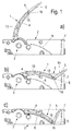
- each one shown in a furniture body, not shown ejector is shown with a contact surface 10 having ejection lever 1, which is mounted on a support member 2 from a non-use position swung out into a use position, wherein the contact surface 10 seen in the swivel direction is convexly curved and in functional position is supported on a rear wall of a drawer, for example, which is to be pushed by the ejector a piece far from the furniture body.
- the pivoting of the ejection lever 1 is usually carried out by means of an electric drive, not shown.
- the ejection lever 1 consists of a lever arm 4 connected to the rotary bearing 3 and an associated extension leg 5 which can be bent in the swiveling-out direction of the ejection lever 1.
- the ejection lever 1 has reached an end position in which the adjacent drawer is ejected by a maximum distance.
- the extension leg 5 When pivoting back into a pivoted non-use position, the extension leg 5 initially applies to a stop 7 of the support member 2 and kinks in the swivel direction until the lever arm 4 comes to rest on a support 6 of the support member 2.
- a leg spring 9 is provided, which is supported with a leg 11 on the lever arm 4 and with the other leg 11 on the extension leg 5, while a spring eye 12 on a pivot pin 13, which acts as a pivot bearing is plugged.
- a support surface 15 is integrally formed on the lever arm 4, in the aligned position a support edge 16 of the extension leg 5 as a barrier, so that a further rotation of Extension leg 5 is excluded.
- the extension leg 5 is formed Imgliedrig and consists of hingedly interconnected lever members 14, one of which is connected to the first lever arm 4 in the sense of the invention, as the other lever members 14 to each other. That is, the lever members 14 are all in the swiveling out of the ejection lever 1 bendable on the adjacent lever member 14 or articulated on the lever arm 4.
- the Verschwenkêt by a support surface in correspondence with a supporting edge 16 is realized in the lever members 14, as to the embodiment according to the FIG. 1 is described.
- the in the FIGS. 4 to 6 shown variant is characterized in particular by the fact that by the articulated connection of the lever members 14 with each other, which may be incidentally also spring-loaded, allows a very small depth of the ejector, wherein in the in the FIG. 5 shown example, the elongated lever members 14 abut the pad-like support 6, which simultaneously forms an outer surface, whereas the lever members 14 in the embodiment according to FIG. 6 are immersed in non-use position in the support member 2 and abut the wedge-shaped support 6.
Landscapes
- Engineering & Computer Science (AREA)
- Mechanical Engineering (AREA)
- Drawers Of Furniture (AREA)
- Pivots And Pivotal Connections (AREA)
Description
Die Erfindung betrifft eine in einen Möbelkorpus einbaubare Ausstoßeinrichtung nach dem Oberbegriff des Anspruchs 1.The invention relates to a device which can be installed in a furniture carcass according to the preamble of
Derartige Ausstoßeinrichtungen dienen dazu, beispielsweise einen in einem Führungsschienensystem in einem Möbelkorpus gelagerten Schubkasten ein Stück weit aus dem Möbelkorpus herauszudrücken, um so die Handhabung zu erleichtern.Such ejection devices serve, for example, to push out a piece of drawer mounted in a guide rail system in a furniture carcass to a certain extent out of the furniture carcass so as to facilitate handling.
Dabei soll die Ausstoßstrecke, also der wirksame, von seiner Baulänge abhängige Weg des Ausstoßhebels möglichst groß sein, wobei der Ausstoßhebel mit einer Anlagefläche, die im Übrigen üblicherweise in ihrer Längserstreckung konvex ausgebildet ist, an der Rückwand des Schubkastens anliegt.In this case, the ejection distance, so the effective, dependent on its length travel of the ejection lever should be as large as possible, wherein the ejection lever rests with a contact surface, which is usually convex in its longitudinal extent, on the rear wall of the drawer.
Die vor allem durch die eingesetzten Schubkästen bestimmten Platzverhältnisse sind jedoch sehr eingeschränkt und lassen eine Optimierung des Ausstoßhebels insbesondere hinsichtlich der Ausstoßstrecke nicht zu, vor allem dann nicht, wenn die Ausstoßeinrichtung standardisiert ist, d.h., wenn eine Ausstoßeinrichtung für alle zum Einsatz kommenden Schubkastenbreiten Verwendung finden soll.The particular determined by the used drawers space but are very limited and do not allow an optimization of the ejection lever, especially in terms of ejection distance, especially not if the ejector is standardized, ie, if an ejector for all coming into use drawer widths use should.
In diesem Fall ist das Längenmaß des Hebelarms abhängig von der Breite des schmalsten Schubkastens bzw. des entsprechenden Möbelkorpus, so dass lediglich eine relativ geringe Ausstoßstrecke realisierbar ist.In this case, the length dimension of the lever arm is dependent on the width of the narrowest drawer or the corresponding furniture body, so that only a relatively small discharge distance can be realized.
Um diesem Nachteil abzuhelfen, ist in der
Je nach Breite des Schubkastens muss also ein entsprechend angepasster Verlängerungsschenkel am Hebelarm angebracht werden, um den gewünschten Effekt einer größtmöglichen Ausstoßstrecke für den jeweiligen Schubkasten zu erreichen.Depending on the width of the drawer so a correspondingly adapted extension leg must be attached to the lever arm in order to achieve the desired effect of the largest possible discharge distance for the respective drawer.
In der Praxis führt dies dazu, dass eine bestimmte Anzahl unterschiedlich langer Verlängerungsschenkel bereitgehalten werden müssen, die dann, üblicherweise an Ort und Stelle der Montage, nach einer entsprechenden Auswahl mit dem Hebelarm verrastet werden.In practice, this means that a certain number of different lengths extension legs must be kept ready, which are then, usually in place of the assembly, after a corresponding selection with the lever arm locked.
Hinsichtlich der Herstellung, ebenso wie der Verwendbarkeit, stellt diese Konstruktion eine sehr unbefriedigende Lösung dar.With regard to the production, as well as the usability, this construction represents a very unsatisfactory solution.
Der Erfindung liegt die Aufgabe zugrunde, eine Ausstoßeinrichtung der gattungsgemäßen Art so weiterzuentwickeln, dass sie kostengünstiger herstellbar ist und in ihrer Verwendungsfähigkeit verbessert wird.The invention has for its object to further develop an ejector of the generic type so that it is cheaper to produce and is improved in their usefulness.
Diese Aufgabe wird durch eine Ausstoßeinrichtung mit den Merkmalen des Anspruchs 1 gelöst.This object is achieved by an ejection device having the features of
Die neue Ausstoßeinrichtung zeichnet sich zunächst einmal dadurch aus, dass sie für unterschiedlichste Schubkästenbreiten einen größtmöglichen Ausstoßweg ermöglicht, ohne dass die Ausstoßeinrichtung angepasst werden müsste.The new ejector is initially characterized by the fact that it allows for a wide variety of drawers widths a maximum discharge path, without the ejector would have to be adjusted.
Durch die Einknickung des Verlängerungsschenkels gegenüber dem Hebelarm in einer Nichtgebrauchsstellung, wird ein geringstmöglicher Platz beansprucht, der im Wesentlichen durch das üblicherweise als Gehäuse ausgebildete Tragteil definiert ist, wobei das Tragteil einen Anschlag aufweist, durch den der Verlängerungsschenkel beim Einschwenken des Ausstoßhebels gegenüber dem Hebelarm in Ausschwenkrichtung verdreht wird.The buckling of the extension leg relative to the lever arm in a non-use position, a minimum space is claimed, which is essentially defined by the usually formed as a housing support member, wherein the support member has a stop by which the extension leg when pivoting the ejection lever relative to the lever arm in Untwisting is twisted.
Bevorzugt ist der Verlängerungsschenkel entgegen der Knickrichtung federbelastet, wozu beispielsweise eine Schenkelfeder vorgesehen sein kann, deren einer Schenkel sich am Hebelarm und der andere Schenkel am Verlängerungsschenkel abstützt, während das Auge der Schenkelfeder an einem Gelenkzapfen eines Drehlagers gelagert ist, über das der Verlängerungsschenkel am Hebelarm drehbar ist.Preferably, the extension leg is spring-loaded against the buckling direction, including, for example, a leg spring may be provided, one leg is supported on the lever arm and the other leg on the extension leg, while the eye of the leg spring is mounted on a pivot pin of a pivot bearing on the extension leg on the lever arm is rotatable.
Durch die Schenkelfeder wird erreicht, dass sich der Verlängerungsschenkel gegenüber dem Hebelarm beim Aufschwenken des Ausstoßhebels in eine gestreckte Lage bewegt, bis der Verlängerungsschenkel an einer Barriere zur Anlage kommt, die ein Weiterdrehen des Verlängerungsschenkels verhindert. Diese Barriere kann durch entsprechende Formgebung im Verbindungsbereich zwischen dem Hebelarm und dem Verlängerungsschenkel geschaffen sein.By the leg spring is achieved that the extension leg relative to the lever arm during pivoting of the ejection lever in a stretched Position moves until the extension leg comes to a barrier to the plant, which prevents further rotation of the extension leg. This barrier can be created by appropriate shaping in the connection region between the lever arm and the extension leg.
Neben der verbesserten Verwendbarkeit der Ausstoßeinrichtung ist als weiterer Vorteil hervorzuheben, dass eine komplette Konfektionierung der Ausstoßeinrichtung für die gängigen Schubkastenbreiten bzw. Möbelkorpus-Breiten möglich ist. D.h., es ist werksseitig im Wesentlichen nur eine maßliche Ausführungsform herzustellen und lagermäßig vorzuhalten, die praktisch unverändert montiert werden kann. Eine Konfiguration am Ort der Montage ist somit nicht mehr erforderlich.In addition to the improved usability of the ejector is to emphasize as a further advantage that a complete assembly of the ejector for the usual drawer widths or furniture body widths is possible. In other words, it is essentially only possible to produce and store in stock a dimensional embodiment at the factory, which can be mounted virtually unchanged. A configuration at the place of assembly is therefore no longer necessary.
Naturgemäß führt dies zu einer durchaus bemerkenswerten Kostenreduzierung, sowohl bei der Herstellung wie auch bei der Lagerhaltung und bei der nachfolgenden Montage.Naturally, this leads to a quite remarkable cost reduction, both in the production as well as in warehousing and subsequent assembly.
Nach einem weiteren Gedanken der Erfindung ist vorgesehen, den Verlängerungsschenkel mehrgliedrig auszubilden, wobei jedes sozusagen Hebelglied für sich im Sinne der Erfindung in Ausschwenkrichtung des Ausstoßhebels einknickbar am benachbarten Hebelglied angelenkt ist.According to a further aspect of the invention, the extension leg is designed to be multi-membered, wherein each, as it were, lever member is pivotally hinged to the adjacent lever member in the direction of the invention in the pivoting-out direction of the ejection lever.
Je nach Erfordernis, also je nachdem wie die Platzverhältnisse im jeweiligen Tragteil vorliegen, ist die Anzahl der Hebelglieder zu bestimmen, so dass in jedem Fall eine optimale Anpassung auf einfachste Art und Weise möglich ist.Depending on the requirement, ie depending on how the space available in the respective support member, the number of lever members is to be determined, so that in each case an optimal adaptation in the simplest way possible.
Weitere vorteilhafte Ausbildungen der Erfindung sind in den Unteransprüchen gekennzeichnet.Further advantageous embodiments of the invention are characterized in the subclaims.
Ausführungsbeispiele der Erfindung werden nachfolgend anhand der beigefügten Zeichnungen beschrieben.Embodiments of the invention will be described below with reference to the accompanying drawings.
Es zeigen:
- Figur 1a) bis 1c)
- eine erfindungsgemäße Ausstoßeinrichtung in unterschiedlichen Stellungen, jeweils in einer Seitenansicht
Figur 2- die Ausstoßeinrichtung nach
Figur 1 Figur 3- die Ausstoßeinrichtung nach
Figur 1 Figur 4- ein weiteres Ausführungsbeispiel einer Ausstoßeinrichtung in einer schematischen Seitenansicht
Figuren 5 und 6- die Ausstoßeinrichtung nach der
Figur 4 Figur 7- eine Einzelheit der Ausstoßeinrichtung nach
Figur 4
- figure 1a) to 1c)
- an ejection device according to the invention in different positions, each in a side view
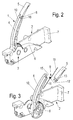
- FIG. 2
- the ejector after
FIG. 1 in a perspective view - FIG. 3
- the ejector after
FIG. 1 in an exploded view - FIG. 4
- a further embodiment of an ejection device in a schematic side view
- FIGS. 5 and 6
- the ejector after the
FIG. 4 , in each case in further embodiment variants, in a schematic side view - FIG. 7
- a detail of the ejector after
FIG. 4 in a perspective view.
In den
Der Ausstoßhebel 1 besteht aus einem am Drehlager 3 angeschlossenen Hebelarm 4 und einem damit verbundenen, in Ausschwenkrichtung des Ausstoßhebels 1 einknickbar angelenkten Verlängerungsschenkel 5.The
Bei dem in den
In dieser Position hat der Ausstoßhebel 1 eine Endposition erreicht, in der der anliegende Schubkasten um eine maximale Strecke ausgestoßen ist.In this position, the
Beim Zurückschwenken in eine eingeschwenkte Nichtgebrauchsstellung legt sich der Verlängerungsschenkel 5 zunächst an einen Anschlag 7 des Tragteiles 2 an und knickt dabei in Ausschwenkrichtung ein, bis der Hebelarm 4 an einem Auflager 6 des Tragteiles 2 zur Anlage kommt.When pivoting back into a pivoted non-use position, the
Wie deutlich zu erkennen ist, wird dadurch die Baulänge des Ausstoßhebels 1 in Nichtgebrauchsstellung deutlich verkürzt, wobei der dann praktisch zusammengeklappte Ausstoßhebel 1 nicht über die Projektionsfläche des Tragteiles 2, das als Gehäuse ausgebildet sein kann, hinausragt.As can be clearly seen, this significantly shortens the overall length of the
Um den Verlängerungsschenkel 5 selbsttätig beim Ausschwenken in eine mit dem Hebelarm 4 fluchtende Lage zu bringen, ist, wie in der
Zur Lagestabilisierung in dieser gestreckten Stellung, um den Verlängerungsschenkel 5 zu hindern, entgegen der Knickrichtung zu drehen, ist am Hebelarm 4 eine Stützfläche 15 angeformt, an der in fluchtender Stellung eine Stützkante 16 des Verlängerungsschenkels 5 als Barriere anliegt, so dass eine weitere Drehung des Verlängerungsschenkels 5 ausgeschlossen ist.To stabilize the position in this extended position to prevent the
In den
Die in den
Je nach Erfordernis kann die Anzahl der Hebelglieder 14 variieren. Denkbar ist jedoch auch, den Hebelarm 5 mit der Mehrzahl von Hebelgliedern 14 entsprechend der in der
- 11
- Ausstoßhebelejector lever
- 22
- Tragteilsupporting part
- 33
- Drehlagerpivot bearing
- 44
- Hebelarmlever arm
- 55
- Verlängerungsschenkelextension leg
- 66
- AuflagerIn stock
- 77
- Anschlagattack
- 88th
- Schwenklagerpivot bearing
- 99
- SchenkelfederLeg spring
- 1010
- Anlageflächecontact surface
- 1111
- Schenkelleg
- 1212
- Federaugespring eye
- 1313
- Schwenkzapfenpivot pin
- 1414
- Hebelgliedlever member
- 1515
- Stützflächesupport surface
- 1616
- Stützkantesupporting edge
Claims (10)
- An ejection device, comprising an ejection lever (1), which has a contact surface (10), and which is mounted on a support part (2) so it is pivotable out from a nonusage position into a usage position and consists in its longitudinal extension of a lever arm (4) attached to a pivot bearing (3) and an extension leg (5) connected thereto, characterized in that the extension leg (5) is linked on to the lever arm (4) so it can be buckled in the pivoting-out direction of the ejection lever (1).
- The ejection device according to Claim 1, characterized in that the extension leg (5) is held in a formfitting manner opposite to the buckling direction in the pivoted-out position.
- The ejection device according to Claim 1 or 2, characterized in that the extension leg (5) has a support edge (16), which presses against a support surface (15) of the lever arm (4) in the extended position of the lever arm (4) and the extension leg (5).
- The ejection device according to any one of the preceding claims, characterized in that the extension leg (5) can be buckled in a spring-loaded manner.
- The ejection device according to any one of the preceding claims, characterized in that at a pivot pin (13), by which the extension leg (5) is pivotably connected to the lever arm (4), a leg spring (9) is attached, one leg (11) of which is supported on the lever arm (4) and the other leg (11) is supported on the extension leg (5).
- The ejection device according to any one of the preceding claims, characterized in that the support part (2) has a stop (7), against which the extension leg (5) presses upon pivoting in of the ejection lever (1).
- The ejection device according to any one of the preceding claims, characterized in that the ejection lever (1) is located within the projected area of the support part (2) in the pivoted-in position.
- The ejection device according to any one of the preceding claims, characterized in that the extension leg (5) consists of at least two lever elements (14), which are articulated with one another so they can be buckled in the pivoted-out direction of the ejection lever (1).
- The ejection device according to any one of the preceding claims, characterized in that each lever element (14) has a support surface (15), against which a support edge (16) of the adjacent lever element (14) presses in the pivoted-out position of the ejection lever (1).
- The ejection device according to any one of the preceding claims, characterized in that the lever elements (14) can be buckled in a spring-loaded manner.
Applications Claiming Priority (2)
| Application Number | Priority Date | Filing Date | Title |
|---|---|---|---|
| DE202008010547U DE202008010547U1 (en) | 2008-08-08 | 2008-08-08 | Can be installed in a furniture carcass ejector |
| PCT/EP2009/059435 WO2010015513A1 (en) | 2008-08-08 | 2009-07-22 | Ejection device that can be installed in a furniture member |
Publications (2)
| Publication Number | Publication Date |
|---|---|
| EP2344005A1 EP2344005A1 (en) | 2011-07-20 |
| EP2344005B1 true EP2344005B1 (en) | 2016-09-07 |
Family
ID=41168612
Family Applications (1)
| Application Number | Title | Priority Date | Filing Date |
|---|---|---|---|
| EP09780934.7A Active EP2344005B1 (en) | 2008-08-08 | 2009-07-22 | Ejection device that can be installed in a furniture member |
Country Status (4)
| Country | Link |
|---|---|
| EP (1) | EP2344005B1 (en) |
| DE (1) | DE202008010547U1 (en) |
| ES (1) | ES2606235T3 (en) |
| WO (1) | WO2010015513A1 (en) |
Families Citing this family (6)
| Publication number | Priority date | Publication date | Assignee | Title |
|---|---|---|---|---|
| DE102009030668A1 (en) * | 2009-06-25 | 2010-12-30 | Grass Gmbh | Device for ejecting a furniture part and furniture |
| AT509702B1 (en) * | 2010-04-19 | 2011-11-15 | Blum Gmbh Julius | EXTRACTOR FOR EJECTING A MOVABLE FURNITURE PART |
| DE102010016608A1 (en) | 2010-04-23 | 2011-10-27 | Paul Hettich Gmbh & Co. Kg | ejector |
| DE202010009794U1 (en) * | 2010-07-02 | 2011-11-08 | Grass Gmbh | Device with a power storage and a movably mounted opening element and furniture |
| DE202011004477U1 (en) * | 2011-03-28 | 2014-07-28 | Grass Gmbh | Furniture, device for influencing the movement of a furniture part and device for locking an element |
| DE202014102730U1 (en) * | 2014-06-12 | 2015-09-15 | Grass Gmbh | Device for ejecting a furniture part and furniture |
Family Cites Families (7)
| Publication number | Priority date | Publication date | Assignee | Title |
|---|---|---|---|---|
| BE514030A (en) * | ||||
| JP3906813B2 (en) * | 2003-02-19 | 2007-04-18 | 松下電工株式会社 | Pull-out device for drawer |
| TWM284151U (en) * | 2005-09-08 | 2005-12-21 | Jarllytec Co Ltd | Sliding component |
| AT503139B1 (en) * | 2006-02-08 | 2009-02-15 | Blum Gmbh Julius | OUTBOARD WITH SLIP COUPLING |
| DE202006006190U1 (en) * | 2006-04-18 | 2007-08-30 | Paul Hettich Gmbh & Co. Kg | Furniture, has drawer that is pre-stressed from easily opened position into closed position by using self-closure, where self-closure is provided with ejector mechanism to move drawer into opened position |
| DE202006011039U1 (en) * | 2006-07-14 | 2007-12-06 | Alfit Ag | Device for moving furniture parts and furniture that are movable relative to one another |
| AT504765B1 (en) * | 2007-02-01 | 2012-04-15 | Blum Gmbh Julius | EJECTOR LEVER FOR AN EJECTOR |
-
2008
- 2008-08-08 DE DE202008010547U patent/DE202008010547U1/en not_active Expired - Lifetime
-
2009
- 2009-07-22 EP EP09780934.7A patent/EP2344005B1/en active Active
- 2009-07-22 ES ES09780934.7T patent/ES2606235T3/en active Active
- 2009-07-22 WO PCT/EP2009/059435 patent/WO2010015513A1/en active Application Filing
Also Published As
| Publication number | Publication date |
|---|---|
| EP2344005A1 (en) | 2011-07-20 |
| ES2606235T3 (en) | 2017-03-23 |
| WO2010015513A1 (en) | 2010-02-11 |
| DE202008010547U1 (en) | 2009-12-17 |
Similar Documents
| Publication | Publication Date | Title |
|---|---|---|
| EP2344005B1 (en) | Ejection device that can be installed in a furniture member | |
| DE4342400C2 (en) | Rollover bar device | |
| DE102009011858B4 (en) | Sliding door with extended travel and with hinged roller bracket | |
| EP2036771B1 (en) | Protection device for the interior of a motor vehicle and guide assembly for the same | |
| DE202008000596U1 (en) | blade assembly | |
| DE102004006873B3 (en) | Automobile passenger seat with active headrest supported from backrest frame and locked in deployed position via a spring-loaded blocking device | |
| EP2977267B1 (en) | Load carrier for motor vehicles, in particular in the form of a roof rack | |
| EP2531074B1 (en) | Drawer having a divider system | |
| EP1808342A2 (en) | Protection device for a vehicle. | |
| DE202018101158U1 (en) | Adjustment device for a headrest | |
| EP2730734B1 (en) | Bidirectional retraction device for a middle sliding door | |
| DE2601152A1 (en) | ELECTRIC DRY SHAVER | |
| EP2871981B1 (en) | Device for stuffing cigarette tubes | |
| EP0966374A1 (en) | Support for the joint hinge of a wiper blade | |
| EP3296492A1 (en) | Guide system for a push door and push door with a guide system and motor vehicle with corresponding feature | |
| DE4126085A1 (en) | Support stand for trailer caravan - uses selectively displaceable connecting rod and winding mechanism | |
| DE10253186B4 (en) | folding seat | |
| DE19931953A1 (en) | Mounting for end of slat on longitudinal strut in frame comprises base mounting attached to longitudinal strut, slide attached to this and to support for slat, and locking device including movable clip which fits free side of mounting | |
| EP2057918B1 (en) | Changeable upholstery combination with a sliding element | |
| EP1817981B1 (en) | Device for guiding the movement of movable furniture parts relative to one another, in particular for drawer guides, aswell as a drawer guide with such a device. | |
| DE102017121385A1 (en) | Mirrors and drawer | |
| DE10231670A1 (en) | Cup holder, especially for a dashboard in a vehicle | |
| AT13451U1 (en) | Bridge between two articulated vehicle parts | |
| DE102017110499A1 (en) | Lifting mechanism with a shelf, furniture and drawer | |
| EP3626538B1 (en) | Console device for a commercial vehicle cabin |
Legal Events
| Date | Code | Title | Description |
|---|---|---|---|
| PUAI | Public reference made under article 153(3) epc to a published international application that has entered the european phase |
Free format text: ORIGINAL CODE: 0009012 |
|
| 17P | Request for examination filed |
Effective date: 20110224 |
|
| AK | Designated contracting states |
Kind code of ref document: A1 Designated state(s): AT BE BG CH CY CZ DE DK EE ES FI FR GB GR HR HU IE IS IT LI LT LU LV MC MK MT NL NO PL PT RO SE SI SK SM TR |
|
| AX | Request for extension of the european patent |
Extension state: AL BA RS |
|
| DAX | Request for extension of the european patent (deleted) | ||
| GRAP | Despatch of communication of intention to grant a patent |
Free format text: ORIGINAL CODE: EPIDOSNIGR1 |
|
| INTG | Intention to grant announced |
Effective date: 20160418 |
|
| GRAS | Grant fee paid |
Free format text: ORIGINAL CODE: EPIDOSNIGR3 |
|
| GRAA | (expected) grant |
Free format text: ORIGINAL CODE: 0009210 |
|
| AK | Designated contracting states |
Kind code of ref document: B1 Designated state(s): AT BE BG CH CY CZ DE DK EE ES FI FR GB GR HR HU IE IS IT LI LT LU LV MC MK MT NL NO PL PT RO SE SI SK SM TR |
|
| REG | Reference to a national code |
Ref country code: GB Ref legal event code: FG4D Free format text: NOT ENGLISH |
|
| REG | Reference to a national code |
Ref country code: CH Ref legal event code: EP |
|
| REG | Reference to a national code |
Ref country code: IE Ref legal event code: FG4D Free format text: LANGUAGE OF EP DOCUMENT: GERMAN |
|
| REG | Reference to a national code |
Ref country code: DE Ref legal event code: R096 Ref document number: 502009013072 Country of ref document: DE |
|
| REG | Reference to a national code |
Ref country code: AT Ref legal event code: REF Ref document number: 826037 Country of ref document: AT Kind code of ref document: T Effective date: 20161015 |
|
| REG | Reference to a national code |
Ref country code: DE Ref legal event code: R079 Ref document number: 502009013072 Country of ref document: DE Free format text: PREVIOUS MAIN CLASS: A47B0088040000 Ipc: A47B0088400000 |
|
| REG | Reference to a national code |
Ref country code: LT Ref legal event code: MG4D |
|
| REG | Reference to a national code |
Ref country code: NL Ref legal event code: MP Effective date: 20160907 |
|
| PG25 | Lapsed in a contracting state [announced via postgrant information from national office to epo] |
Ref country code: LT Free format text: LAPSE BECAUSE OF FAILURE TO SUBMIT A TRANSLATION OF THE DESCRIPTION OR TO PAY THE FEE WITHIN THE PRESCRIBED TIME-LIMIT Effective date: 20160907 Ref country code: HR Free format text: LAPSE BECAUSE OF FAILURE TO SUBMIT A TRANSLATION OF THE DESCRIPTION OR TO PAY THE FEE WITHIN THE PRESCRIBED TIME-LIMIT Effective date: 20160907 Ref country code: FI Free format text: LAPSE BECAUSE OF FAILURE TO SUBMIT A TRANSLATION OF THE DESCRIPTION OR TO PAY THE FEE WITHIN THE PRESCRIBED TIME-LIMIT Effective date: 20160907 Ref country code: NO Free format text: LAPSE BECAUSE OF FAILURE TO SUBMIT A TRANSLATION OF THE DESCRIPTION OR TO PAY THE FEE WITHIN THE PRESCRIBED TIME-LIMIT Effective date: 20161207 |
|
| PG25 | Lapsed in a contracting state [announced via postgrant information from national office to epo] |
Ref country code: LV Free format text: LAPSE BECAUSE OF FAILURE TO SUBMIT A TRANSLATION OF THE DESCRIPTION OR TO PAY THE FEE WITHIN THE PRESCRIBED TIME-LIMIT Effective date: 20160907 Ref country code: GR Free format text: LAPSE BECAUSE OF FAILURE TO SUBMIT A TRANSLATION OF THE DESCRIPTION OR TO PAY THE FEE WITHIN THE PRESCRIBED TIME-LIMIT Effective date: 20161208 Ref country code: NL Free format text: LAPSE BECAUSE OF FAILURE TO SUBMIT A TRANSLATION OF THE DESCRIPTION OR TO PAY THE FEE WITHIN THE PRESCRIBED TIME-LIMIT Effective date: 20160907 Ref country code: SE Free format text: LAPSE BECAUSE OF FAILURE TO SUBMIT A TRANSLATION OF THE DESCRIPTION OR TO PAY THE FEE WITHIN THE PRESCRIBED TIME-LIMIT Effective date: 20160907 |
|
| PG25 | Lapsed in a contracting state [announced via postgrant information from national office to epo] |
Ref country code: RO Free format text: LAPSE BECAUSE OF FAILURE TO SUBMIT A TRANSLATION OF THE DESCRIPTION OR TO PAY THE FEE WITHIN THE PRESCRIBED TIME-LIMIT Effective date: 20160907 Ref country code: EE Free format text: LAPSE BECAUSE OF FAILURE TO SUBMIT A TRANSLATION OF THE DESCRIPTION OR TO PAY THE FEE WITHIN THE PRESCRIBED TIME-LIMIT Effective date: 20160907 |
|
| PG25 | Lapsed in a contracting state [announced via postgrant information from national office to epo] |
Ref country code: SK Free format text: LAPSE BECAUSE OF FAILURE TO SUBMIT A TRANSLATION OF THE DESCRIPTION OR TO PAY THE FEE WITHIN THE PRESCRIBED TIME-LIMIT Effective date: 20160907 Ref country code: IS Free format text: LAPSE BECAUSE OF FAILURE TO SUBMIT A TRANSLATION OF THE DESCRIPTION OR TO PAY THE FEE WITHIN THE PRESCRIBED TIME-LIMIT Effective date: 20170107 Ref country code: PT Free format text: LAPSE BECAUSE OF FAILURE TO SUBMIT A TRANSLATION OF THE DESCRIPTION OR TO PAY THE FEE WITHIN THE PRESCRIBED TIME-LIMIT Effective date: 20170109 Ref country code: SM Free format text: LAPSE BECAUSE OF FAILURE TO SUBMIT A TRANSLATION OF THE DESCRIPTION OR TO PAY THE FEE WITHIN THE PRESCRIBED TIME-LIMIT Effective date: 20160907 Ref country code: BG Free format text: LAPSE BECAUSE OF FAILURE TO SUBMIT A TRANSLATION OF THE DESCRIPTION OR TO PAY THE FEE WITHIN THE PRESCRIBED TIME-LIMIT Effective date: 20161207 Ref country code: CZ Free format text: LAPSE BECAUSE OF FAILURE TO SUBMIT A TRANSLATION OF THE DESCRIPTION OR TO PAY THE FEE WITHIN THE PRESCRIBED TIME-LIMIT Effective date: 20160907 Ref country code: PL Free format text: LAPSE BECAUSE OF FAILURE TO SUBMIT A TRANSLATION OF THE DESCRIPTION OR TO PAY THE FEE WITHIN THE PRESCRIBED TIME-LIMIT Effective date: 20160907 |
|
| REG | Reference to a national code |
Ref country code: DE Ref legal event code: R097 Ref document number: 502009013072 Country of ref document: DE |
|
| PLBE | No opposition filed within time limit |
Free format text: ORIGINAL CODE: 0009261 |
|
| STAA | Information on the status of an ep patent application or granted ep patent |
Free format text: STATUS: NO OPPOSITION FILED WITHIN TIME LIMIT |
|
| PG25 | Lapsed in a contracting state [announced via postgrant information from national office to epo] |
Ref country code: DK Free format text: LAPSE BECAUSE OF FAILURE TO SUBMIT A TRANSLATION OF THE DESCRIPTION OR TO PAY THE FEE WITHIN THE PRESCRIBED TIME-LIMIT Effective date: 20160907 |
|
| 26N | No opposition filed |
Effective date: 20170608 |
|
| PG25 | Lapsed in a contracting state [announced via postgrant information from national office to epo] |
Ref country code: SI Free format text: LAPSE BECAUSE OF FAILURE TO SUBMIT A TRANSLATION OF THE DESCRIPTION OR TO PAY THE FEE WITHIN THE PRESCRIBED TIME-LIMIT Effective date: 20160907 |
|
| REG | Reference to a national code |
Ref country code: CH Ref legal event code: PL |
|
| GBPC | Gb: european patent ceased through non-payment of renewal fee |
Effective date: 20170722 |
|
| REG | Reference to a national code |
Ref country code: IE Ref legal event code: MM4A |
|
| REG | Reference to a national code |
Ref country code: FR Ref legal event code: ST Effective date: 20180330 |
|
| PG25 | Lapsed in a contracting state [announced via postgrant information from national office to epo] |
Ref country code: GB Free format text: LAPSE BECAUSE OF NON-PAYMENT OF DUE FEES Effective date: 20170722 Ref country code: CH Free format text: LAPSE BECAUSE OF NON-PAYMENT OF DUE FEES Effective date: 20170731 Ref country code: IE Free format text: LAPSE BECAUSE OF NON-PAYMENT OF DUE FEES Effective date: 20170722 Ref country code: LI Free format text: LAPSE BECAUSE OF NON-PAYMENT OF DUE FEES Effective date: 20170731 |
|
| REG | Reference to a national code |
Ref country code: BE Ref legal event code: MM Effective date: 20170731 |
|
| PG25 | Lapsed in a contracting state [announced via postgrant information from national office to epo] |
Ref country code: FR Free format text: LAPSE BECAUSE OF NON-PAYMENT OF DUE FEES Effective date: 20170731 |
|
| PG25 | Lapsed in a contracting state [announced via postgrant information from national office to epo] |
Ref country code: LU Free format text: LAPSE BECAUSE OF NON-PAYMENT OF DUE FEES Effective date: 20170722 |
|
| PG25 | Lapsed in a contracting state [announced via postgrant information from national office to epo] |
Ref country code: BE Free format text: LAPSE BECAUSE OF NON-PAYMENT OF DUE FEES Effective date: 20170731 |
|
| PG25 | Lapsed in a contracting state [announced via postgrant information from national office to epo] |
Ref country code: MT Free format text: LAPSE BECAUSE OF FAILURE TO SUBMIT A TRANSLATION OF THE DESCRIPTION OR TO PAY THE FEE WITHIN THE PRESCRIBED TIME-LIMIT Effective date: 20160907 |
|
| PG25 | Lapsed in a contracting state [announced via postgrant information from national office to epo] |
Ref country code: MC Free format text: LAPSE BECAUSE OF FAILURE TO SUBMIT A TRANSLATION OF THE DESCRIPTION OR TO PAY THE FEE WITHIN THE PRESCRIBED TIME-LIMIT Effective date: 20160907 Ref country code: HU Free format text: LAPSE BECAUSE OF FAILURE TO SUBMIT A TRANSLATION OF THE DESCRIPTION OR TO PAY THE FEE WITHIN THE PRESCRIBED TIME-LIMIT; INVALID AB INITIO Effective date: 20090722 |
|
| PG25 | Lapsed in a contracting state [announced via postgrant information from national office to epo] |
Ref country code: CY Free format text: LAPSE BECAUSE OF NON-PAYMENT OF DUE FEES Effective date: 20160907 |
|
| PG25 | Lapsed in a contracting state [announced via postgrant information from national office to epo] |
Ref country code: MK Free format text: LAPSE BECAUSE OF FAILURE TO SUBMIT A TRANSLATION OF THE DESCRIPTION OR TO PAY THE FEE WITHIN THE PRESCRIBED TIME-LIMIT Effective date: 20160907 |
|
| PGFP | Annual fee paid to national office [announced via postgrant information from national office to epo] |
Ref country code: AT Payment date: 20210720 Year of fee payment: 13 Ref country code: IT Payment date: 20210730 Year of fee payment: 13 |
|
| PGFP | Annual fee paid to national office [announced via postgrant information from national office to epo] |
Ref country code: ES Payment date: 20210819 Year of fee payment: 13 Ref country code: TR Payment date: 20210713 Year of fee payment: 13 |
|
| REG | Reference to a national code |
Ref country code: DE Ref legal event code: R084 Ref document number: 502009013072 Country of ref document: DE |
|
| REG | Reference to a national code |
Ref country code: AT Ref legal event code: MM01 Ref document number: 826037 Country of ref document: AT Kind code of ref document: T Effective date: 20220722 |
|
| PG25 | Lapsed in a contracting state [announced via postgrant information from national office to epo] |
Ref country code: AT Free format text: LAPSE BECAUSE OF NON-PAYMENT OF DUE FEES Effective date: 20220722 |
|
| P01 | Opt-out of the competence of the unified patent court (upc) registered |
Effective date: 20230413 |
|
| PG25 | Lapsed in a contracting state [announced via postgrant information from national office to epo] |
Ref country code: IT Free format text: LAPSE BECAUSE OF NON-PAYMENT OF DUE FEES Effective date: 20220722 |
|
| REG | Reference to a national code |
Ref country code: ES Ref legal event code: FD2A Effective date: 20230830 |
|
| PG25 | Lapsed in a contracting state [announced via postgrant information from national office to epo] |
Ref country code: ES Free format text: LAPSE BECAUSE OF NON-PAYMENT OF DUE FEES Effective date: 20220723 |
|
| PGFP | Annual fee paid to national office [announced via postgrant information from national office to epo] |
Ref country code: DE Payment date: 20230720 Year of fee payment: 15 |