EP2343461A1 - Speed-up device for wind-driven generator and support mechanism for rotating shaft - Google Patents
Speed-up device for wind-driven generator and support mechanism for rotating shaft Download PDFInfo
- Publication number
- EP2343461A1 EP2343461A1 EP09815966A EP09815966A EP2343461A1 EP 2343461 A1 EP2343461 A1 EP 2343461A1 EP 09815966 A EP09815966 A EP 09815966A EP 09815966 A EP09815966 A EP 09815966A EP 2343461 A1 EP2343461 A1 EP 2343461A1
- Authority
- EP
- European Patent Office
- Prior art keywords
- bearing
- wind turbine
- gear box
- outer ring
- turbine generator
- Prior art date
- Legal status (The legal status is an assumption and is not a legal conclusion. Google has not performed a legal analysis and makes no representation as to the accuracy of the status listed.)
- Withdrawn
Links
Images



Classifications
-
- F—MECHANICAL ENGINEERING; LIGHTING; HEATING; WEAPONS; BLASTING
- F16—ENGINEERING ELEMENTS AND UNITS; GENERAL MEASURES FOR PRODUCING AND MAINTAINING EFFECTIVE FUNCTIONING OF MACHINES OR INSTALLATIONS; THERMAL INSULATION IN GENERAL
- F16C—SHAFTS; FLEXIBLE SHAFTS; ELEMENTS OR CRANKSHAFT MECHANISMS; ROTARY BODIES OTHER THAN GEARING ELEMENTS; BEARINGS
- F16C25/00—Bearings for exclusively rotary movement adjustable for wear or play
- F16C25/06—Ball or roller bearings
- F16C25/08—Ball or roller bearings self-adjusting
-
- F—MECHANICAL ENGINEERING; LIGHTING; HEATING; WEAPONS; BLASTING
- F03—MACHINES OR ENGINES FOR LIQUIDS; WIND, SPRING, OR WEIGHT MOTORS; PRODUCING MECHANICAL POWER OR A REACTIVE PROPULSIVE THRUST, NOT OTHERWISE PROVIDED FOR
- F03D—WIND MOTORS
- F03D15/00—Transmission of mechanical power
-
- F—MECHANICAL ENGINEERING; LIGHTING; HEATING; WEAPONS; BLASTING
- F03—MACHINES OR ENGINES FOR LIQUIDS; WIND, SPRING, OR WEIGHT MOTORS; PRODUCING MECHANICAL POWER OR A REACTIVE PROPULSIVE THRUST, NOT OTHERWISE PROVIDED FOR
- F03D—WIND MOTORS
- F03D80/00—Details, components or accessories not provided for in groups F03D1/00 - F03D17/00
- F03D80/70—Bearing or lubricating arrangements
-
- F—MECHANICAL ENGINEERING; LIGHTING; HEATING; WEAPONS; BLASTING
- F16—ENGINEERING ELEMENTS AND UNITS; GENERAL MEASURES FOR PRODUCING AND MAINTAINING EFFECTIVE FUNCTIONING OF MACHINES OR INSTALLATIONS; THERMAL INSULATION IN GENERAL
- F16C—SHAFTS; FLEXIBLE SHAFTS; ELEMENTS OR CRANKSHAFT MECHANISMS; ROTARY BODIES OTHER THAN GEARING ELEMENTS; BEARINGS
- F16C23/00—Bearings for exclusively rotary movement adjustable for aligning or positioning
- F16C23/06—Ball or roller bearings
- F16C23/08—Ball or roller bearings self-adjusting
-
- F—MECHANICAL ENGINEERING; LIGHTING; HEATING; WEAPONS; BLASTING
- F16—ENGINEERING ELEMENTS AND UNITS; GENERAL MEASURES FOR PRODUCING AND MAINTAINING EFFECTIVE FUNCTIONING OF MACHINES OR INSTALLATIONS; THERMAL INSULATION IN GENERAL
- F16C—SHAFTS; FLEXIBLE SHAFTS; ELEMENTS OR CRANKSHAFT MECHANISMS; ROTARY BODIES OTHER THAN GEARING ELEMENTS; BEARINGS
- F16C25/00—Bearings for exclusively rotary movement adjustable for wear or play
- F16C25/06—Ball or roller bearings
-
- F—MECHANICAL ENGINEERING; LIGHTING; HEATING; WEAPONS; BLASTING
- F16—ENGINEERING ELEMENTS AND UNITS; GENERAL MEASURES FOR PRODUCING AND MAINTAINING EFFECTIVE FUNCTIONING OF MACHINES OR INSTALLATIONS; THERMAL INSULATION IN GENERAL
- F16C—SHAFTS; FLEXIBLE SHAFTS; ELEMENTS OR CRANKSHAFT MECHANISMS; ROTARY BODIES OTHER THAN GEARING ELEMENTS; BEARINGS
- F16C35/00—Rigid support of bearing units; Housings, e.g. caps, covers
- F16C35/04—Rigid support of bearing units; Housings, e.g. caps, covers in the case of ball or roller bearings
- F16C35/06—Mounting or dismounting of ball or roller bearings; Fixing them onto shaft or in housing
- F16C35/063—Fixing them on the shaft
-
- F—MECHANICAL ENGINEERING; LIGHTING; HEATING; WEAPONS; BLASTING
- F16—ENGINEERING ELEMENTS AND UNITS; GENERAL MEASURES FOR PRODUCING AND MAINTAINING EFFECTIVE FUNCTIONING OF MACHINES OR INSTALLATIONS; THERMAL INSULATION IN GENERAL
- F16C—SHAFTS; FLEXIBLE SHAFTS; ELEMENTS OR CRANKSHAFT MECHANISMS; ROTARY BODIES OTHER THAN GEARING ELEMENTS; BEARINGS
- F16C35/00—Rigid support of bearing units; Housings, e.g. caps, covers
- F16C35/04—Rigid support of bearing units; Housings, e.g. caps, covers in the case of ball or roller bearings
- F16C35/06—Mounting or dismounting of ball or roller bearings; Fixing them onto shaft or in housing
- F16C35/07—Fixing them on the shaft or housing with interposition of an element
- F16C35/077—Fixing them on the shaft or housing with interposition of an element between housing and outer race ring
-
- F—MECHANICAL ENGINEERING; LIGHTING; HEATING; WEAPONS; BLASTING
- F16—ENGINEERING ELEMENTS AND UNITS; GENERAL MEASURES FOR PRODUCING AND MAINTAINING EFFECTIVE FUNCTIONING OF MACHINES OR INSTALLATIONS; THERMAL INSULATION IN GENERAL
- F16H—GEARING
- F16H37/00—Combinations of mechanical gearings, not provided for in groups F16H1/00 - F16H35/00
- F16H37/02—Combinations of mechanical gearings, not provided for in groups F16H1/00 - F16H35/00 comprising essentially only toothed or friction gearings
- F16H37/04—Combinations of toothed gearings only
- F16H37/041—Combinations of toothed gearings only for conveying rotary motion with constant gear ratio
-
- F—MECHANICAL ENGINEERING; LIGHTING; HEATING; WEAPONS; BLASTING
- F16—ENGINEERING ELEMENTS AND UNITS; GENERAL MEASURES FOR PRODUCING AND MAINTAINING EFFECTIVE FUNCTIONING OF MACHINES OR INSTALLATIONS; THERMAL INSULATION IN GENERAL
- F16H—GEARING
- F16H57/00—General details of gearing
- F16H57/02—Gearboxes; Mounting gearing therein
- F16H57/021—Shaft support structures, e.g. partition walls, bearing eyes, casing walls or covers with bearings
-
- F—MECHANICAL ENGINEERING; LIGHTING; HEATING; WEAPONS; BLASTING
- F05—INDEXING SCHEMES RELATING TO ENGINES OR PUMPS IN VARIOUS SUBCLASSES OF CLASSES F01-F04
- F05B—INDEXING SCHEME RELATING TO WIND, SPRING, WEIGHT, INERTIA OR LIKE MOTORS, TO MACHINES OR ENGINES FOR LIQUIDS COVERED BY SUBCLASSES F03B, F03D AND F03G
- F05B2240/00—Components
- F05B2240/50—Bearings
-
- F—MECHANICAL ENGINEERING; LIGHTING; HEATING; WEAPONS; BLASTING
- F05—INDEXING SCHEMES RELATING TO ENGINES OR PUMPS IN VARIOUS SUBCLASSES OF CLASSES F01-F04
- F05B—INDEXING SCHEME RELATING TO WIND, SPRING, WEIGHT, INERTIA OR LIKE MOTORS, TO MACHINES OR ENGINES FOR LIQUIDS COVERED BY SUBCLASSES F03B, F03D AND F03G
- F05B2260/00—Function
- F05B2260/40—Transmission of power
- F05B2260/403—Transmission of power through the shape of the drive components
- F05B2260/4031—Transmission of power through the shape of the drive components as in toothed gearing
- F05B2260/40311—Transmission of power through the shape of the drive components as in toothed gearing of the epicyclic, planetary or differential type
-
- F—MECHANICAL ENGINEERING; LIGHTING; HEATING; WEAPONS; BLASTING
- F16—ENGINEERING ELEMENTS AND UNITS; GENERAL MEASURES FOR PRODUCING AND MAINTAINING EFFECTIVE FUNCTIONING OF MACHINES OR INSTALLATIONS; THERMAL INSULATION IN GENERAL
- F16C—SHAFTS; FLEXIBLE SHAFTS; ELEMENTS OR CRANKSHAFT MECHANISMS; ROTARY BODIES OTHER THAN GEARING ELEMENTS; BEARINGS
- F16C2360/00—Engines or pumps
- F16C2360/31—Wind motors
-
- F—MECHANICAL ENGINEERING; LIGHTING; HEATING; WEAPONS; BLASTING
- F16—ENGINEERING ELEMENTS AND UNITS; GENERAL MEASURES FOR PRODUCING AND MAINTAINING EFFECTIVE FUNCTIONING OF MACHINES OR INSTALLATIONS; THERMAL INSULATION IN GENERAL
- F16C—SHAFTS; FLEXIBLE SHAFTS; ELEMENTS OR CRANKSHAFT MECHANISMS; ROTARY BODIES OTHER THAN GEARING ELEMENTS; BEARINGS
- F16C2361/00—Apparatus or articles in engineering in general
- F16C2361/61—Toothed gear systems, e.g. support of pinion shafts
-
- Y—GENERAL TAGGING OF NEW TECHNOLOGICAL DEVELOPMENTS; GENERAL TAGGING OF CROSS-SECTIONAL TECHNOLOGIES SPANNING OVER SEVERAL SECTIONS OF THE IPC; TECHNICAL SUBJECTS COVERED BY FORMER USPC CROSS-REFERENCE ART COLLECTIONS [XRACs] AND DIGESTS
- Y02—TECHNOLOGIES OR APPLICATIONS FOR MITIGATION OR ADAPTATION AGAINST CLIMATE CHANGE
- Y02E—REDUCTION OF GREENHOUSE GAS [GHG] EMISSIONS, RELATED TO ENERGY GENERATION, TRANSMISSION OR DISTRIBUTION
- Y02E10/00—Energy generation through renewable energy sources
- Y02E10/70—Wind energy
- Y02E10/72—Wind turbines with rotation axis in wind direction
Definitions
- the present invention relates to a gear box for a wind turbine generator and a supporting structure for a rotation shaft.
- a wind turbine generator includes a gear box for transmitting a rotation of a wind turbine to an electric generator after increasing a speed of the rotation of the wind turbine.
- a gear box there has been used a planetary gear box, in order to transmit larger torques and also to attain a higher speed-increasing ratio.
- roller bearings are frequently used as bearings for rotatably supporting speed-increasing gears, in order to support larger loads.
- the shaft is supported at its one end by a bearing which exerts binding forces both in an axial direction and radial directions and, also, is supported at the other end thereof by a bearing which exerts binding forces only in the radial directions while exerting no binding force in the axial direction.
- the wind turbine exerts an insufficient load on the bearings, which induces a state where there are smaller frictional forces (contact pressures) between outer rings, inner rings and rollers therebetween in the bearings, thereby facilitating the occurrence of slips therein.
- the present invention has been made in view of the above circumstance and an object thereof is to provide a gear box for a wind turbine generator and a supporting structure for a rotation shaft which are capable of suppressing the occurrence of slips in bearings with lower costs.
- a gear box for a wind turbine generator which increases a speed of rotation of a wind turbine
- the gear box includes step-up gears adapted such that the rotation of the wind turbine is transmitted thereto
- at least one of the step-up gears is rotatably supported at a rotation shaft thereof by at least two bearings
- at least one of the bearings includes a pre-load applying member adapted to partially press the bearing from outside for increasing a contact pressure between an outer ring supported by a casing of the gear box, an inner ring mounted on the rotation shaft, and a rolling element provided between the outer ring and the inner ring.
- the pre-load applying member partially presses the bearing from outside for increasing the contact pressure between the outer ring supported by the casing of the gear box, the inner ring mounted on the rotation shaft and the rolling element provided between the outer ring and the inner ring, it is possible to apply pre-load to this portion.
- pre-load By applying pre-load in this manner, it is possible to maintain a contact pressure, even when the contact pressure is reduced in low-load conditions, for example.
- the contact pressure between the outer ring and the inner ring and the rolling element can be maintained equal to or more than a certain value in both low-load conditions and high-load conditions, it is possible to suppress slips in the bearing.
- the pre-load applying member may be a sleeve which has a non-circular-shaped inner peripheral surface and is adapted such that the outer ring in the bearing is fitted therein.
- such a non-circular shape includes an elliptical shape, a triangular shape and the like and indicates a shape having a shorter diameter and a longer diameter which are different from each other.
- the sleeve may be constituted by two separated members which are separated in a circumferential direction. Accordingly, it is possible to easily form a sleeve having a non-circular-shaped inner peripheral surface.
- the pre-load applying member may be a screw member adapted to be inserted and extracted in a radial direction of the outer ring in the bearing.
- the pre-load applying member may include a pin adapted to be inserted and extracted in a radial direction of the outer ring in the bearing, and a driving source for driving the pin to insert and extract the pin.
- control portion adapted to cause the driving source to insert and extract the pin according to the rotation speed of the wind turbine.
- the rotation shaft may be provided with a tapered portion having a gradually increasing outer diameter
- the bearing may be provided by fitting the inner ring to the tapered portion
- a pressing screw for pressing the bearing in a direction of the increase of the outer diameter of the tapered portion may be provided as the pre-load applying member.
- the rolling element may have a hollow circular-cylindrical shape. Further, in the above aspect, the rolling element may be made of ceramic.
- the bearing may be adapted to bind the rotation shaft in radial directions and to allow the rotation shaft to be displaced in an axial direction.
- a circular-cylindrical roller bearing is preferably used as the bearing, but this tends to induce slips. Therefore, it is also possible to employ a tapered roller bearing or a ball bearing, such that the rear surface thereof is provided movably and slidably in the axial direction of the rotation shaft through rollers or balls.
- a rotation-shaft supporting structure including at least two bearings adapted to rotatably support a rotation shaft, wherein at least one of the bearings includes a pre-load applying member adapted to partially press the bearing from outside for increasing a contact pressure between an outer ring in the bearing, an inner ring mounted on the rotation shaft, and a rolling element provided between the outer ring and the inner ring.
- the pre-load applying member partially presses the bearing from outside for increasing the contact pressure between the outer ring, the inner ring mounted on the rotation shaft and the rolling element provided between the outer ring and the inner ring, it is possible to apply pre-load to this portion.
- pre-load By applying pre-load in this manner, it is possible to maintain a contact pressure, even when the contact pressure is reduced in low-load conditions, for example.
- the contact pressure between the outer ring and the inner ring and the rolling element can be maintained equal to or more than a certain value in both low-load conditions and high-load conditions, it is possible to suppress slips in the bearing.
- the bearing since the bearing is pressed from outside by the pre-load applying member, the bearing itself does not need to be subjected to specific processing which leads to high costs. This enables fabrication of the gear box with lower costs.
- the present invention it is possible to suppress slips of the bearing by pressing the bearing from outside, with the pre-load applying member, for increasing the contact pressure between the outer ring supported by the casing of the gear box, the inner ring mounted on the rotation shaft and the rolling element provided between the outer ring and the inner ring.
- the bearing since the bearing is pressed from outside, the bearing itself does not need to be subjected to specific processing. Therefore, the above effects can be obtained with lower costs, in comparison with cases of employing a non-circular shaped outer ring in the bearing.
- Fig. 1 is a block diagram illustrating the basic structure of the gear box 10 for a wind turbine generator according to the present embodiment. As illustrated in Fig.
- the gear box 10 includes an input shaft 11 coupled to a wind turbine which is not illustrated, a planetary pin 12a integrally coupled to the input shaft 11, a plurality of planetary gears 12 which are provided in the circumferential direction in a ring gear 11a and adapted to rotate through the mesh with the ring gear 11a, a sun gear 13 to which the rotations of the planetary gears 12 are transmitted after being increased in speed, a subsequent planetary pin 120a integrally coupled to the sun gear 13 through a coupling 15, a plurality of planetary gears 120 which are provided in the circumferential direction in a ring gear 110a and adapted to rotate through the mesh with the ring gear 110a, a sun shaft 14 to which the rotations of the planetary gears 120 are transmitted after being increased in speed, a parallel shaft 16 coupled to the sun shaft 14, and an output shaft (rotation shaft) 19 to which the rotation of the parallel shaft 16 is transmitted through gears (step-up gears) 17 and 18.
- Fig. 2 is an enlarged longitudinal cross-sectional view illustrating the structure of the portion of the gear 18 in Fig. 1 , in an enlarging manner.
- Fig. 3 is a lateral cross-sectional view of the same portion.
- the gear 18 in the last stage is provided integrally with the output shaft 19.
- the output shaft 19 is rotatably held in a casing 10a, through a first bearing (bearing) 20 which supports the output shaft 19 in the radial directions, and a second bearing (bearing) 21 which supports the output shaft 19 in the radial directions and the axial direction.
- the first bearing 20 is provided in the casing 10a with a sleeve 30 interposed therebetween.
- the sleeve 30 is formed to have an inside surface 30a having a non-circular shape, such as an elliptical shape or an oval shape, which has a longer diameter R1 and a shorter diameter R2 which are different from each other.
- the first bearing 20 has an outer ring 22 which is supported by the inside surface 30a of the sleeve (pre-load applying member) 30.
- the inside surface 30a is preferably adapted to have respective optimal values which are determined by the bearing size, the bearing load and the bearing rotation speed, for example, with respect to an outer diameter R of the outer ring 22.
- the outer ring 22 in the first bearing 20 is fitted to the Sleeve 30 through shrink fit.
- the outer ring 22 in the first bearing 20 is subjected to compressive loads in radial directions from the portions 31 and 31 of the sleeve 30 which have the shorter diameter R2. These compressive loads increase the contact pressures between the outer ring 22 and an inner ring 23 and rollers (rolling elements) 24 therebetween. That is, the sleeve 30 applies pre-load to the first bearing 20, thereby suppressing occurrences of slips of the rollers 24. As a result, it is possible to prevent damages and the like due to slips in the first bearing 20, when the output power of the wind turbine is small. Further, the above structure can be realized by processing the sleeve 30. Accordingly, it is possible to provide the above effects with lower costs, in comparison with a case of employing a non-circular-shaped outer ring 22 in the first bearing 20.
- the sleeve 30 having the elliptical-shaped inside surface 30a is formed to have an integral structure
- the sleeve 30 is not limited thereto.
- a sleeve 30 having a non-circular-shaped inside surface 30a can be also formed by integrally coupling semi-circular-shaped sleeve segments (separated members) 30A and 30B to each other, through bolts 32 and the like. In this case, as illustrated in Fig.
- the sleeve segments 30A and 30B can be formed by cutting away or removing, in parallel, portions of a circular-shaped member 33 at positions L2 and L3 offset by a certain dimension from a line L1 separating the member 33 into two parts.
- a gear box 10 according to a second embodiment of the present invention will be described with reference to Fig. 6 .
- the present embodiment is different from the first embodiment in the structure of the pre-load applying member and, therefore, will be described mainly with respect to the different portions, and descriptions of the portions same as those of the first embodiment will not be repeated. Further, the members same as those of the first embodiment will be designated by the same reference numerals.
- Fig. 6 is a lateral cross-sectional view illustrating the general structure of the pre-load applying member according to the present embodiment.
- a first bearing 20 is provided in a casing 10a with a sleeve 40 interposed therebetween.
- the sleeve 40 is provided with pre-load applying members 41 which apply compressive loads in radial directions to an outer ring 22 in the first bearing 20.
- pre-load applying members 41 which apply compressive loads in radial directions to an outer ring 22 in the first bearing 20.
- the pre-load applying members 41 are preferably provided in the periphery of sleeve 40 at substantially equal intervals.
- pre-load applying members 41 it is possible to employ screw members 41 having thread grooves formed in their outer peripheral portions, for example. Further, female threads 43 are formed in the sleeve 40, so that the screw member 42 can be screwed into the female threads 43, which enables inserting and extracting the screw members 42 in radial directions of the outer ring 22 in the first bearing 20. Further, by pushing the outer ring 22 with the tip end portions 41a of the pre-load applying members 41 (the screw members 42), it is possible to apply radial compressive loads to the outer ring 22 in the first bearing 20.
- the pre-load applying members 41 apply the compressive loads thereto, it is possible to increase the contact pressures between the outer ring 22 and an inner ring 23 and rollers (rolling elements) 24 therebetween, thereby suppressing the occurrence of slips of roller 24. As a result thereof, it is possible to prevent damages and the like due to slips in the first bearing 20, when the output power of the wind turbine is small. Further, this structure can be realized by processing the sleeve 30. Accordingly, it is possible to provide the above effects, with lower costs, in comparison with cases of employing a non-circular-shaped outer ring 22 in the first bearing 20.
- the pre-load applying members 41 can be constituted by pins 44, guide holes 45 can be formed in the sleeve 40 for enabling inserting and extracting the pins 44 thereinto and therefrom in radial directions of the outer ring 22 in the first bearing 20, and the pre-load applying members 41 can be inserted and extracted thereinto and therefrom in the above directions, with an insertion/extraction driving source (driving source), such as a hydraulic cylinder, which is not illustrated.
- driving source such as a hydraulic cylinder
- a gear box 10 according to a third embodiment of the present invention will be described with reference to Fig. 8 .
- the present embodiment is different from the first embodiment, in the structures of the pre-load applying members and the supporting structure for the rotation shaft 19 and, therefore, will be described mainly with respect to these different portions, and descriptions of the portions same as those of the first embodiment will not be repeated. Further, the members same as those of the first embodiment will be designated by the same reference numerals.
- Fig. 8 is a lateral cross-sectional view illustrating the general structure of the rotation shaft, according to the present embodiment.
- a first bearing 20 is constituted by roller bearings 50 capable of exerting binding forces in the radial directions and the axial direction, similarly to a second bearing 21, and there are provided, in a staggered manner, two roller bearings 50 each having an outer ring 51, an inner ring 52 and a plurality of tapered rollers 53 interposed between a tapered inner peripheral surface 51a of the outer ring 51 and a tapered outer peripheral surface 52a of the inner ring 52.
- the first bearing 20 is required to exert binding forces only in the radial directions, while allowing thermal expansion of the output shaft 19 in the axial direction. Accordingly, the first bearing 20 has the following structure. That is, the two roller bearings 50 are placed in a circular-cylindrical sleeve 54, and there are provided a plurality of balls 55 which enable the sleeve 54 to move in the direction of the axis of the output shaft 19, between the sleeve 54 and a casing 10a. This enables the first bearing 20 itself to move in the direction of the axis of the output shaft 19, thereby allowing thermal expansion of the output shaft 19.
- pre-load is applied to the first bearing 20 with a spring member 56, such as a coil spring, which is being compressed.
- a spring member 56 such as a coil spring
- the sleeve 54 is provided with a pre-load plate 57 which is opposed to a side surface 51b of an outer ring 51. Further, the spring member 56 being compressed is provided, between the pre-load plate 57 and the side surface 51b of the outer ring 51.
- the spring member 56 exerts a pressing force in the axial direction of the output shaft 19, on the side 51b of the outer ring 51.
- This causes the outer ring 51 to exert a load on the rollers 53 which are obliquely placed in two rows, thereby increasing the contact pressures between the outer rings 51 and the inner rings 52 and the rollers 53 therebetween. That is, the spring member 56 exerts pre-load on the first bearing 20, thereby suppressing the occurrence of slips of the rollers 53.
- the first bearing 20 is not limited to the roller bearings 50 illustrated in Fig. 8 , and as illustrated in Fig. 9 , it is also possible to employ ball bearings 60 including balls (rolling elements) 61 as the first bearing 20. Further, the same structures as those of the third embodiment will be designated by the same reference numerals and will not be described. In this case, a plurality of balls 61 having a contact angle are interposed in each of the angular ball bearings 60. Two angular ball bearings 60 are combined in a staggered manner to constitute the first bearing 20. This enables the first bearing 20 to exert binding forces not only in the radial directions but also in the axial direction.
- pre-load is applied to the first bearing 20 with a spring member 56 such as a coil spring which is being compressed, similarly to the structure illustrated in Fig. 7 .
- a spring member 56 such as a coil spring which is being compressed, similarly to the structure illustrated in Fig. 7 .
- a spring member 56 such as a coil spring which is being compressed, similarly to the structure illustrated in Fig. 7 .
- the rollers 65 have axes parallel to the output shaft 19, and a plurality of such rollers 65 are placed with intervals interposed therebetween in the circumferential direction, between the sleeve 54 and the casing 10a.
- rollers 65 come into line-to-line contact with the sleeve 54 in the axial direction of the output shaft 19. Therefore, as compared to cases of surface-to-surface contact, the rollers 65 can easily move in the axial direction of the output shaft 19, thereby allowing thermal expansion of the output shat 19.
- a gear box 10 according to a fourth embodiment of the present invention will be described with reference to Fig. 10 .
- the present embodiment is different from the first embodiment, in the structure of the pre-load applying member and, therefore, will be described mainly with respect to the different portion, and descriptions of the portions same as those of the first embodiment will not be repeated. Further, the members same as those of the first embodiment will be designated by the same reference numerals.
- Fig. 10 is a lateral cross-sectional view illustrating the general structure of the pre-load applying member, according to the present embodiment.
- the outer peripheral surface of the output shaft 19 forms a tapered portion 70 having a diameter gradually increased from its end portion, at its portion carrying a first bearing 20.
- the inner peripheral surface 71a of an inner ring 71 has a tapered shape conforming to the tapered portion 70.
- the output shaft 19 is formed with a spiral-shaped thread groove 72 in the outer peripheral surface of its end portion.
- a nut (pressing screw) 73 is screwed into the thread groove 72, so that the nut 73 fixes the first bearing 20 at a state where it is pressed from a smaller-diameter portion of the tapered portion 70 toward a larger-diameter portion thereof.
- the output shaft 19 has the tapered-shaped outer peripheral surface which is opposed to the inner peripheral surface of the inner ring 71, depending on the position thereof, the inner ring 71 elastically deforms in such a direction as to increase its diameter.
- the outer diameter of the inner ring 71 is changed uniformly in the circumferential direction by the tapered portion 70, pre-load is uniformly applied to the rollers 24, and heat generation due to friction caused by rolling of the rollers 24 is also suppressed. Further, it is possible to easily perform fine adjustment of the amount of pre-load, by adjusting the amount of screwing of the nut 73. This enables adjusting the amount of pre-load to an amount which suppresses the occurrence of slips and heat generation.
- the rollers 24 placed between the outer ring 22 and the outer ring 23 in the first bearing 20 can be replaced with rollers (rolling elements) 80 each having a hollow circular-cylindrical shape with a through hole 81 formed at its center portion, instead of a common circular-cylindrical shape, as illustrated in Fig. 11 .
- the rollers 24 and 80 can be made of ceramics, instead of common steels. In this manner, it is possible to reduce the weights of the rollers 24 and 80, which can reduce the rolling resistance when the rollers 24 and 80 are rolled. This can effectively suppress the occurrence of slips in the first bearing 20, either when smaller pre-load is applied thereto or when the output power is lower.
- the output shaft 19 is formed with an oil flow channel 90 extending in the direction of its center axis and, further, is formed with oil supply channels 91 and 92 extending from the oil flow channel 90 toward the inner ring 23 in the first bearing 20 and toward the inner ring 27 in the second bearing 21, respectively. Further, the oil flow channel 90 is supplied with oil, from an oil supply means which is not illustrated.
- the inner ring 23 in the first bearing 20 and the inner ring 27 in the second bearing 21 are provided with communication flow channels 93 and 94 which communicates to the oil supply channels 91 and 92, respectively.
- the communication flow channel 94 is formed between the two rows of the rollers 28. Accordingly, lubricant oil can be supplied to the rollers 24 and 28 at their sides near the inner ring 23 in the first bearing 20 and the inner ring 27 in the second bearing 21, through the oil flow channel 90, the oil supply channels 91 and 92, and the communication flow channels 93 and 94.
- oil supply channels 95 and 96 in the oil flow channel 90 in the output shaft 19. This enables lubricating and cooling the gear 18.
- the structures other than the gear boxes 10 are not restricted.
- the structures other than the first bearing 20 and the second bearing 21 for supporting the output shaft 19 are not restricted and can have any structures.
- the structures described in the above embodiments can be similarly applied to portions other than the output shaft 19 in the gear box 10. More specifically, the structures described in the above embodiments can be also employed as supporting structures for rotation shafts other than those of the gear boxes 10.
Landscapes
- Engineering & Computer Science (AREA)
- General Engineering & Computer Science (AREA)
- Mechanical Engineering (AREA)
- Sustainable Energy (AREA)
- Chemical & Material Sciences (AREA)
- Combustion & Propulsion (AREA)
- Life Sciences & Earth Sciences (AREA)
- Sustainable Development (AREA)
- Wind Motors (AREA)
- Rolling Contact Bearings (AREA)
- Support Of The Bearing (AREA)
- Mounting Of Bearings Or Others (AREA)
- General Details Of Gearings (AREA)
Abstract
Description
- The present invention relates to a gear box for a wind turbine generator and a supporting structure for a rotation shaft.
- A wind turbine generator includes a gear box for transmitting a rotation of a wind turbine to an electric generator after increasing a speed of the rotation of the wind turbine.
As such a gear box, there has been used a planetary gear box, in order to transmit larger torques and also to attain a higher speed-increasing ratio. In the planetary gear box, roller bearings are frequently used as bearings for rotatably supporting speed-increasing gears, in order to support larger loads. - As the bearing for the speed-increasing gear in the last stage, among the bearings included in a gear box, in order to allow thermal expansion of the shaft of the speed-increasing gear, the shaft is supported at its one end by a bearing which exerts binding forces both in an axial direction and radial directions and, also, is supported at the other end thereof by a bearing which exerts binding forces only in the radial directions while exerting no binding force in the axial direction.
- In recent years, along with increases in size of wind turbines in wind turbine generators, there have been raised concerns about occurrence of slips in the bearings in gear boxes, particularly in the bearings for the speed-increasing gears in the last stages therein under low-load condition. If slips occur in bearings, this will induce heat generation due to friction, thereby inducing damages and the like in the bearings.
When a wind turbine grows in size, the bearings therein should neeessarily have larger sizes corresponding to larger torques inputted thereto. Thus, when the output power of the wind turbine is small, the wind turbine exerts an insufficient load on the bearings, which induces a state where there are smaller frictional forces (contact pressures) between outer rings, inner rings and rollers therebetween in the bearings, thereby facilitating the occurrence of slips therein. - To cope therewith, as structures of such bearings, there have been suggested techniques for forming an outer ring to have an inner peripheral surface having an elliptical shape as a non-circular shape, in order to generate pre-load between the outer ring, the inner ring and the rollers. By employing these techniques, it is possible to effectively overcome the above problem (refer to Patent Citation 1 and 2, for example).
-
- Patent Citation 1:
- The Publication of Japanese Patent No.
2961983
- The Publication of Japanese Patent No.
- Patent Citation 2:
- Japanese Unexamined Patent Application, Publication No.
2001-304274
- Japanese Unexamined Patent Application, Publication No.
- However, in order to form a bearing including an outer ring with a non-circular-shaped inner peripheral surface, it is necessary to perform specific processing thereon with higher costs, since such a bearing is a component with a high degree of precision. As a matter of course, there has been generally a need for reduction of the costs for wind turbine generators. In view of this fact, the bearings having outer rings with non-circular-shaped inner peripheral surfaces cannot be easily employed.
- The present invention has been made in view of the above circumstance and an object thereof is to provide a gear box for a wind turbine generator and a supporting structure for a rotation shaft which are capable of suppressing the occurrence of slips in bearings with lower costs.
- In order to solve the above problem, the present invention adopts the following means.
That is, according to a first aspect of the present invention, there is provided a gear box for a wind turbine generator which increases a speed of rotation of a wind turbine, and the gear box includes step-up gears adapted such that the rotation of the wind turbine is transmitted thereto, wherein at least one of the step-up gears is rotatably supported at a rotation shaft thereof by at least two bearings, and at least one of the bearings includes a pre-load applying member adapted to partially press the bearing from outside for increasing a contact pressure between an outer ring supported by a casing of the gear box, an inner ring mounted on the rotation shaft, and a rolling element provided between the outer ring and the inner ring. - Since the pre-load applying member partially presses the bearing from outside for increasing the contact pressure between the outer ring supported by the casing of the gear box, the inner ring mounted on the rotation shaft and the rolling element provided between the outer ring and the inner ring, it is possible to apply pre-load to this portion. By applying pre-load in this manner, it is possible to maintain a contact pressure, even when the contact pressure is reduced in low-load conditions, for example. Thus, since the contact pressure between the outer ring and the inner ring and the rolling element can be maintained equal to or more than a certain value in both low-load conditions and high-load conditions, it is possible to suppress slips in the bearing. As a result, it is possible to prevent damages and the like due to slips of the bearing, even when the output power of the wind turbine is small.
Further, since the bearing is pressed from outside by the pre-load applying member, the bearing itself does not need to be subjected to specific processing which leads to high costs. This enables fabrication of the gear box with lower costs. - Further, in the above aspect, the pre-load applying member may be a sleeve which has a non-circular-shaped inner peripheral surface and is adapted such that the outer ring in the bearing is fitted therein.
- When the sleeve is formed to have a shorter-diameter portion with a diameter smaller than the diameter of the outer ring, it is possible to press the outer ring in the bearing in radial directions, which can increase the contact pressures between the outer ring and the inner ring and the rolling element.
Further, in this case, such a non-circular shape includes an elliptical shape, a triangular shape and the like and indicates a shape having a shorter diameter and a longer diameter which are different from each other. - In the above structure, the sleeve may be constituted by two separated members which are separated in a circumferential direction.
Accordingly, it is possible to easily form a sleeve having a non-circular-shaped inner peripheral surface. - In the above aspect, the pre-load applying member may be a screw member adapted to be inserted and extracted in a radial direction of the outer ring in the bearing.
- Accordingly, it is possible to press the outer ring in the bearing in the radial direction with the tip end portion of the screw member, thereby increasing the contact pressures between the outer ring and the inner ring and the rolling element.
Further, by inserting and extracting the screw member, it is possible to adjust the contact pressures. - In the above aspect, the pre-load applying member may include a pin adapted to be inserted and extracted in a radial direction of the outer ring in the bearing, and a driving source for driving the pin to insert and extract the pin.
- Accordingly, it is possible to press the outer ring in the bearing in the radial direction with the tip end portion of the pin which is inserted and extracted by the driving source, thereby increasing the contact pressures between the outer ring and the inner ring and the rolling element.
Further, by inserting and extracting the pin, it is possible to adjust the contact pressures. - In the above structure, there may be further provided a control portion adapted to cause the driving source to insert and extract the pin according to the rotation speed of the wind turbine.
- Thus, for example, when the output power of the wind turbine is small, it is possible to press the outer ring in the bearing in the radial direction with the tip end portion of the pin for increasing the contact pressures between the outer ring and the inner ring and the rolling element. When the wind turbine is in a rated operation condition, it is possible to retract the pin from the outer ring in the bearing, thereby reducing the pressing force.
- In the above aspect, the rotation shaft may be provided with a tapered portion having a gradually increasing outer diameter, the bearing may be provided by fitting the inner ring to the tapered portion, and a pressing screw for pressing the bearing in a direction of the increase of the outer diameter of the tapered portion may be provided as the pre-load applying member.
- By pressing the bearing, with the pressing screw, in the direction of the increase of the outer diameter of the tapered portion for deforming and enlarging the inner ring, it is possible to increase the contact pressures between the outer ring and the inner ring and the rolling element.
- In the above aspect, the rolling element may have a hollow circular-cylindrical shape.
Further, in the above aspect, the rolling element may be made of ceramic. - Accordingly, it is possible to reduce the weight of the rolling element, which can reduce the rolling resistance of the rolling element. This can effectively suppress slips of the rolling element, even when the pre-load applying member does not apply large pre-load to the rolling element.
- In the above aspect, the bearing may be adapted to bind the rotation shaft in radial directions and to allow the rotation shaft to be displaced in an axial direction.
- Thus, a circular-cylindrical roller bearing is preferably used as the bearing, but this tends to induce slips. Therefore, it is also possible to employ a tapered roller bearing or a ball bearing, such that the rear surface thereof is provided movably and slidably in the axial direction of the rotation shaft through rollers or balls.
- Further, according to a second aspect of the present invention, there is provided a rotation-shaft supporting structure including at least two bearings adapted to rotatably support a rotation shaft, wherein at least one of the bearings includes a pre-load applying member adapted to partially press the bearing from outside for increasing a contact pressure between an outer ring in the bearing, an inner ring mounted on the rotation shaft, and a rolling element provided between the outer ring and the inner ring.
- Since the pre-load applying member partially presses the bearing from outside for increasing the contact pressure between the outer ring, the inner ring mounted on the rotation shaft and the rolling element provided between the outer ring and the inner ring, it is possible to apply pre-load to this portion. By applying pre-load in this manner, it is possible to maintain a contact pressure, even when the contact pressure is reduced in low-load conditions, for example. Thus, since the contact pressure between the outer ring and the inner ring and the rolling element can be maintained equal to or more than a certain value in both low-load conditions and high-load conditions, it is possible to suppress slips in the bearing.
Further, since the bearing is pressed from outside by the pre-load applying member, the bearing itself does not need to be subjected to specific processing which leads to high costs. This enables fabrication of the gear box with lower costs. - According to the present invention, it is possible to suppress slips of the bearing by pressing the bearing from outside, with the pre-load applying member, for increasing the contact pressure between the outer ring supported by the casing of the gear box, the inner ring mounted on the rotation shaft and the rolling element provided between the outer ring and the inner ring. As a result, it is possible to prevent damages and the like due to slips of the bearing, even when the output power of the wind turbine is small.
Further, since the bearing is pressed from outside, the bearing itself does not need to be subjected to specific processing. Therefore, the above effects can be obtained with lower costs, in comparison with cases of employing a non-circular shaped outer ring in the bearing. -
- [
FIG. 1 ] A block diagram illustrating a gear box for a wind turbine generator according to a first embodiment of the present invention. - [
Fig. 2 ] A partial longitudinal cross-sectional view illustrating, in an enlarging manner, a supporting structure for an output shaft in the last stage in the gear box inFig. 1 . - [
Fig. 3 ] A lateral cross-sectional view illustrating a pre-load applying member according to the first embodiment of the present invention. - [
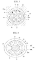
Fig. 4 ] A lateral cross-sectional view illustrating another embodiment of the pre-load applying member according to the present embodiment. - [
Fig. 5 ] A lateral cross-sectional view illustrating yet another embodiment of the pre-load applying member according to the present embodiment. - [
Fig. 6 ] A lateral cross-sectional view illustrating a pre-load applying member according to a second embodiment of the present invention. - [
Fig. 7 ] A lateral cross-sectional view illustrating another embodiment of the pre-load applying member according to the present embodiment. - [
Fig. 8 ] A lateral cross-sectional view illustrating a pre-load applying member according to a third embodiment of the present invention. - [
Fig. 9 ] A lateral cross-sectional view illustrating another embodiment of the pre-load applying member according to the present embodiment. - [
Fig. 10 ] A lateral cross-sectional view illustrating a pre-load applying member according to a fourth embodiment of the present invention. - [
Fig. 11 ] A perspective view illustrating a hollow roller. - [
Fig. 12 ] A longitudinal cross-sectional view illustrating an example of a lubrication system for a bearing according to the present embodiment. -
- 10: Gear box
- 10a: Casing
- 11: Input shaft
- 18: Gear
- 19: Output shaft (rotation shaft)
- 20: First bearing (bearing)
- 21: Second bearing (bearing)
- 22 and 29: Outer ring
- 23 and 27: Inner ring
- 24 and 28: Roller (rolling element)
- 30: Sleeve
- 30a: Inside surface
- 30A and 30B: Sleeve segment (separated member)
- 40: Sleeve
- 41: Pre-load applying member
- 41a: Tip end portion
- 42: Screw member
- 43: Female thread
- 44: Pin
- 45: Guide hole
- 50: Roller bearing
- 54: Sleeve
- 55: Ball
- 56: Spring member
- 57: Pre-load plate
- 60: Ball bearing
- 61: Ball (rolling element)
- 65: Roller
- 70: Tapered portion
- 71: Inner ring
- 73: Nut (pressing screw)
- 80: Roller (rolling element)
- 81: Through hole
- Hereinafter, embodiments of the present invention will be described with reference to the drawings.
- A
gear box 10 according to a first embodiment of the present invention will be described with reference toFigs. 1 to 3 .
Fig. 1 is a block diagram illustrating the basic structure of thegear box 10 for a wind turbine generator according to the present embodiment. As illustrated inFig. 1 , thegear box 10 includes aninput shaft 11 coupled to a wind turbine which is not illustrated, aplanetary pin 12a integrally coupled to theinput shaft 11, a plurality ofplanetary gears 12 which are provided in the circumferential direction in aring gear 11a and adapted to rotate through the mesh with thering gear 11a, asun gear 13 to which the rotations of theplanetary gears 12 are transmitted after being increased in speed, a subsequentplanetary pin 120a integrally coupled to thesun gear 13 through acoupling 15, a plurality ofplanetary gears 120 which are provided in the circumferential direction in aring gear 110a and adapted to rotate through the mesh with thering gear 110a, asun shaft 14 to which the rotations of theplanetary gears 120 are transmitted after being increased in speed, aparallel shaft 16 coupled to thesun shaft 14, and an output shaft (rotation shaft) 19 to which the rotation of theparallel shaft 16 is transmitted through gears (step-up gears) 17 and 18. -
Fig. 2 is an enlarged longitudinal cross-sectional view illustrating the structure of the portion of thegear 18 inFig. 1 , in an enlarging manner.Fig. 3 is a lateral cross-sectional view of the same portion.
As illustrated inFig. 2 , thegear 18 in the last stage is provided integrally with theoutput shaft 19. Theoutput shaft 19 is rotatably held in acasing 10a, through a first bearing (bearing) 20 which supports theoutput shaft 19 in the radial directions, and a second bearing (bearing) 21 which supports theoutput shaft 19 in the radial directions and the axial direction. - As illustrated in
Fig. 3 , thefirst bearing 20 is provided in thecasing 10a with asleeve 30 interposed therebetween.
Thesleeve 30 is formed to have aninside surface 30a having a non-circular shape, such as an elliptical shape or an oval shape, which has a longer diameter R1 and a shorter diameter R2 which are different from each other. Thefirst bearing 20 has anouter ring 22 which is supported by theinside surface 30a of the sleeve (pre-load applying member) 30. In this case, theinside surface 30a is preferably adapted to have respective optimal values which are determined by the bearing size, the bearing load and the bearing rotation speed, for example, with respect to an outer diameter R of theouter ring 22.
Further, theouter ring 22 in thefirst bearing 20 is fitted to theSleeve 30 through shrink fit. - As described above, with the
gear box 10 for the wind turbine generator according to the present embodiment, it is possible to provide effects and advantages as fellows.
Theouter ring 22 in thefirst bearing 20 is subjected to compressive loads in radial directions from theportions sleeve 30 which have the shorter diameter R2. These compressive loads increase the contact pressures between theouter ring 22 and aninner ring 23 and rollers (rolling elements) 24 therebetween. That is, thesleeve 30 applies pre-load to thefirst bearing 20, thereby suppressing occurrences of slips of therollers 24. As a result, it is possible to prevent damages and the like due to slips in thefirst bearing 20, when the output power of the wind turbine is small.
Further, the above structure can be realized by processing thesleeve 30. Accordingly, it is possible to provide the above effects with lower costs, in comparison with a case of employing a non-circular-shapedouter ring 22 in thefirst bearing 20. - Further, while, in the present embodiment, the
sleeve 30 having the elliptical-shaped insidesurface 30a is formed to have an integral structure, thesleeve 30 is not limited thereto.
For example, as illustrated inFig. 4 , asleeve 30 having a non-circular-shaped insidesurface 30a can be also formed by integrally coupling semi-circular-shaped sleeve segments (separated members) 30A and 30B to each other, throughbolts 32 and the like.
In this case, as illustrated inFig. 5 , thesleeve segments member 33 at positions L2 and L3 offset by a certain dimension from a line L1 separating themember 33 into two parts.
By combining these twosleeve segments Fig. 4 , it is possible to fabricate a non-circular-shapedsleeve 30 with ease. - Next, a
gear box 10 according to a second embodiment of the present invention will be described with reference toFig. 6 .
The present embodiment is different from the first embodiment in the structure of the pre-load applying member and, therefore, will be described mainly with respect to the different portions, and descriptions of the portions same as those of the first embodiment will not be repeated.
Further, the members same as those of the first embodiment will be designated by the same reference numerals. -
Fig. 6 is a lateral cross-sectional view illustrating the general structure of the pre-load applying member according to the present embodiment.
Afirst bearing 20 is provided in acasing 10a with asleeve 40 interposed therebetween.
Thesleeve 40 is provided withpre-load applying members 41 which apply compressive loads in radial directions to anouter ring 22 in thefirst bearing 20. In this case, it is necessary to provide at least a singlepre-load applying member 41, but it is preferable to provide twopre-load applying members 41 at positions opposing to each other with the center of theouter ring 22 sandwiched therebetween.
Further, it is also possible to provide three or morepre-load applying members 41. In this case, thepre-load applying members 41 are preferably provided in the periphery ofsleeve 40 at substantially equal intervals. - As the
pre-load applying members 41, it is possible to employscrew members 41 having thread grooves formed in their outer peripheral portions, for example. Further,female threads 43 are formed in thesleeve 40, so that thescrew member 42 can be screwed into thefemale threads 43, which enables inserting and extracting thescrew members 42 in radial directions of theouter ring 22 in thefirst bearing 20. Further, by pushing theouter ring 22 with thetip end portions 41a of the pre-load applying members 41 (the screw members 42), it is possible to apply radial compressive loads to theouter ring 22 in thefirst bearing 20. - As described above, with the
gear box 10 for the wind turbine generator according to the present embodiment, it is possible to provide and advantages as follows.
Since thepre-load applying members 41 apply the compressive loads thereto, it is possible to increase the contact pressures between theouter ring 22 and aninner ring 23 and rollers (rolling elements) 24 therebetween, thereby suppressing the occurrence of slips ofroller 24. As a result thereof, it is possible to prevent damages and the like due to slips in thefirst bearing 20, when the output power of the wind turbine is small. Further, this structure can be realized by processing thesleeve 30. Accordingly, it is possible to provide the above effects, with lower costs, in comparison with cases of employing a non-circular-shapedouter ring 22 in thefirst bearing 20. - Further, as illustrated in
Fig. 7 , thepre-load applying members 41 can be constituted bypins 44, guide holes 45 can be formed in thesleeve 40 for enabling inserting and extracting thepins 44 thereinto and therefrom in radial directions of theouter ring 22 in thefirst bearing 20, and thepre-load applying members 41 can be inserted and extracted thereinto and therefrom in the above directions, with an insertion/extraction driving source (driving source), such as a hydraulic cylinder, which is not illustrated.
In this case, it is also possible to provide the same effects as those provided by thepre-load applying members 41 constituted by screw members. - Furthermore, it is possible to control the operations of the insertion/extraction driving source, with a control device which is not illustrated, in order to automatically insert and extract the
pre-load applying members 41 thereinto and therefrom, according to the load condition of the wind turbine. In this case, when the output power of the wind turbine is small, radial compressive loads are applied to theouter ring 22 by thepre-load applying members 41 in order to suppress slips in thefirst bearing 20. When the output power of the wind turbine is large (such as in a rated operation condition), thepre-load applying members 41 are retracted, in order to reduce or eliminate the radial compressive loads applied to theouter ring 22. In this manner, it is possible to apply compressive loads to thefirst bearing 20 only in less slip-prone states, but it is possible to apply reduced compressive loads thereto for reducing the rolling resistance in less slip-prone states. - Next, a
gear box 10 according to a third embodiment of the present invention will be described with reference toFig. 8 .
The present embodiment is different from the first embodiment, in the structures of the pre-load applying members and the supporting structure for therotation shaft 19 and, therefore, will be described mainly with respect to these different portions, and descriptions of the portions same as those of the first embodiment will not be repeated.
Further, the members same as those of the first embodiment will be designated by the same reference numerals. -
Fig. 8 is a lateral cross-sectional view illustrating the general structure of the rotation shaft, according to the present embodiment.
In the present embodiment, as illustrated inFig. 8 , afirst bearing 20 is constituted byroller bearings 50 capable of exerting binding forces in the radial directions and the axial direction, similarly to asecond bearing 21, and there are provided, in a staggered manner, tworoller bearings 50 each having anouter ring 51, aninner ring 52 and a plurality of taperedrollers 53 interposed between a tapered innerperipheral surface 51a of theouter ring 51 and a tapered outerperipheral surface 52a of theinner ring 52. - The
first bearing 20 is required to exert binding forces only in the radial directions, while allowing thermal expansion of theoutput shaft 19 in the axial direction. Accordingly, thefirst bearing 20 has the following structure.
That is, the tworoller bearings 50 are placed in a circular-cylindrical sleeve 54, and there are provided a plurality ofballs 55 which enable thesleeve 54 to move in the direction of the axis of theoutput shaft 19, between thesleeve 54 and acasing 10a. This enables thefirst bearing 20 itself to move in the direction of the axis of theoutput shaft 19, thereby allowing thermal expansion of theoutput shaft 19. - Further, in order to suppress the occurrence of slips in the
first bearing 20, pre-load is applied to thefirst bearing 20 with aspring member 56, such as a coil spring, which is being compressed. In order to attain this, thesleeve 54 is provided with apre-load plate 57 which is opposed to aside surface 51b of anouter ring 51. Further, thespring member 56 being compressed is provided, between thepre-load plate 57 and theside surface 51b of theouter ring 51. - In this manner, the
spring member 56 exerts a pressing force in the axial direction of theoutput shaft 19, on theside 51b of theouter ring 51. This causes theouter ring 51 to exert a load on therollers 53 which are obliquely placed in two rows, thereby increasing the contact pressures between theouter rings 51 and theinner rings 52 and therollers 53 therebetween. That is, thespring member 56 exerts pre-load on thefirst bearing 20, thereby suppressing the occurrence of slips of therollers 53. As a result thereof, it is possible to prevent damages and the like due to slips in thefirst bearing 20, when the output power of the wind turbine is small.
Further, with this structure, it is possible to exert pre-load on theouter rings 51 in thefirst bearing 20 with thespring member 56, without forming thefirst bearing 20 itself to have a non-circular shape or the like. This can provide the same effects with lower costs, in comparison with the structures described in the first and second embodiments. - Further, the
first bearing 20 is not limited to theroller bearings 50 illustrated inFig. 8 , and as illustrated inFig. 9 , it is also possible to employball bearings 60 including balls (rolling elements) 61 as thefirst bearing 20. Further, the same structures as those of the third embodiment will be designated by the same reference numerals and will not be described.
In this case, a plurality ofballs 61 having a contact angle are interposed in each of theangular ball bearings 60. Twoangular ball bearings 60 are combined in a staggered manner to constitute thefirst bearing 20. This enables thefirst bearing 20 to exert binding forces not only in the radial directions but also in the axial direction. - In order to suppress the occurrence of slips in the
first bearing 20, pre-load is applied to thefirst bearing 20 with aspring member 56 such as a coil spring which is being compressed, similarly to the structure illustrated inFig. 7 .
Further, in order to structure thefirst bearing 20 such that it exerts binding forces only in the radial directions while allowing thermal expansion of theoutput shaft 19 in the axial direction, it is also possible to employ circular-cylindrical rollers 65, instead ofballs 55. Therollers 65 have axes parallel to theoutput shaft 19, and a plurality ofsuch rollers 65 are placed with intervals interposed therebetween in the circumferential direction, between thesleeve 54 and thecasing 10a. Theserollers 65 come into line-to-line contact with thesleeve 54 in the axial direction of theoutput shaft 19. Therefore, as compared to cases of surface-to-surface contact, therollers 65 can easily move in the axial direction of theoutput shaft 19, thereby allowing thermal expansion of the output shat 19. - Next, a
gear box 10 according to a fourth embodiment of the present invention will be described with reference toFig. 10 .
The present embodiment is different from the first embodiment, in the structure of the pre-load applying member and, therefore, will be described mainly with respect to the different portion, and descriptions of the portions same as those of the first embodiment will not be repeated.
Further, the members same as those of the first embodiment will be designated by the same reference numerals. -
Fig. 10 is a lateral cross-sectional view illustrating the general structure of the pre-load applying member, according to the present embodiment.
As illustrated inFig. 10 , in the present embodiment, the outer peripheral surface of theoutput shaft 19 forms a taperedportion 70 having a diameter gradually increased from its end portion, at its portion carrying afirst bearing 20.
On the other hand, in thefirst bearing 20, the innerperipheral surface 71a of aninner ring 71 has a tapered shape conforming to the taperedportion 70.
Further, theoutput shaft 19 is formed with a spiral-shapedthread groove 72 in the outer peripheral surface of its end portion. A nut (pressing screw) 73 is screwed into thethread groove 72, so that thenut 73 fixes thefirst bearing 20 at a state where it is pressed from a smaller-diameter portion of the taperedportion 70 toward a larger-diameter portion thereof. - With this structure, by screwing the
nut 73 into thethread groove 72, it is possible to slide theinner ring 71 in thefirst bearing 20 in the axial direction. Since theoutput shaft 19 has the tapered-shaped outer peripheral surface which is opposed to the inner peripheral surface of theinner ring 71, depending on the position thereof, theinner ring 71 elastically deforms in such a direction as to increase its diameter. - As described above, with the
gear box 10 for a wind turbine generator according to the present embodiment, it is possible to provide effects and advantages as follows.
By changing the amount of screwing of thenut 73, it is possible to change the outer diameter of theinner ring 71, thereby applying pre-load torollers 24 between theinner ring 71 and anouter ring 22. This pre-load increases the contact pressures between theouter ring 22 and theinner ring 71 and therollers 24 therebetween, thereby suppressing the occurrence of slips of therollers 24. As a result, it is possible to prevent damages and the like due to slips in thefirst bearing 20, when the output power of the wind turbine is small.
Further, since the outer diameter of theinner ring 71 is changed uniformly in the circumferential direction by the taperedportion 70, pre-load is uniformly applied to therollers 24, and heat generation due to friction caused by rolling of therollers 24 is also suppressed. Further, it is possible to easily perform fine adjustment of the amount of pre-load, by adjusting the amount of screwing of thenut 73. This enables adjusting the amount of pre-load to an amount which suppresses the occurrence of slips and heat generation. - On the other hand, in the above embodiments, the
rollers 24 placed between theouter ring 22 and theouter ring 23 in thefirst bearing 20 can be replaced with rollers (rolling elements) 80 each having a hollow circular-cylindrical shape with a throughhole 81 formed at its center portion, instead of a common circular-cylindrical shape, as illustrated inFig. 11 .
Further, therollers
In this manner, it is possible to reduce the weights of therollers rollers first bearing 20, either when smaller pre-load is applied thereto or when the output power is lower. - Further, in the above embodiments, it is also possible to combine the following structures therewith.
That is, as illustrated inFig. 12 , theoutput shaft 19 is formed with anoil flow channel 90 extending in the direction of its center axis and, further, is formed withoil supply channels oil flow channel 90 toward theinner ring 23 in thefirst bearing 20 and toward theinner ring 27 in thesecond bearing 21, respectively. Further, theoil flow channel 90 is supplied with oil, from an oil supply means which is not illustrated. - On the other hand, the
inner ring 23 in thefirst bearing 20 and theinner ring 27 in thesecond bearing 21 are provided withcommunication flow channels oil supply channels second bearing 21 including rollers (rolling elements) 28 in two rows, thecommunication flow channel 94 is formed between the two rows of therollers 28.
Accordingly, lubricant oil can be supplied to therollers inner ring 23 in thefirst bearing 20 and theinner ring 27 in thesecond bearing 21, through theoil flow channel 90, theoil supply channels communication flow channels first bearing 20 and thesecond bearing 21, thereby preventing damages and wear thereof, even in low-load conditions. Further, it is possible to cool, with the lubricant oil, thefirst bearing 20 and thesecond bearing 21, particularly theinner rings outer rings inner rings - Further, in order to supply the lubricant oil to the gear surface of the
gear 18, it is also possible to formoil supply channels oil flow channel 90 in theoutput shaft 19. This enables lubricating and cooling thegear 18. - Further, while, in the above embodiments, the
gear boxes 10 for the wind turbine generators have been described, the structures other than thegear boxes 10 are not restricted. Further, in thegear boxes 10, the structures other than thefirst bearing 20 and thesecond bearing 21 for supporting theoutput shaft 19 are not restricted and can have any structures.
Further, the structures described in the above embodiments can be similarly applied to portions other than theoutput shaft 19 in thegear box 10.
More specifically, the structures described in the above embodiments can be also employed as supporting structures for rotation shafts other than those of thegear boxes 10.
Claims (12)
- A gear box for a wind turbine generator which increases a speed of rotation of a wind turbine, the gear box comprising:step-up gears adapted such that the rotation of the wind turbine is transmitted thereto, at least one of the step-up gears being rotatably supported at a rotation shaft thereof by at least two bearings; andat least one of the bearings includes a pre-load applying member adapted to partially press the bearing from outside for increasing a contact pressure between an outer ring supported by a casing of the gear box, an inner ring mounted on the rotation shaft, and a rolling element provided between the outer ring and the inner ring.
- The gear box for a wind turbine generator according to claim 1, wherein the pre-load applying member is a sleeve which has a non-circular-shaped inside surface and is adapted such that the outer ring in the bearing is fitted therein.
- The gear box for a wind turbine generator according to claim 2, wherein the sleeve includes two separated members which are separated in a circumferential direction.
- The gear box for a wind turbine generator according to claim 1, wherein the pre-load applying member is a screw member adapted to be inserted and extracted in a radial direction of the outer ring in the bearing.
- The gear box for a wind turbine generator according to claim 1, wherein
the pre-load applying member includes a pin adapted to be inserted and extracted in a radial direction of the outer ring in the bearing, and a driving source for driving the pin to insert and extract the pin. - The gear box for a wind turbine generator according to claim 5, further comprising
a control portion adapted to cause the driving source to insert and extract the pin according to the rotation speed of the wind turbine. - The geox for a wind turbine generator according to clam 1, wherein
the rotation shaft is provided with a tapered portion having a gradually increasing outer diameter,
the bearing is provided by fitting the inner ring to the tapered portion, and
a pressing screw for pressing the bearing in a direction of the increase of the outer diameter of the tapered portion is provided as the pre-load applying member. - The gear box for a wind turbine generator according to claim 1, wherein
the rolling element has a hollow circular-cylindrical shape. - The gear box for a wind turbine generator according to claim 1, wherein
the rolling element is made of ceramic. - The gear box for a wind turbine generator according to claim 1, wherein
the bearing is adapted to bind the rotation shaft in radial directions and to allow the rotation shaft to be displaced in an axial direction. - The gear box for a wind turbine generator according to claim 10, wherein
the bearing is provided slidably in the axial direction of the rotation shaft. - A rotation-shaft supporting structure comprising:at least two bearings adapted to rotatably support a rotation shaft, whereinat least one of the bearings includes a pre-load applying member adapted to partially press the bearing from outside for increasing a contact pressure between an outer ring in the bearing, an inner ring mounted on the rotation shaft, and a rolling element provided between the outer ring and the inner ring.
Applications Claiming Priority (2)
| Application Number | Priority Date | Filing Date | Title |
|---|---|---|---|
| JP2008244424A JP2010078003A (en) | 2008-09-24 | 2008-09-24 | Speed-up device for wind-driven generator and support mechanism for rotating shaft |
| PCT/JP2009/059965 WO2010035549A1 (en) | 2008-09-24 | 2009-06-01 | Speed-up device for wind-driven generator and support mechanism for rotating shaft |
Publications (2)
| Publication Number | Publication Date |
|---|---|
| EP2343461A1 true EP2343461A1 (en) | 2011-07-13 |
| EP2343461A4 EP2343461A4 (en) | 2012-12-05 |
Family
ID=42059557
Family Applications (1)
| Application Number | Title | Priority Date | Filing Date |
|---|---|---|---|
| EP09815966A Withdrawn EP2343461A4 (en) | 2008-09-24 | 2009-06-01 | Speed-up device for wind-driven generator and support mechanism for rotating shaft |
Country Status (9)
| Country | Link |
|---|---|
| US (1) | US20110150383A1 (en) |
| EP (1) | EP2343461A4 (en) |
| JP (1) | JP2010078003A (en) |
| KR (1) | KR20110020917A (en) |
| CN (1) | CN102112760A (en) |
| AU (1) | AU2009297782A1 (en) |
| BR (1) | BRPI0916525A2 (en) |
| TW (1) | TWI388720B (en) |
| WO (1) | WO2010035549A1 (en) |
Cited By (3)
| Publication number | Priority date | Publication date | Assignee | Title |
|---|---|---|---|---|
| WO2012039821A1 (en) * | 2010-09-21 | 2012-03-29 | General Electric Company | Gearbox assembly component and method |
| EP2565450A4 (en) * | 2010-04-28 | 2014-07-09 | Mitsubishi Heavy Ind Ltd | Direct drive wind turbine and bearing structure |
| EP3085959A1 (en) * | 2015-04-22 | 2016-10-26 | Mitsubishi Heavy Industries, Ltd. | Radial-piston type hydraulic machine, wind turbine generator having the same, and method of maintaining hydraulic machine |
Families Citing this family (26)
| Publication number | Priority date | Publication date | Assignee | Title |
|---|---|---|---|---|
| EP2284394A1 (en) * | 2009-08-10 | 2011-02-16 | Hansen Transmissions International, Naamloze Vennotschap | Parallel geasr unit for a gearbox for a wind turbine |
| WO2012008438A1 (en) * | 2010-07-14 | 2012-01-19 | 日立建機株式会社 | Power transmission device |
| WO2012097962A2 (en) * | 2011-01-17 | 2012-07-26 | Fm Energie Gmbh & Co.Kg | Anti-friction bearing which can be prestressed hydraulically |
| JP6015061B2 (en) * | 2011-09-12 | 2016-10-26 | 株式会社ジェイテクト | Power generator |
| CN105008716B (en) * | 2013-03-12 | 2018-11-16 | 株式会社捷太格特 | wind power plant |
| JP6237116B2 (en) | 2013-10-28 | 2017-11-29 | 株式会社ジェイテクト | Joint structure and wind power generator |
| BR102014026410A2 (en) * | 2013-11-07 | 2016-10-04 | Skf Ab | bearing arrangement for fluid machinery application |
| DE102013226527A1 (en) * | 2013-12-18 | 2015-06-18 | Zf Friedrichshafen Ag | Combined rolling and sliding bearing of a gear shaft |
| JP6208636B2 (en) * | 2014-08-12 | 2017-10-04 | 三菱重工業株式会社 | Swivel wheel bearing device for wind turbine, wind turbine rotor and wind power generator provided with the same |
| CN106168255B (en) * | 2016-03-14 | 2018-04-03 | 江苏理工学院 | Taper roller formula eliminates the protection bearing arrangement of rotor footpath axial gap simultaneously |
| CN105570292B (en) * | 2016-03-14 | 2017-10-10 | 江苏理工学院 | Active-passive integrated formula recovers the protection device of bearing outer ring footpath axial gap from eliminating |
| CN105626688B (en) * | 2016-03-14 | 2017-10-10 | 江苏理工学院 | Active-passive integrated formula recovers the protection bearing arrangement of rotor footpath axial gap from eliminating |
| CN105570291B (en) * | 2016-03-14 | 2018-07-10 | 江苏理工学院 | Roller eliminates the protection bearing arrangement of rolling bearing Internal and external cycle radial clearance automatically |
| CN105545952B (en) * | 2016-03-14 | 2018-02-02 | 江苏理工学院 | Ball-type eliminates the radial protection bearing device of ring gap inside and outside rolling bearing automatically |
| CN105626687B (en) * | 2016-03-14 | 2018-04-03 | 江苏理工学院 | Taper roller formula eliminates the protection device of rolling bearing inner ring footpath axial gap simultaneously |
| US10539210B2 (en) * | 2016-10-13 | 2020-01-21 | Superturbo Technologies, Inc. | Angular contact ball ramps for driven turbocharger |
| DE102017205157A1 (en) * | 2017-03-27 | 2018-09-27 | Aktiebolaget Skf | storage unit |
| CN108661864B (en) * | 2017-03-29 | 2022-03-22 | 通用电气公司 | Repair method for gearbox assembly for wind turbine |
| EP3396158B1 (en) * | 2017-04-28 | 2020-02-26 | General Electric Company | Wind turbine hubs |
| CN107143582B (en) * | 2017-06-07 | 2018-10-12 | 西安煤矿机械有限公司 | Self-aligning roller bearing installation method in rocker arm of coal mining machine |
| JP2019104326A (en) * | 2017-12-11 | 2019-06-27 | 株式会社ジェイテクト | Steering device |
| CN108312696B (en) * | 2018-03-23 | 2024-05-17 | 深圳市领创精密机械有限公司 | Heating treatment box for film printing stock and coiled material film thermal shrinkage machine |
| US10655711B2 (en) | 2018-04-06 | 2020-05-19 | Superturbo Technologies, Inc. | Single angular contact ball ramp for driven turbocharger |
| EP4102061A1 (en) * | 2021-06-10 | 2022-12-14 | Siemens Gamesa Renewable Energy A/S | Support assembly |
| CN115875214A (en) | 2021-09-26 | 2023-03-31 | 新疆金风科技股份有限公司 | Supporting devices for shafting and wind turbines |
| CN114857167B (en) * | 2022-04-15 | 2023-07-11 | 江苏新银叶传动机电有限公司 | Wind power bearing for wind driven generator |
Family Cites Families (16)
| Publication number | Priority date | Publication date | Assignee | Title |
|---|---|---|---|---|
| US2140435A (en) * | 1937-06-19 | 1938-12-13 | Stieber Wilhelm Gustav Otto | Bearing |
| US3009748A (en) * | 1958-07-24 | 1961-11-21 | Roulements A Aiguilles Sa | Accurately centered anti-friction bearing assembly |
| US3657780A (en) * | 1970-03-10 | 1972-04-25 | Licentia Gmbh | Method for making a bearing |
| JPH0514010Y2 (en) * | 1986-02-21 | 1993-04-14 | ||
| JP2778693B2 (en) * | 1988-04-25 | 1998-07-23 | レッキス工業株式会社 | Device for preventing rattling of the main shaft of machine tools |
| US5033877A (en) * | 1990-12-11 | 1991-07-23 | Zrb Bearings, Inc. | Hollow roller bearing preloaded by an interference fit |
| US6053638A (en) * | 1997-01-28 | 2000-04-25 | Nsk Ltd. | Ball bearing device for a swing arm |
| DE19910579A1 (en) * | 1999-03-10 | 2000-09-14 | Fag Oem & Handel Ag | Roller bearing used in heated rollers or calenders has an inner ring whose bore and/or side surfaces are coated with a ceramic layer to reduce the heat transfer from the shaft journal |
| JP2003269472A (en) * | 2002-03-13 | 2003-09-25 | Nsk Ltd | Bearing unit |
| JP2004034222A (en) * | 2002-07-03 | 2004-02-05 | Mitsubishi Heavy Ind Ltd | Main spindle unit and method for controlling preload |
| DK1745221T3 (en) * | 2004-05-07 | 2009-02-16 | Timken Co | Positioning bearing assembly for wind turbine shaft |
| JP2006177268A (en) * | 2004-12-24 | 2006-07-06 | Nsk Ltd | Rotation support device for wind power generator |
| JP2006214520A (en) * | 2005-02-03 | 2006-08-17 | Nsk Ltd | Gearing gear bearing equipment |
| JP2007002946A (en) * | 2005-06-24 | 2007-01-11 | Nsk Ltd | Rolling bearing |
| JP2007218350A (en) * | 2006-02-16 | 2007-08-30 | Jtekt Corp | Rolling bearing device |
| DE102007010348A1 (en) * | 2007-03-03 | 2008-09-04 | Schaeffler Kg | Radial roller bearing for shaft of wind power transmission has measurements of rings, solid rollers and hollow rollers such as to leave clearance for fitting |
-
2008
- 2008-09-24 JP JP2008244424A patent/JP2010078003A/en active Pending
-
2009
- 2009-06-01 EP EP09815966A patent/EP2343461A4/en not_active Withdrawn
- 2009-06-01 BR BRPI0916525A patent/BRPI0916525A2/en not_active IP Right Cessation
- 2009-06-01 US US13/059,868 patent/US20110150383A1/en not_active Abandoned
- 2009-06-01 WO PCT/JP2009/059965 patent/WO2010035549A1/en not_active Ceased
- 2009-06-01 AU AU2009297782A patent/AU2009297782A1/en not_active Abandoned
- 2009-06-01 CN CN2009801305324A patent/CN102112760A/en active Pending
- 2009-06-01 KR KR1020117001211A patent/KR20110020917A/en not_active Ceased
- 2009-06-04 TW TW098118486A patent/TWI388720B/en not_active IP Right Cessation
Cited By (3)
| Publication number | Priority date | Publication date | Assignee | Title |
|---|---|---|---|---|
| EP2565450A4 (en) * | 2010-04-28 | 2014-07-09 | Mitsubishi Heavy Ind Ltd | Direct drive wind turbine and bearing structure |
| WO2012039821A1 (en) * | 2010-09-21 | 2012-03-29 | General Electric Company | Gearbox assembly component and method |
| EP3085959A1 (en) * | 2015-04-22 | 2016-10-26 | Mitsubishi Heavy Industries, Ltd. | Radial-piston type hydraulic machine, wind turbine generator having the same, and method of maintaining hydraulic machine |
Also Published As
| Publication number | Publication date |
|---|---|
| JP2010078003A (en) | 2010-04-08 |
| BRPI0916525A2 (en) | 2015-11-10 |
| CN102112760A (en) | 2011-06-29 |
| AU2009297782A1 (en) | 2010-04-01 |
| TWI388720B (en) | 2013-03-11 |
| KR20110020917A (en) | 2011-03-03 |
| EP2343461A4 (en) | 2012-12-05 |
| TW201013043A (en) | 2010-04-01 |
| US20110150383A1 (en) | 2011-06-23 |
| WO2010035549A1 (en) | 2010-04-01 |
Similar Documents
| Publication | Publication Date | Title |
|---|---|---|
| US20110150383A1 (en) | Gear box for wind turbine generator and supporting structure for rotation shaft | |
| CA2885556C (en) | Journal bearing and method of facilitating hydrodynamic oil flow, load capacity and optimization of bearing performance | |
| US11067153B2 (en) | Speed change device | |
| JP6167499B2 (en) | Power generator | |
| DE102014223567B4 (en) | Thrust-absorbing super turbocharger with planetary traction drive | |
| WO2012029116A1 (en) | Planetary gear mechanism and wind-powered power generation device | |
| EP3284966B1 (en) | Bearing arrangement, in particular for a turbo machine, and turbo machine with a bearing arrangement of this type | |
| CN104343830A (en) | Bearing system and method for operating a bearing system | |
| CN101622463B (en) | Radial roller bearings, especially cylindrical roller bearings for supporting shafts in wind power transmissions | |
| CN105492763B (en) | Joint construction and wind power plants | |
| CA2733912A1 (en) | Gear box for wind turbine generator and supporting structure for rotation shaft | |
| CN109296642B (en) | Six-oil-leaf sliding bearing | |
| JP2007263357A (en) | Planetary gearing unit and speed increasing gear for aerogenerator | |
| CN207864583U (en) | The connection structure of new-energy automobile transmission input shaft and output shaft | |
| CN202402581U (en) | Variable-pitch-radius based star chain transmission stepless speed change device | |
| JP2013040618A (en) | Speed increasing gear of wind power generator and support mechanism for rotary shaft | |
| CN102392855A (en) | Wave-surface shaft device and use method | |
| US20120309569A1 (en) | Adjustable pulley for a continuously variable transmission | |
| CN107321798B (en) | Corner gear box for single-frame transmission steel pipe tension reducing machine | |
| JP2006090516A (en) | Cylindrical roller bearing | |
| EP3064771B1 (en) | Joint structure and wind power generation device | |
| CN202659732U (en) | Oil-gathering and ring lubrication oil supplying structure of planet gear self-aligning roller bearing | |
| CN202326669U (en) | Corrugated shaft device | |
| CN201711342U (en) | Positioning device for bearing pedestals of rolling mill | |
| CN201347954Y (en) | Four-row cylindrical roller bearing for high speed rolling mill |
Legal Events
| Date | Code | Title | Description |
|---|---|---|---|
| PUAI | Public reference made under article 153(3) epc to a published international application that has entered the european phase |
Free format text: ORIGINAL CODE: 0009012 |
|
| 17P | Request for examination filed |
Effective date: 20110422 |
|
| AK | Designated contracting states |
Kind code of ref document: A1 Designated state(s): AT BE BG CH CY CZ DE DK EE ES FI FR GB GR HR HU IE IS IT LI LT LU LV MC MK MT NL NO PL PT RO SE SI SK TR |
|
| AX | Request for extension of the european patent |
Extension state: AL BA RS |
|
| DAX | Request for extension of the european patent (deleted) | ||
| A4 | Supplementary search report drawn up and despatched |
Effective date: 20121107 |
|
| RIC1 | Information provided on ipc code assigned before grant |
Ipc: F16C 25/08 20060101ALI20121031BHEP Ipc: F16H 57/021 20120101ALI20121031BHEP Ipc: F03D 11/00 20060101AFI20121031BHEP Ipc: F16C 35/063 20060101ALI20121031BHEP Ipc: F16C 35/077 20060101ALI20121031BHEP Ipc: F16C 25/06 20060101ALI20121031BHEP Ipc: F16C 23/08 20060101ALI20121031BHEP |
|
| STAA | Information on the status of an ep patent application or granted ep patent |
Free format text: STATUS: THE APPLICATION IS DEEMED TO BE WITHDRAWN |
|
| 18D | Application deemed to be withdrawn |
Effective date: 20130607 |