EP3085959A1 - Radial-piston type hydraulic machine, wind turbine generator having the same, and method of maintaining hydraulic machine - Google Patents
Radial-piston type hydraulic machine, wind turbine generator having the same, and method of maintaining hydraulic machine Download PDFInfo
- Publication number
- EP3085959A1 EP3085959A1 EP15186411.3A EP15186411A EP3085959A1 EP 3085959 A1 EP3085959 A1 EP 3085959A1 EP 15186411 A EP15186411 A EP 15186411A EP 3085959 A1 EP3085959 A1 EP 3085959A1
- Authority
- EP
- European Patent Office
- Prior art keywords
- end plate
- hydraulic machine
- radial
- roller bearing
- cylinder block
- Prior art date
- Legal status (The legal status is an assumption and is not a legal conclusion. Google has not performed a legal analysis and makes no representation as to the accuracy of the status listed.)
- Granted
Links
- 238000000034 method Methods 0.000 title claims description 11
- 238000005096 rolling process Methods 0.000 claims abstract description 9
- 239000011347 resin Substances 0.000 claims description 60
- 229920005989 resin Polymers 0.000 claims description 60
- 238000012423 maintenance Methods 0.000 claims description 22
- 230000003746 surface roughness Effects 0.000 claims description 17
- -1 polyethylene terephthalate Polymers 0.000 claims description 15
- 239000004810 polytetrafluoroethylene Substances 0.000 claims description 10
- 229920001343 polytetrafluoroethylene Polymers 0.000 claims description 10
- 230000010349 pulsation Effects 0.000 claims description 7
- 239000004696 Poly ether ether ketone Substances 0.000 claims description 6
- 239000004642 Polyimide Substances 0.000 claims description 6
- 229920002530 polyetherether ketone Polymers 0.000 claims description 6
- 239000005020 polyethylene terephthalate Substances 0.000 claims description 6
- 229920000139 polyethylene terephthalate Polymers 0.000 claims description 6
- 229920001721 polyimide Polymers 0.000 claims description 6
- 229920006324 polyoxymethylene Polymers 0.000 claims description 6
- 239000004952 Polyamide Substances 0.000 claims description 5
- 229920002647 polyamide Polymers 0.000 claims description 5
- 229930182556 Polyacetal Natural products 0.000 claims description 2
- 238000005299 abrasion Methods 0.000 description 18
- 239000000463 material Substances 0.000 description 7
- 229910052751 metal Inorganic materials 0.000 description 5
- 239000002184 metal Substances 0.000 description 5
- 230000036316 preload Effects 0.000 description 5
- 229930040373 Paraformaldehyde Natural products 0.000 description 4
- 229910000831 Steel Inorganic materials 0.000 description 4
- 229920006351 engineering plastic Polymers 0.000 description 4
- 239000000314 lubricant Substances 0.000 description 4
- 230000002093 peripheral effect Effects 0.000 description 4
- 238000010008 shearing Methods 0.000 description 4
- 239000007787 solid Substances 0.000 description 4
- 239000010959 steel Substances 0.000 description 4
- 230000005540 biological transmission Effects 0.000 description 3
- OKTJSMMVPCPJKN-UHFFFAOYSA-N Carbon Chemical compound [C] OKTJSMMVPCPJKN-UHFFFAOYSA-N 0.000 description 2
- 238000005266 casting Methods 0.000 description 2
- 238000010586 diagram Methods 0.000 description 2
- 229910002804 graphite Inorganic materials 0.000 description 2
- 239000010439 graphite Substances 0.000 description 2
- CWQXQMHSOZUFJS-UHFFFAOYSA-N molybdenum disulfide Chemical compound S=[Mo]=S CWQXQMHSOZUFJS-UHFFFAOYSA-N 0.000 description 2
- 229910052982 molybdenum disulfide Inorganic materials 0.000 description 2
- 238000012545 processing Methods 0.000 description 2
- 229910052709 silver Inorganic materials 0.000 description 2
- 239000004332 silver Substances 0.000 description 2
- 239000004677 Nylon Substances 0.000 description 1
- 230000007423 decrease Effects 0.000 description 1
- 230000000694 effects Effects 0.000 description 1
- 239000007769 metal material Substances 0.000 description 1
- 238000012986 modification Methods 0.000 description 1
- 230000004048 modification Effects 0.000 description 1
- 229920001778 nylon Polymers 0.000 description 1
- 238000011160 research Methods 0.000 description 1
- 230000001360 synchronised effect Effects 0.000 description 1
Images


Classifications
-
- F—MECHANICAL ENGINEERING; LIGHTING; HEATING; WEAPONS; BLASTING
- F04—POSITIVE - DISPLACEMENT MACHINES FOR LIQUIDS; PUMPS FOR LIQUIDS OR ELASTIC FLUIDS
- F04B—POSITIVE-DISPLACEMENT MACHINES FOR LIQUIDS; PUMPS
- F04B1/00—Multi-cylinder machines or pumps characterised by number or arrangement of cylinders
- F04B1/04—Multi-cylinder machines or pumps characterised by number or arrangement of cylinders having cylinders in star- or fan-arrangement
- F04B1/053—Multi-cylinder machines or pumps characterised by number or arrangement of cylinders having cylinders in star- or fan-arrangement with actuating or actuated elements at the inner ends of the cylinders
-
- F—MECHANICAL ENGINEERING; LIGHTING; HEATING; WEAPONS; BLASTING
- F04—POSITIVE - DISPLACEMENT MACHINES FOR LIQUIDS; PUMPS FOR LIQUIDS OR ELASTIC FLUIDS
- F04B—POSITIVE-DISPLACEMENT MACHINES FOR LIQUIDS; PUMPS
- F04B17/00—Pumps characterised by combination with, or adaptation to, specific driving engines or motors
- F04B17/02—Pumps characterised by combination with, or adaptation to, specific driving engines or motors driven by wind motors
-
- F—MECHANICAL ENGINEERING; LIGHTING; HEATING; WEAPONS; BLASTING
- F04—POSITIVE - DISPLACEMENT MACHINES FOR LIQUIDS; PUMPS FOR LIQUIDS OR ELASTIC FLUIDS
- F04B—POSITIVE-DISPLACEMENT MACHINES FOR LIQUIDS; PUMPS
- F04B1/00—Multi-cylinder machines or pumps characterised by number or arrangement of cylinders
- F04B1/04—Multi-cylinder machines or pumps characterised by number or arrangement of cylinders having cylinders in star- or fan-arrangement
- F04B1/053—Multi-cylinder machines or pumps characterised by number or arrangement of cylinders having cylinders in star- or fan-arrangement with actuating or actuated elements at the inner ends of the cylinders
- F04B1/0536—Multi-cylinder machines or pumps characterised by number or arrangement of cylinders having cylinders in star- or fan-arrangement with actuating or actuated elements at the inner ends of the cylinders with two or more serially arranged radial piston-cylinder units
- F04B1/0538—Multi-cylinder machines or pumps characterised by number or arrangement of cylinders having cylinders in star- or fan-arrangement with actuating or actuated elements at the inner ends of the cylinders with two or more serially arranged radial piston-cylinder units located side-by-side
-
- Y—GENERAL TAGGING OF NEW TECHNOLOGICAL DEVELOPMENTS; GENERAL TAGGING OF CROSS-SECTIONAL TECHNOLOGIES SPANNING OVER SEVERAL SECTIONS OF THE IPC; TECHNICAL SUBJECTS COVERED BY FORMER USPC CROSS-REFERENCE ART COLLECTIONS [XRACs] AND DIGESTS
- Y02—TECHNOLOGIES OR APPLICATIONS FOR MITIGATION OR ADAPTATION AGAINST CLIMATE CHANGE
- Y02E—REDUCTION OF GREENHOUSE GAS [GHG] EMISSIONS, RELATED TO ENERGY GENERATION, TRANSMISSION OR DISTRIBUTION
- Y02E10/00—Energy generation through renewable energy sources
- Y02E10/70—Wind energy
- Y02E10/72—Wind turbines with rotation axis in wind direction
-
- Y—GENERAL TAGGING OF NEW TECHNOLOGICAL DEVELOPMENTS; GENERAL TAGGING OF CROSS-SECTIONAL TECHNOLOGIES SPANNING OVER SEVERAL SECTIONS OF THE IPC; TECHNICAL SUBJECTS COVERED BY FORMER USPC CROSS-REFERENCE ART COLLECTIONS [XRACs] AND DIGESTS
- Y02—TECHNOLOGIES OR APPLICATIONS FOR MITIGATION OR ADAPTATION AGAINST CLIMATE CHANGE
- Y02P—CLIMATE CHANGE MITIGATION TECHNOLOGIES IN THE PRODUCTION OR PROCESSING OF GOODS
- Y02P80/00—Climate change mitigation technologies for sector-wide applications
- Y02P80/10—Efficient use of energy, e.g. using compressed air or pressurized fluid as energy carrier
Definitions
- the present disclosure relates to a radial-piston type hydraulic machine, a wind turbine generator having the same, and a method of maintaining a hydraulic machine.
- a radial-piston type hydraulic machine including a plurality of pistons arranged in a radial fashion is conventionally known.
- Patent Documents 1 and 2 disclose a radial-piston type hydraulic machine which functions as a drivetrain of a wind turbine generator.
- the radial-piston type hydraulic machines described in Patent Documents 1 and 2 include pistons which reciprocate in cylinders, rollers mounted to the pistons, and a cam with a cam surface contacting the rollers.
- a thrust load may be applied to a rotation shaft.
- a thrust load may be applied to a rotation shaft.
- An object of at least some embodiments of the present invention is to provide a radial-piston hydraulic machine whereby it is possible to determine a position of a rotary part relative to a stationary part in an axial direction, and to restrict a load applied to a bearing when structural deformation occurs, as well as a wind turbine generator having the hydraulic machine and a method of maintaining a hydraulic machine.
- a radial-piston type hydraulic machine includes: a plurality of pistons arranged in a circumferential direction of the hydraulic machine; a cylinder block on which a plurality of cylinders for guiding the respective pistons reciprocably along a radial direction of the hydraulic machine is formed; a first end plate and a second end plate disposed on either side of the cylinder block in an axial direction of the hydraulic machine, the first end plate and the second end plate forming a stationary part of the hydraulic machine together with the cylinder block; a cam shaft including a ring cam disposed so as to face the plurality of pistons; and a first roller bearing and a second roller bearing disposed on opposite ends of the hydraulic machine in the axial direction.
- the first roller bearing is disposed between the cam shaft and the first end plate.
- the second roller bearing is disposed between the cam shaft and the second end plate.
- Each of the first roller bearing and the second roller bearing includes: a rotary ring fixed to the cam shaft and configured to rotate with the cam shaft; a stationary ring fixed to the first end plate or the second end plate; and a rolling element disposed between the rotary ring and the stationary ring.
- the first roller bearing is disposed adjacently to the first end plate in the axial direction, and the stationary ring of the first roller bearing is in contact with the first end plate without a gap in the axial direction.
- the second roller bearing is disposed adjacently to the second end plate in the axial direction, and the stationary ring of the second roller bearing is disposed at a distance from the second end plate so as to have a gap in the axial direction.
- the hydraulic machine further includes a biasing member for biasing the stationary ring of the second roller bearing toward the first roller bearing in the axial direction.
- the biasing member is disposed between an end surface of the stationary ring of the second roller bearing and a radial wall surface of the second end plate, the radial wall surface extending along the radial direction so as to face the end surface.
- the stationary ring of the first roller bearing is in contact with the first end plate without clearance in the axial direction, while the stationary ring of the second roller bearing is disposed at a distance from the second end plate so as to have a gap in the axial direction, and the biasing member is disposed between the stationary ring of the second roller bearing and the radial wall surface of the second end plate.
- the stationary ring of the first roller bearing is forced toward the second roller bearing in the axial direction by the first end plate, while the stationary ring of the second roller bearing is biased toward the first roller bearing in the axial direction by the biasing member.
- a preload is applied to the first roller bearing and the second roller bearing, which makes it possible to determine the position of the rotary part (cam shaft) in the axial direction with respect to the stationary part (the first end plate, the second end plate, and the cylinder block) of the hydraulic machine.
- the position, in the axial direction, of the stationary ring of the second roller bearing is not completely restricted, and movement of the stationary ring of the second roller bearing is allowed to a certain extent by deformation of the biasing member.
- annular resin sheet is disposed between a circumferential surface of the stationary ring of the second roller bearing and an axial wall surface of the second end plate, the axial wall surface extending along the axial direction so as to face the circumferential surface.
- a rotary ring of a bearing is fixed to a rotary part of a rotary machine by interference fit
- a stationary ring of a bearing is fixed to a stationary part of a rotary machine by clearance fit.
- the present inventors actually assembled the hydraulic machine having such configuration and ran several trials, thereby finding out that abrasion occurs between the stationary ring and the second end plate in the second roller bearing in which the stationary ring is biased by the biasing member.
- the cause of the abrasion is assumed to be the relative movement of the circumferential surface of the stationary ring of the second roller bearing mounted by clearance fit relative to the axial wall surface of the second end plate in accordance with the structural deformation of the hydraulic machine.
- the annular resin sheet is disposed between the circumferential surface of the stationary ring of the second roller bearing and the axial wall surface of the second end plate.
- the circumferential surface of the stationary ring of the second roller bearing and the axial wall surface of the second end plate do not directly contact each other, which makes it possible to restrict wear of the stationary ring of the second roller bearing or the second end plate due to direct slide between the same.
- the stationary ring of the second roller bearing and the second end plate are made of metal (steel), the annular resin sheet having lower hardness than metal may get worn from sliding on one of the above members, but the annular resin sheet can be easily replaced.
- the annular resin sheet has a Young's modulus smaller than that of the material (steel) of the stationary ring of the second roller bearing and the second end plate.
- the annular resin sheet is fixed to one of the circumferential surface of the stationary ring of the second roller bearing or the axial wall surface of the second end plate which has a surface with a larger surface roughness.
- the annular resin sheet is fixed to the second end plate.
- a stationary ring of a bearing is formed by machine processing, a stationary part such as an end plate is formed by casting.
- a stationary ring of a bearing normally has a smaller surface roughness than an end plate.
- the annular resin sheet is fixed to the second end plate so that the circumferential surface of the second roller bearing having a relatively smaller surface roughness becomes the sliding surface. As a result, it is possible to restrict abrasion due to slide effectively.
- the second end plate includes: a first section which forms the axial wall surface; and a second section which forms the radial wall surface, the second section being attached to the first section.
- the annular resin sheet includes: a region which is in contact with the circumferential surface of the stationary ring of the second roller bearing; and a region sandwiched and held between the first section and the second section of the second end plate.
- the second end plate is dividable into a plurality of sections (the first section and the second section), and a partial region of the annular resin sheet is sandwiched and held between the first section and the second section, which makes it possible to fix the annular resin sheet to the second end plate.
- the circumferential surface of the stationary ring of the second roller bearing has a smaller surface roughness than the axial wall surface of the second end plate, with the annular resin sheet being fixed to the second end plate as in the above configuration (5), the circumferential surface of the second roller bearing having a relatively smaller surface roughness becomes the sliding surface, which makes it possible to restrict abrasion caused by slide effectively.
- the annular resin sheet includes a plurality of sections divided in the circumferential direction.
- annular resin sheet divided into a plurality of sections, it is possible to adjust the diameter of the annular resin sheet optionally.
- the annular resin sheet includes at least one of polyamide, polyacetal, polyethylene terephthalate, polyether ether ketone, polytetrafluoroethylene, or polyimide.
- the annular resin sheet may include a solid lubricant containing at least one of graphite, molybdenum disulfide, polytetrafluoroethylene (PTFE), silver or lead in the material.
- the above solid lubricant may be supported on the sliding surface of the annular resin sheet.
- the radial-piston type hydraulic machine further includes a high-pressure oil channel communicating with working chambers formed by the pistons and the cylinders, and a low-pressure oil channel through which working oil flows.
- the working oil has a lower pressure in the low-pressure oil channel than in the high-pressure oil channel.
- the high-pressure oil channel is disposed inside one of the first end plate or the second end plate and inside the cylinder block.
- the high-pressure oil channel of the hydraulic machine is disposed inside one of the end plates and inside the cylinder block. In this way, it is possible to achieve the hydraulic machine having a sufficient strength with respect to a pressure of the working oil in the high-pressure oil channel.
- the one of the end plates and the cylinder block have a fitting region at which the one of the end plates and the cylinder block fit with each other in the axial direction.
- the high-pressure oil channel includes: an axial flow channel portion extending along the axial direction inside the cylinder block; and a radial flow channel portion extending along the radial direction into the one of the end plates from the axial flow channel portion in the cylinder block in the fitting region of the one of the end plates and the cylinder block.
- the one of the end plates and the cylinder block are fastened by a plurality of fastening members extending in the radial direction in the fitting region.
- the radial flow channel portion of the high-pressure oil channel extends through the fitting region of one of the end plates and the cylinder block.
- the pressure of the working oil flowing through the radial flow channel portion acts in a direction to expand a gap, in the radial direction, between one of the end plates and the cylinder block in the fitting region of the same, which is the radial direction.
- an internal force (piston load) generated inevitably due to the characteristics of the hydraulic machine also acts in the radial direction.
- the high-pressure oil channel is disposed so as not to extend across from the cylinder block to other one of the first end plate or the second end plate.
- the radial-piston type hydraulic machine further includes a high-pressure accumulator supported by one of the cylinder block, the first end plate, or the second end plate, and configured to communicate with the high-pressure oil channel and to restrict pulsation in the high-pressure oil channel.
- the cylinder block in any one of the above configurations (1) to (11), includes a plurality of segments divided in the circumferential direction.
- the radial-piston type hydraulic machine further includes a tapered liner disposed between two of the plurality of segments disposed adjacently in the circumferential direction for securing the adjacent two segments with respect to each other in the axial direction.
- a shearing force accompanying operation of the hydraulic machine is applied to the segments of the cylinder block of the hydraulic machine and the fastening members for fastening the segments to the end plates.
- the hydraulic machine includes an input shaft or an output shaft directly connected to the cam shaft of the hydraulic machine, and the second end plate is disposed on an opposite side of the cylinder block from the input shaft or the output shaft with respect to the axial direction.
- a wind turbine generator includes: a rotor configured to rotate upon receiving wind; a hydraulic pump configured to be driven by the rotor to produce pressurized oil; and a hydraulic motor driven by the pressurized oil.
- the hydraulic pump is the radial-piston type hydraulic machine according to any one of the above (1) to (12).
- the hydraulic pump has one of the above configurations (1) to (12).
- a preload is applied to the first roller bearing and the second roller bearing, which makes it possible to determine the position of the rotary part (cam shaft) in the axial direction with respect to the stationary part (the first end plate, the second end plate, and the cylinder block) of the hydraulic machine. Further, even if structural deformation occurs in the hydraulic machine, it is possible to prevent a load applied to the rolling elements of the first roller bearing and the second roller bearing from becoming excessive.
- the cam shaft of the hydraulic pump is connected to the rotor directly, and the second end plate is disposed on an opposite side of the cylinder block from the rotor with respect to the axial direction.
- the rotor of the wind turbine generator exists in front (a side adjacent to the first end plate) of the hydraulic pump.
- it is easier to secure a space for maintenance at the rear side (a side adjacent to the second end plate) of the hydraulic pump.
- the second end plate is disposed on the opposite side from the rotor across the cylinder block. In this way, it is possible to replace expendable supplies (biasing members, annular resin sheet, etc.) on the side of the second end plate easily utilizing the space for maintenance at the rear of the hydraulic pump.
- a method of maintaining a radial-piston type hydraulic machine according to at least some embodiments of the present invention is for the radial-piston type hydraulic machine according to any one of the above (1) to (12).
- the hydraulic machine includes an input shaft or an output shaft directly connected to the cam shaft of the hydraulic machine, and the second end plate is disposed on an opposite side of the cylinder block from the input shaft or the output shaft with respect to the axial direction.
- the method includes: a maintenance step of maintaining the hydraulic machine while the second end plate is removed from the cylinder block and at least the first end plate is remaining; and an attachment step of attaching the second end plate to the cylinder block after the maintenance step.
- the input shaft or the output shaft of the hydraulic machine exists in front (a side adjacent to the first end plate) of the hydraulic machine.
- it is easier to secure a space for maintenance at the rear side (a side adjacent to the second end plate) of the hydraulic machine.
- the second end plate is disposed on the opposite side from the input shaft or the output shaft across the cylinder block as a premise, and the second end plate is removed when maintenance is performed on the hydraulic machine.
- the present invention it is possible to determine a position of a rotary part relative to a stationary part in an axial direction, in a radial-piston type hydraulic machine, and to restrict a load applied to a bearing when structural deformation occurs.
- a hydraulic pump of a wind turbine generator will be described as an example of a radial-piston type hydraulic machine.
- application of the radial-piston type hydraulic machine according to the present embodiment is not limited to a hydraulic pump for a wind turbine generator, and the radial-piston type hydraulic machine according to the present invention may be applied to a hydraulic motor of a wind turbine generator, or apparatuses other than a wind turbine generator such as an industrial vehicle, an industrial machine, and a device for a ship.
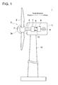
- FIG. 1 is an overall configuration diagram of a wind turbine generator according to one embodiment.
- the wind turbine generator 1 includes a rotor 5 including at least one blade 2, a hub 3 to which the at least one blade 2 is mounted in a radial fashion, and a rotation shaft 4 configured to be capable of rotating integrally with the hub 3.
- the hub 3 may be covered by a hub cover 3a.
- the rotor 5 is supported rotatably to a nacelle 11 via a main bearing.
- the nacelle 11 is mounted to an upper end portion of a tower 12 disposed on ocean or on land.
- a hydraulic pump (radial-piston type hydraulic machine) 7 is connected to the rotor 5 via the rotation shaft 4.
- a hydraulic motor 8 is connected to the hydraulic pump 7 via a high-pressure oil line 9 and a low-pressure oil line 10. Specifically, an outlet of the hydraulic pump 7 is connected to an inlet of the hydraulic motor 8 via the high pressure oil line 9, and an inlet of the hydraulic pump 7 is connected to an outlet of the hydraulic motor 8 via the low pressure oil line 10.
- the hydraulic pump 7 is driven by the rotation shaft 4 to increase the pressure of working oil, thereby producing high-pressure working oil (pressurized oil).
- the pressurized oil produced by the hydraulic pump 7 is supplied to the hydraulic motor 8 via the high-pressure oil line 9, and drives the hydraulic motor 8.
- the low-pressure working oil having performed work in the hydraulic motor 8 is returned again to the hydraulic pump 7 via the low-pressure oil line 10 disposed between the outlet of the hydraulic motor 8 and the inlet of the hydraulic pump 7.
- the generator 6 is connected to the hydraulic motor 8.
- the generator 6 is a synchronous generator connected to a utility grid and driven by the hydraulic motor 8.
- FIG. 2 is a cross-sectional view of an upper part of the radial-piston type hydraulic machine 7 according to one embodiment.
- illustrated is only the upper half section of a cross section of the radial-piston type hydraulic machine 7 along the axial direction.
- FIG. 3 is a cross-sectional view, taken in an axial direction, of the second roller bearing illustrated in FIG. 2 and its peripheral structure.
- FIG. 5 is a cross-sectional view of an upper part of the radial-piston type hydraulic machine 7 according to one embodiment.
- FIG. 6 is a partial cross-sectional view (radial cross-sectional view) of the radial-piston type hydraulic machine 7 according to one embodiment.
- the radial-piston type hydraulic machine (hereinafter, referred to merely as a hydraulic machine) 7 includes a plurality of pistons 20 arranged in the circumferential direction, a cylinder block 24 in which a plurality of cylinders 22 is formed, the first end plate 26 and the second end plate 27 disposed on opposite sides of the cylinder block 24 in the axial direction, a cam shaft 30 including a ring cam 32, the first roller bearing 60 disposed between the first end plate 26 and the cam shaft 30, and the second roller bearing disposed between the second end plate 27 and the cam shaft 30.
- a circumferential direction refers to the circumferential direction (rotational direction) of the hydraulic machine 7
- an axial direction refers to the axial direction (direction along the rotational axis O) of the hydraulic machine 7
- a radial direction refers to the radial direction of the hydraulic machine 7.
- each piston 20 includes a roller 20a contacting the cam surface of the ring cam 32, and a piston body 20b supporting the roller 20a rotatably.
- the piston body 20b is disposed so as to slide inside corresponding one of the cylinders 22 formed in the cylinder block 24.
- each piston 20 includes a ball instead of the roller 20a, and a piston body supporting the ball rotatably.
- the cylinder block 24 is disposed on the outer side of the ring cam 32 in the radial direction and arranged so as to extend in an annular shape over the entire circumference of the cam shaft 30.
- a plurality of cylinder blocks 24 may be arranged in an annular shape over the entire circumference of the cam shaft 30.
- At least one cylinder 22, as well as at least one high-pressure oil channel 40 and at least one low-pressure oil channel 50 communicating with at least one working chamber 25 in the at least one cylinder 22, are formed in each of the cylinder blocks 24.
- the high-pressure oil channel 40 includes a high-pressure oil communicating portion 46 that extends outward in the radial direction from each of the at least one working chamber 25, an axial flow channel portion 41 communicating with the high-pressure communicating portion 46 and extending along the axial direction inside the cylinder block 24, radial flow channel portions 42 communicating with the axial flow channel portion 41 and extending in the radial direction in the first end plate 26 and the cylinder block 24, and a high-pressure oil manifold portion 43 formed in a substantially annular shape inside the first end plate 26 so as to communicate with the plurality of radial flow channel portions 42.
- the low-pressure oil channel 50 includes a low-pressure oil communicating portion 51 that extends outward in the radial direction from each of the at least one working chamber 25, axial flow channel pipe portions 52 communicating with the plurality of low-pressure oil communicating portions 51 and extending along the axial direction, and a low-pressure oil manifold portion 53 to which the plurality of axial flow channel pipe portions 52 are connected.
- the low-pressure oil communicating portion 51 includes a section formed inside the cylinder block 24 and a pipe section formed outside the cylinder block 24. Further, the axial flow channel pipe portions 52 and the low-pressure oil manifold portion 53 are formed outside the cylinder block 24.
- the plurality of cylinder blocks 24 may be configured such that each cylinder block 24 is attachable to and detachable from the hydraulic pump 7, and arranged in a circumferential direction.
- a plurality of sets may be arranged in the axial direction and the circumferential direction, each set including a cylinder 22, a high-pressure oil channel 40 (specifically, a high-pressure oil communicating portion 46), and a low-pressure oil channel 50 (specifically, a low-pressure oil communicating portion 51).
- a high-pressure valve 45 is disposed in the high-pressure oil channel 40, so that the high-pressure oil channel 40 communicates with the high-pressure oil line 9 (see FIG. 1 ) when the high-pressure valve 45 opens.
- a low-pressure valve 55 is disposed in the low-pressure oil channel 50, so that the low-pressure oil channel 50 communicates with the low-pressure oil line 10 when the low-pressure valve 55 opens.
- the ring cam 32 is fixed to the outer circumference of the cam shaft 30 which rotates along with the rotation shaft 4.
- the ring cam 32 has a cam surface formed in a continuous wavy shape along the circumferential direction, and is disposed in an annular shape so as to surround the entire periphery of the cam shaft 30.
- a plurality of ring cams 32 may be disposed in the axial direction.
- the ring cam 32 is not limited to one having a cam surface of a wavy shape, but may have a cam surface of an eccentric cam which has a single cam surface with the center of the ring cam 32 being offset from the center position of the shaft. Further, as described below, the ring cam 32 may include a plurality of segments in the circumferential direction so as to be attachable to and detachable from the hydraulic machine 7.
- the first end plate 26 and the second end plate 27 are disposed on the opposite sides, in the axial direction, of the cylinder block 24, and form a stationary part of the hydraulic machine 7 with the cylinder block 24. Further, the first end plate 26 and the second end plate 27 are formed in a substantially disc shape. In one configuration example, the first end plate 26 is disposed on the front side in the axial direction, and the second end plate 27 is disposed on the rear side in the axial direction. In the present embodiment, the front side is a side close to the hub 3 in the axial direction as illustrated in FIG. 1 , and the rear side is a side remote from the hub 3 in the axial direction as illustrated in FIG. 1 .
- a seal member 36 is disposed between the first end plate 26 and the cam shaft 30, and a seal member 37 is disposed between the second end plate 27 and the cam shaft 30, so as to prevent leakage of the working oil to the outside of the hydraulic machine.
- an input shaft or an output shaft of the hydraulic machine 7 is directly connected to the cam shaft 30 of the hydraulic machine 7, and the second end plate 27 is disposed on a side opposite to the input shaft or the output shaft across the cylinder block 24 in the axial direction.
- the input shaft (rotation shaft 4) is directly connected to the cam shaft 30 of the hydraulic machine 7 by fastening members 34, and the second end plate 27 is disposed on a side opposite to the rotation shaft 4 across the cylinder block 24 with respect to the axial direction.
- the hydraulic machine 7 further includes the high-pressure oil channel 40 communicating with the working chamber 25 formed by the piston 20 and the cylinder 22, and the low-pressure oil channel 50 through which low-pressure working oil flows, the working oil having a lower pressure in the low-pressure oil channel 50 than in the high-pressure oil channel 40.
- the high-pressure oil channel 40 is disposed inside one of the first end plate 26 or the second end plate 27 and inside the cylinder block 24.
- the high-pressure oil channel 40 of the hydraulic machine 7 is disposed inside one of the end plates 26, 27 and inside the cylinder block 24. In this way, it is possible to achieve the hydraulic machine 7 having a sufficient strength to bear a pressure of the working oil in the high-pressure oil channel 40.
- one of the end plates 26, 27 and the cylinder block 24 have a fitting region at which the one of the end plates 26, 27 and the cylinder block 24 fit with each other in the axial direction.
- the high-pressure oil channel 40 includes the axial flow channel portion 41 extending along the axial direction inside the cylinder block 24, and the radial flow channel portions 42 extending along the radial direction from the axial flow channel portion 41 inside the cylinder block 24 into one of the end plates 26, 27, in the fitting region of one of the end plates 26, 27 and the cylinder block 24.
- one of the end plates 26, 27 and the cylinder block 24 are fastened by a plurality of fastening members (e.g. bolts) 80 extending in the radial direction in the fitting region.
- the radial flow channel portions 42 of the high-pressure oil channel 40 extend through the fitting region of one of the end plates 26, 27 and the cylinder block 24.
- the pressure of the working oil flowing through the radial flow channel portions 42 acts in a direction to expand a gap, in the radial direction, between one of the end plates 26, 27 and the cylinder block 24 in the fitting region of the same, which is the radial direction.
- an internal force (piston load) generated inevitably due to the characteristics of the hydraulic machine 7 is in the radial direction.
- the high-pressure oil channel 40 may be disposed so as not to pass between the other one of the first end plate 26 or the second end plate 27 and the cylinder block.
- the first end plate 26 includes the first section 26a disposed adjacently to the cylinder block 24, and the second section 26b disposed radially inside the first section 26a.
- the first section 26a includes a step (axial wall surface) on a surface facing the cylinder block 24, and is fixed to the cylinder block 24 by fastening members 80 inserted in the radial direction at this step.
- the second section 26b is fixed to the first section 26a by the fastening members 38.
- the second end plate 27 includes the first section 27a forming an axial wall surface 27e (see FIG. 3 ), the second section 27b mounted radially inside the first section 27a so as to form a radial wall surface 27d (see FIG. 3 ), and the third section 27c mounted radially inside the second section 27b.
- the first section 27a includes a step (axial wall surface) on a surface facing the cylinder block 24, and is fixed to the cylinder block 24 by the fastening members 80 inserted in the radial direction at this step.
- the second section 27b is fixed to the first section 27a by fastening members 39a from outside.
- the third section 27c is fixed to the second section 27b by fastening members 39b from outside.
- the first roller bearing 60 includes a rotary ring (inner ring) 61 fixed to the cam shaft 30 and configured to rotate with the cam shaft 30, a stationary ring (outer ring) 62 fixed to the first end plate 26, and a rolling element 63 disposed between the rotary ring 61 and the stationary ring 62.
- the first roller bearing 60 is disposed adjacently to the first end plate 26 in the axial direction.
- the second roller bearing 65 includes a rotary ring (inner ring) 66 fixed to the cam shaft 30 and configured to rotate with the cam shaft 30, a stationary ring (outer ring) 67 fixed to the second end plate 27, and a rolling element 68 disposed between the rotary ring 66 and the stationary ring 67.
- the second roller bearing 65 is disposed at a distance from the second end plate 27 so as to have a gap 35 (see FIG. 3 ) in the axial direction.
- the rotary rings 61, 66 are the inner races and the stationary rings 62, 67 are the outer races because the stationary part is disposed on the outer side and the rotary part is disposed on the inner side in the radial direction.
- the configuration is not limited to this. Specifically, in a case where the stationary part is disposed on the inner side and the rotary part is disposed on the outer side in the radial direction, the rotary ring is the outer ring and the stationary ring is the inner ring.
- the above hydraulic machine 7 includes a biasing member 70 for biasing the stationary ring 67 of the second roller bearing 65 toward the first roller bearing 60 in the axial direction.
- the biasing member 70 is disposed between an end surface of the stationary ring 67 of the second roller bearing 65 and the radial wall surface 27d of the second end plate 27 extending along the radial direction so as to face the end surface.
- a coil spring, a plate spring or the like may be used as the biasing member 70.
- the stationary ring 62 of the first roller bearing 60 is in contact with the first end plate 26 without clearance in the axial direction, while the stationary ring 67 of the second roller bearing 65 is disposed at a distance from the second end plate 27 so as to have a gap 35 in the axial direction, and the biasing member 70 is disposed between the stationary ring 67 of the second roller bearing 65 and the radial wall surface 27d of the second end plate 27.
- the stationary ring 62 of the first roller bearing 60 is forced toward the second roller bearing 65 in the axial direction by the first end plate 26, while the stationary ring 67 of the second roller bearing 65 is biased toward the first roller bearing 60 in the axial direction by the biasing member 70.
- a preload is applied to the first roller bearing 60 and the second roller bearing 65, which makes it possible to determine the position of the rotary part (cam shaft 30) in the axial direction with respect to the stationary part (the first end plate 26, the second end plate 27, and the cylinder block 24) of the hydraulic machine 7.
- the position, in the axial direction, of the stationary ring 67 of the second roller bearing 65 is not completely restricted, and movement of the stationary ring 67 of the second roller bearing 65 is allowed to a certain extent by deformation of the biasing member 70.
- the biasing member 70 As a result, even if structural deformation occurs in the hydraulic machine 7, it is possible to prevent a load applied to the rolling elements 63, 68 of the first roller bearing 60 and the second roller bearing 65 from becoming excessive.
- the hydraulic machine 7 further includes an annular resin sheet 72 disposed between a circumferential surface 67a of the stationary ring 67 of the second roller bearing 65 and an axial wall surface 27e of the second end plate 27 which extends along the axial direction so as to face the circumferential surface 67a.
- a rotary ring of a bearing is fixed to a rotary part of a rotary machine by interference fit
- a stationary ring of a bearing is fixed to a stationary part of a rotary machine by clearance fit.
- the present inventors actually assembled the hydraulic machine 7 having the above configuration and ran several trials, thereby finding out that abrasion occurs between the stationary ring 67 and the second end plate 27 in the second roller bearing 65 in which the stationary ring 67 is biased by the biasing member 70.
- the cause of the abrasion is assumed to be the relative movement of the circumferential surface of the stationary ring 67 of the second roller bearing 65 mounted by clearance fit with respect to the axial wall surface 27e of the end plate 27 in accordance with the structural deformation of the hydraulic machine 7.
- the annular resin sheet 72 is disposed between the circumferential surface 67a of the stationary ring 67 of the second roller bearing 65 and the axial wall surface 27e of the second end plate 27.
- the circumferential surface 67a of the stationary ring 67 of the second roller bearing 65 and the axial wall surface 27e of the second end plate 27 do not directly contact each other, which makes it possible to restrict wear of the stationary ring 67 of the second roller bearing 65 or the second end plate 27 due to direct slide between the same.
- the annular resin sheet 72 having lower hardness than metal may get worn from sliding on one of the above members, but the annular resin sheet 72 can be easily replaced.
- the annular resin sheet 72 has a Young's modulus smaller than that of the material (steel) of the stationary ring 67 of the second roller bearing 65 and the second end plate 27.
- annular resin sheet 72 may be fixed to one of the circumferential surface of the stationary ring 67 of the second roller bearing 65 or the axial wall surface 27e of the second end plate 27 that has a surface with larger surface roughness than the other one of the circumferential surface or the axial wall surface 27e.
- annular resin sheet 72 fixed to one of the circumferential surface 67a of the stationary ring 67 of the second roller bearing 65 or the axial wall surface 27e of the second end plate 27 that has a surface with larger surface roughness, a surface of the other one having a relatively smaller surface roughness forms a sliding surface. As a result, it is possible to restrict abrasion caused by slide even further.
- annular resin sheet 72 may be fixed to the second end plate 27.
- a stationary ring of a bearing is formed by machine processing, a stationary part such as an end plate is formed by casting.
- a stationary ring of a bearing normally has a smaller surface roughness than an end plate.
- the annular resin sheet 72 includes a region 72a that contacts the circumferential surface 67a of the stationary ring 67 of the second roller bearing 65 and a region 72b sandwiched and held between the first section 27a and the second section 27b of the second end plate 27.
- the second end plate 27 is configured to be dividable into a plurality of sections (the first section 27a and the second section 27b), and a partial region of the annular resin sheet 72 is sandwiched and held between the first section 27a and the second section 27b, which makes it possible to fix the annular resin sheet 72 to the second end plate 27.
- the circumferential surface 67a of the stationary ring 67 of the second roller bearing 65 has a smaller surface roughness than the axial wall surface 27e of the second end plate 27, with the annular resin sheet 72 fixed to the second end plate 27, the circumferential surface 67a of the stationary ring 67 of the second roller bearing 65 having a relatively smaller surface roughness becomes the sliding surface, which makes it possible to restrict abrasion caused by slide effectively.
- FIG. 4 is a cross-sectional view, in a radial direction, of the second roller bearing illustrated in FIG. 2 and its peripheral structure.
- a cross section in a radial direction refers to a cross section orthogonal to the rotational axis O.
- the annular resin sheet 72 includes a plurality of sections 72A divided in the circumferential direction.
- the annular resin sheet 72 is divided into four sections, thereby including four sections 72A.
- the number of sections 72A of the annular resin sheet 72 is not limited to this.
- annular resin sheet 72 divided into a plurality of sections 72A as described above, it is possible to facilitate the assembling work for the annular resin sheet 72.
- annular resin sheet 72 divided into a plurality of sections 72A, it is possible to adjust the diameter of the annular resin sheet 72 optionally.
- the annular resin sheet 72 includes engineering plastic or super engineering plastic.
- the annular resin sheet 72 includes at least one of polyamide (e.g. 6 nylon), polyoxymethylene (POM), or polyethylene terephthalate (PET), which are engineering plastic, or one of polyether ether ketone (PEEK), polytetrafluoroethylene (PTFE), or polyimide (PI), which are super engineering plastic.
- polyamide e.g. 6 nylon
- POM polyoxymethylene
- PET polyethylene terephthalate
- PEEK polyether ether ketone
- PTFE polytetrafluoroethylene
- PI polyimide
- the annular resin sheet 72 may include a solid lubricant containing at least one of graphite, molybdenum disulfide, polytetrafluoroethylene (PTFE), silver or lead in the material.
- the above solid lubricant may be supported on the sliding surface of the annular resin sheet 72.
- annular resin sheet 72 using a material with high abrasion resistance and sliding property such as polyamide, polyoxymethylene, polyethylene terephthalate, polyether ether ketone, polytetrafluoroethylene, or polyimide for the annular resin sheet 72 makes it possible to restrict abrasion due to slide even further.
- a material with high abrasion resistance and sliding property such as polyamide, polyoxymethylene, polyethylene terephthalate, polyether ether ketone, polytetrafluoroethylene, or polyimide
- FIG. 7 is a view as seen in the direction of arrow C of a cylinder block illustrated in FIG. 6 .
- FIG. 8A is a planar view (an enlarged view of section D of FIG. 7 ) of a tapered liner according to one embodiment.
- FIG. 8B is a cross-sectional view of the tapered liner illustrated in FIG. 8A , taken along line E-E.
- FIG. 8C is a cross-sectional view of the tapered liner illustrated in FIG. 8B , taken along line F-F.
- the hydraulic machine 7 includes a tapered liner 92, disposed between segments 24A adjacently disposed in the circumferential direction, for restricting the adjacent segments 24A with respect to each other in the axial direction.
- a shearing force accompanying operation of the hydraulic machine 7 is applied to the segments 24A of the cylinder block 24 of the hydraulic machine 7 and the fastening members 80 for fastening the segments 24A to the end plates 26, 27.
- the tapered liner 92 may include the first member 93 and the second member 94 arranged adjacently in the axial direction.
- the first member 93 has a shape such that the width, in the axial direction, decreases in a tapered fashion outwardly in the radial direction.
- the second member 94 has a shape such that the width, in the axial direction, increases in a tapered fashion outwardly in the radial direction.
- the outer circumferential surface (a section exposed to the outside of the cylinder block 24) of the tapered liner 92 may be covered by a seal member 90.
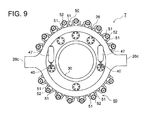
- FIG. 9 is a view as seen in the direction of arrow G of the radial-piston type hydraulic machine 7 illustrated in FIG. 2 .
- the hydraulic machine 7 further includes a high-pressure accumulator 47 supported by at least one of the cylinder block 24, the first end plate, 26 or the second end plate 27 and configured to communicate with the high-pressure oil channel 40 and restrict pulsation in the high-pressure oil channel 40.
- the high-pressure accumulator 47 is supported to the first end plate 26.
- the first end plate 26 includes a pair of torque arms 26c protruding toward opposite sides along the radial direction, and the torque arms 26c prevent rotation of the hydraulic machine 7.
- a low pressure accumulator 56 may be provided so as to communicate with the low-pressure oil channel 50.
- the low-pressure accumulator 56 is disposed outside the cylinder block 24 and configured to communicate with the axial flow channel pipe portions 52.
- the input shaft or the output shaft of the hydraulic machine 7 is directly connected to the cam shaft 30 of the hydraulic pump 7, and the second end plate 27 is disposed on the opposite side from the input shaft or the output shaft across the cylinder block 24 with respect to the axial direction.
- a method of maintaining the hydraulic machine 7 includes a maintenance step of performing maintenance on the hydraulic machine 7 while the second end plate 27 is removed from the cylinder block 24 and at least the first end plate 26 is remaining, and an attachment step of, after the maintenance step, attaching the second end plate 27 to the cylinder block 24.
- the cam shaft 30 is directly connected to the input shaft or the output shaft of the hydraulic machine 7
- the input shaft or the output shaft of the hydraulic machine 7 exists in front (a side adjacent to the first end plate 26) of the hydraulic machine 7.
- the second end plate 27 is disposed on the opposite side from the input shaft or the output shaft across the cylinder block 24 as a premise, and the second end plate 27 is removed when maintenance is performed on the hydraulic machine 7.
- the second end plate 27 is removed when maintenance is performed on the hydraulic machine 7.
- the present invention it is possible to determine the positions, with respect to the axial directions, of the rotary part (cam shaft 30) relative to the stationary part (the first end plate 26, the second end plate 27, and the cylinder block 24) of the radial-piston type hydraulic machine 7, and it is possible to restrict a load applied to the bearing upon occurrence of structural deformation.
- an expression of relative or absolute arrangement such as “in a direction”, “along a direction”, “parallel”, “orthogonal”, “centered”, “concentric” and “coaxial” shall not be construed as indicating only the arrangement in a strict literal sense, but also includes a state where the arrangement is relatively displaced by a tolerance, or by an angle or a distance whereby it is possible to achieve the same function.
- an expression of an equal state such as “same” “equal” and “uniform” shall not be construed as indicating only the state in which the feature is strictly equal, but also includes a state in which there is a tolerance or a difference that can still achieve the same function.
- an expression of a shape such as a rectangular shape or a cylindrical shape shall not be construed as only the geometrically strict shape, but also includes a shape with unevenness or chamfered corners within the range in which the same effect can be achieved.
Landscapes
- Engineering & Computer Science (AREA)
- Mechanical Engineering (AREA)
- General Engineering & Computer Science (AREA)
- Reciprocating Pumps (AREA)
- Wind Motors (AREA)
- Hydraulic Motors (AREA)
Abstract
Description
- The present disclosure relates to a radial-piston type hydraulic machine, a wind turbine generator having the same, and a method of maintaining a hydraulic machine.
- A radial-piston type hydraulic machine including a plurality of pistons arranged in a radial fashion is conventionally known.
- For instance, as a hydraulic transmission of a wind turbine generator, combination of a plurality of hydraulic machines (a hydraulic pump and a hydraulic motor) is known.
- For a wind turbine generator, a gearbox has been conventionally used as a drivetrain in many cases. Now, wind turbine generators equipped with a hydraulic transmission including the above hydraulic pump are attracting attention in terms of the weight and cost in accordance with the increase in size of the wind turbine generators.
-
Patent Documents Patent Documents -
- Patent Document 1:
WO2014/002522A - Patent Document 2:
WO2013/080399A - In a radial-piston type hydraulic machine, a thrust load may be applied to a rotation shaft. Thus, to maintain a relative positional relationship between a rotary part and a stationary part in the axial direction precisely, it is desirable to determine the position using a pair of bearings disposed between the rotary part and the stationary part.
- As a way to improve the accuracy of the determination of position by bearings, one may consider applying a preload to an outer ring or an inner ring of each of the bearings.
- However, as a result of intensive research conducted by the present inventors, it was found that structural deformation of a hydraulic machine cannot be ignored in a hydraulic machine which needs to be reduced in weight such as a hydraulic transmission for a wind turbine generator, and restricting the position of the outer ring or the inner ring of a bearing for applying a preload may result in a large load applied to the bearing. For instance, in a case where the position of the outer ring or the inner ring of each of the bearings is adjusted by managing the tightening torque of bolts and nuts, the position of the outer ring or the inner ring of the bearing is restricted, which causes an excessive load applied to a rolling element of the bearing when structural deformation occurs in the hydraulic machine.
- Especially in a case of a hydraulic machine, a large internal force (piston load) is generated at the rotary part and the stationary part due to a pressure in a hydraulic chamber. Thus, the influence of the structural deformation caused by the internal force is likely to become significant as compared to other general rotary machines.
- An object of at least some embodiments of the present invention is to provide a radial-piston hydraulic machine whereby it is possible to determine a position of a rotary part relative to a stationary part in an axial direction, and to restrict a load applied to a bearing when structural deformation occurs, as well as a wind turbine generator having the hydraulic machine and a method of maintaining a hydraulic machine.
- (1) A radial-piston type hydraulic machine according to some embodiments of the present invention includes: a plurality of pistons arranged in a circumferential direction of the hydraulic machine; a cylinder block on which a plurality of cylinders for guiding the respective pistons reciprocably along a radial direction of the hydraulic machine is formed; a first end plate and a second end plate disposed on either side of the cylinder block in an axial direction of the hydraulic machine, the first end plate and the second end plate forming a stationary part of the hydraulic machine together with the cylinder block; a cam shaft including a ring cam disposed so as to face the plurality of pistons; and a first roller bearing and a second roller bearing disposed on opposite ends of the hydraulic machine in the axial direction. The first roller bearing is disposed between the cam shaft and the first end plate. The second roller bearing is disposed between the cam shaft and the second end plate.
- Each of the first roller bearing and the second roller bearing includes: a rotary ring fixed to the cam shaft and configured to rotate with the cam shaft; a stationary ring fixed to the first end plate or the second end plate; and a rolling element disposed between the rotary ring and the stationary ring.
- The first roller bearing is disposed adjacently to the first end plate in the axial direction, and the stationary ring of the first roller bearing is in contact with the first end plate without a gap in the axial direction.
- The second roller bearing is disposed adjacently to the second end plate in the axial direction, and the stationary ring of the second roller bearing is disposed at a distance from the second end plate so as to have a gap in the axial direction.
- The hydraulic machine further includes a biasing member for biasing the stationary ring of the second roller bearing toward the first roller bearing in the axial direction. The biasing member is disposed between an end surface of the stationary ring of the second roller bearing and a radial wall surface of the second end plate, the radial wall surface extending along the radial direction so as to face the end surface.
- With the above configuration (1), the stationary ring of the first roller bearing is in contact with the first end plate without clearance in the axial direction, while the stationary ring of the second roller bearing is disposed at a distance from the second end plate so as to have a gap in the axial direction, and the biasing member is disposed between the stationary ring of the second roller bearing and the radial wall surface of the second end plate. In this way, the stationary ring of the first roller bearing is forced toward the second roller bearing in the axial direction by the first end plate, while the stationary ring of the second roller bearing is biased toward the first roller bearing in the axial direction by the biasing member. Thus, a preload is applied to the first roller bearing and the second roller bearing, which makes it possible to determine the position of the rotary part (cam shaft) in the axial direction with respect to the stationary part (the first end plate, the second end plate, and the cylinder block) of the hydraulic machine.
- Further, the position, in the axial direction, of the stationary ring of the second roller bearing is not completely restricted, and movement of the stationary ring of the second roller bearing is allowed to a certain extent by deformation of the biasing member. As a result, even if structural deformation occurs in the hydraulic machine, it is possible to prevent a load applied to the rolling elements of the first roller bearing and the second roller bearing from becoming excessive.
- (2) In some embodiments, in the above configuration (1), an annular resin sheet is disposed between a circumferential surface of the stationary ring of the second roller bearing and an axial wall surface of the second end plate, the axial wall surface extending along the axial direction so as to face the circumferential surface.
- Generally, a rotary ring of a bearing is fixed to a rotary part of a rotary machine by interference fit, while a stationary ring of a bearing is fixed to a stationary part of a rotary machine by clearance fit. If the above general concept is applied to the above hydraulic machine having the configuration (1), the rotary rings of the bearings would be fixed to the rotary part (cam shaft) of the hydraulic machine by interference fit, and the stationary rings of the bearings would be mounted to the stationary part (the first end plate and the second end plate) by clearance fit.
- The present inventors actually assembled the hydraulic machine having such configuration and ran several trials, thereby finding out that abrasion occurs between the stationary ring and the second end plate in the second roller bearing in which the stationary ring is biased by the biasing member. The cause of the abrasion is assumed to be the relative movement of the circumferential surface of the stationary ring of the second roller bearing mounted by clearance fit relative to the axial wall surface of the second end plate in accordance with the structural deformation of the hydraulic machine.
- In view of this, in the above configuration (2), the annular resin sheet is disposed between the circumferential surface of the stationary ring of the second roller bearing and the axial wall surface of the second end plate. In this way, the circumferential surface of the stationary ring of the second roller bearing and the axial wall surface of the second end plate do not directly contact each other, which makes it possible to restrict wear of the stationary ring of the second roller bearing or the second end plate due to direct slide between the same. Since the stationary ring of the second roller bearing and the second end plate are made of metal (steel), the annular resin sheet having lower hardness than metal may get worn from sliding on one of the above members, but the annular resin sheet can be easily replaced.
- Further, the annular resin sheet has a Young's modulus smaller than that of the material (steel) of the stationary ring of the second roller bearing and the second end plate. Thus, it is possible to reduce a local surface pressure applied between the stationary ring of the second roller bearing and the second end plate as compared to a case where metal materials directly contact each other. As a result, it is possible to restrict abrasion due to slide effectively.
- (3) In some embodiments, in the above configuration (2), the annular resin sheet is fixed to one of the circumferential surface of the stationary ring of the second roller bearing or the axial wall surface of the second end plate which has a surface with a larger surface roughness.
- Normally, if conditions such as a surface pressure and a slipping velocity are the same, the smaller the surface roughness of a sliding surface is the amount of abrasion is small.
- In this regard, in the above configuration (3), with the annular resin sheet fixed to one of the circumferential surface of the stationary ring of the second roller bearing or the axial wall surface of the second end plate that has a surface with larger surface roughness, a surface of the another one having a relatively smaller surface roughness forms a sliding surface. As a result, it is possible to restrict abrasion caused by slide even further.
- (4) In some embodiments, in the above configuration (2) or (3), the annular resin sheet is fixed to the second end plate.
- Normally, while a stationary ring of a bearing is formed by machine processing, a stationary part such as an end plate is formed by casting. Thus, a stationary ring of a bearing normally has a smaller surface roughness than an end plate.
- In this regard, in the above configuration (4), the annular resin sheet is fixed to the second end plate so that the circumferential surface of the second roller bearing having a relatively smaller surface roughness becomes the sliding surface. As a result, it is possible to restrict abrasion due to slide effectively.
- (5) In some embodiments, in any one of the configurations (2) to (4), the second end plate includes: a first section which forms the axial wall surface; and a second section which forms the radial wall surface, the second section being attached to the first section.
- The annular resin sheet includes: a region which is in contact with the circumferential surface of the stationary ring of the second roller bearing; and a region sandwiched and held between the first section and the second section of the second end plate.
- With the above configuration (5), the second end plate is dividable into a plurality of sections (the first section and the second section), and a partial region of the annular resin sheet is sandwiched and held between the first section and the second section, which makes it possible to fix the annular resin sheet to the second end plate.
- Further, in a case where the circumferential surface of the stationary ring of the second roller bearing has a smaller surface roughness than the axial wall surface of the second end plate, with the annular resin sheet being fixed to the second end plate as in the above configuration (5), the circumferential surface of the second roller bearing having a relatively smaller surface roughness becomes the sliding surface, which makes it possible to restrict abrasion caused by slide effectively.
- (6) In some embodiments, in any one of the above configurations (2) to (5), the annular resin sheet includes a plurality of sections divided in the circumferential direction.
- In the above configuration (6), with the annular resin sheet divided into a plurality of sections, it is possible to facilitate the assembling work for the annular resin sheet.
- Further, with the annular resin sheet divided into a plurality of sections, it is possible to adjust the diameter of the annular resin sheet optionally. Thus, it is possible to apply the annular resin sheet to a plurality of types of hydraulic machines having a second roller bearing of different size by varying the number of sections of the annular resin sheet, which makes it possible to restrict an increase in cost due to additional provision of the annular resin sheet.
- In some embodiments, in any one of the above configurations (2) to (6), the annular resin sheet includes at least one of polyamide, polyacetal, polyethylene terephthalate, polyether ether ketone, polytetrafluoroethylene, or polyimide.
- Further, in any one of the above configurations (2) to (6), the annular resin sheet may include a solid lubricant containing at least one of graphite, molybdenum disulfide, polytetrafluoroethylene (PTFE), silver or lead in the material. Alternatively, the above solid lubricant may be supported on the sliding surface of the annular resin sheet.
- With the above configuration (7), using a material with high abrasion resistance and sliding property such as polyamide, polyoxymethylene, polyethylene terephthalate, polyether ether ketone, polytetrafluoroethylene, or polyimide for the annular resin sheet makes it possible to restrict abrasion due to slide even further.
- (8) In some embodiments, in any one of the configurations (1) to (7), the radial-piston type hydraulic machine further includes a high-pressure oil channel communicating with working chambers formed by the pistons and the cylinders, and a low-pressure oil channel through which working oil flows. The working oil has a lower pressure in the low-pressure oil channel than in the high-pressure oil channel. The high-pressure oil channel is disposed inside one of the first end plate or the second end plate and inside the cylinder block.
- In the above configuration (8), the high-pressure oil channel of the hydraulic machine is disposed inside one of the end plates and inside the cylinder block. In this way, it is possible to achieve the hydraulic machine having a sufficient strength with respect to a pressure of the working oil in the high-pressure oil channel.
- (9) In some embodiments, in the above configuration (8), the one of the end plates and the cylinder block have a fitting region at which the one of the end plates and the cylinder block fit with each other in the axial direction. The high-pressure oil channel includes: an axial flow channel portion extending along the axial direction inside the cylinder block; and a radial flow channel portion extending along the radial direction into the one of the end plates from the axial flow channel portion in the cylinder block in the fitting region of the one of the end plates and the cylinder block. The one of the end plates and the cylinder block are fastened by a plurality of fastening members extending in the radial direction in the fitting region.
- In the above configuration (9), the radial flow channel portion of the high-pressure oil channel extends through the fitting region of one of the end plates and the cylinder block. Thus, the pressure of the working oil flowing through the radial flow channel portion acts in a direction to expand a gap, in the radial direction, between one of the end plates and the cylinder block in the fitting region of the same, which is the radial direction. Similarly, an internal force (piston load) generated inevitably due to the characteristics of the hydraulic machine also acts in the radial direction. As described above, since the force caused by the hydraulic pressure acting between one of the end plates and the cylinder block and the internal force (piston load) of the hydraulic machine are in the same direction (since both forces act in the radial direction), it is possible to simplify the fastening structure between the end plates and the cylinder block. In other words, it is basically possible to bear the above two kinds of forces by fastening members oriented in one direction by fastening the end plates and the cylinder block using the fastening members extending in the radial direction in the fitting region.
- (10) In some embodiments, in the above configuration (8) or (9), the high-pressure oil channel is disposed so as not to extend across from the cylinder block to other one of the first end plate or the second end plate.
- In this way, during maintenance of the hydraulic machine, it is possible to attach or remove the end plate not including the high-pressure oil channel (the other one of the first end plate or the second end plate) easily.
- (11) In some embodiments, in any one of the above configurations (8) to (10), the radial-piston type hydraulic machine further includes a high-pressure accumulator supported by one of the cylinder block, the first end plate, or the second end plate, and configured to communicate with the high-pressure oil channel and to restrict pulsation in the high-pressure oil channel.
- With the above configuration (11), it is possible to restrict pulsation in the high-pressure oil channel with the high pressure accumulator and to reduce vibration of the hydraulic machine due to the pulsation. Thus, it is possible to secure the strength of the hydraulic machine easily.
- (12) In some embodiments, in any one of the above configurations (1) to (11), the cylinder block includes a plurality of segments divided in the circumferential direction. The radial-piston type hydraulic machine further includes a tapered liner disposed between two of the plurality of segments disposed adjacently in the circumferential direction for securing the adjacent two segments with respect to each other in the axial direction.
- A shearing force accompanying operation of the hydraulic machine is applied to the segments of the cylinder block of the hydraulic machine and the fastening members for fastening the segments to the end plates.
- In view of this, with the above configuration (12), the axial positions of adjacent segments of the cylinder block with respect to each other are restricted by the tapered liners, which makes it possible to secure a sufficient strength against the above shearing force accompanying operation of the hydraulic machine.
- In some embodiments, in the above configurations (1) to (12), the hydraulic machine includes an input shaft or an output shaft directly connected to the cam shaft of the hydraulic machine, and the second end plate is disposed on an opposite side of the cylinder block from the input shaft or the output shaft with respect to the axial direction.
- (13) A wind turbine generator according to at least some embodiments of the present invention includes: a rotor configured to rotate upon receiving wind; a hydraulic pump configured to be driven by the rotor to produce pressurized oil; and a hydraulic motor driven by the pressurized oil. The hydraulic pump is the radial-piston type hydraulic machine according to any one of the above (1) to (12).
- In the above configuration (13), the hydraulic pump has one of the above configurations (1) to (12). Thus, as described above, a preload is applied to the first roller bearing and the second roller bearing, which makes it possible to determine the position of the rotary part (cam shaft) in the axial direction with respect to the stationary part (the first end plate, the second end plate, and the cylinder block) of the hydraulic machine. Further, even if structural deformation occurs in the hydraulic machine, it is possible to prevent a load applied to the rolling elements of the first roller bearing and the second roller bearing from becoming excessive.
- (14) In some embodiments, in the above configuration (13), the cam shaft of the hydraulic pump is connected to the rotor directly, and the second end plate is disposed on an opposite side of the cylinder block from the rotor with respect to the axial direction.
- In a case where the cam shaft of the hydraulic pump is directly connected to the rotor of the wind turbine generator, the rotor of the wind turbine generator exists in front (a side adjacent to the first end plate) of the hydraulic pump. Thus, it is easier to secure a space for maintenance at the rear side (a side adjacent to the second end plate) of the hydraulic pump.
- In this regard, in the above configuration (14), the second end plate is disposed on the opposite side from the rotor across the cylinder block. In this way, it is possible to replace expendable supplies (biasing members, annular resin sheet, etc.) on the side of the second end plate easily utilizing the space for maintenance at the rear of the hydraulic pump.
- (15) A method of maintaining a radial-piston type hydraulic machine according to at least some embodiments of the present invention is for the radial-piston type hydraulic machine according to any one of the above (1) to (12). The hydraulic machine includes an input shaft or an output shaft directly connected to the cam shaft of the hydraulic machine, and the second end plate is disposed on an opposite side of the cylinder block from the input shaft or the output shaft with respect to the axial direction. The method includes: a maintenance step of maintaining the hydraulic machine while the second end plate is removed from the cylinder block and at least the first end plate is remaining; and an attachment step of attaching the second end plate to the cylinder block after the maintenance step.
- In a case where the cam shaft is directly connected to the input shaft or the output shaft of the hydraulic machine, the input shaft or the output shaft of the hydraulic machine exists in front (a side adjacent to the first end plate) of the hydraulic machine. Thus, it is easier to secure a space for maintenance at the rear side (a side adjacent to the second end plate) of the hydraulic machine.
- In this regard, according to the above method (15), the second end plate is disposed on the opposite side from the input shaft or the output shaft across the cylinder block as a premise, and the second end plate is removed when maintenance is performed on the hydraulic machine. Thus, it is possible to utilize the space for maintenance at the rear side of the hydraulic machine to perform maintenance works for the hydraulic machine efficiently.
- According to at least one embodiment of the present invention, it is possible to determine a position of a rotary part relative to a stationary part in an axial direction, in a radial-piston type hydraulic machine, and to restrict a load applied to a bearing when structural deformation occurs.
-
-
FIG. 1 is an overall configuration diagram of a wind turbine generator according to one embodiment. -
FIG. 2 is a cross-sectional view of an upper part of a radial-piston type hydraulic machine according to one embodiment. -
FIG. 3 is a cross-sectional view, taken in an axial direction, of the second roller bearing illustrated inFIG. 2 and its peripheral structure. -
FIG. 4 is a cross-sectional view, taken in a radial direction, of the second roller bearing illustrated inFIG. 2 and its peripheral structure. -
FIG. 5 is a cross-sectional view of an upper part of a radial-piston type hydraulic machine according to one embodiment. -
FIG. 6 is a partial cross-sectional view (radial cross-sectional view) of a radial-piston type hydraulic machine according to one embodiment. -
FIG. 7 is a view as seen in the direction of arrow C of the cylinder block illustrated inFIG. 6 . -
FIG. 8A is a planar view (an enlarged view of section D ofFIG. 7 ) of a tapered liner according to one embodiment.FIG. 8B is a cross-sectional view of the tapered liner illustrated inFIG. 8A , taken along line E-E.FIG. 8C is a cross-sectional view of the tapered liner illustrated inFIG. 8B , taken along line F-F. -
FIG. 9 is a view as seen in the direction of arrow G of the radial-piston type hydraulic machine according toFIG. 2 . - Embodiments of the present invention will now be described in detail with reference to the accompanying drawings. It is intended, however, that unless particularly specified, dimensions, materials, shapes, relative positions and the like of components described in the embodiments shall be interpreted as illustrative only and not limitative of the scope of the present invention.
- In the present embodiment, a hydraulic pump of a wind turbine generator will be described as an example of a radial-piston type hydraulic machine. However, application of the radial-piston type hydraulic machine according to the present embodiment is not limited to a hydraulic pump for a wind turbine generator, and the radial-piston type hydraulic machine according to the present invention may be applied to a hydraulic motor of a wind turbine generator, or apparatuses other than a wind turbine generator such as an industrial vehicle, an industrial machine, and a device for a ship.
- Firstly, with reference to
FIG. 1 , the overall configuration of awind turbine generator 1 according to one embodiment will be described.FIG. 1 is an overall configuration diagram of a wind turbine generator according to one embodiment. - As illustrated in
FIG. 1 , thewind turbine generator 1 according to one embodiment includes arotor 5 including at least oneblade 2, ahub 3 to which the at least oneblade 2 is mounted in a radial fashion, and arotation shaft 4 configured to be capable of rotating integrally with thehub 3. Thehub 3 may be covered by ahub cover 3a. Therotor 5 is supported rotatably to anacelle 11 via a main bearing. Thenacelle 11 is mounted to an upper end portion of atower 12 disposed on ocean or on land. - A hydraulic pump (radial-piston type hydraulic machine) 7 is connected to the
rotor 5 via therotation shaft 4. Ahydraulic motor 8 is connected to thehydraulic pump 7 via a high-pressure oil line 9 and a low-pressure oil line 10. Specifically, an outlet of thehydraulic pump 7 is connected to an inlet of thehydraulic motor 8 via the high pressure oil line 9, and an inlet of thehydraulic pump 7 is connected to an outlet of thehydraulic motor 8 via the lowpressure oil line 10. Thehydraulic pump 7 is driven by therotation shaft 4 to increase the pressure of working oil, thereby producing high-pressure working oil (pressurized oil). The pressurized oil produced by thehydraulic pump 7 is supplied to thehydraulic motor 8 via the high-pressure oil line 9, and drives thehydraulic motor 8. The low-pressure working oil having performed work in thehydraulic motor 8 is returned again to thehydraulic pump 7 via the low-pressure oil line 10 disposed between the outlet of thehydraulic motor 8 and the inlet of thehydraulic pump 7. - The
generator 6 is connected to thehydraulic motor 8. For instance, thegenerator 6 is a synchronous generator connected to a utility grid and driven by thehydraulic motor 8. - Next, with reference to
FIGs. 2 ,3 ,5 and6 , a radial-piston type hydraulic machine (for example, a hydraulic pump) 7 according to one embodiment will be described.FIG. 2 is a cross-sectional view of an upper part of the radial-piston typehydraulic machine 7 according to one embodiment. InFIG. 2 , illustrated is only the upper half section of a cross section of the radial-piston typehydraulic machine 7 along the axial direction.FIG. 3 is a cross-sectional view, taken in an axial direction, of the second roller bearing illustrated inFIG. 2 and its peripheral structure.FIG. 5 is a cross-sectional view of an upper part of the radial-piston typehydraulic machine 7 according to one embodiment.FIG. 6 is a partial cross-sectional view (radial cross-sectional view) of the radial-piston typehydraulic machine 7 according to one embodiment. - As illustrated in
FIGs. 2 ,5 and6 , the radial-piston type hydraulic machine (hereinafter, referred to merely as a hydraulic machine) 7 includes a plurality ofpistons 20 arranged in the circumferential direction, acylinder block 24 in which a plurality ofcylinders 22 is formed, thefirst end plate 26 and thesecond end plate 27 disposed on opposite sides of thecylinder block 24 in the axial direction, acam shaft 30 including aring cam 32, thefirst roller bearing 60 disposed between thefirst end plate 26 and thecam shaft 30, and the second roller bearing disposed between thesecond end plate 27 and thecam shaft 30. In the present embodiment, a circumferential direction refers to the circumferential direction (rotational direction) of thehydraulic machine 7, an axial direction refers to the axial direction (direction along the rotational axis O) of thehydraulic machine 7, and a radial direction refers to the radial direction of thehydraulic machine 7. - A plurality of
pistons 20 is arranged in a radial fashion on the outer side, in the radial direction, of thering cam 32. In one configuration example, eachpiston 20 includes aroller 20a contacting the cam surface of thering cam 32, and apiston body 20b supporting theroller 20a rotatably. Thepiston body 20b is disposed so as to slide inside corresponding one of thecylinders 22 formed in thecylinder block 24. In another configuration example, eachpiston 20 includes a ball instead of theroller 20a, and a piston body supporting the ball rotatably. - The
cylinder block 24 is disposed on the outer side of thering cam 32 in the radial direction and arranged so as to extend in an annular shape over the entire circumference of thecam shaft 30. In one configuration example, a plurality ofcylinder blocks 24 may be arranged in an annular shape over the entire circumference of thecam shaft 30. At least onecylinder 22, as well as at least one high-pressure oil channel 40 and at least one low-pressure oil channel 50 communicating with at least one workingchamber 25 in the at least onecylinder 22, are formed in each of the cylinder blocks 24. For instance, the high-pressure oil channel 40 includes a high-pressureoil communicating portion 46 that extends outward in the radial direction from each of the at least one workingchamber 25, an axialflow channel portion 41 communicating with the high-pressure communicating portion 46 and extending along the axial direction inside thecylinder block 24, radialflow channel portions 42 communicating with the axialflow channel portion 41 and extending in the radial direction in thefirst end plate 26 and thecylinder block 24, and a high-pressureoil manifold portion 43 formed in a substantially annular shape inside thefirst end plate 26 so as to communicate with the plurality of radialflow channel portions 42. Further, the low-pressure oil channel 50 includes a low-pressureoil communicating portion 51 that extends outward in the radial direction from each of the at least one workingchamber 25, axial flowchannel pipe portions 52 communicating with the plurality of low-pressureoil communicating portions 51 and extending along the axial direction, and a low-pressureoil manifold portion 53 to which the plurality of axial flowchannel pipe portions 52 are connected. The low-pressureoil communicating portion 51 includes a section formed inside thecylinder block 24 and a pipe section formed outside thecylinder block 24. Further, the axial flowchannel pipe portions 52 and the low-pressureoil manifold portion 53 are formed outside thecylinder block 24. - The plurality of
cylinder blocks 24 may be configured such that eachcylinder block 24 is attachable to and detachable from thehydraulic pump 7, and arranged in a circumferential direction. In this case, for each one of the cylinder blocks 24, a plurality of sets may be arranged in the axial direction and the circumferential direction, each set including acylinder 22, a high-pressure oil channel 40 (specifically, a high-pressure oil communicating portion 46), and a low-pressure oil channel 50 (specifically, a low-pressure oil communicating portion 51). A high-pressure valve 45 is disposed in the high-pressure oil channel 40, so that the high-pressure oil channel 40 communicates with the high-pressure oil line 9 (seeFIG. 1 ) when the high-pressure valve 45 opens. A low-pressure valve 55 is disposed in the low-pressure oil channel 50, so that the low-pressure oil channel 50 communicates with the low-pressure oil line 10 when the low-pressure valve 55 opens. - The
ring cam 32 is fixed to the outer circumference of thecam shaft 30 which rotates along with therotation shaft 4. Thering cam 32 has a cam surface formed in a continuous wavy shape along the circumferential direction, and is disposed in an annular shape so as to surround the entire periphery of thecam shaft 30. A plurality ofring cams 32 may be disposed in the axial direction. Thering cam 32 is not limited to one having a cam surface of a wavy shape, but may have a cam surface of an eccentric cam which has a single cam surface with the center of thering cam 32 being offset from the center position of the shaft. Further, as described below, thering cam 32 may include a plurality of segments in the circumferential direction so as to be attachable to and detachable from thehydraulic machine 7. - The
first end plate 26 and thesecond end plate 27 are disposed on the opposite sides, in the axial direction, of thecylinder block 24, and form a stationary part of thehydraulic machine 7 with thecylinder block 24. Further, thefirst end plate 26 and thesecond end plate 27 are formed in a substantially disc shape. In one configuration example, thefirst end plate 26 is disposed on the front side in the axial direction, and thesecond end plate 27 is disposed on the rear side in the axial direction. In the present embodiment, the front side is a side close to thehub 3 in the axial direction as illustrated inFIG. 1 , and the rear side is a side remote from thehub 3 in the axial direction as illustrated inFIG. 1 . - A
seal member 36 is disposed between thefirst end plate 26 and thecam shaft 30, and aseal member 37 is disposed between thesecond end plate 27 and thecam shaft 30, so as to prevent leakage of the working oil to the outside of the hydraulic machine. - Further, an input shaft or an output shaft of the
hydraulic machine 7 is directly connected to thecam shaft 30 of thehydraulic machine 7, and thesecond end plate 27 is disposed on a side opposite to the input shaft or the output shaft across thecylinder block 24 in the axial direction. In the example illustrated inFIG. 1 , the input shaft (rotation shaft 4) is directly connected to thecam shaft 30 of thehydraulic machine 7 byfastening members 34, and thesecond end plate 27 is disposed on a side opposite to therotation shaft 4 across thecylinder block 24 with respect to the axial direction. - In one embodiment, the
hydraulic machine 7 further includes the high-pressure oil channel 40 communicating with the workingchamber 25 formed by thepiston 20 and thecylinder 22, and the low-pressure oil channel 50 through which low-pressure working oil flows, the working oil having a lower pressure in the low-pressure oil channel 50 than in the high-pressure oil channel 40. - The high-
pressure oil channel 40 is disposed inside one of thefirst end plate 26 or thesecond end plate 27 and inside thecylinder block 24. - In the above configuration, the high-
pressure oil channel 40 of thehydraulic machine 7 is disposed inside one of theend plates cylinder block 24. In this way, it is possible to achieve thehydraulic machine 7 having a sufficient strength to bear a pressure of the working oil in the high-pressure oil channel 40. - Specifically, one of the
end plates cylinder block 24 have a fitting region at which the one of theend plates cylinder block 24 fit with each other in the axial direction. Further, the high-pressure oil channel 40 includes the axialflow channel portion 41 extending along the axial direction inside thecylinder block 24, and the radialflow channel portions 42 extending along the radial direction from the axialflow channel portion 41 inside thecylinder block 24 into one of theend plates end plates cylinder block 24. Further, one of theend plates cylinder block 24 are fastened by a plurality of fastening members (e.g. bolts) 80 extending in the radial direction in the fitting region. - In the above configuration, the radial
flow channel portions 42 of the high-pressure oil channel 40 extend through the fitting region of one of theend plates cylinder block 24. Thus, the pressure of the working oil flowing through the radialflow channel portions 42 acts in a direction to expand a gap, in the radial direction, between one of theend plates cylinder block 24 in the fitting region of the same, which is the radial direction. Similarly, an internal force (piston load) generated inevitably due to the characteristics of thehydraulic machine 7 is in the radial direction. As described above, since the force caused by the hydraulic pressure acting between one of theend plates cylinder block 24 and the internal force (piston load) of thehydraulic machine 7 are in the same direction (because both forces act in the radial direction), it is possible to simplify the fastening structure between theend plates cylinder block 24. In other words, it is basically possible to bear the above two kinds of forces with fastening members oriented in one direction by fastening theend plates cylinder block 24 with fastening members extending in the radial direction in the fitting region. - In this case, the high-
pressure oil channel 40 may be disposed so as not to pass between the other one of thefirst end plate 26 or thesecond end plate 27 and the cylinder block. - In this way, during maintenance of the
hydraulic machine 7, it is possible to attach or remove the end plate not including the high-pressure oil channel 40 (the other one of thefirst end plate 26 or the second end plate 27) easily. - In one configuration, the
first end plate 26 includes thefirst section 26a disposed adjacently to thecylinder block 24, and thesecond section 26b disposed radially inside thefirst section 26a. As illustrated inFIG. 5 , thefirst section 26a includes a step (axial wall surface) on a surface facing thecylinder block 24, and is fixed to thecylinder block 24 byfastening members 80 inserted in the radial direction at this step. Thesecond section 26b is fixed to thefirst section 26a by thefastening members 38. With this configuration, it is possible to access thefirst roller bearing 60 by removing only thesecond section 26b while thefirst section 26a is still fixed to thecylinder block 24, which makes it possible to perform maintenance on thefirst roller bearing 60 easily. - Further, the
second end plate 27 includes thefirst section 27a forming anaxial wall surface 27e (seeFIG. 3 ), thesecond section 27b mounted radially inside thefirst section 27a so as to form aradial wall surface 27d (seeFIG. 3 ), and thethird section 27c mounted radially inside thesecond section 27b. As illustrated inFIG. 5 , thefirst section 27a includes a step (axial wall surface) on a surface facing thecylinder block 24, and is fixed to thecylinder block 24 by thefastening members 80 inserted in the radial direction at this step. Thesecond section 27b is fixed to thefirst section 27a byfastening members 39a from outside. Thethird section 27c is fixed to thesecond section 27b by fasteningmembers 39b from outside. With this configuration, it is possible to access thesecond roller bearing 65 or a biasingmember 70 described below by removing only thesecond section 27b, or thesecond section 27b and thethird section 27c, while thefirst section 27a is still fixed to thecylinder block 24. Thus, it is possible to perform maintenance on thesecond roller bearing 65 or the biasingmember 70 easily. - As illustrated in
FIGs. 2 and5 , thefirst roller bearing 60 includes a rotary ring (inner ring) 61 fixed to thecam shaft 30 and configured to rotate with thecam shaft 30, a stationary ring (outer ring) 62 fixed to thefirst end plate 26, and a rollingelement 63 disposed between therotary ring 61 and thestationary ring 62. Thefirst roller bearing 60 is disposed adjacently to thefirst end plate 26 in the axial direction. - As illustrated in
FIGs. 2 ,3 and5 , thesecond roller bearing 65 includes a rotary ring (inner ring) 66 fixed to thecam shaft 30 and configured to rotate with thecam shaft 30, a stationary ring (outer ring) 67 fixed to thesecond end plate 27, and a rollingelement 68 disposed between therotary ring 66 and thestationary ring 67. Thesecond roller bearing 65 is disposed at a distance from thesecond end plate 27 so as to have a gap 35 (seeFIG. 3 ) in the axial direction. - In the illustrated example, the rotary rings 61, 66 are the inner races and the
stationary rings - Further, the above
hydraulic machine 7 includes a biasingmember 70 for biasing thestationary ring 67 of thesecond roller bearing 65 toward thefirst roller bearing 60 in the axial direction. The biasingmember 70 is disposed between an end surface of thestationary ring 67 of thesecond roller bearing 65 and theradial wall surface 27d of thesecond end plate 27 extending along the radial direction so as to face the end surface. As the biasingmember 70, a coil spring, a plate spring or the like may be used. - With the above configuration, the
stationary ring 62 of thefirst roller bearing 60 is in contact with thefirst end plate 26 without clearance in the axial direction, while thestationary ring 67 of thesecond roller bearing 65 is disposed at a distance from thesecond end plate 27 so as to have a gap 35 in the axial direction, and the biasingmember 70 is disposed between thestationary ring 67 of thesecond roller bearing 65 and theradial wall surface 27d of thesecond end plate 27. In this way, thestationary ring 62 of thefirst roller bearing 60 is forced toward thesecond roller bearing 65 in the axial direction by thefirst end plate 26, while thestationary ring 67 of thesecond roller bearing 65 is biased toward thefirst roller bearing 60 in the axial direction by the biasingmember 70. Thus, a preload is applied to thefirst roller bearing 60 and thesecond roller bearing 65, which makes it possible to determine the position of the rotary part (cam shaft 30) in the axial direction with respect to the stationary part (thefirst end plate 26, thesecond end plate 27, and the cylinder block 24) of thehydraulic machine 7. - Further, the position, in the axial direction, of the
stationary ring 67 of thesecond roller bearing 65 is not completely restricted, and movement of thestationary ring 67 of thesecond roller bearing 65 is allowed to a certain extent by deformation of the biasingmember 70. As a result, even if structural deformation occurs in thehydraulic machine 7, it is possible to prevent a load applied to the rollingelements first roller bearing 60 and thesecond roller bearing 65 from becoming excessive. - As illustrated in
FIG. 3 , in one embodiment, thehydraulic machine 7 further includes anannular resin sheet 72 disposed between acircumferential surface 67a of thestationary ring 67 of thesecond roller bearing 65 and anaxial wall surface 27e of thesecond end plate 27 which extends along the axial direction so as to face thecircumferential surface 67a. - Generally, a rotary ring of a bearing is fixed to a rotary part of a rotary machine by interference fit, while a stationary ring of a bearing is fixed to a stationary part of a rotary machine by clearance fit. If the above general concept is applied to the above
hydraulic machine 7, the rotary rings 61, 66 of thebearings hydraulic machine 7 by interference fit, and thestationary rings bearings first end plate 26 and the second end plate 27) of thehydraulic machine 7 by clearance fit. - The present inventors actually assembled the
hydraulic machine 7 having the above configuration and ran several trials, thereby finding out that abrasion occurs between thestationary ring 67 and thesecond end plate 27 in thesecond roller bearing 65 in which thestationary ring 67 is biased by the biasingmember 70. The cause of the abrasion is assumed to be the relative movement of the circumferential surface of thestationary ring 67 of thesecond roller bearing 65 mounted by clearance fit with respect to theaxial wall surface 27e of theend plate 27 in accordance with the structural deformation of thehydraulic machine 7. - In view of this, in the above configuration, the
annular resin sheet 72 is disposed between thecircumferential surface 67a of thestationary ring 67 of thesecond roller bearing 65 and theaxial wall surface 27e of thesecond end plate 27. In this way, thecircumferential surface 67a of thestationary ring 67 of thesecond roller bearing 65 and theaxial wall surface 27e of thesecond end plate 27 do not directly contact each other, which makes it possible to restrict wear of thestationary ring 67 of thesecond roller bearing 65 or thesecond end plate 27 due to direct slide between the same. Since thestationary ring 67 of thesecond roller bearing 65 and thesecond end plate 27 are made of metal (steel), theannular resin sheet 72 having lower hardness than metal may get worn from sliding on one of the above members, but theannular resin sheet 72 can be easily replaced. - Further, the
annular resin sheet 72 has a Young's modulus smaller than that of the material (steel) of thestationary ring 67 of thesecond roller bearing 65 and thesecond end plate 27. Thus, it is possible to reduce a local surface pressure applied between thestationary ring 67 of thesecond roller bearing 65 and thesecond end plate 27 as compared to a case where metal members directly contact each other. As a result, it is possible to restrict abrasion due to slide effectively. - Further, the
annular resin sheet 72 may be fixed to one of the circumferential surface of thestationary ring 67 of thesecond roller bearing 65 or theaxial wall surface 27e of thesecond end plate 27 that has a surface with larger surface roughness than the other one of the circumferential surface or theaxial wall surface 27e. - Normally, if conditions such as a surface pressure and a slipping velocity are the same, the smaller the surface roughness of a sliding surface is the amount of abrasion is small.
- In this regard, with the
annular resin sheet 72 fixed to one of thecircumferential surface 67a of thestationary ring 67 of thesecond roller bearing 65 or theaxial wall surface 27e of thesecond end plate 27 that has a surface with larger surface roughness, a surface of the other one having a relatively smaller surface roughness forms a sliding surface. As a result, it is possible to restrict abrasion caused by slide even further. - Moreover, the
annular resin sheet 72 may be fixed to thesecond end plate 27. - Normally, while a stationary ring of a bearing is formed by machine processing, a stationary part such as an end plate is formed by casting. Thus, a stationary ring of a bearing normally has a smaller surface roughness than an end plate.
- In this regard, with the
annular resin sheet 72 fixed to thesecond end plate 27 so that thecircumferential surface 67a of thestationary ring 67 of thesecond roller bearing 65 having a relatively smaller surface roughness becomes the sliding surface, it is possible to restrict abrasion due to slide effectively. - In one embodiment, in a case where the second end plate includes the
first section 27a forming theaxial wall surface 27e and thesecond section 27b which is mounted to the first section and which forms theradial wall surface 27d, theannular resin sheet 72 includes a region 72a that contacts thecircumferential surface 67a of thestationary ring 67 of thesecond roller bearing 65 and a region 72b sandwiched and held between thefirst section 27a and thesecond section 27b of thesecond end plate 27. - With the above configuration, the
second end plate 27 is configured to be dividable into a plurality of sections (thefirst section 27a and thesecond section 27b), and a partial region of theannular resin sheet 72 is sandwiched and held between thefirst section 27a and thesecond section 27b, which makes it possible to fix theannular resin sheet 72 to thesecond end plate 27. - Further, in a case where the
circumferential surface 67a of thestationary ring 67 of thesecond roller bearing 65 has a smaller surface roughness than theaxial wall surface 27e of thesecond end plate 27, with theannular resin sheet 72 fixed to thesecond end plate 27, thecircumferential surface 67a of thestationary ring 67 of thesecond roller bearing 65 having a relatively smaller surface roughness becomes the sliding surface, which makes it possible to restrict abrasion caused by slide effectively. -
FIG. 4 is a cross-sectional view, in a radial direction, of the second roller bearing illustrated inFIG. 2 and its peripheral structure. A cross section in a radial direction refers to a cross section orthogonal to the rotational axis O. - In one embodiment, the
annular resin sheet 72 includes a plurality ofsections 72A divided in the circumferential direction. In the illustrated example, theannular resin sheet 72 is divided into four sections, thereby including foursections 72A. However, the number ofsections 72A of theannular resin sheet 72 is not limited to this. - With the
annular resin sheet 72 divided into a plurality ofsections 72A as described above, it is possible to facilitate the assembling work for theannular resin sheet 72. - Further, with the
annular resin sheet 72 divided into a plurality ofsections 72A, it is possible to adjust the diameter of theannular resin sheet 72 optionally. Thus, it is possible to apply theannular resin sheet 72 to a plurality of types of thehydraulic machine 7 having thesecond roller bearing 65 of different size by varying the number of sections of theannular resin sheet 72, which makes it possible to restrict an increase in cost due to additional provision of theannular resin sheet 72. - Further, in one embodiment, the
annular resin sheet 72 includes engineering plastic or super engineering plastic. Specifically, theannular resin sheet 72 includes at least one of polyamide (e.g. 6 nylon), polyoxymethylene (POM), or polyethylene terephthalate (PET), which are engineering plastic, or one of polyether ether ketone (PEEK), polytetrafluoroethylene (PTFE), or polyimide (PI), which are super engineering plastic. - Here, the
annular resin sheet 72 may include a solid lubricant containing at least one of graphite, molybdenum disulfide, polytetrafluoroethylene (PTFE), silver or lead in the material. Alternatively, the above solid lubricant may be supported on the sliding surface of theannular resin sheet 72. - As described above, using a material with high abrasion resistance and sliding property such as polyamide, polyoxymethylene, polyethylene terephthalate, polyether ether ketone, polytetrafluoroethylene, or polyimide for the
annular resin sheet 72 makes it possible to restrict abrasion due to slide even further. -
FIG. 7 is a view as seen in the direction of arrow C of a cylinder block illustrated inFIG. 6 .FIG. 8A is a planar view (an enlarged view of section D ofFIG. 7 ) of a tapered liner according to one embodiment.FIG. 8B is a cross-sectional view of the tapered liner illustrated inFIG. 8A , taken along line E-E.FIG. 8C is a cross-sectional view of the tapered liner illustrated inFIG. 8B , taken along line F-F. - As illustrated in
FIGs. 7 ,8A to 8C , in a case of one embodiment where thecylinder block 24 includes a plurality ofsegments 24A divided in the circumferential direction, thehydraulic machine 7 includes a taperedliner 92, disposed betweensegments 24A adjacently disposed in the circumferential direction, for restricting theadjacent segments 24A with respect to each other in the axial direction. - A shearing force accompanying operation of the
hydraulic machine 7 is applied to thesegments 24A of thecylinder block 24 of thehydraulic machine 7 and thefastening members 80 for fastening thesegments 24A to theend plates - In view of this, with the above configuration, the positions, in the axial direction, of
adjacent segments 24A of thecylinder block 24 with respect to each other are restricted by the taperedliners 92, which makes it possible to secure a sufficient strength to bear the above shearing force accompanying operation of thehydraulic machine 7. - As a configuration example, as illustrated in
FIGs. 8A to 8C , the taperedliner 92 may include thefirst member 93 and thesecond member 94 arranged adjacently in the axial direction. Thefirst member 93 has a shape such that the width, in the axial direction, decreases in a tapered fashion outwardly in the radial direction. Thesecond member 94 has a shape such that the width, in the axial direction, increases in a tapered fashion outwardly in the radial direction. Thus, it is possible to restrict the positions in the axial direction ofadjacent segments 24A of thecylinder block 24 with respect to each other by the taperedliners 92 by arranging thefirst member 93 and thesecond member 94 so that the tapered surfaces of the same face and contact each other. - Here, the outer circumferential surface (a section exposed to the outside of the cylinder block 24) of the tapered
liner 92 may be covered by aseal member 90. -
FIG. 9 is a view as seen in the direction of arrow G of the radial-piston typehydraulic machine 7 illustrated inFIG. 2 . - In one embodiment, the
hydraulic machine 7 further includes a high-pressure accumulator 47 supported by at least one of thecylinder block 24, the first end plate, 26 or thesecond end plate 27 and configured to communicate with the high-pressure oil channel 40 and restrict pulsation in the high-pressure oil channel 40. In the illustrated example, the high-pressure accumulator 47 is supported to thefirst end plate 26. In a configuration example, thefirst end plate 26 includes a pair oftorque arms 26c protruding toward opposite sides along the radial direction, and thetorque arms 26c prevent rotation of thehydraulic machine 7. - In this way, it is possible to restrict pulsation in the high-
pressure oil channel 40 with thehigh pressure accumulator 47 and to reduce vibration of thehydraulic machine 7 due to the pulsation. Thus, it is possible to secure the strength of thehydraulic machine 7 easily. - As illustrated in
FIGs. 2 and5 , alow pressure accumulator 56 may be provided so as to communicate with the low-pressure oil channel 50. In the illustrated example, the low-pressure accumulator 56 is disposed outside thecylinder block 24 and configured to communicate with the axial flowchannel pipe portions 52. - Next, a maintenance method for the
hydraulic machine 7 according to one embodiment will be described. The input shaft or the output shaft of thehydraulic machine 7 is directly connected to thecam shaft 30 of thehydraulic pump 7, and thesecond end plate 27 is disposed on the opposite side from the input shaft or the output shaft across thecylinder block 24 with respect to the axial direction. - In one embodiment, a method of maintaining the
hydraulic machine 7 includes a maintenance step of performing maintenance on thehydraulic machine 7 while thesecond end plate 27 is removed from thecylinder block 24 and at least thefirst end plate 26 is remaining, and an attachment step of, after the maintenance step, attaching thesecond end plate 27 to thecylinder block 24. - In a case where the
cam shaft 30 is directly connected to the input shaft or the output shaft of thehydraulic machine 7, the input shaft or the output shaft of thehydraulic machine 7 exists in front (a side adjacent to the first end plate 26) of thehydraulic machine 7. Thus, it is easier to secure a space for maintenance at the rear side (a side adjacent to the second end plate 27) of thehydraulic machine 7. - In this regard, according to the above method, the
second end plate 27 is disposed on the opposite side from the input shaft or the output shaft across thecylinder block 24 as a premise, and thesecond end plate 27 is removed when maintenance is performed on thehydraulic machine 7. Thus, it is possible to utilize a space for maintenance at the rear side of thehydraulic machine 7 to perform maintenance works for thehydraulic machine 7 efficiently. - As described above, according to at least some embodiments of the present invention, it is possible to determine the positions, with respect to the axial directions, of the rotary part (cam shaft 30) relative to the stationary part (the
first end plate 26, thesecond end plate 27, and the cylinder block 24) of the radial-piston typehydraulic machine 7, and it is possible to restrict a load applied to the bearing upon occurrence of structural deformation. - Embodiments of the present invention were described in detail above, but the present invention is not limited thereto, and various amendments and modifications may be implemented.
- For instance, an expression of relative or absolute arrangement such as "in a direction", "along a direction", "parallel", "orthogonal", "centered", "concentric" and "coaxial" shall not be construed as indicating only the arrangement in a strict literal sense, but also includes a state where the arrangement is relatively displaced by a tolerance, or by an angle or a distance whereby it is possible to achieve the same function.
- For instance, an expression of an equal state such as "same" "equal" and "uniform" shall not be construed as indicating only the state in which the feature is strictly equal, but also includes a state in which there is a tolerance or a difference that can still achieve the same function.
- Further, for instance, an expression of a shape such as a rectangular shape or a cylindrical shape shall not be construed as only the geometrically strict shape, but also includes a shape with unevenness or chamfered corners within the range in which the same effect can be achieved.
- On the other hand, an expression such as "comprise", "include", "have", "contain" and "constitute" are not intended to be exclusive of other components.
Claims (15)
- A radial-piston type hydraulic machine, comprising:a plurality of pistons arranged in a circumferential direction of the hydraulic machine;a cylinder block on which a plurality of cylinders for guiding the respective pistons reciprocably along a radial direction of the hydraulic machine is formed;a first end plate and a second end plate disposed on either side of the cylinder block in an axial direction of the hydraulic machine, the first end plate and the second end plate forming a stationary part of the hydraulic machine together with the cylinder block;a cam shaft including a ring cam disposed so as to face the plurality of pistons; anda first roller bearing and a second roller bearing disposed on opposite ends of the hydraulic machine in the axial direction, the first roller bearing being disposed between the cam shaft and the first end plate and the second roller bearing being disposed between the cam shaft and the second end plate,wherein each of the first roller bearing and the second roller bearing includes:a rotary ring fixed to the cam shaft and configured to rotate with the cam shaft;a stationary ring fixed to the first end plate or the second end plate; anda rolling element disposed between the rotary ring and the stationary ring,wherein the first roller bearing is disposed adjacently to the first end plate in the axial direction, and the stationary ring of the first roller bearing is in contact with the first end plate without a gap in the axial direction,wherein the second roller bearing is disposed adjacently to the second end plate in the axial direction, and the stationary ring of the second roller bearing is disposed at a distance from the second end plate so as to have a gap in the axial direction, andwherein the hydraulic machine further comprises a biasing member for biasing the stationary ring of the second roller bearing toward the first roller bearing in the axial direction, the biasing member being disposed between an end surface of the stationary ring of the second roller bearing and a radial wall surface of the second end plate, the radial wall surface extending along the radial direction so as to face the end surface.
- The radial-piston type hydraulic machine according to claim 1, further comprising
an annular resin sheet disposed between a circumferential surface of the stationary ring of the second roller bearing and an axial wall surface of the second end plate, the axial wall surface extending along the axial direction so as to face the circumferential surface. - The radial-piston type hydraulic machine according to claim 2,
wherein the annular resin sheet is fixed to one of the circumferential surface of the stationary ring of the second roller bearing or the axial wall surface of the second end plate which has a surface with a larger surface roughness. - The radial-piston type hydraulic machine according to claim 3,
wherein the annular resin sheet is fixed to the second end plate. - The radial-piston type hydraulic machine according to any one of claims 2 to 4,
wherein the second end plate includes:a first section which forms the axial wall surface; anda second section which forms the radial wall surface, the second section being attached to the first section,wherein the annular resin sheet includes:a region which is in contact with the circumferential surface of the stationary ring of the second roller bearing; anda region sandwiched and held between the first section and the second section of the second end plate. - The radial-piston type hydraulic machine according to any one of claims 2 to 5,
wherein the annular resin sheet includes a plurality of sections divided in the circumferential direction. - The radial-piston type hydraulic machine according to any one of claims 2 to 6,
wherein the annular resin sheet includes at least one of polyamide, polyacetal, polyethylene terephthalate, polyether ether ketone, polytetrafluoroethylene, or polyimide. - The radial-piston type hydraulic machine according to any one of claims 1 to 7, further comprising
a high-pressure oil channel communicating with working chambers formed by the pistons and the cylinders, and a low-pressure oil channel through which working oil flows, the working oil having a lower pressure in the low-pressure oil channel than in the high-pressure oil channel,
wherein the high-pressure oil channel is disposed inside one of the first end plate or the second end plate and inside the cylinder block. - The radial-piston type hydraulic machine according to claim 8,
wherein the one of the end plates and the cylinder block have a fitting region at which the one of the end plates and the cylinder block fit with each other in the axial direction,
wherein the high-pressure oil channel includes:an axial flow channel portion extending along the axial direction inside the cylinder block; anda radial flow channel portion extending along the radial direction into the one of the end plates from the axial flow channel portion in the cylinder block in the fitting region of the one of the end plates and the cylinder block, andwherein the one of the end plates and the cylinder block are fastened by a plurality of fastening members extending in the radial direction in the fitting region. - The radial-piston type hydraulic machine according to claim 8 or 9,
wherein the high-pressure oil channel is disposed so as not to extend across from the cylinder block to other one of the first end plate or the second end plate. - The radial-piston type hydraulic machine according to any one of claims 8 to 10, further comprising
a high-pressure accumulator supported by one of the cylinder block, the first end plate, or the second end plate, and configured to communicate with the high-pressure oil channel and to restrict pulsation in the high-pressure oil channel. - The radial-piston type hydraulic machine according to any one of claims 1 to 11,
wherein the cylinder block includes a plurality of segments divided in the circumferential direction, and
wherein the hydraulic machine further comprises a tapered liner disposed between two of the plurality of segments disposed adjacently in the circumferential direction for securing the adjacent two segments with respect to each other in the axial direction. - A wind turbine generator, comprising:a rotor configured to rotate upon receiving wind;a hydraulic pump configured to be driven by the rotor to produce pressurized oil; anda hydraulic motor driven by the pressurized oil,wherein the hydraulic pump is the radial-piston type hydraulic machine according to any one of claims 1 to 12.
- The wind turbine generator according to claim 13,
wherein the cam shaft of the hydraulic pump is connected to the rotor directly, and wherein the second end plate is disposed on an opposite side of the cylinder block from the rotor with respect to the axial direction. - A method of maintaining the radial-piston type hydraulic machine according to any one of claims 1 to 12, the hydraulic machine comprising an input shaft or an output shaft directly connected to the cam shaft of the hydraulic machine, and the second end plate being disposed on an opposite side of the cylinder block from the input shaft or the output shaft with respect to the axial direction, the method comprising:a maintenance step of maintaining the hydraulic machine while the second end plate is removed from the cylinder block and at least the first end plate is remaining; andan attachment step of attaching the second end plate to the cylinder block after the maintenance step.
Applications Claiming Priority (1)
| Application Number | Priority Date | Filing Date | Title |
|---|---|---|---|
| JP2015087277A JP6434854B2 (en) | 2015-04-22 | 2015-04-22 | Radial piston hydraulic machine, wind power generator equipped with the same, and maintenance method of hydraulic machine |
Publications (2)
| Publication Number | Publication Date |
|---|---|
| EP3085959A1 true EP3085959A1 (en) | 2016-10-26 |
| EP3085959B1 EP3085959B1 (en) | 2019-02-27 |
Family
ID=54199006
Family Applications (1)
| Application Number | Title | Priority Date | Filing Date |
|---|---|---|---|
| EP15186411.3A Active EP3085959B1 (en) | 2015-04-22 | 2015-09-23 | Radial-piston type hydraulic machine, wind turbine generator having the same, and method of maintaining hydraulic machine |
Country Status (2)
| Country | Link |
|---|---|
| EP (1) | EP3085959B1 (en) |
| JP (1) | JP6434854B2 (en) |
Citations (8)
| Publication number | Priority date | Publication date | Assignee | Title |
|---|---|---|---|---|
| FR2199352A5 (en) * | 1972-09-12 | 1974-04-05 | Gury Sa Hydraulique | |
| EP2343461A1 (en) * | 2008-09-24 | 2011-07-13 | Mitsubishi Heavy Industries, Ltd. | Speed-up device for wind-driven generator and support mechanism for rotating shaft |
| WO2011104544A2 (en) * | 2010-02-23 | 2011-09-01 | Artemis Intelligent Power Limited | Variable displacement radial piston fluid working machine |
| DE102011075049A1 (en) * | 2011-05-02 | 2012-11-08 | Schaeffler Technologies AG & Co. KG | Bearing ring for roller bearing for e.g. rolling mill, has intermediate layer that is formed between support ring and raceway ring, and is made of lubricant material in the form of micro or nano particles |
| WO2013080399A2 (en) | 2011-11-30 | 2013-06-06 | Mitsubishi Heavy Industries, Ltd. | Power generating apparatus of renewable energy and method of attaching a hydraulic pump thereof |
| WO2014002522A1 (en) | 2012-06-29 | 2014-01-03 | 三菱重工業株式会社 | Hydraulic pump, method for maintaining same, and wind power generation device |
| US20140128192A1 (en) * | 2011-06-24 | 2014-05-08 | Jtekt Corporation | Motor driving force transmission system |
| EP2749769A1 (en) * | 2012-12-28 | 2014-07-02 | Mitsubishi Heavy Industries, Ltd. | Radial piston hydraulic machine and wind turbine generator |
Family Cites Families (5)
| Publication number | Priority date | Publication date | Assignee | Title |
|---|---|---|---|---|
| JPS60152071U (en) * | 1984-03-19 | 1985-10-09 | エヌティエヌ株式会社 | Thrust bearing device for oblique shaft hydraulic equipment |
| JP4233369B2 (en) * | 2003-04-08 | 2009-03-04 | 株式会社エクセディ | Power take-out device |
| GB2481839B (en) * | 2010-07-08 | 2017-03-22 | Edwards Ltd | An axially flexible pump bearing carrier |
| JP5863944B2 (en) * | 2011-11-30 | 2016-02-17 | 三菱重工業株式会社 | Regenerative energy type power generator and its hydraulic pump mounting method |
| JP2014163377A (en) * | 2013-02-22 | 2014-09-08 | Mitsubishi Heavy Ind Ltd | Valve cylinder interface, assembly method for valve cylinder interface, and renewable energy power generating apparatus |
-
2015
- 2015-04-22 JP JP2015087277A patent/JP6434854B2/en not_active Expired - Fee Related
- 2015-09-23 EP EP15186411.3A patent/EP3085959B1/en active Active
Patent Citations (8)
| Publication number | Priority date | Publication date | Assignee | Title |
|---|---|---|---|---|
| FR2199352A5 (en) * | 1972-09-12 | 1974-04-05 | Gury Sa Hydraulique | |
| EP2343461A1 (en) * | 2008-09-24 | 2011-07-13 | Mitsubishi Heavy Industries, Ltd. | Speed-up device for wind-driven generator and support mechanism for rotating shaft |
| WO2011104544A2 (en) * | 2010-02-23 | 2011-09-01 | Artemis Intelligent Power Limited | Variable displacement radial piston fluid working machine |
| DE102011075049A1 (en) * | 2011-05-02 | 2012-11-08 | Schaeffler Technologies AG & Co. KG | Bearing ring for roller bearing for e.g. rolling mill, has intermediate layer that is formed between support ring and raceway ring, and is made of lubricant material in the form of micro or nano particles |
| US20140128192A1 (en) * | 2011-06-24 | 2014-05-08 | Jtekt Corporation | Motor driving force transmission system |
| WO2013080399A2 (en) | 2011-11-30 | 2013-06-06 | Mitsubishi Heavy Industries, Ltd. | Power generating apparatus of renewable energy and method of attaching a hydraulic pump thereof |
| WO2014002522A1 (en) | 2012-06-29 | 2014-01-03 | 三菱重工業株式会社 | Hydraulic pump, method for maintaining same, and wind power generation device |
| EP2749769A1 (en) * | 2012-12-28 | 2014-07-02 | Mitsubishi Heavy Industries, Ltd. | Radial piston hydraulic machine and wind turbine generator |
Also Published As
| Publication number | Publication date |
|---|---|
| JP2016205221A (en) | 2016-12-08 |
| EP3085959B1 (en) | 2019-02-27 |
| JP6434854B2 (en) | 2018-12-05 |
Similar Documents
| Publication | Publication Date | Title |
|---|---|---|
| EP3066368B1 (en) | Axial scoop seal plate | |
| EP3059453B1 (en) | Method of improving the efficiency of a turbocharger assembly comprising a ball bearing, associated product and turbocharger | |
| EP3048319A1 (en) | Sealing devices for anti-friction bearing | |
| EP2294325B1 (en) | Flange for a flanged bearing | |
| EP2453144B1 (en) | Bearing device, bearing unit, and rotary machine | |
| US20160333693A1 (en) | Piston arrangement | |
| US20130078090A1 (en) | Air cycle machine shaft support assembly | |
| US20130022482A1 (en) | Non-circular bearing and a method for rotating a cam | |
| EP2955374B1 (en) | Radial-piston hydraulic machine and wind turbine power generating apparatus | |
| EP3085959B1 (en) | Radial-piston type hydraulic machine, wind turbine generator having the same, and method of maintaining hydraulic machine | |
| JP2008095723A (en) | Rolling bearing | |
| EP2796714A1 (en) | Hydraulic machine of radial piston type, hydraulic transmission and wind turbine generator | |
| US20150276015A1 (en) | Tunnel-style crankshaft with counterweights of increased radial profile | |
| JP6356104B2 (en) | Radial piston hydraulic machine and wind power generator | |
| US9903412B2 (en) | Tapered roller bearing | |
| EP2749767B1 (en) | Radial piston hydraulic machine and wind turbine generator | |
| GB2565545A (en) | A bearing assembly | |
| CN112796974A (en) | Single-tapered roller two-dimensional plunger motor pump and cam profile curved surface design method | |
| US8534240B1 (en) | Alternative crankdisk bearing support for the waissi internal combustion engine | |
| JP6115994B2 (en) | Bearing device | |
| US20210199157A1 (en) | Bearing support structure | |
| EP3344883B1 (en) | Bearing element | |
| JP6466995B2 (en) | Radial piston hydraulic machine and wind power generator | |
| CN212601626U (en) | Disassembling tool for bearings of parallel structures | |
| US20150027402A1 (en) | Thrust plate |
Legal Events
| Date | Code | Title | Description |
|---|---|---|---|
| PUAI | Public reference made under article 153(3) epc to a published international application that has entered the european phase |
Free format text: ORIGINAL CODE: 0009012 |
|
| 17P | Request for examination filed |
Effective date: 20150923 |
|
| AK | Designated contracting states |
Kind code of ref document: A1 Designated state(s): AL AT BE BG CH CY CZ DE DK EE ES FI FR GB GR HR HU IE IS IT LI LT LU LV MC MK MT NL NO PL PT RO RS SE SI SK SM TR |
|
| AX | Request for extension of the european patent |
Extension state: BA ME |
|
| STAA | Information on the status of an ep patent application or granted ep patent |
Free format text: STATUS: EXAMINATION IS IN PROGRESS |
|
| 17Q | First examination report despatched |
Effective date: 20180430 |
|
| GRAP | Despatch of communication of intention to grant a patent |
Free format text: ORIGINAL CODE: EPIDOSNIGR1 |
|
| STAA | Information on the status of an ep patent application or granted ep patent |
Free format text: STATUS: GRANT OF PATENT IS INTENDED |
|
| INTG | Intention to grant announced |
Effective date: 20180913 |
|
| GRAS | Grant fee paid |
Free format text: ORIGINAL CODE: EPIDOSNIGR3 |
|
| GRAA | (expected) grant |
Free format text: ORIGINAL CODE: 0009210 |
|
| STAA | Information on the status of an ep patent application or granted ep patent |
Free format text: STATUS: THE PATENT HAS BEEN GRANTED |
|
| AK | Designated contracting states |
Kind code of ref document: B1 Designated state(s): AL AT BE BG CH CY CZ DE DK EE ES FI FR GB GR HR HU IE IS IT LI LT LU LV MC MK MT NL NO PL PT RO RS SE SI SK SM TR |
|
| REG | Reference to a national code |
Ref country code: GB Ref legal event code: FG4D |
|
| REG | Reference to a national code |
Ref country code: CH Ref legal event code: EP |
|
| REG | Reference to a national code |
Ref country code: AT Ref legal event code: REF Ref document number: 1101748 Country of ref document: AT Kind code of ref document: T Effective date: 20190315 |
|
| REG | Reference to a national code |
Ref country code: IE Ref legal event code: FG4D |
|
| REG | Reference to a national code |
Ref country code: DE Ref legal event code: R096 Ref document number: 602015025249 Country of ref document: DE |
|
| REG | Reference to a national code |
Ref country code: NL Ref legal event code: MP Effective date: 20190227 |
|
| REG | Reference to a national code |
Ref country code: LT Ref legal event code: MG4D |
|
| PG25 | Lapsed in a contracting state [announced via postgrant information from national office to epo] |
Ref country code: PT Free format text: LAPSE BECAUSE OF FAILURE TO SUBMIT A TRANSLATION OF THE DESCRIPTION OR TO PAY THE FEE WITHIN THE PRESCRIBED TIME-LIMIT Effective date: 20190627 Ref country code: SE Free format text: LAPSE BECAUSE OF FAILURE TO SUBMIT A TRANSLATION OF THE DESCRIPTION OR TO PAY THE FEE WITHIN THE PRESCRIBED TIME-LIMIT Effective date: 20190227 Ref country code: FI Free format text: LAPSE BECAUSE OF FAILURE TO SUBMIT A TRANSLATION OF THE DESCRIPTION OR TO PAY THE FEE WITHIN THE PRESCRIBED TIME-LIMIT Effective date: 20190227 Ref country code: NO Free format text: LAPSE BECAUSE OF FAILURE TO SUBMIT A TRANSLATION OF THE DESCRIPTION OR TO PAY THE FEE WITHIN THE PRESCRIBED TIME-LIMIT Effective date: 20190527 Ref country code: LT Free format text: LAPSE BECAUSE OF FAILURE TO SUBMIT A TRANSLATION OF THE DESCRIPTION OR TO PAY THE FEE WITHIN THE PRESCRIBED TIME-LIMIT Effective date: 20190227 |
|
| PG25 | Lapsed in a contracting state [announced via postgrant information from national office to epo] |
Ref country code: IS Free format text: LAPSE BECAUSE OF FAILURE TO SUBMIT A TRANSLATION OF THE DESCRIPTION OR TO PAY THE FEE WITHIN THE PRESCRIBED TIME-LIMIT Effective date: 20190627 Ref country code: BG Free format text: LAPSE BECAUSE OF FAILURE TO SUBMIT A TRANSLATION OF THE DESCRIPTION OR TO PAY THE FEE WITHIN THE PRESCRIBED TIME-LIMIT Effective date: 20190527 Ref country code: HR Free format text: LAPSE BECAUSE OF FAILURE TO SUBMIT A TRANSLATION OF THE DESCRIPTION OR TO PAY THE FEE WITHIN THE PRESCRIBED TIME-LIMIT Effective date: 20190227 Ref country code: GR Free format text: LAPSE BECAUSE OF FAILURE TO SUBMIT A TRANSLATION OF THE DESCRIPTION OR TO PAY THE FEE WITHIN THE PRESCRIBED TIME-LIMIT Effective date: 20190528 Ref country code: LV Free format text: LAPSE BECAUSE OF FAILURE TO SUBMIT A TRANSLATION OF THE DESCRIPTION OR TO PAY THE FEE WITHIN THE PRESCRIBED TIME-LIMIT Effective date: 20190227 Ref country code: RS Free format text: LAPSE BECAUSE OF FAILURE TO SUBMIT A TRANSLATION OF THE DESCRIPTION OR TO PAY THE FEE WITHIN THE PRESCRIBED TIME-LIMIT Effective date: 20190227 Ref country code: NL Free format text: LAPSE BECAUSE OF FAILURE TO SUBMIT A TRANSLATION OF THE DESCRIPTION OR TO PAY THE FEE WITHIN THE PRESCRIBED TIME-LIMIT Effective date: 20190227 |
|
| REG | Reference to a national code |
Ref country code: AT Ref legal event code: MK05 Ref document number: 1101748 Country of ref document: AT Kind code of ref document: T Effective date: 20190227 |
|
| PG25 | Lapsed in a contracting state [announced via postgrant information from national office to epo] |
Ref country code: CZ Free format text: LAPSE BECAUSE OF FAILURE TO SUBMIT A TRANSLATION OF THE DESCRIPTION OR TO PAY THE FEE WITHIN THE PRESCRIBED TIME-LIMIT Effective date: 20190227 Ref country code: IT Free format text: LAPSE BECAUSE OF FAILURE TO SUBMIT A TRANSLATION OF THE DESCRIPTION OR TO PAY THE FEE WITHIN THE PRESCRIBED TIME-LIMIT Effective date: 20190227 Ref country code: ES Free format text: LAPSE BECAUSE OF FAILURE TO SUBMIT A TRANSLATION OF THE DESCRIPTION OR TO PAY THE FEE WITHIN THE PRESCRIBED TIME-LIMIT Effective date: 20190227 Ref country code: RO Free format text: LAPSE BECAUSE OF FAILURE TO SUBMIT A TRANSLATION OF THE DESCRIPTION OR TO PAY THE FEE WITHIN THE PRESCRIBED TIME-LIMIT Effective date: 20190227 Ref country code: DK Free format text: LAPSE BECAUSE OF FAILURE TO SUBMIT A TRANSLATION OF THE DESCRIPTION OR TO PAY THE FEE WITHIN THE PRESCRIBED TIME-LIMIT Effective date: 20190227 Ref country code: EE Free format text: LAPSE BECAUSE OF FAILURE TO SUBMIT A TRANSLATION OF THE DESCRIPTION OR TO PAY THE FEE WITHIN THE PRESCRIBED TIME-LIMIT Effective date: 20190227 Ref country code: SK Free format text: LAPSE BECAUSE OF FAILURE TO SUBMIT A TRANSLATION OF THE DESCRIPTION OR TO PAY THE FEE WITHIN THE PRESCRIBED TIME-LIMIT Effective date: 20190227 Ref country code: AL Free format text: LAPSE BECAUSE OF FAILURE TO SUBMIT A TRANSLATION OF THE DESCRIPTION OR TO PAY THE FEE WITHIN THE PRESCRIBED TIME-LIMIT Effective date: 20190227 |
|
| REG | Reference to a national code |
Ref country code: DE Ref legal event code: R097 Ref document number: 602015025249 Country of ref document: DE |
|
| PG25 | Lapsed in a contracting state [announced via postgrant information from national office to epo] |
Ref country code: PL Free format text: LAPSE BECAUSE OF FAILURE TO SUBMIT A TRANSLATION OF THE DESCRIPTION OR TO PAY THE FEE WITHIN THE PRESCRIBED TIME-LIMIT Effective date: 20190227 Ref country code: SM Free format text: LAPSE BECAUSE OF FAILURE TO SUBMIT A TRANSLATION OF THE DESCRIPTION OR TO PAY THE FEE WITHIN THE PRESCRIBED TIME-LIMIT Effective date: 20190227 |
|
| PG25 | Lapsed in a contracting state [announced via postgrant information from national office to epo] |
Ref country code: AT Free format text: LAPSE BECAUSE OF FAILURE TO SUBMIT A TRANSLATION OF THE DESCRIPTION OR TO PAY THE FEE WITHIN THE PRESCRIBED TIME-LIMIT Effective date: 20190227 |
|
| PLBE | No opposition filed within time limit |
Free format text: ORIGINAL CODE: 0009261 |
|
| STAA | Information on the status of an ep patent application or granted ep patent |
Free format text: STATUS: NO OPPOSITION FILED WITHIN TIME LIMIT |
|
| 26N | No opposition filed |
Effective date: 20191128 |
|
| PG25 | Lapsed in a contracting state [announced via postgrant information from national office to epo] |
Ref country code: SI Free format text: LAPSE BECAUSE OF FAILURE TO SUBMIT A TRANSLATION OF THE DESCRIPTION OR TO PAY THE FEE WITHIN THE PRESCRIBED TIME-LIMIT Effective date: 20190227 |
|
| PG25 | Lapsed in a contracting state [announced via postgrant information from national office to epo] |
Ref country code: TR Free format text: LAPSE BECAUSE OF FAILURE TO SUBMIT A TRANSLATION OF THE DESCRIPTION OR TO PAY THE FEE WITHIN THE PRESCRIBED TIME-LIMIT Effective date: 20190227 |
|
| PG25 | Lapsed in a contracting state [announced via postgrant information from national office to epo] |
Ref country code: MC Free format text: LAPSE BECAUSE OF FAILURE TO SUBMIT A TRANSLATION OF THE DESCRIPTION OR TO PAY THE FEE WITHIN THE PRESCRIBED TIME-LIMIT Effective date: 20190227 |
|
| REG | Reference to a national code |
Ref country code: CH Ref legal event code: PL |
|
| PG25 | Lapsed in a contracting state [announced via postgrant information from national office to epo] |
Ref country code: LU Free format text: LAPSE BECAUSE OF NON-PAYMENT OF DUE FEES Effective date: 20190923 Ref country code: LI Free format text: LAPSE BECAUSE OF NON-PAYMENT OF DUE FEES Effective date: 20190930 Ref country code: IE Free format text: LAPSE BECAUSE OF NON-PAYMENT OF DUE FEES Effective date: 20190923 Ref country code: CH Free format text: LAPSE BECAUSE OF NON-PAYMENT OF DUE FEES Effective date: 20190930 |
|
| REG | Reference to a national code |
Ref country code: BE Ref legal event code: MM Effective date: 20190930 |
|
| PG25 | Lapsed in a contracting state [announced via postgrant information from national office to epo] |
Ref country code: BE Free format text: LAPSE BECAUSE OF NON-PAYMENT OF DUE FEES Effective date: 20190930 |
|
| PG25 | Lapsed in a contracting state [announced via postgrant information from national office to epo] |
Ref country code: CY Free format text: LAPSE BECAUSE OF FAILURE TO SUBMIT A TRANSLATION OF THE DESCRIPTION OR TO PAY THE FEE WITHIN THE PRESCRIBED TIME-LIMIT Effective date: 20190227 |
|
| PG25 | Lapsed in a contracting state [announced via postgrant information from national office to epo] |
Ref country code: HU Free format text: LAPSE BECAUSE OF FAILURE TO SUBMIT A TRANSLATION OF THE DESCRIPTION OR TO PAY THE FEE WITHIN THE PRESCRIBED TIME-LIMIT; INVALID AB INITIO Effective date: 20150923 Ref country code: MT Free format text: LAPSE BECAUSE OF FAILURE TO SUBMIT A TRANSLATION OF THE DESCRIPTION OR TO PAY THE FEE WITHIN THE PRESCRIBED TIME-LIMIT Effective date: 20190227 |
|
| PG25 | Lapsed in a contracting state [announced via postgrant information from national office to epo] |
Ref country code: MK Free format text: LAPSE BECAUSE OF FAILURE TO SUBMIT A TRANSLATION OF THE DESCRIPTION OR TO PAY THE FEE WITHIN THE PRESCRIBED TIME-LIMIT Effective date: 20190227 |
|
| PGFP | Annual fee paid to national office [announced via postgrant information from national office to epo] |
Ref country code: GB Payment date: 20230803 Year of fee payment: 9 |
|
| PGFP | Annual fee paid to national office [announced via postgrant information from national office to epo] |
Ref country code: FR Payment date: 20230808 Year of fee payment: 9 Ref country code: DE Payment date: 20230802 Year of fee payment: 9 |