EP2343404A1 - Pile orientation device for pile fabric loom - Google Patents
Pile orientation device for pile fabric loom Download PDFInfo
- Publication number
- EP2343404A1 EP2343404A1 EP10196125A EP10196125A EP2343404A1 EP 2343404 A1 EP2343404 A1 EP 2343404A1 EP 10196125 A EP10196125 A EP 10196125A EP 10196125 A EP10196125 A EP 10196125A EP 2343404 A1 EP2343404 A1 EP 2343404A1
- Authority
- EP
- European Patent Office
- Prior art keywords
- pile
- cloth
- woven cloth
- guide member
- fabric loom
- Prior art date
- Legal status (The legal status is an assumption and is not a legal conclusion. Google has not performed a legal analysis and makes no representation as to the accuracy of the status listed.)
- Granted
Links
- 239000004744 fabric Substances 0.000 title claims abstract description 254
- 238000004804 winding Methods 0.000 claims abstract description 19
- 238000009941 weaving Methods 0.000 claims description 7
- 238000011144 upstream manufacturing Methods 0.000 claims description 5
- 238000010009 beating Methods 0.000 description 3
- 230000000694 effects Effects 0.000 description 3
- 230000002195 synergetic effect Effects 0.000 description 3
- 235000014676 Phragmites communis Nutrition 0.000 description 2
- 210000000481 breast Anatomy 0.000 description 2
- 230000007547 defect Effects 0.000 description 2
- 238000003780 insertion Methods 0.000 description 2
- 230000037431 insertion Effects 0.000 description 2
- 230000002093 peripheral effect Effects 0.000 description 2
- 229920000742 Cotton Polymers 0.000 description 1
- 238000005452 bending Methods 0.000 description 1
- 230000003247 decreasing effect Effects 0.000 description 1
- 238000000034 method Methods 0.000 description 1
- 239000011435 rock Substances 0.000 description 1
- 239000002759 woven fabric Substances 0.000 description 1
Images


Classifications
-
- D—TEXTILES; PAPER
- D03—WEAVING
- D03D—WOVEN FABRICS; METHODS OF WEAVING; LOOMS
- D03D39/00—Pile-fabric looms
- D03D39/22—Terry looms
-
- D—TEXTILES; PAPER
- D03—WEAVING
- D03J—AUXILIARY WEAVING APPARATUS; WEAVERS' TOOLS; SHUTTLES
- D03J1/00—Auxiliary apparatus combined with or associated with looms
- D03J1/06—Auxiliary apparatus combined with or associated with looms for treating fabric
Definitions
- Japanese Utility Model Application Publication No. 64-51680 discloses a pile fabric loom in which piles are formed in a woven cloth by the terry motion which shifts the position of cloth fell. According to the Publication, the woven fabric is pressed to be curved by a bar-shaped pile orientation member so that the piles oriented in one direction. The piles of the woven cloth pressed by the pile orientation member are laid down in the direction opposite to the moving direction of the woven cloth so as to be oriented in one direction by the tension of the woven cloth or both of the urging force of the pile orientation member and the tension of the woven cloth.
- the above Publication No. 64-51680 shows two examples of arrangement of the pile orientation member.
- Japanese Patent Application Publication No. 10-273854 discloses a pile fabric loom in which piles are formed by the terry motion which shifts the cloth fell of woven cloth.
- a pile orientation bar is disposed in the path of woven cloth between a cloth guide member guiding the woven cloth toward the winding side of the pile fabric loom and the cloth fell as in the case of the second example in the above-cited Publication No. 64-51680 .
- the pile orientation bar is supported by a leaf spring, and the woven cloth is pressed to be bent by the urging force of the leaf spring.
- the piles of the woven cloth is laid down in the direction opposite to the moving direction of woven cloth by both of the urging force of the pile orientation bar and the tension of the woven cloth so that the piles are oriented in one direction.
- the pile orientation devices according to the above Publications No. 64-51680 and No. 10-273854 have the same structure in which the piles are laid down by making use of the tension created by bending the woven cloth.
- the pile orientation device cannot apply sufficient pressing force against the piles because the woven cloth is bent.
- the piles return easily to their original state before they are laid down.
- the pile fabric loom is driven in reverse direction for repairing mispicking of weft or yarn breakage
- the woven cloth bent by the pile orientation member or bar is moved in reverse direction.
- the piles are raised easily.
- the woven cloth moved in reverse direction interferes with the pile orientation member or the pile orientation bar, with the result that a defect such as friction mark occurs easily.
- the pile orientation devices disclosed in the above Publications No. 64-51680 and 10-273854 therefore, the piles cannot be oriented in the desired direction with stability.
- the pile orientation device of the above Publication No. 13-8878 having cords arranged obliquely on the presser plate in contact with the woven cloth on the woven cloth winding roll having needles does not bend the woven cloth. According to this pile orientation device, however, the pressing force against the piles are hardly generated because of the flexibility of the cords and the shiftability of the presser plate in the space of the recess, the woven cloth may not be formed with stable piles oriented in one direction.
- the pile orientation device disclosed in the above Publication No. 13-6878 which is disposed between the breast beam and the woven cloth winding roll is disadvantageous in workability when changing the woven cloth winding roll.
- a pile orientation device for pile fabric loom includes a cloth guide member and a pile orientation member.
- the pile fabric loom for producing a woven cloth has a terry motion.
- the woven cloth is moved reciprocally in the front-and-rear direction of the pile fabric loom to shift a cloth fell position by the terry motion and piles are formed in the woven cloth by the terry motion.
- the cloth guide member is movable reciprocally in the front-and-rear direction of the pile fabric loom by the terry motion and guides the woven cloth toward the winding side of the pile fabric loom.
- the pile orientation member is used for pressing the woven cloth on the cloth guide member.
- the pile orientation member is mounted on the pile fabric loom without being moved in the front-and-rear direction of the pile fabric loom by the terry motion.
- Fig. 1 shows the pile fabric loom during fast picking when the cloth guide member 1 is moved to the rear position thereof and the cloth fell W1 coincides with the beating position of a reed 8 of the pile fabric loom.
- Fig. 2 shows the pile fabric loom during loose picking when the cloth guide member 1 is moved to the front position thereof and the cloth fell W1 is spaced from the beating position of the reed 8 at a predetermined distance.
- loose picking is performed by shedding operation of warp yarns Y and weft insertion in the state of Fig. 2
- fast picking is performed by shedding operation of warp yarns Y and weft insertion in the state of Fig. 1 .
- the woven cloth W having piles formed by fast picking is guided toward the winding side of the pile fabric loom by the cloth guide member 1, then moved around a surface roller 9 and a guide roller 10 and wound around a winding roller (not shown).
- the pile orientation member 18 having a contact surface 20 is arranged such that the contact surface 20 is parallel to a line that is the tangential to the cloth guide member 1 at the contact point thereof during fast picking so that the contact surface 20 is disposed along the rocking direction of the rocking member 2 or the moving direction of the cloth guide member 1.
- the contact surface 20 is formed with a length that covers the whole longitudinal moving range L of the cloth guide member 1, as shown in Fig. 2 , so as to be constantly pressed against the cloth guide member 1.
- the pile fabric loom is driven in reverse direction for repairing.
- the pile fabric loom is moved in the reverse direction, the woven cloth W is moved rearward. Since the piles are laid down firmly, the woven cloth W smoothly enters into the wedge-shaped space 22 without allowing the piles to rise at the contacting point of the pile orientation member 18 by being pulled by the contact surface 20. Therefore, there is no fear of a defect such as friction mark which may occur when the pile fabric loom is driven in reverse direction.
- the first preferred embodiment of the present invention offers the following advantageous effects.
- the cylindrical supporting member 23 is fixed to the upper end of the rocking member 2 and a beam-shaped cloth guide member 24 extending in the cloth width direction is fixed to the supporting member 23.
- the cloth guide member 24 has a flat pressure receiving surface 25 as a cloth guiding surface.
- a cylindrical pile orientation member 26 is fixed to the leaf springs 16 of the pile orientation device 11 by screws 19. The pile orientation member 26 is disposed so as to press the woven cloth W on the pressure receiving surface 25 of the cloth guide member 24.
- a wedge-shaped space 27 and a wedge-shaped space 28 are formed between the cloth guide member 24 and the pile orientation member 26, and the woven cloth W enters into the wedge-shaped space 27 and leaves from the wedge-shaped space 28.
Landscapes
- Engineering & Computer Science (AREA)
- Textile Engineering (AREA)
- Looms (AREA)
- Woven Fabrics (AREA)
Abstract
Description
- The present invention relates to a pile orientation device for a pile fabric loom for forming piles by shifting the position of the cloth fell.
- Piles formed in a woven cloth woven by a pile fabric loom are directed in random directions, and the woven cloth having such piles is regarded as a low quality woven cloth. There have been proposed various types of pile orientation device for forming piles oriented in one direction.
- Japanese Utility Model Application Publication No.
64-51680 64-51680 - Japanese Patent Application Publication No.
10-273854 64-51680 - The Japanese Examined Utility Model Publication No.
13-6878 13-6878 - The pile orientation devices according to the above Publications No.
64-51680 10-273854 64-51680 10-273854 - When the pile orientation member is disposed in the path of woven cloth between the cloth fell and the cross guide or the cloth guide member as in the case of the above Publications No.
64-51680 10-273854 - The pile orientation device of the above Publication No.
13-8878 13-6878 - The present invention is directed to providing a pile orientation device which is operable to orient the piles of woven cloth with stability.
- In accordance with the present invention, a pile orientation device for pile fabric loom includes a cloth guide member and a pile orientation member. The pile fabric loom for producing a woven cloth has a terry motion. The woven cloth is moved reciprocally in the front-and-rear direction of the pile fabric loom to shift a cloth fell position by the terry motion and piles are formed in the woven cloth by the terry motion. The cloth guide member is movable reciprocally in the front-and-rear direction of the pile fabric loom by the terry motion and guides the woven cloth toward the winding side of the pile fabric loom. The pile orientation member is used for pressing the woven cloth on the cloth guide member. The pile orientation member is mounted on the pile fabric loom without being moved in the front-and-rear direction of the pile fabric loom by the terry motion.
- Other aspects and advantages of the invention will become apparent from the following description, taken in conjunction with the accompanying drawings, illustrating by way of example the principles of the invention.
- The invention together with objects and advantages thereof, may best be understood by reference to the following description of the presently preferred embodiments together with the accompanying drawings in which:
-
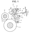
Fig. 1 is a side view of a pile orientation device of a pile fabric loom according to a first preferred embodiment of the present invention, showing the operation of the device during fast picking; -
Fig. 2 is a side view showing the operation of the pile orientation device ofFig. 1 during loose picking; -
Fig. 3 is an exploded perspective view showing the pile orientation device ofFig. 1 ; -
Fig. 4 is a side view showing a pile orientation device for a pile fabric loom according to a second preferred embodiment of the present invention showing the operation of the device during fast picking; -
Fig. 5A is a partially enlarged side view showing a pile orientation device according to another embodiment of the present invention; and -
Fig. 5B is a partially enlarged perspective side view showing a pile orientation device according to yet another embodiment of the present invention. - The following will describe a pile orientation device for a pile fabric loom according to a first preferred embodiment of the present invention with reference to
Figs. 1 through 3 . It is noted that the left and right sides ofFig. 1 correspond to the front and rear sides of the pile fabric loom. Referring toFig. 1 , the pile fabric loom includes apile orientation device 11. Thepile orientation device 11 has acloth guide member 1 and a rockingmember 2 fixedly mounted on ashaft 3. Thecloth guide member 1 is formed in a cylindrical shape and fixed to the top end of the rockingmember 2 and is driven to rock on theshaft 3 in reciprocal back-and-forth direction of arrow A1 by the terry motion (not shown). The rockingmember 2 has aprojection 4 extending therefrom and having a connectingpin 5 inserted through a hole in theprojection 4. The connectingpin 5 moves afell plate 7 and a temple device (not shown) together in the front-and-rear direction of the pile fabric loom through alink 6. Thus, a woven cloth W extending between thecloth guide member 1 and a cloth fell W1 is moved reciprocally in the front-and-rear direction of arrow A2 by the rocking motion of thecloth guide member 1, so that the position of the cloth fell W1 is moved reciprocally in the front-and-rear direction of the pile fabric loom. -
Fig. 1 shows the pile fabric loom during fast picking when thecloth guide member 1 is moved to the rear position thereof and the cloth fell W1 coincides with the beating position of areed 8 of the pile fabric loom.Fig. 2 shows the pile fabric loom during loose picking when thecloth guide member 1 is moved to the front position thereof and the cloth fell W1 is spaced from the beating position of thereed 8 at a predetermined distance. During the operation of the pile fabric loom, loose picking is performed by shedding operation of warp yarns Y and weft insertion in the state ofFig. 2 , and fast picking is performed by shedding operation of warp yarns Y and weft insertion in the state ofFig. 1 . The woven cloth W having piles formed by fast picking is guided toward the winding side of the pile fabric loom by thecloth guide member 1, then moved around a surface roller 9 and aguide roller 10 and wound around a winding roller (not shown). - A
bracket 12 is mounted to a frame (not shown) of the pile fabric loom at a position above thecloth guide member 1. A cylindrical supportingmember 13 extending in the direction of weaving width of the pile fabric loom is fixedly mounted at the opposite ends thereof to thebracket 12 by abolt 15 through a press plate 1.4. Specifically, the supportingmember 13 has elongatedholes elongated holes member 13 to thebracket 12. - The following will describe the
pile orientation device 11 with reference toFig. 3 . A plurality ofleaf springs 16 each having a curved shape is disposed at predetermined spaced intervals in the weaving width direction. Eachleaf spring 16 is fixed at one end thereof to the supportingmember 13 by ascrew 17 and at the other end thereof to a plate-shapedpile orientation member 1$ extending along the weaving width by ascrew 19. Thepile orientation member 1$ is arranged so as to press the woven cloth W on the peripheral surface of thecloth guide member 1 through by the urging force of theleaf spring 16 and mounted on the pile fabric loom without being moved in the front-and-rear direction of the pile fabric loom by the terry motion of thecloth guide member 1. Loosening thebolts 15, the supportingmember 13 may be rotated by virtue of theelongated holes member 13 is rotatable in the circumferential direction of the cylindrical supportingmember 13 when thebolt 15 is loosened. By rotating the supportingmember 13 clockwise inFig. 1 , thepile orientation member 1$ is released from engagement with thecloth guide member 1. Thus, setting-up or repairing operations such as drawing-in of woven cloth or connection of warp yarns may be performed with improved workability. - The
pile orientation member 18 having acontact surface 20 is arranged such that thecontact surface 20 is parallel to a line that is the tangential to thecloth guide member 1 at the contact point thereof during fast picking so that thecontact surface 20 is disposed along the rocking direction of the rockingmember 2 or the moving direction of thecloth guide member 1. Thecontact surface 20 is formed with a length that covers the whole longitudinal moving range L of thecloth guide member 1, as shown inFig. 2 , so as to be constantly pressed against thecloth guide member 1. The peripheral surface of thecloth guide member 1 for guiding the woven cloth W is formed with a curved surface, while thecontact surface 20 of thepile orientation member 18 is formed with a planar surface, so that a wedge-shapedspace 21 is formed between thecloth guide member 1 and thepile orientation member 18 on the upstream side thereof with respect to the moving direction of the woven cloth W or on the advancing side of the woven cloth W during the normal rotation of the pile fabric loom. A similar wedge-shapedspace 22 is also formed on the downstream side thereof with respect to the moving direction of the woven cloth W or on the winding side of the pile fabric loom. Thus, the wedge-shapedspaces cloth guide member 1 and thepile orientation member 18. Thesespaces cloth guide member 1 and thepile orientation member 18. - The following will describe the operation and advantageous effects of the pile orientation device in the pile fabric loom according to the first preferred embodiment of the present invention. During operation of the pile fabric loom, the
cloth guide member 1 is rocked in the longitudinal direction of the pile fabric loom and in a predetermined manner of operation by the terry motion (not shown). - The woven cloth W is moved forward in accordance with the weaving operation and smoothly enter into the wedge-shaped
space 21. In the wedge-shapedspace 21, the piles of the woven cloth W are gradually laid down back by thecontact surface 20 of thepile orientation member 18. At the contacting point between thecontact surface 20 and thecloth guide member 1, the piles of the woven cloth W receive strong pressing force due to the urging force of theleaf springs 16 to be pressed against the woven cloth W. Furthermore, since thecloth guide member 1 is rocked reciprocally over the above longitudinal moving range L shown inFig. 2 by the terry motion, the piles on thecontact surface 20 receives a force due to sliding contact while simultaneously receiving strong pressing force due to the urging force of theleaf spring 16. That is, the piles thus laid down are pressed firmly as if being ironed. - The woven cloth W thus receiving the pile orientation action leaves from the
space 22 and wound stably around the winding roller (not shown) without allowing the piles to raise when passing through the surface roller 9 and theguide roller 10. Thus, the pile fabric loom equipped with thepile orientation device 11 1 having thepile orientation member 18 can produce a woven cloth W whose piles are stably oriented in one direction by the synergetic effects of the strong pressing force against the piles and sliding contact force by terry motion. - If mispicking of weft or yarn breakage of warp yarn Y occurs during weaving operation, the pile fabric loom is driven in reverse direction for repairing. When the pile fabric loom is moved in the reverse direction, the woven cloth W is moved rearward. Since the piles are laid down firmly, the woven cloth W smoothly enters into the wedge-shaped
space 22 without allowing the piles to rise at the contacting point of thepile orientation member 18 by being pulled by thecontact surface 20. Therefore, there is no fear of a defect such as friction mark which may occur when the pile fabric loom is driven in reverse direction. - The first preferred embodiment of the present invention offers the following advantageous effects.
- (1) The
pile orientation device 11 can orient piles in one direction firmly by the synergetic effects of the strong pressing force and sliding contact force by the terry motion. - (2) The woven cloth W is not bent when the woven cloth W is pressed against the rigid
cloth guide member 1 by thepile orientation member 18, so that thepile orientation member 18 can apply the urging force of theleaf spring 16 directly to the woven cloth W, thereby improving the pressing force against the piles. Since theleaf springs 16 are changeable, leaf springs with the desired magnitude of pressing force may be selected depending on types of the woven cloth W to be woven. - (3) Since the
leaf spring 16 can absorb vibration, the desired pressing force against the piles may be kept substantially constant without receiving the influence of vibration generated during weaving operation of the pile fabric loom. - (4) Since the
contact surface 20 of thepile orientation member 18 is disposed along the moving direction of thecloth guide member 1, there is no fear that thecontact surface 20 of thepile orientation member 18 may collide with thecloth guide member 1 rocking by the terry motion and the woven cloth W is damaged or the terry motion is blocked. - The following will describe a second preferred embodiment of the present invention with reference to
Fig. 4 . The second preferred embodiment differs from the first preferred embodiment in that thecloth guide member 1 and thepile orientation member 18 are modified. The same reference numerals are used to denote those components or elements which correspond to the counterparts of the first preferred embodiment and the description thereof will be omitted. - According to the second preferred embodiment of the present invention, the
cylindrical supporting member 23 is fixed to the upper end of the rockingmember 2 and a beam-shapedcloth guide member 24 extending in the cloth width direction is fixed to the supportingmember 23. Thecloth guide member 24 has a flatpressure receiving surface 25 as a cloth guiding surface. A cylindricalpile orientation member 26 is fixed to theleaf springs 16 of thepile orientation device 11 byscrews 19. Thepile orientation member 26 is disposed so as to press the woven cloth W on thepressure receiving surface 25 of thecloth guide member 24. Thus, as in the case of the first preferred embodiment, a wedge-shapedspace 27 and a wedge-shapedspace 28 are formed between thecloth guide member 24 and thepile orientation member 26, and the woven cloth W enters into the wedge-shapedspace 27 and leaves from the wedge-shapedspace 28. - The
cloth guide member 24 during the fast picking is indicated by the solid line and thecloth guide member 24 during the loose picking is indicated by the double-dashed line inFig. 4 , respectively. According to the second preferred embodiment of the present invention, strong pressing force exerted by thepile orientation member 26 against the piles and the sliding contact force generated by terry motion of thecloth guide member 24 are applied to the woven cloth W. Thus, according to the second preferred embodiment of the present invention, the synergetic effects of the strong pressing force and the sliding contact force are obtained, so that the woven cloth W whose piles are oriented in one direction firmly may be woven. Therefore, the same advantageous effects as those of the first preferred embodiment may be obtained. - The present invention is not limited to the first and second preferred embodiments described above, but it may be modified into various alternative embodiments as exemplified below.
- (5) Referring to
Fig. 5A showing a pile orientation device according to an alternative embodiment of the present invention, thepile orientation member 29 fixed to theleaf spring 16 by thescrew 19 is formed to have a substantially plate shape as in the case of the first embodiment, but thecontact surface 30 is formed on the upstream side thereof with respect to the moving direction of the woven cloth W with anarcuate surface 31. The provision of thearcuate surface 31 permits the woven cloth W to move smoothly past the pressing point between thepile orientation member 29 and thecloth guide member 1. - (6) Referring to
Fig. 5B showing a pile orientation device according to another alternative embodiment of the present invention, thepile orientation member 32 fixed to theleaf spring 16 by thescrew 19 is formed to have a plate shape and thecontact surface 33 of thepile orientation member 32 is formed on the upstream and downstream side thereof with respect to the moving direction of the woven cloth W witharcuate surfaces arcuate surface 35 of thepile orientation member 32 permits the woven cloth W to smoothly enter into between thepile orientation member 32 and thecloth guide member 1 when the pile fabric loom is driven in reverse direction. Thus, the woven cloth W being moved reverse is prevented from damage.. - (7) The
pile orientation members leaf spring 16, but a pile orientation member may be formed such that the urging force is provided by its own weight. - (8) Forming a plate-shaped pile orientation member with an arcuate surface such as 31 shown in
Fig. 5A or with arcuate surfaces such as 34, 35 shown inFig. 5B , thecloth guide member 1 may have a planar guide surface for guiding the woven cloth W such as thecloth guide member 24 shown inFig. 4 . - (9) The
pile orientation member cloth guide member leaf spring 16 or its own weight, but may be formed as exemplified below. Thepile orientation member cloth guide member cloth guide member pile orientation member cloth guide member - (10) The
cloth guide member - (11) According to the present invention, the structure wherein the
contact surface pile orientation member cloth guide member cloth guide member pile orientation member cloth guide member pile orientation member cloth guide member - A pile orientation device for pile fabric loom includes a cloth guide member and a pile orientation member. The pile fabric loom for producing a woven cloth has a terry motion. The woven cloth is moved reciprocally in the front-and-rear direction of the pile fabric loom to shift a cloth fell position by the terry motion and piles are formed in the woven cloth by the terry motion. The cloth guide member is movable reciprocally in the front-and-rear direction of the pile fabric loom by the terry motion and guides the woven cloth toward the winding side of the pile fabric loom. The pile orientation member is used for pressing the woven cloth on the cloth guide member. The pile orientation member is mounted on the pile fabric loom without being moved in the front-and-rear direction of the pile fabric loom by the terry motion.
Claims (10)
- A pile orientation device (11) for pile fabric loom, the pile fabric loom for producing a woven cloth (W) having a terry motion, the woven cloth (W) moved reciprocally in the front-and-rear direction of the pile fabric loom to shift a position of cloth fell (W1) by the terry motion, piles formed in the woven cloth (W) by the terry motion, the pile orientation device (11) comprising: i
a cloth guide member (1, 24) being movable reciprocally in the front-and-rear direction of the pile fabric loom by the terry motion and guiding the woven cloth (W) toward the winding side of the pile fabric loom,
characterized in that the pile orientation device (11) includes a pile orientation member (18, 26, 29, 32) for pressing the woven cloth (W) on the cloth guide member (1, 24), and the pile orientation member (18, 26, 29, 32) is mounted on the pile fabric loom without being moved in the front-and-rear direction of the pile fabric loom by the terry motion. - The pile orientation device (11) according to claim 1, characterized in that the pile orientation member (18, 26, 29, 32) having a contact surface (20, 30, 33) pressing the woven cloth (W) on the cloth guide member (1, 24), the contact surface (20, 30, 33) is disposed along the moving direction of the cloth guide member (1, 24).
- The pile orientation device (11) according to claim 1 or 2, characterized in that the contact surface (20, 30, 33) has a length covering a whole longitudinal moving range (L) of the cloth guide member (1, 24).
- The pile orientation device (11) according to any one of claims 1 through 3, characterized in that a wedge-shaped space (21, 22, 27, 28) is formed between the contact surface (20, 30, 33) and the cloth guide member (1, 24), and the woven cloth (W) enters into the wedge-shaped space (21, 22, 27, 28).
- The pile orientation device (11) according to claim 4, characterized in that the wedge shaped space (21, 22, 27, 28) is formed on the upstream side of the woven cloth (W) and the downstream side of the woven cloth (W), respectively, in relation to the contact surface (20, 30, 33) and the cloth guide member (1, 24).
- The pile orientation device (11) according to any one of claims 1 through 5, characterized in that any one of the surface of the cloth guide member (1, 24) and the contact surface (20, 30, 33) is formed with a curved surface and the other is formed with a planar surface.
- The pile orientation device (11) according to any one of claims 1 through 6, characterized in that the pile orientation member (18, 26, 29, 32) is pressed against the cloth guide member (1, 24) by urging force.
- The pile orientation device (11) according to claim 7, characterized in that the urging force is generated by the leaf spring (16) or the weight of the pile orientation member (18, 26, 29, 32) itself.
- The pile orientation device (11) according to any one of claims 1 through 8, characterized in that the pile orientation member (18, 26, 29, 32) is fixed so as to be spaced apart from the cloth guide member (1, 24) at a predetermined interval such that the pile orientation member (18, 26, 29, 32) presses the woven cloth (W) on the cloth guide member (1, 24) by reaction force of the pulling function of the woven cloth (W).
- The pile orientation device (11) according to any one of claims 1 through 9, characterized in that the pile orientation device (11) has a cylindrical supporting member (13), the cylindrical supporting member (13) is disposed so as to extend in the direction of weaving width of the pile fabric loom, fixedly mounted to a frame of the pile fabric loom by a bolt (15), and rotatable in the circumferential direction of the cylindrical supporting member (13) when the bolt (15) is loosened, and the pile orientation member (18, 26, 29, 32) is supported by the cylindrical supporting member (13).
Applications Claiming Priority (1)
| Application Number | Priority Date | Filing Date | Title |
|---|---|---|---|
| JP2010003514A JP5644113B2 (en) | 2010-01-12 | 2010-01-12 | Pile aligner in pile loom |
Publications (2)
| Publication Number | Publication Date |
|---|---|
| EP2343404A1 true EP2343404A1 (en) | 2011-07-13 |
| EP2343404B1 EP2343404B1 (en) | 2013-06-05 |
Family
ID=43822587
Family Applications (1)
| Application Number | Title | Priority Date | Filing Date |
|---|---|---|---|
| EP20100196125 Not-in-force EP2343404B1 (en) | 2010-01-12 | 2010-12-21 | Pile orientation device for pile fabric loom |
Country Status (3)
| Country | Link |
|---|---|
| EP (1) | EP2343404B1 (en) |
| JP (1) | JP5644113B2 (en) |
| CN (1) | CN102127834B (en) |
Cited By (1)
| Publication number | Priority date | Publication date | Assignee | Title |
|---|---|---|---|---|
| CN106012212A (en) * | 2016-07-29 | 2016-10-12 | 鲁丰织染有限公司 | Formal dress fabric weaving method and special temple for weaving of fabrics of formal dress varieties |
Families Citing this family (1)
| Publication number | Priority date | Publication date | Assignee | Title |
|---|---|---|---|---|
| CN106167948A (en) * | 2016-08-31 | 2016-11-30 | 山东日发纺织机械有限公司 | A kind of loom Bo Mao mechanism |
Citations (4)
| Publication number | Priority date | Publication date | Assignee | Title |
|---|---|---|---|---|
| GB1361312A (en) * | 1971-03-17 | 1974-07-24 | Sulzer Ag | Looms for making terry cloth |
| JPS6451680A (en) | 1987-08-22 | 1989-02-27 | Sumitomo Electric Industries | Oxide ceramics laminated layer structure and its manufacture |
| JPH10273854A (en) | 1997-03-28 | 1998-10-13 | Toyota Autom Loom Works Ltd | Pile arranging apparatus in pile weaving machine |
| JP2001006878A (en) | 1999-06-22 | 2001-01-12 | Matsushita Electric Ind Co Ltd | Thin film EL element and driving method thereof |
Family Cites Families (6)
| Publication number | Priority date | Publication date | Assignee | Title |
|---|---|---|---|---|
| JPH0640601Y2 (en) * | 1987-09-18 | 1994-10-26 | 津田駒工業株式会社 | Pile aligner |
| JPH0187182U (en) * | 1987-11-27 | 1989-06-08 | ||
| JPH01183553A (en) * | 1988-01-13 | 1989-07-21 | Kikuo Niida | Towel loom |
| JPH1121743A (en) * | 1997-07-07 | 1999-01-26 | Tsudakoma Corp | Pile formation system |
| JP3841158B2 (en) * | 2001-11-22 | 2006-11-01 | 株式会社日立製作所 | Rubbing cloth for orientation treatment |
| DE502004004436D1 (en) * | 2004-06-18 | 2007-09-06 | Schoenherr Textilmaschinenbau | Process and apparatus for forming jacquard patterned pile warp yarns on a double pile loom |
-
2010
- 2010-01-12 JP JP2010003514A patent/JP5644113B2/en not_active Expired - Fee Related
- 2010-12-21 EP EP20100196125 patent/EP2343404B1/en not_active Not-in-force
-
2011
- 2011-01-11 CN CN 201110004396 patent/CN102127834B/en not_active Expired - Fee Related
Patent Citations (4)
| Publication number | Priority date | Publication date | Assignee | Title |
|---|---|---|---|---|
| GB1361312A (en) * | 1971-03-17 | 1974-07-24 | Sulzer Ag | Looms for making terry cloth |
| JPS6451680A (en) | 1987-08-22 | 1989-02-27 | Sumitomo Electric Industries | Oxide ceramics laminated layer structure and its manufacture |
| JPH10273854A (en) | 1997-03-28 | 1998-10-13 | Toyota Autom Loom Works Ltd | Pile arranging apparatus in pile weaving machine |
| JP2001006878A (en) | 1999-06-22 | 2001-01-12 | Matsushita Electric Ind Co Ltd | Thin film EL element and driving method thereof |
Cited By (2)
| Publication number | Priority date | Publication date | Assignee | Title |
|---|---|---|---|---|
| CN106012212A (en) * | 2016-07-29 | 2016-10-12 | 鲁丰织染有限公司 | Formal dress fabric weaving method and special temple for weaving of fabrics of formal dress varieties |
| CN106012212B (en) * | 2016-07-29 | 2018-04-13 | 鲁丰织染有限公司 | Ceremonial dress face fabric method for weaving and the special temple of full dress kind face weave |
Also Published As
| Publication number | Publication date |
|---|---|
| JP5644113B2 (en) | 2014-12-24 |
| EP2343404B1 (en) | 2013-06-05 |
| CN102127834A (en) | 2011-07-20 |
| JP2011144456A (en) | 2011-07-28 |
| CN102127834B (en) | 2013-09-04 |
Similar Documents
| Publication | Publication Date | Title |
|---|---|---|
| EP2524074B1 (en) | Method and device for the manufacturing of fabrics with at least two different pile heights in a same pile row | |
| EP2343404B1 (en) | Pile orientation device for pile fabric loom | |
| US3952778A (en) | Selvage forming device | |
| EP2902536A1 (en) | Warp bending device for loom | |
| CN101748552A (en) | Pile fabric loom having pile warp tension adjuster | |
| CN110195287B (en) | Selvedge device of small weft density glass fiber air jet loom | |
| CN203498586U (en) | Warp feeding device applicable to weaving of non-bending fabrics | |
| CN105008604B (en) | Heald for loom, heald frame member and loom | |
| US6386241B1 (en) | Leno weaving | |
| CS597290A3 (en) | Apparatus for leno weaving of a cloth selvedge in a loom | |
| CN210711921U (en) | Reed device | |
| US3620260A (en) | Loom tension-frame holding the woven fabric over its entire width | |
| JP2006336183A (en) | Woven fabric-producing loom for water jet loom | |
| JP2022116386A (en) | Loom reed | |
| CN214736433U (en) | Loom warp stop frame trailing arm | |
| CN120797293A (en) | Production equipment of heating cloth | |
| CN116536840B (en) | Staggered warp yarn pattern weaving device | |
| KR101180036B1 (en) | A device generating tension in the weft direction for a weft-straightener | |
| US20060021667A1 (en) | Driving system for terry motion members in cloth-shifting-type pile loom | |
| WO2017036853A1 (en) | Deflecting device for a weaving machine and method for manufacturing a deflecting device | |
| CN214004956U (en) | Reed for rapier loom | |
| CN216473725U (en) | Curl clamping mechanism and three-dimensional circular loom | |
| CN1856609B (en) | Guiding element for a gripper strip | |
| CN210341239U (en) | Detection mechanism for machining position | |
| JP2006045754A (en) | Reed for high-speed air jet loom |
Legal Events
| Date | Code | Title | Description |
|---|---|---|---|
| PUAI | Public reference made under article 153(3) epc to a published international application that has entered the european phase |
Free format text: ORIGINAL CODE: 0009012 |
|
| 17P | Request for examination filed |
Effective date: 20101221 |
|
| AK | Designated contracting states |
Kind code of ref document: A1 Designated state(s): AL AT BE BG CH CY CZ DE DK EE ES FI FR GB GR HR HU IE IS IT LI LT LU LV MC MK MT NL NO PL PT RO RS SE SI SK SM TR |
|
| AX | Request for extension of the european patent |
Extension state: BA ME |
|
| GRAP | Despatch of communication of intention to grant a patent |
Free format text: ORIGINAL CODE: EPIDOSNIGR1 |
|
| GRAS | Grant fee paid |
Free format text: ORIGINAL CODE: EPIDOSNIGR3 |
|
| GRAA | (expected) grant |
Free format text: ORIGINAL CODE: 0009210 |
|
| AK | Designated contracting states |
Kind code of ref document: B1 Designated state(s): AL AT BE BG CH CY CZ DE DK EE ES FI FR GB GR HR HU IE IS IT LI LT LU LV MC MK MT NL NO PL PT RO RS SE SI SK SM TR |
|
| REG | Reference to a national code |
Ref country code: GB Ref legal event code: FG4D |
|
| REG | Reference to a national code |
Ref country code: CH Ref legal event code: EP |
|
| REG | Reference to a national code |
Ref country code: AT Ref legal event code: REF Ref document number: 615749 Country of ref document: AT Kind code of ref document: T Effective date: 20130615 |
|
| REG | Reference to a national code |
Ref country code: IE Ref legal event code: FG4D |
|
| REG | Reference to a national code |
Ref country code: DE Ref legal event code: R096 Ref document number: 602010007545 Country of ref document: DE Effective date: 20130801 |
|
| REG | Reference to a national code |
Ref country code: AT Ref legal event code: MK05 Ref document number: 615749 Country of ref document: AT Kind code of ref document: T Effective date: 20130605 |
|
| PG25 | Lapsed in a contracting state [announced via postgrant information from national office to epo] |
Ref country code: SE Free format text: LAPSE BECAUSE OF FAILURE TO SUBMIT A TRANSLATION OF THE DESCRIPTION OR TO PAY THE FEE WITHIN THE PRESCRIBED TIME-LIMIT Effective date: 20130605 Ref country code: LT Free format text: LAPSE BECAUSE OF FAILURE TO SUBMIT A TRANSLATION OF THE DESCRIPTION OR TO PAY THE FEE WITHIN THE PRESCRIBED TIME-LIMIT Effective date: 20130605 Ref country code: ES Free format text: LAPSE BECAUSE OF FAILURE TO SUBMIT A TRANSLATION OF THE DESCRIPTION OR TO PAY THE FEE WITHIN THE PRESCRIBED TIME-LIMIT Effective date: 20130916 Ref country code: FI Free format text: LAPSE BECAUSE OF FAILURE TO SUBMIT A TRANSLATION OF THE DESCRIPTION OR TO PAY THE FEE WITHIN THE PRESCRIBED TIME-LIMIT Effective date: 20130605 Ref country code: NO Free format text: LAPSE BECAUSE OF FAILURE TO SUBMIT A TRANSLATION OF THE DESCRIPTION OR TO PAY THE FEE WITHIN THE PRESCRIBED TIME-LIMIT Effective date: 20130905 Ref country code: SI Free format text: LAPSE BECAUSE OF FAILURE TO SUBMIT A TRANSLATION OF THE DESCRIPTION OR TO PAY THE FEE WITHIN THE PRESCRIBED TIME-LIMIT Effective date: 20130605 Ref country code: GR Free format text: LAPSE BECAUSE OF FAILURE TO SUBMIT A TRANSLATION OF THE DESCRIPTION OR TO PAY THE FEE WITHIN THE PRESCRIBED TIME-LIMIT Effective date: 20130906 Ref country code: AT Free format text: LAPSE BECAUSE OF FAILURE TO SUBMIT A TRANSLATION OF THE DESCRIPTION OR TO PAY THE FEE WITHIN THE PRESCRIBED TIME-LIMIT Effective date: 20130605 |
|
| REG | Reference to a national code |
Ref country code: NL Ref legal event code: VDEP Effective date: 20130605 |
|
| REG | Reference to a national code |
Ref country code: LT Ref legal event code: MG4D |
|
| PG25 | Lapsed in a contracting state [announced via postgrant information from national office to epo] |
Ref country code: HR Free format text: LAPSE BECAUSE OF FAILURE TO SUBMIT A TRANSLATION OF THE DESCRIPTION OR TO PAY THE FEE WITHIN THE PRESCRIBED TIME-LIMIT Effective date: 20130605 Ref country code: BG Free format text: LAPSE BECAUSE OF FAILURE TO SUBMIT A TRANSLATION OF THE DESCRIPTION OR TO PAY THE FEE WITHIN THE PRESCRIBED TIME-LIMIT Effective date: 20130905 Ref country code: RS Free format text: LAPSE BECAUSE OF FAILURE TO SUBMIT A TRANSLATION OF THE DESCRIPTION OR TO PAY THE FEE WITHIN THE PRESCRIBED TIME-LIMIT Effective date: 20130605 |
|
| PG25 | Lapsed in a contracting state [announced via postgrant information from national office to epo] |
Ref country code: LV Free format text: LAPSE BECAUSE OF FAILURE TO SUBMIT A TRANSLATION OF THE DESCRIPTION OR TO PAY THE FEE WITHIN THE PRESCRIBED TIME-LIMIT Effective date: 20130605 |
|
| PG25 | Lapsed in a contracting state [announced via postgrant information from national office to epo] |
Ref country code: EE Free format text: LAPSE BECAUSE OF FAILURE TO SUBMIT A TRANSLATION OF THE DESCRIPTION OR TO PAY THE FEE WITHIN THE PRESCRIBED TIME-LIMIT Effective date: 20130605 Ref country code: SK Free format text: LAPSE BECAUSE OF FAILURE TO SUBMIT A TRANSLATION OF THE DESCRIPTION OR TO PAY THE FEE WITHIN THE PRESCRIBED TIME-LIMIT Effective date: 20130605 Ref country code: IS Free format text: LAPSE BECAUSE OF FAILURE TO SUBMIT A TRANSLATION OF THE DESCRIPTION OR TO PAY THE FEE WITHIN THE PRESCRIBED TIME-LIMIT Effective date: 20131005 Ref country code: CZ Free format text: LAPSE BECAUSE OF FAILURE TO SUBMIT A TRANSLATION OF THE DESCRIPTION OR TO PAY THE FEE WITHIN THE PRESCRIBED TIME-LIMIT Effective date: 20130605 Ref country code: PT Free format text: LAPSE BECAUSE OF FAILURE TO SUBMIT A TRANSLATION OF THE DESCRIPTION OR TO PAY THE FEE WITHIN THE PRESCRIBED TIME-LIMIT Effective date: 20131007 |
|
| PG25 | Lapsed in a contracting state [announced via postgrant information from national office to epo] |
Ref country code: NL Free format text: LAPSE BECAUSE OF FAILURE TO SUBMIT A TRANSLATION OF THE DESCRIPTION OR TO PAY THE FEE WITHIN THE PRESCRIBED TIME-LIMIT Effective date: 20130605 Ref country code: RO Free format text: LAPSE BECAUSE OF FAILURE TO SUBMIT A TRANSLATION OF THE DESCRIPTION OR TO PAY THE FEE WITHIN THE PRESCRIBED TIME-LIMIT Effective date: 20130605 Ref country code: PL Free format text: LAPSE BECAUSE OF FAILURE TO SUBMIT A TRANSLATION OF THE DESCRIPTION OR TO PAY THE FEE WITHIN THE PRESCRIBED TIME-LIMIT Effective date: 20130605 |
|
| PLBE | No opposition filed within time limit |
Free format text: ORIGINAL CODE: 0009261 |
|
| STAA | Information on the status of an ep patent application or granted ep patent |
Free format text: STATUS: NO OPPOSITION FILED WITHIN TIME LIMIT |
|
| PG25 | Lapsed in a contracting state [announced via postgrant information from national office to epo] |
Ref country code: DK Free format text: LAPSE BECAUSE OF FAILURE TO SUBMIT A TRANSLATION OF THE DESCRIPTION OR TO PAY THE FEE WITHIN THE PRESCRIBED TIME-LIMIT Effective date: 20130605 |
|
| 26N | No opposition filed |
Effective date: 20140306 |
|
| PG25 | Lapsed in a contracting state [announced via postgrant information from national office to epo] |
Ref country code: IT Free format text: LAPSE BECAUSE OF FAILURE TO SUBMIT A TRANSLATION OF THE DESCRIPTION OR TO PAY THE FEE WITHIN THE PRESCRIBED TIME-LIMIT Effective date: 20130605 |
|
| REG | Reference to a national code |
Ref country code: DE Ref legal event code: R097 Ref document number: 602010007545 Country of ref document: DE Effective date: 20140306 |
|
| PG25 | Lapsed in a contracting state [announced via postgrant information from national office to epo] |
Ref country code: MC Free format text: LAPSE BECAUSE OF FAILURE TO SUBMIT A TRANSLATION OF THE DESCRIPTION OR TO PAY THE FEE WITHIN THE PRESCRIBED TIME-LIMIT Effective date: 20130605 |
|
| PG25 | Lapsed in a contracting state [announced via postgrant information from national office to epo] |
Ref country code: LU Free format text: LAPSE BECAUSE OF FAILURE TO SUBMIT A TRANSLATION OF THE DESCRIPTION OR TO PAY THE FEE WITHIN THE PRESCRIBED TIME-LIMIT Effective date: 20131221 |
|
| REG | Reference to a national code |
Ref country code: IE Ref legal event code: MM4A |
|
| REG | Reference to a national code |
Ref country code: FR Ref legal event code: ST Effective date: 20140829 |
|
| PG25 | Lapsed in a contracting state [announced via postgrant information from national office to epo] |
Ref country code: IE Free format text: LAPSE BECAUSE OF NON-PAYMENT OF DUE FEES Effective date: 20131221 |
|
| PG25 | Lapsed in a contracting state [announced via postgrant information from national office to epo] |
Ref country code: FR Free format text: LAPSE BECAUSE OF NON-PAYMENT OF DUE FEES Effective date: 20131231 |
|
| PG25 | Lapsed in a contracting state [announced via postgrant information from national office to epo] |
Ref country code: SM Free format text: LAPSE BECAUSE OF FAILURE TO SUBMIT A TRANSLATION OF THE DESCRIPTION OR TO PAY THE FEE WITHIN THE PRESCRIBED TIME-LIMIT Effective date: 20130605 |
|
| PG25 | Lapsed in a contracting state [announced via postgrant information from national office to epo] |
Ref country code: CY Free format text: LAPSE BECAUSE OF FAILURE TO SUBMIT A TRANSLATION OF THE DESCRIPTION OR TO PAY THE FEE WITHIN THE PRESCRIBED TIME-LIMIT Effective date: 20130605 Ref country code: TR Free format text: LAPSE BECAUSE OF FAILURE TO SUBMIT A TRANSLATION OF THE DESCRIPTION OR TO PAY THE FEE WITHIN THE PRESCRIBED TIME-LIMIT Effective date: 20130605 |
|
| PG25 | Lapsed in a contracting state [announced via postgrant information from national office to epo] |
Ref country code: HU Free format text: LAPSE BECAUSE OF FAILURE TO SUBMIT A TRANSLATION OF THE DESCRIPTION OR TO PAY THE FEE WITHIN THE PRESCRIBED TIME-LIMIT; INVALID AB INITIO Effective date: 20101221 Ref country code: MK Free format text: LAPSE BECAUSE OF FAILURE TO SUBMIT A TRANSLATION OF THE DESCRIPTION OR TO PAY THE FEE WITHIN THE PRESCRIBED TIME-LIMIT Effective date: 20130605 |
|
| REG | Reference to a national code |
Ref country code: CH Ref legal event code: PL |
|
| GBPC | Gb: european patent ceased through non-payment of renewal fee |
Effective date: 20141221 |
|
| PG25 | Lapsed in a contracting state [announced via postgrant information from national office to epo] |
Ref country code: MT Free format text: LAPSE BECAUSE OF FAILURE TO SUBMIT A TRANSLATION OF THE DESCRIPTION OR TO PAY THE FEE WITHIN THE PRESCRIBED TIME-LIMIT Effective date: 20130605 |
|
| PG25 | Lapsed in a contracting state [announced via postgrant information from national office to epo] |
Ref country code: LI Free format text: LAPSE BECAUSE OF NON-PAYMENT OF DUE FEES Effective date: 20141231 Ref country code: CH Free format text: LAPSE BECAUSE OF NON-PAYMENT OF DUE FEES Effective date: 20141231 Ref country code: GB Free format text: LAPSE BECAUSE OF NON-PAYMENT OF DUE FEES Effective date: 20141221 |
|
| PG25 | Lapsed in a contracting state [announced via postgrant information from national office to epo] |
Ref country code: AL Free format text: LAPSE BECAUSE OF FAILURE TO SUBMIT A TRANSLATION OF THE DESCRIPTION OR TO PAY THE FEE WITHIN THE PRESCRIBED TIME-LIMIT Effective date: 20130605 |
|
| PGFP | Annual fee paid to national office [announced via postgrant information from national office to epo] |
Ref country code: DE Payment date: 20181211 Year of fee payment: 9 |
|
| PGFP | Annual fee paid to national office [announced via postgrant information from national office to epo] |
Ref country code: BE Payment date: 20181119 Year of fee payment: 9 |
|
| REG | Reference to a national code |
Ref country code: DE Ref legal event code: R119 Ref document number: 602010007545 Country of ref document: DE |
|
| REG | Reference to a national code |
Ref country code: BE Ref legal event code: MM Effective date: 20191231 |
|
| PG25 | Lapsed in a contracting state [announced via postgrant information from national office to epo] |
Ref country code: DE Free format text: LAPSE BECAUSE OF NON-PAYMENT OF DUE FEES Effective date: 20200701 |
|
| PG25 | Lapsed in a contracting state [announced via postgrant information from national office to epo] |
Ref country code: BE Free format text: LAPSE BECAUSE OF NON-PAYMENT OF DUE FEES Effective date: 20191231 |