EP2342546B1 - Vorrichtung zur bestimmung und/oder überwachung eines drucks - Google Patents
Vorrichtung zur bestimmung und/oder überwachung eines drucks Download PDFInfo
- Publication number
- EP2342546B1 EP2342546B1 EP09745016.7A EP09745016A EP2342546B1 EP 2342546 B1 EP2342546 B1 EP 2342546B1 EP 09745016 A EP09745016 A EP 09745016A EP 2342546 B1 EP2342546 B1 EP 2342546B1
- Authority
- EP
- European Patent Office
- Prior art keywords
- pressure
- membrane
- acoustic sensor
- evaluation unit
- signals
- Prior art date
- Legal status (The legal status is an assumption and is not a legal conclusion. Google has not performed a legal analysis and makes no representation as to the accuracy of the status listed.)
- Not-in-force
Links
- 238000012544 monitoring process Methods 0.000 title claims description 5
- 239000012528 membrane Substances 0.000 claims description 36
- 238000011156 evaluation Methods 0.000 claims description 17
- 238000001514 detection method Methods 0.000 claims description 4
- 239000000919 ceramic Substances 0.000 description 20
- 238000000034 method Methods 0.000 description 10
- 229910052751 metal Inorganic materials 0.000 description 9
- 239000002184 metal Substances 0.000 description 9
- 239000007788 liquid Substances 0.000 description 3
- 238000001228 spectrum Methods 0.000 description 3
- 230000002123 temporal effect Effects 0.000 description 3
- RTAQQCXQSZGOHL-UHFFFAOYSA-N Titanium Chemical compound [Ti] RTAQQCXQSZGOHL-UHFFFAOYSA-N 0.000 description 2
- 229910010293 ceramic material Inorganic materials 0.000 description 2
- 230000001419 dependent effect Effects 0.000 description 2
- 238000012423 maintenance Methods 0.000 description 2
- 238000005259 measurement Methods 0.000 description 2
- 239000011224 oxide ceramic Substances 0.000 description 2
- 238000005476 soldering Methods 0.000 description 2
- 239000010935 stainless steel Substances 0.000 description 2
- 229910001220 stainless steel Inorganic materials 0.000 description 2
- 239000010936 titanium Substances 0.000 description 2
- 229910052719 titanium Inorganic materials 0.000 description 2
- 230000009466 transformation Effects 0.000 description 2
- 229910000505 Al2TiO5 Inorganic materials 0.000 description 1
- PNEYBMLMFCGWSK-UHFFFAOYSA-N Alumina Chemical compound [O-2].[O-2].[O-2].[Al+3].[Al+3] PNEYBMLMFCGWSK-UHFFFAOYSA-N 0.000 description 1
- 229910001374 Invar Inorganic materials 0.000 description 1
- 229910000990 Ni alloy Inorganic materials 0.000 description 1
- 229910045601 alloy Inorganic materials 0.000 description 1
- 239000000956 alloy Substances 0.000 description 1
- 238000009530 blood pressure measurement Methods 0.000 description 1
- 239000003990 capacitor Substances 0.000 description 1
- 230000007797 corrosion Effects 0.000 description 1
- 238000005260 corrosion Methods 0.000 description 1
- 238000005336 cracking Methods 0.000 description 1
- 238000011161 development Methods 0.000 description 1
- 230000018109 developmental process Effects 0.000 description 1
- 238000003745 diagnosis Methods 0.000 description 1
- 230000007613 environmental effect Effects 0.000 description 1
- 239000007789 gas Substances 0.000 description 1
- 239000011521 glass Substances 0.000 description 1
- 229910000833 kovar Inorganic materials 0.000 description 1
- 238000003754 machining Methods 0.000 description 1
- 238000004519 manufacturing process Methods 0.000 description 1
- 150000002739 metals Chemical class 0.000 description 1
- 229910052574 oxide ceramic Inorganic materials 0.000 description 1
- TWNQGVIAIRXVLR-UHFFFAOYSA-N oxo(oxoalumanyloxy)alumane Chemical compound O=[Al]O[Al]=O TWNQGVIAIRXVLR-UHFFFAOYSA-N 0.000 description 1
- RVTZCBVAJQQJTK-UHFFFAOYSA-N oxygen(2-);zirconium(4+) Chemical compound [O-2].[O-2].[Zr+4] RVTZCBVAJQQJTK-UHFFFAOYSA-N 0.000 description 1
- AABBHSMFGKYLKE-SNAWJCMRSA-N propan-2-yl (e)-but-2-enoate Chemical compound C\C=C\C(=O)OC(C)C AABBHSMFGKYLKE-SNAWJCMRSA-N 0.000 description 1
- 230000035939 shock Effects 0.000 description 1
- HBMJWWWQQXIZIP-UHFFFAOYSA-N silicon carbide Chemical compound [Si+]#[C-] HBMJWWWQQXIZIP-UHFFFAOYSA-N 0.000 description 1
- 229910010271 silicon carbide Inorganic materials 0.000 description 1
- 229910001928 zirconium oxide Inorganic materials 0.000 description 1
Images
Classifications
-
- G—PHYSICS
- G01—MEASURING; TESTING
- G01L—MEASURING FORCE, STRESS, TORQUE, WORK, MECHANICAL POWER, MECHANICAL EFFICIENCY, OR FLUID PRESSURE
- G01L19/00—Details of, or accessories for, apparatus for measuring steady or quasi-steady pressure of a fluent medium insofar as such details or accessories are not special to particular types of pressure gauges
- G01L19/0092—Pressure sensor associated with other sensors, e.g. for measuring acceleration or temperature
-
- G—PHYSICS
- G01—MEASURING; TESTING
- G01N—INVESTIGATING OR ANALYSING MATERIALS BY DETERMINING THEIR CHEMICAL OR PHYSICAL PROPERTIES
- G01N29/00—Investigating or analysing materials by the use of ultrasonic, sonic or infrasonic waves; Visualisation of the interior of objects by transmitting ultrasonic or sonic waves through the object
- G01N29/14—Investigating or analysing materials by the use of ultrasonic, sonic or infrasonic waves; Visualisation of the interior of objects by transmitting ultrasonic or sonic waves through the object using acoustic emission techniques
-
- G—PHYSICS
- G01—MEASURING; TESTING
- G01N—INVESTIGATING OR ANALYSING MATERIALS BY DETERMINING THEIR CHEMICAL OR PHYSICAL PROPERTIES
- G01N2291/00—Indexing codes associated with group G01N29/00
- G01N2291/26—Scanned objects
- G01N2291/269—Various geometry objects
- G01N2291/2697—Wafer or (micro)electronic parts
Definitions
- the invention relates to a device for determining and / or monitoring a pressure, with at least one pressure transducer, which converts the pressure into an electrical signal. Furthermore, the invention relates to a device for determining and / or monitoring a process variable, with at least one sensor unit, which determines and / or monitors the process variable.
- Pressure gauges are widely used in process instrumentation to measure the pressure of process media, which may be liquids, gases or vapors.
- such measuring devices or pressure sensors comprise a pressure measuring cell or a pressure transducer, which generally has a main body and an elastic membrane.
- the base body and the membrane consist of a ceramic or at least the membrane consists at least partially of a metal.
- Possible combinations of membrane and base body are, for example, ceramic / ceramic, metal / ceramic or metal / metal with dielectric elements consisting of the ceramic or a glass.
- the soldering process of metal on ceramic is known and can be realized, for example, for a combination of titanium / alumina ceramic (or special alloys such as Kovar instead of titanium).
- a dielectric ceramic of aluminum titanate with a very low coefficient of expansion with a nickel alloy Invar or a silicon carbide ceramic in the soldering process.
- Another embodiment consists in a stainless steel body welded to a stainless steel body.
- a space for an insulating element with the measuring electrodes is preferably provided in this embodiment.
- a flat recess is usually provided, which is also referred to as a membrane bed and is covered by the membrane.
- the membrane is pressurized by the Process medium applied, and the deformation or the mechanical stress in the elastic membrane, which is determined, for example, capacitive or piezoresistive, is a measure of the pressure (see, for example, the published patent application DE 39 01 492 ).
- cracking in the membrane can be the cause of cell failure.
- the thickness of such membranes is dependent on the measuring range of the pressure and is usually between about 0.1 and 2 mm. It is known that, in contrast to metals, ceramic materials can break very quickly due to their brittleness and the resulting lack of plastic deformability, when the mechanical stress reaches the breaking point.
- the cause of breakage of the membrane may be microscopic cracks in the ceramic which have reached supercritical growth under stress. In some manufacturing steps, such as hard machining, cracks can be induced, which can not be recognized due to their size. Another cause of critical crack growth may be local overloading of components due to an unfavorable combination of the thermal gradient during a thermal shock with simultaneous pressure or vacuum loading.
- the measuring cells can thus be mechanically and thermally overloaded in applications and react to this with crack growth. Cracks are detected in extreme cases by an associated leakage, which sometimes costly maintenance is required. In the case of metallic membranes, it is furthermore possible for plastic deformation to occur as a result of overpressure, which leads to a significant measurement deviation.
- a sacrificial membrane has been proposed for the detection of a membrane rupture, which is damaged by a corrosion attack or other critical events. The failure of the victim cell serves as a sign that the measuring cell is also damaged or is about to be damaged.
- the publication US 2007/0073417 A1 describes a pressure sensor which is coupled to an acoustic sensor whose output signal is combined with that of the pressure sensor.
- the acoustic sensor measures the pressure of a liquid based on the pressure-dependent propagation time of acoustic signals in liquids.
- the invention has for its object to provide a pressure transmitter, in which a fraction of the membrane or a plastic deformation is detected.
- the object is achieved by the device according to claim 1.
- the inventive device for determining and monitoring a pressure comprises at least one pressure transducer, which converts the pressure into an electrical signal, wherein the pressure transducer has at least one membrane, which can be acted upon by the pressure, wherein at least one acoustic sensor is provided, which receives acoustic signals and converted into electrical signals, wherein the acoustic sensor is mechanically and / or acoustically coupled to the pressure transducer, wherein at least one evaluation unit is provided which evaluates the electrical signals of the acoustic sensor with respect to a breakage detection or to a plastic deformation of the membrane of the pressure transducer ,
- an already known pressure sensor is extended by an acoustic sensor.
- the pressure transducer consists at least partially of a ceramic and / or of a metal.
- the additional sensor makes an acoustic diagnosis, which refers either to the break or to the plastic deformation. It has been found, in particular, that ceramic materials, such as aluminum oxide ceramics or zirconium oxide ceramics, generate clear acoustic signals shortly before a complete rupture of a membrane. Such signals originate from microscopic fractures in the ceramic grains and according to the invention with an acoustic sensor added.
- the frequency of the signals may be in a range between 50 kHz and 3 MHz.
- the acoustic sensor is mounted on the base body of the pressure transducer.
- the actual mounting position of the acoustic sensor is not critical, since the acoustic signals of the said frequencies propagate well in such a ceramic body, in particular in the case of a ceramic base body.
- the membrane In use, the membrane is exposed to the process pressure or medium to be measured.
- the membrane consists in particular in one embodiment of a ceramic. In a further embodiment, the membrane consists of a metal.
- An embodiment provides that the evaluation unit evaluates the electrical signals of the acoustic sensor with respect to a breakage detection of the membrane of the pressure transducer.
- This embodiment relates in particular to ceramic membranes.
- An embodiment provides that the evaluation unit evaluates the electrical signals of the acoustic sensor with respect to a plastic deformation of the membrane of the pressure transducer.
- This embodiment relates in particular to metal membranes.
- the evaluation unit is in one embodiment, a component of the electronics, with which the pressure transducer is connected. However, the evaluation unit can also be a superordinate unit, e.g. be inside a control room. In one embodiment, the signals and / or their Fourier-transformed spectra are evaluated with regard to the occurring frequencies and / or signal groups and / or individual signals.
- An embodiment includes that the evaluation unit evaluates the electrical signals of the acoustic sensor such that the evaluation unit recognizes at least the occurrence of at least one characteristic frequency and / or at least one characteristic signal group and / or at least one characteristic individual signal in the electrical signals of the acoustic sensor and evaluated as a fraction or plastic deformation of the membrane.
- the breaks in the membrane or the plastic deformation of these lead to special signals, which are absorbed by the acoustic sensor.
- These signals within the electronic signals of the acoustic sensor are distinguished, for example, by characteristic frequencies or characteristic signal groups or characteristic individual signals.
- the electronic (measurement) signals of the acoustic sensor are evaluated, for example, by a Fourier transformation or in conjunction with a bandpass filter.
- the signal of the acoustic sensor results in a spectrum in which to search for characteristic signals or frequencies.
- the spectrum must include the short signals with a certain duration.
- the micro-breaks do not last long and this duration corresponds to the above frequencies of 50 kHz to 3 MHz. Since the normal environmental noise signals in this frequency range are usually very weak, the strong characteristic signals can be detected and evaluated thereby.
- the evaluation unit evaluates the temporal behavior of the electrical signals of the acoustic sensor.
- the signals of the acoustic sensor are evaluated in terms of a prediction, ie in the sense of predictive maintenance, ie the individual signals of the acoustic sensor are evaluated with respect to temporal developments or tendencies.
- the electrical signals themselves are evaluated, and in a further embodiment, the characteristic individual signals or signal groups are evaluated and evaluated with respect to the temporal evolution.
- An embodiment includes that the pressure transducer has at least one base body, that the membrane is connected to one side of the base body, and that the acoustic sensor is applied to a side facing away from the membrane side of the base body.
- the pressure transducer is a capacitive pressure transducer.
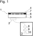
- a ceramic pressure transducer 1 is shown, on the ceramic base body 5, an acoustic sensor 2 is applied.
- the pressure transducer 1 serves in this embodiment of the capacitive pressure measurement in that the process pressure applied to the ceramic membrane 4 changes the distance between the measuring electrodes 6 and the counter electrode 7 and thus also influences the capacitances of the corresponding capacitors.
- the acoustic sensor 2 measures the structure-borne noise of the main body 5 and generates electrical (measuring) signals therefrom which are evaluated by the evaluation unit 3.
- the evaluation unit 3 comprises at least the following components: a bandpass filter 8, which in these embodiments only transmits frequencies within a band between 50 kHz and 3 MHz and filters out the noise signals in the process; an amplifier 9 which amplifies and conditions the filtered signals, and finally, for example, an analog-to-digital converter and a microprocessor which serves as the acoustic emission detector and, according to certain rules, detects the acoustic emission in the ceramic cell and, for example, operates an alarm output.
- a bandpass filter 8 which in these embodiments only transmits frequencies within a band between 50 kHz and 3 MHz and filters out the noise signals in the process
- an amplifier 9 which amplifies and conditions the filtered signals
- an analog-to-digital converter and a microprocessor which serves as the acoustic emission detector and, according to certain rules, detects the acoustic emission in the ceramic cell and, for example, operates an alarm output.
Landscapes
- Physics & Mathematics (AREA)
- Chemical & Material Sciences (AREA)
- Analytical Chemistry (AREA)
- General Physics & Mathematics (AREA)
- Acoustics & Sound (AREA)
- Health & Medical Sciences (AREA)
- Life Sciences & Earth Sciences (AREA)
- Biochemistry (AREA)
- General Health & Medical Sciences (AREA)
- Immunology (AREA)
- Pathology (AREA)
- Measuring Fluid Pressure (AREA)
Description
- Die Erfindung bezieht sich auf eine Vorrichtung zur Bestimmung und/oder Überwachung eines Drucks, mit mindestens einem Druckwandler, welcher den Druck in ein elektrisches Signal umwandelt. Weiterhin bezieht sich die Erfindung auf eine Vorrichtung zur Bestimmung und/oder Überwachung einer Prozessgröße, mit mindestens einer Sensoreinheit, welche die Prozessgröße bestimmt und/oder überwacht.
- Druckmessvorrichtungen werden vielfach in der Prozessmesstechnik eingesetzt, um den Druck von Prozessmedien zu messen, bei welchen es sich um Flüssigkeiten, Gase oder Dämpfe handeln kann. Im Wesentlichen umfassen derartige Messvorrichtungen oder Drucksensoren eine Druckmesszelle oder einen Druckwandler, welche im Allgemeinen einen Grundkörper und eine elastische Membran aufweist. Der Grundkörper und die Membran bestehen je nach Ausgestaltung aus einer Keramik oder zumindest die Membran besteht zumindest teilweise aus einem Metall. Mögliche Kombinationen von Membran und Grundkörper sind beispielsweise Keramik/Keramik, Metall/Keramik oder Metall/Metall mit dielektrischen Elementen bestehend aus der Keramik oder einem Glas. Das Lötverfahren von Metall auf Keramik ist bekannt und kann beispielsweise für eine Kombination Titan/Aluminiumoxidkeramik (oder Sonderlegierungen wie Kovar anstelle des Titan) realisiert werden. Es lässt sich beispielsweise auch eine dielektrische Keramik aus Aluminiumtitanat mit sehr geringem Ausdehnungskoeffizienten mit einer Nickellegierung Invar oder einer Siliziumkarbidkeramik im Lötverfahren kombinieren. Eine andere Ausgestaltung besteht in einer auf einen Edelstahlgrundkörper geschweißten Edelstahlmembran. Im Grundkörper wird vorzugsweise bei dieser Ausgestaltung ein Raum für ein Isolierelement mit den Messelektroden vorgesehen. Am Grundkörper ist zumeist eine flache Ausnehmung vorgesehen, welche auch als Membranbett bezeichnet und von der Membran überdeckt wird. Im Messbetrieb wird die Membran mit dem Druck des Prozessmediums beaufschlagt, und die Verformung oder die mechanische Spannung in der elastischen Membran, welche beispielsweise kapazitiv oder piezoresistiv ermittelt wird, ist ein Maß für den Druck (siehe z.B. die Offenlegungsschrift
DE 39 01 492 ). - Bei Keramikzellen solcher Drucktransmitter kann eine Rissbildung in der Membran Ursache für das Versagen der Zelle sein. Die Dicke solcher Membranen ist vom Messbereich des Drucks abhängig und liegt zumeist zwischen etwa 0,1 und 2 mm. Es ist bekannt, dass im Gegensatz zu Metallen keramische Werkstoffe aufgrund ihrer Sprödigkeit und der daraus resultierenden mangelnden plastischen Verformbarkeit sehr schnell brechen können, wenn die mechanische Spannung die Bruchgrenze erreicht. Die Ursache für einen Bruch der Membran können mikroskopische Risse in der Keramik sein, die unter Belastung ein überkritisches Wachstum erreicht haben. Bei manchen Fertigungsschritten, z.B. der Hartbearbeitung, können Risse induziert werden, welche jedoch aufgrund ihrer Größe nicht erkannt werden können. Eine weitere Ursache für kritisches Risswachstum kann eine lokale Überlast der Bauteile aufgrund einer ungünstigen Kombination des thermischen Gradienten während eines Temperaturschocks bei gleichzeitiger Druck- oder Vakuumbelastung sein. Die Messzellen können somit in Anwendungen mechanisch und thermisch überbelastet werden und reagieren darauf mit Risswachstum. Risse werden im Extremfall durch eine damit einhergehende Leckage erkannt, wodurch teilweise aufwendige Wartungsmaßnahmen erforderlich sind. Bei metallischen Membranen ist es weiterhin möglich, dass es durch Überdruck zu einer plastischen Verformung kommt, welche zu einer deutlichen Messabweichung führt. Im Stand der Technik ist beispielsweise für das Erkennen eines Membranbruchs die Verwendung einer Opfermembran vorgeschlagen, welche durch einen Korrosionsangriff oder andere kritische Ereignisse beschädigt wird. Der Ausfall der Opferzelle dient als ein Zeichen, dass die Messzelle auch beschädigt ist oder kurz vor der Beschädigung steht.
- Die Offenlegungsschrift
US 2007/0073417 A1 beschreibt einen Drucksensor, welcher mit einem akustischen Sensor gekoppelt ist, dessen Ausgangssignal mit dem des Drucksensors kombiniert wird. Der akustische Sensor misst den Druck einer Flüssigkeit an Hand der druckabhängigen Propagationszeit akustischer Signale in Flüssigkeiten. - Der Erfindung liegt die Aufgabe zugrunde, einen Drucktransmitter vorzuschlagen, bei welchem ein Bruch der Membran bzw. eine plastische Verformung erkannt wird. Die Aufgabe wird erfindungsgemäß durch die Vorrichtung gemäß Anspruch 1 gelöst.
- Die erfindungsgemäße Vorrichtung zur Bestimmung und Überwachung eines Drucks umfasst mindestens einen Druckwandler, welcher den Druck in ein elektrisches Signal umwandelt, wobei der Druckwandler mindestens eine Membran aufweist, welche mit dem Druck beaufschlagbar ist, wobei mindestens ein akustischer Sensor vorgesehen ist, welcher akustische Signale aufnimmt und in elektrische Signale umwandelt, wobei der akustische Sensor mechanisch und/oder akustisch mit dem Druckwandler gekoppelt ist, wobei mindestens eine Auswerteeinheit vorgesehen ist, welche die elektrischen Signale des akustischen Sensors in Hinsicht auf eine Brucherkennung oder auf eine plastische Verformung der Membran des Druckwandlers auswertet.
- Im erfindungsgemäßen Drucktransmitter wird somit ein bereits bekannter Drucksensor durch einen akustischen Sensor erweitert. Der Druckwandler besteht dabei zumindest teilweise aus einer Keramik und/oder aus einem Metall. Durch den zusätzlichen Sensor wird dabei eine akustische Diagnostik vorgenommen, welche sich entweder auf den Bruch oder auf die plastische Verformung bezieht. Es hat sich insbesondere gezeigt, dass keramische Werkstoffe, wie Aluminiumoxidkeramik oder Zirkonoxidkeramik kurz vor einem vollständigen Bruch einer Membran deutliche akustische Signale erzeugen. Solche Signale stammen aus mikroskopischen Brüchen in den Keramikkörnern und werden erfindungsgemäß mit einem akustischen Sensor aufgenommen. Die Frequenz der Signale liegt eventuell in einem Bereich zwischen 50 kHz und 3 MHz. In einer Ausgestaltung wird der akustische Sensor auf dem Grundkörper des Druckwandlers befestigt. Die eigentliche Befestigungsposition des akustischen Sensors ist unkritisch, da die akustischen Signale der genannten Frequenzen sich insbesondere in dem Fall eines keramischen Grundkörpers gut in einem solchen Keramikkörper ausbreiten.
- In der Anwendung ist die Membran dem zu messenden Prozessdruck bzw. dem Medium ausgesetzt. Die Membran besteht dabei insbesondere in einer Ausgestaltung aus einer Keramik. In einer weiteren Ausgestaltung besteht die Membran aus einem Metall.
- Eine Ausgestaltung sieht vor, dass die Auswerteeinheit die elektrischen Signale des akustischen Sensors in Hinsicht auf eine Brucherkennung der Membran des Druckwandlers auswertet. Diese Ausgestaltung bezieht sich insbesondere auf Keramikmembranen.
- Eine Ausgestaltung sieht vor, dass die Auswerteeinheit die elektrischen Signale des akustischen Sensors in Hinsicht auf eine plastische Verformung der Membran des Druckwandlers auswertet. Diese Ausgestaltung bezieht sich insbesondere auf Metallmembranen.
- Die Auswerteeinheit ist dabei in einer Ausgestaltung ein Bestandteil der Elektronik, mit welcher der Druckwandler verbunden ist. Die Auswerteeinheit kann jedoch auch eine übergeordnete Einheit, z.B. innerhalb einer Leitwarte sein. In einer Ausgestaltung werden die Signale und/oder deren Fouriertransformierte Spektren in Hinsicht auf die auftretenden Frequenzen und/oder Signalgruppen und/oder Einzelsignale ausgewertet.
- Eine Ausgestaltung beinhaltet, dass die Auswerteeinheit die elektrischen Signale des akustischen Sensors derartig auswertet, dass die Auswerteeinheit zumindest das Auftreten mindestens einer charakteristischen Frequenz und/oder mindestens einer charakteristischen Signalgruppe und/oder mindestens eines charakteristischen Einzelsignals in den elektrischen Signalen des akustischen Sensors erkennt und als Bruch oder plastische Verformung der Membran bewertet. Wie oben bereits ausgeführt, führen die Brüche in der Membran bzw. das plastische Verformen dieser zu besonderen Signalen, welche vom akustischen Sensor aufgenommen werden. Diese Signale innerhalb der elektronischen Signale des akustischen Sensors zeichnen sich beispielsweise durch charakteristische Frequenzen oder charakteristische Signalgruppen oder charakteristische Einzelsignale aus. Die elektronischen (Mess-)Signale des akustischen Sensors werden dabei beispielsweise durch eine Fourier-Transformation bzw. in Verbindung mit einem Bandpass-Filter ausgewertet. Somit ergibt sich beim Fall der Fourier-Transformation aus dem Signal des akustischen Sensors ein Spektrum, in welchem nach charakteristischen Signalen oder Frequenzen gesucht wird. Das Spektrum muss die kurzen Signale mit einer bestimmten Dauer einschließen. Die Mikrobrüche dauern nicht lang und diese Dauer entspricht den oben genannten Frequenzen von 50 kHz bis 3 MHz. Da zumeist die normalen Umgebungs-Rauschsignale in diesem Frequenzbereich sehr schwach sind, lassen sich dadurch die starken charakteristischen Signale erkennen und auswerten.
- Eine Ausgestaltung sieht vor, dass die Auswerteeinheit das zeitliche Verhalten der elektrischen Signale des akustischen Sensors auswertet. In dieser Ausgestaltung werden die Signale des akustischen Sensors in Hinsicht auf eine Vorhersage, also im Sinne der predictive maintenance ausgewertet, d.h. die einzelnen Signale des akustischen Sensors werden in Bezug auf zeitliche Entwicklungen oder Tendenzen ausgewertet. Dabei werden in einer Ausgestaltung die elektrischen Signale selbst ausgewertet und in einer weiteren Ausgestaltung werden die charakteristischen Einzelsignale oder Signalgruppen ausgewertet und in Bezug auf die zeitliche Entwicklung bewertet.
- Eine Ausgestaltung beinhaltet, dass der Druckwandler mindestens einen Grundkörper aufweist, dass die Membran mit einer Seite des Grundkörpers verbunden ist, und dass der akustische Sensor auf einer von der Membran abgewandten Seite des Grundkörpers aufgebracht ist.
- Eine Ausgestaltung sieht vor, dass es sich bei dem Druckwandler um einen kapazitiven Druckwandler handelt.
- Die Erfindung wird anhand der nachfolgenden Zeichnung näher erläutert. Es zeigt:
-
Fig. 1 : eine schematische Darstellung eines erfindungsgemäßen Druckmessgerätes. - In der
Fig. 1 ist schematisch ein keramischer Druckwandler 1 dargestellt, auf dessen keramischen Grundkörper 5 ein akustischer Sensor 2 aufgebracht ist. Der Druckwandler 1 dient dabei in dieser Ausgestaltung der kapazitiven Druckmessung, indem der auf der keramischen Membran 4 lastende Prozessdruck den Abstand zwischen den Messelektroden 6 und der Gegenelektrode 7 verändert und somit auch die Kapazitäten der entsprechenden Kondensatoren beeinflusst. - Der akustische Sensor 2 misst insbesondere den Körperschall des Grundkörpers 5 und erzeugt daraus elektrische (Mess-)Signale, welche von der Auswerteeinheit 3 ausgewertet werden.
- Die Auswerteeinheit 3 umfasst hier zumindest folgende Komponenten: ein Bandpass 8, welcher in dieser Ausgestaltungen nur Frequenzen innerhalb eines Bands zwischen 50 kHz und 3 MHz durchlässt und dabei die Rauschsignale herausfiltert; ein Verstärker 9, welcher die gefilterten Signale verstärkt und konditioniert, und schließlich beispielsweise ein Analog-DigitalWandler und ein Mikroprozessor, welcher als Detektor der akustischen Emission dient und nach bestimmten Regeln die akustische Emission in der keramischen Zelle erkennt und beispielsweise einen Alarmausgang bedient.
-
- 1
- Druckwandler
- 2
- Akustischer Sensor
- 3
- Auswerteeinheit
- 4
- Membran
- 5
- Grundkörper
- 6
- Messelektrode
- 7
- Gegenelektrode
- 8
- Bandpass
- 9
- Verstärker
- 10
- Mikroprozessor
Claims (5)
- Vorrichtung zur Bestimmung und/oder Überwachung eines Drucks, mit mindestens einem Druckwandler (1), welcher den Druck in ein elektrisches Signal umwandelt, wobei der Druckwandler (1) mindestens eine Membran (4) aufweist, welche mit dem Druck beaufschlagbar ist, wobei mindestens ein akustischer Sensor (2) vorgesehen ist, welcher akustische Signale aufnimmt und in elektrische Signale umwandelt, und welcher mechanisch und/oder akustisch mit dem Druckwandler (1) gekoppelt ist und wobei mindestens eine Auswerteeinheit (3) vorgesehen ist, wobei die Auswerteeinheit (3) die elektrischen Signale des akustischen Sensors (2) auswertet,
dadurch gekennzeichnet,
dass die Auswerteeinheit (3) die elektrischen Signale des akustischen Sensors (2) in Hinsicht auf eine Brucherkennung oder eine plastische Verformung der Membran (4) des Druckwandlers (1) auswertet. - Vorrichtung nach Anspruch 1,
dadurch gekennzeichnet,
dass die Auswerteeinheit (3) die elektrischen Signale des akustischen Sensors (2) derartig auswertet, dass die Auswerteeinheit (3) zumindest das Auftreten mindestens einer charakteristischen Frequenz und/oder mindestens einer charakteristischen Signalgruppe und/oder mindestens eines charakteristischen Einzelsignals in den elektrischen Signalen des akustischen Sensors (2) erkennt und als Bruch oder plastische Verformung der Membran (4) bewertet. - Vorrichtung nach Anspruch 1,
dadurch gekennzeichnet,
dass die Auswerteeinheit (3) das zeitliche Verhalten der elektrischen Signale des akustischen Sensors (2) auswertet. - Vorrichtung nach einem der Ansprüche 1 bis 3,
dadurch gekennzeichnet,
dass der Druckwandler (1) mindestens einen Grundkörper (5) aufweist, dass die Membran (4) mit einer Seite des Grundkörpers (5) verbunden ist, und
dass der akustische Sensor (2) auf einer von der Membran (4) abgewandten Seite des Grundkörpers (5) aufgebracht ist. - Vorrichtung nach einem der Ansprüche 1 bis 4,
dadurch gekennzeichnet,
dass es sich bei dem Druckwandler (1) um einen kapazitiven Druckwandler handelt.
Applications Claiming Priority (2)
| Application Number | Priority Date | Filing Date | Title |
|---|---|---|---|
| DE102008043467A DE102008043467A1 (de) | 2008-11-04 | 2008-11-04 | Vorrichtung zur Bestimmung und/oder Überwachung eines Drucks |
| PCT/EP2009/064129 WO2010052152A1 (de) | 2008-11-04 | 2009-10-27 | Vorrichtung zur bestimmung und/oder überwachung eines drucks |
Publications (2)
| Publication Number | Publication Date |
|---|---|
| EP2342546A1 EP2342546A1 (de) | 2011-07-13 |
| EP2342546B1 true EP2342546B1 (de) | 2018-12-12 |
Family
ID=41620137
Family Applications (1)
| Application Number | Title | Priority Date | Filing Date |
|---|---|---|---|
| EP09745016.7A Not-in-force EP2342546B1 (de) | 2008-11-04 | 2009-10-27 | Vorrichtung zur bestimmung und/oder überwachung eines drucks |
Country Status (4)
| Country | Link |
|---|---|
| US (1) | US8499641B2 (de) |
| EP (1) | EP2342546B1 (de) |
| DE (1) | DE102008043467A1 (de) |
| WO (1) | WO2010052152A1 (de) |
Families Citing this family (5)
| Publication number | Priority date | Publication date | Assignee | Title |
|---|---|---|---|---|
| DE102012112920A1 (de) | 2012-12-21 | 2014-06-26 | BD Sensors GmbH | Vorrichtung zur Bestimmung und/oder Überwachung eines Druckes |
| DE102014104506A1 (de) * | 2014-03-31 | 2015-10-01 | Endress + Hauser Gmbh + Co. Kg | Drucksensor |
| US11327050B2 (en) * | 2018-02-20 | 2022-05-10 | Intel Corporation | Mechanical failure monitoring, detection, and classification in electronic assemblies |
| DE102022133825A1 (de) * | 2022-12-19 | 2024-06-20 | Endress+Hauser SE+Co. KG | Druckmessaufnehmer |
| DE102023212474A1 (de) | 2023-12-11 | 2025-06-12 | Robert Bosch Gesellschaft mit beschränkter Haftung | Verfahren zur kombinierten Druck-Schall-Messung und Druck-Schall-Sensor |
Family Cites Families (11)
| Publication number | Priority date | Publication date | Assignee | Title |
|---|---|---|---|---|
| DE3901492A1 (de) | 1988-07-22 | 1990-01-25 | Endress Hauser Gmbh Co | Drucksensor und verfahren zu seiner herstellung |
| DE10103974B4 (de) * | 2001-01-30 | 2006-03-09 | Key Safety Systems, Inc., Sterling Heights | Vorrichtung zur Prüfung des Fülldruckes eines Airbag-Gasspeichers |
| DE10328296A1 (de) * | 2003-06-23 | 2005-01-20 | Endress + Hauser Gmbh + Co. Kg | Ansatzalarm bei Feldgeräten |
| DE10342368A1 (de) * | 2003-09-12 | 2005-04-28 | Siemens Ag | Druckmessumformer |
| DE102004033956A1 (de) * | 2004-07-14 | 2006-02-02 | Robert Bosch Gmbh | Sensoranordnung und Verfahren zur Funktionsüberprüfung von Sensoren mit Membran |
| DE102005009851A1 (de) * | 2005-03-03 | 2006-09-07 | Siemens Ag | Verfahren und Einrichtung zum Messen einer Kraft oder eines Druckes |
| DE102005015546A1 (de) * | 2005-04-04 | 2006-10-05 | Endress + Hauser Gmbh + Co. Kg | Vorrichtung zur Bestimmung und/oder Überwachung mindestens einer Prozessgröße |
| US7379792B2 (en) | 2005-09-29 | 2008-05-27 | Rosemount Inc. | Pressure transmitter with acoustic pressure sensor |
| DE102005055285A1 (de) * | 2005-11-17 | 2007-05-24 | Endress + Hauser Gmbh + Co. Kg | Druckmessumformer mit Diagnosefunktion |
| DE102007016792B4 (de) * | 2007-04-05 | 2013-05-29 | Ifm Electronic Gmbh | Sensor |
| DE102007046016A1 (de) * | 2007-09-26 | 2009-04-02 | Robert Bosch Gmbh | Gasdrucksensor für ein Kraftfahrzeug und Verfahren zur Prüfung eines Gasdrucksensors für ein Kraftfahrzeug |
-
2008
- 2008-11-04 DE DE102008043467A patent/DE102008043467A1/de not_active Withdrawn
-
2009
- 2009-10-27 EP EP09745016.7A patent/EP2342546B1/de not_active Not-in-force
- 2009-10-27 WO PCT/EP2009/064129 patent/WO2010052152A1/de not_active Ceased
- 2009-10-27 US US13/127,510 patent/US8499641B2/en not_active Expired - Fee Related
Non-Patent Citations (1)
| Title |
|---|
| None * |
Also Published As
| Publication number | Publication date |
|---|---|
| US20110265573A1 (en) | 2011-11-03 |
| EP2342546A1 (de) | 2011-07-13 |
| DE102008043467A1 (de) | 2010-05-06 |
| WO2010052152A1 (de) | 2010-05-14 |
| US8499641B2 (en) | 2013-08-06 |
Similar Documents
| Publication | Publication Date | Title |
|---|---|---|
| EP0759547B1 (de) | Drucksensor | |
| EP2342546A1 (de) | Vorrichtung zur bestimmung und/oder überwachung eines drucks | |
| WO2014195076A2 (de) | Messgerät | |
| WO2007124924A2 (de) | Verbindungsbauteil mit temperaturfestem sensorelement | |
| DE102012102589A1 (de) | Vorrichtung zur Überwachung eines vorbestimmten Füllstands | |
| EP3421950B1 (de) | Durchflusssensor, verfahren und durchflussmessgerät zur bestimmung von geschwindigkeiten von phasen eines mehrphasigen mediums | |
| DE102008043764A1 (de) | Vorrichtung zur Bestimmung und/oder Überwachung einer Prozessgröße | |
| EP1275951B1 (de) | Drucksensor und Verfahren zu dessen Betriebsüberwachung | |
| WO2007023168A1 (de) | Drucksensor für hydraulische medien in kraftfahrzeugbremssystemen und dessen verwendung | |
| DE102018131948B4 (de) | Verfahren und Vorrichtung zum Detektieren eines Schlagereignisses sowie ein Fahrzeug hierzu | |
| WO2015007267A2 (de) | System zum messen einer axialkraft einer schraubverbindung | |
| EP3767266B1 (de) | Druckmittlersystem oder druckmessumformer mit integriertem selbsttest | |
| DE102018108743A1 (de) | Drucksensor | |
| DE102018209877A1 (de) | Elektrochemische Energiespeichervorrichtung, System und Verfahren zur Überwachung einer elektrochemischen Energiespeichervorrichtung sowie Fahrzeug | |
| DE102006004941A1 (de) | Verfahren und Einrichtung zur Detektion des Ortes einer impulsartigen mechanischen Einwirkung auf ein Anlagenteil | |
| EP2110649A1 (de) | Sensor für die Zustandsüberwachung von mechanischen Bauteilen | |
| DE558690C (de) | Einrichtung zum Messen oder Registrieren von Druckaenderungen mit Hilfe eines Kondensators | |
| DE102006058269B4 (de) | Verfahren zur Kalibrierung mindestens eines Drucksensors und entsprechender Drucksensor | |
| EP2541541B1 (de) | Anordnung zur zerstörungsfreien Überwachung oder Prüfung von Bauteilen mittels Schallwellenanalyse | |
| EP3450593B1 (de) | Verfahren und sensoreinrichtung zur störungskompensierten bestimmung des materialauftrags oder -abtrags während nasschemischer prozesse | |
| DE102023102928B4 (de) | Verfahren zur Kompensation eines Temperaturschocks an einer kapazitiven Druckmesszelle | |
| DE102023107963B3 (de) | Verfahren zur Kompensation eines Temperaturschocks an einer kapazitiven Druckmesszelle | |
| WO2020177953A1 (de) | Drucksensoranordnung | |
| DE102021118886B3 (de) | Druckmittler mit Test-Klebeschicht und Verfahren zum Überwachen eines Druckmittlers | |
| DE102020116702A1 (de) | Druckmessgerät |
Legal Events
| Date | Code | Title | Description |
|---|---|---|---|
| PUAI | Public reference made under article 153(3) epc to a published international application that has entered the european phase |
Free format text: ORIGINAL CODE: 0009012 |
|
| 17P | Request for examination filed |
Effective date: 20110414 |
|
| AK | Designated contracting states |
Kind code of ref document: A1 Designated state(s): AT BE BG CH CY CZ DE DK EE ES FI FR GB GR HR HU IE IS IT LI LT LU LV MC MK MT NL NO PL PT RO SE SI SK SM TR |
|
| AX | Request for extension of the european patent |
Extension state: AL BA RS |
|
| RAP1 | Party data changed (applicant data changed or rights of an application transferred) |
Owner name: ENDRESS+HAUSER GMBH+CO. KG |
|
| DAX | Request for extension of the european patent (deleted) | ||
| STAA | Information on the status of an ep patent application or granted ep patent |
Free format text: STATUS: EXAMINATION IS IN PROGRESS |
|
| 17Q | First examination report despatched |
Effective date: 20170622 |
|
| RAP1 | Party data changed (applicant data changed or rights of an application transferred) |
Owner name: ENDRESS+HAUSER SE+CO. KG |
|
| GRAP | Despatch of communication of intention to grant a patent |
Free format text: ORIGINAL CODE: EPIDOSNIGR1 |
|
| STAA | Information on the status of an ep patent application or granted ep patent |
Free format text: STATUS: GRANT OF PATENT IS INTENDED |
|
| INTG | Intention to grant announced |
Effective date: 20180727 |
|
| GRAS | Grant fee paid |
Free format text: ORIGINAL CODE: EPIDOSNIGR3 |
|
| GRAA | (expected) grant |
Free format text: ORIGINAL CODE: 0009210 |
|
| STAA | Information on the status of an ep patent application or granted ep patent |
Free format text: STATUS: THE PATENT HAS BEEN GRANTED |
|
| AK | Designated contracting states |
Kind code of ref document: B1 Designated state(s): AT BE BG CH CY CZ DE DK EE ES FI FR GB GR HR HU IE IS IT LI LT LU LV MC MK MT NL NO PL PT RO SE SI SK SM TR |
|
| REG | Reference to a national code |
Ref country code: GB Ref legal event code: FG4D Free format text: NOT ENGLISH |
|
| REG | Reference to a national code |
Ref country code: CH Ref legal event code: EP |
|
| REG | Reference to a national code |
Ref country code: AT Ref legal event code: REF Ref document number: 1076654 Country of ref document: AT Kind code of ref document: T Effective date: 20181215 |
|
| REG | Reference to a national code |
Ref country code: DE Ref legal event code: R096 Ref document number: 502009015508 Country of ref document: DE |
|
| REG | Reference to a national code |
Ref country code: IE Ref legal event code: FG4D Free format text: LANGUAGE OF EP DOCUMENT: GERMAN |
|
| REG | Reference to a national code |
Ref country code: NL Ref legal event code: MP Effective date: 20181212 |
|
| REG | Reference to a national code |
Ref country code: LT Ref legal event code: MG4D |
|
| PG25 | Lapsed in a contracting state [announced via postgrant information from national office to epo] |
Ref country code: NO Free format text: LAPSE BECAUSE OF FAILURE TO SUBMIT A TRANSLATION OF THE DESCRIPTION OR TO PAY THE FEE WITHIN THE PRESCRIBED TIME-LIMIT Effective date: 20190312 Ref country code: HR Free format text: LAPSE BECAUSE OF FAILURE TO SUBMIT A TRANSLATION OF THE DESCRIPTION OR TO PAY THE FEE WITHIN THE PRESCRIBED TIME-LIMIT Effective date: 20181212 Ref country code: LT Free format text: LAPSE BECAUSE OF FAILURE TO SUBMIT A TRANSLATION OF THE DESCRIPTION OR TO PAY THE FEE WITHIN THE PRESCRIBED TIME-LIMIT Effective date: 20181212 Ref country code: BG Free format text: LAPSE BECAUSE OF FAILURE TO SUBMIT A TRANSLATION OF THE DESCRIPTION OR TO PAY THE FEE WITHIN THE PRESCRIBED TIME-LIMIT Effective date: 20190312 Ref country code: ES Free format text: LAPSE BECAUSE OF FAILURE TO SUBMIT A TRANSLATION OF THE DESCRIPTION OR TO PAY THE FEE WITHIN THE PRESCRIBED TIME-LIMIT Effective date: 20181212 Ref country code: FI Free format text: LAPSE BECAUSE OF FAILURE TO SUBMIT A TRANSLATION OF THE DESCRIPTION OR TO PAY THE FEE WITHIN THE PRESCRIBED TIME-LIMIT Effective date: 20181212 Ref country code: LV Free format text: LAPSE BECAUSE OF FAILURE TO SUBMIT A TRANSLATION OF THE DESCRIPTION OR TO PAY THE FEE WITHIN THE PRESCRIBED TIME-LIMIT Effective date: 20181212 |
|
| PG25 | Lapsed in a contracting state [announced via postgrant information from national office to epo] |
Ref country code: SE Free format text: LAPSE BECAUSE OF FAILURE TO SUBMIT A TRANSLATION OF THE DESCRIPTION OR TO PAY THE FEE WITHIN THE PRESCRIBED TIME-LIMIT Effective date: 20181212 Ref country code: GR Free format text: LAPSE BECAUSE OF FAILURE TO SUBMIT A TRANSLATION OF THE DESCRIPTION OR TO PAY THE FEE WITHIN THE PRESCRIBED TIME-LIMIT Effective date: 20190313 |
|
| PG25 | Lapsed in a contracting state [announced via postgrant information from national office to epo] |
Ref country code: NL Free format text: LAPSE BECAUSE OF FAILURE TO SUBMIT A TRANSLATION OF THE DESCRIPTION OR TO PAY THE FEE WITHIN THE PRESCRIBED TIME-LIMIT Effective date: 20181212 |
|
| PG25 | Lapsed in a contracting state [announced via postgrant information from national office to epo] |
Ref country code: PL Free format text: LAPSE BECAUSE OF FAILURE TO SUBMIT A TRANSLATION OF THE DESCRIPTION OR TO PAY THE FEE WITHIN THE PRESCRIBED TIME-LIMIT Effective date: 20181212 Ref country code: IT Free format text: LAPSE BECAUSE OF FAILURE TO SUBMIT A TRANSLATION OF THE DESCRIPTION OR TO PAY THE FEE WITHIN THE PRESCRIBED TIME-LIMIT Effective date: 20181212 Ref country code: CZ Free format text: LAPSE BECAUSE OF FAILURE TO SUBMIT A TRANSLATION OF THE DESCRIPTION OR TO PAY THE FEE WITHIN THE PRESCRIBED TIME-LIMIT Effective date: 20181212 Ref country code: PT Free format text: LAPSE BECAUSE OF FAILURE TO SUBMIT A TRANSLATION OF THE DESCRIPTION OR TO PAY THE FEE WITHIN THE PRESCRIBED TIME-LIMIT Effective date: 20190412 |
|
| PG25 | Lapsed in a contracting state [announced via postgrant information from national office to epo] |
Ref country code: RO Free format text: LAPSE BECAUSE OF FAILURE TO SUBMIT A TRANSLATION OF THE DESCRIPTION OR TO PAY THE FEE WITHIN THE PRESCRIBED TIME-LIMIT Effective date: 20181212 Ref country code: IS Free format text: LAPSE BECAUSE OF FAILURE TO SUBMIT A TRANSLATION OF THE DESCRIPTION OR TO PAY THE FEE WITHIN THE PRESCRIBED TIME-LIMIT Effective date: 20190412 Ref country code: EE Free format text: LAPSE BECAUSE OF FAILURE TO SUBMIT A TRANSLATION OF THE DESCRIPTION OR TO PAY THE FEE WITHIN THE PRESCRIBED TIME-LIMIT Effective date: 20181212 Ref country code: SM Free format text: LAPSE BECAUSE OF FAILURE TO SUBMIT A TRANSLATION OF THE DESCRIPTION OR TO PAY THE FEE WITHIN THE PRESCRIBED TIME-LIMIT Effective date: 20181212 Ref country code: SK Free format text: LAPSE BECAUSE OF FAILURE TO SUBMIT A TRANSLATION OF THE DESCRIPTION OR TO PAY THE FEE WITHIN THE PRESCRIBED TIME-LIMIT Effective date: 20181212 |
|
| REG | Reference to a national code |
Ref country code: DE Ref legal event code: R097 Ref document number: 502009015508 Country of ref document: DE |
|
| PLBE | No opposition filed within time limit |
Free format text: ORIGINAL CODE: 0009261 |
|
| STAA | Information on the status of an ep patent application or granted ep patent |
Free format text: STATUS: NO OPPOSITION FILED WITHIN TIME LIMIT |
|
| PG25 | Lapsed in a contracting state [announced via postgrant information from national office to epo] |
Ref country code: DK Free format text: LAPSE BECAUSE OF FAILURE TO SUBMIT A TRANSLATION OF THE DESCRIPTION OR TO PAY THE FEE WITHIN THE PRESCRIBED TIME-LIMIT Effective date: 20181212 Ref country code: SI Free format text: LAPSE BECAUSE OF FAILURE TO SUBMIT A TRANSLATION OF THE DESCRIPTION OR TO PAY THE FEE WITHIN THE PRESCRIBED TIME-LIMIT Effective date: 20181212 |
|
| 26N | No opposition filed |
Effective date: 20190913 |
|
| PGFP | Annual fee paid to national office [announced via postgrant information from national office to epo] |
Ref country code: DE Payment date: 20191021 Year of fee payment: 11 |
|
| PG25 | Lapsed in a contracting state [announced via postgrant information from national office to epo] |
Ref country code: TR Free format text: LAPSE BECAUSE OF FAILURE TO SUBMIT A TRANSLATION OF THE DESCRIPTION OR TO PAY THE FEE WITHIN THE PRESCRIBED TIME-LIMIT Effective date: 20181212 |
|
| PG25 | Lapsed in a contracting state [announced via postgrant information from national office to epo] |
Ref country code: MC Free format text: LAPSE BECAUSE OF FAILURE TO SUBMIT A TRANSLATION OF THE DESCRIPTION OR TO PAY THE FEE WITHIN THE PRESCRIBED TIME-LIMIT Effective date: 20181212 |
|
| REG | Reference to a national code |
Ref country code: CH Ref legal event code: PL |
|
| PG25 | Lapsed in a contracting state [announced via postgrant information from national office to epo] |
Ref country code: LI Free format text: LAPSE BECAUSE OF NON-PAYMENT OF DUE FEES Effective date: 20191031 Ref country code: LU Free format text: LAPSE BECAUSE OF NON-PAYMENT OF DUE FEES Effective date: 20191027 Ref country code: CH Free format text: LAPSE BECAUSE OF NON-PAYMENT OF DUE FEES Effective date: 20191031 |
|
| REG | Reference to a national code |
Ref country code: BE Ref legal event code: MM Effective date: 20191031 |
|
| PG25 | Lapsed in a contracting state [announced via postgrant information from national office to epo] |
Ref country code: BE Free format text: LAPSE BECAUSE OF NON-PAYMENT OF DUE FEES Effective date: 20191031 |
|
| GBPC | Gb: european patent ceased through non-payment of renewal fee |
Effective date: 20191027 |
|
| PG25 | Lapsed in a contracting state [announced via postgrant information from national office to epo] |
Ref country code: IE Free format text: LAPSE BECAUSE OF NON-PAYMENT OF DUE FEES Effective date: 20191027 Ref country code: FR Free format text: LAPSE BECAUSE OF NON-PAYMENT OF DUE FEES Effective date: 20191031 Ref country code: GB Free format text: LAPSE BECAUSE OF NON-PAYMENT OF DUE FEES Effective date: 20191027 |
|
| REG | Reference to a national code |
Ref country code: AT Ref legal event code: MM01 Ref document number: 1076654 Country of ref document: AT Kind code of ref document: T Effective date: 20191027 |
|
| PG25 | Lapsed in a contracting state [announced via postgrant information from national office to epo] |
Ref country code: AT Free format text: LAPSE BECAUSE OF NON-PAYMENT OF DUE FEES Effective date: 20191027 |
|
| REG | Reference to a national code |
Ref country code: DE Ref legal event code: R119 Ref document number: 502009015508 Country of ref document: DE |
|
| PG25 | Lapsed in a contracting state [announced via postgrant information from national office to epo] |
Ref country code: CY Free format text: LAPSE BECAUSE OF FAILURE TO SUBMIT A TRANSLATION OF THE DESCRIPTION OR TO PAY THE FEE WITHIN THE PRESCRIBED TIME-LIMIT Effective date: 20181212 |
|
| PG25 | Lapsed in a contracting state [announced via postgrant information from national office to epo] |
Ref country code: DE Free format text: LAPSE BECAUSE OF NON-PAYMENT OF DUE FEES Effective date: 20210501 Ref country code: HU Free format text: LAPSE BECAUSE OF FAILURE TO SUBMIT A TRANSLATION OF THE DESCRIPTION OR TO PAY THE FEE WITHIN THE PRESCRIBED TIME-LIMIT; INVALID AB INITIO Effective date: 20091027 Ref country code: MT Free format text: LAPSE BECAUSE OF FAILURE TO SUBMIT A TRANSLATION OF THE DESCRIPTION OR TO PAY THE FEE WITHIN THE PRESCRIBED TIME-LIMIT Effective date: 20181212 |
|
| PG25 | Lapsed in a contracting state [announced via postgrant information from national office to epo] |
Ref country code: MK Free format text: LAPSE BECAUSE OF FAILURE TO SUBMIT A TRANSLATION OF THE DESCRIPTION OR TO PAY THE FEE WITHIN THE PRESCRIBED TIME-LIMIT Effective date: 20181212 |