EP2341226A1 - Engine generator - Google Patents
Engine generator Download PDFInfo
- Publication number
- EP2341226A1 EP2341226A1 EP09823590A EP09823590A EP2341226A1 EP 2341226 A1 EP2341226 A1 EP 2341226A1 EP 09823590 A EP09823590 A EP 09823590A EP 09823590 A EP09823590 A EP 09823590A EP 2341226 A1 EP2341226 A1 EP 2341226A1
- Authority
- EP
- European Patent Office
- Prior art keywords
- cooling air
- engine
- housing
- disposed
- air inlet
- Prior art date
- Legal status (The legal status is an assumption and is not a legal conclusion. Google has not performed a legal analysis and makes no representation as to the accuracy of the status listed.)
- Withdrawn
Links
Images




Classifications
-
- F—MECHANICAL ENGINEERING; LIGHTING; HEATING; WEAPONS; BLASTING
- F02—COMBUSTION ENGINES; HOT-GAS OR COMBUSTION-PRODUCT ENGINE PLANTS
- F02B—INTERNAL-COMBUSTION PISTON ENGINES; COMBUSTION ENGINES IN GENERAL
- F02B63/00—Adaptations of engines for driving pumps, hand-held tools or electric generators; Portable combinations of engines with engine-driven devices
- F02B63/04—Adaptations of engines for driving pumps, hand-held tools or electric generators; Portable combinations of engines with engine-driven devices for electric generators
-
- F—MECHANICAL ENGINEERING; LIGHTING; HEATING; WEAPONS; BLASTING
- F01—MACHINES OR ENGINES IN GENERAL; ENGINE PLANTS IN GENERAL; STEAM ENGINES
- F01P—COOLING OF MACHINES OR ENGINES IN GENERAL; COOLING OF INTERNAL-COMBUSTION ENGINES
- F01P1/00—Air cooling
- F01P1/06—Arrangements for cooling other engine or machine parts
-
- F—MECHANICAL ENGINEERING; LIGHTING; HEATING; WEAPONS; BLASTING
- F01—MACHINES OR ENGINES IN GENERAL; ENGINE PLANTS IN GENERAL; STEAM ENGINES
- F01P—COOLING OF MACHINES OR ENGINES IN GENERAL; COOLING OF INTERNAL-COMBUSTION ENGINES
- F01P1/00—Air cooling
- F01P2001/005—Cooling engine rooms
-
- F—MECHANICAL ENGINEERING; LIGHTING; HEATING; WEAPONS; BLASTING
- F01—MACHINES OR ENGINES IN GENERAL; ENGINE PLANTS IN GENERAL; STEAM ENGINES
- F01P—COOLING OF MACHINES OR ENGINES IN GENERAL; COOLING OF INTERNAL-COMBUSTION ENGINES
- F01P2050/00—Applications
- F01P2050/30—Circuit boards
-
- F—MECHANICAL ENGINEERING; LIGHTING; HEATING; WEAPONS; BLASTING
- F01—MACHINES OR ENGINES IN GENERAL; ENGINE PLANTS IN GENERAL; STEAM ENGINES
- F01P—COOLING OF MACHINES OR ENGINES IN GENERAL; COOLING OF INTERNAL-COMBUSTION ENGINES
- F01P3/00—Liquid cooling
- F01P3/20—Cooling circuits not specific to a single part of engine or machine
-
- F—MECHANICAL ENGINEERING; LIGHTING; HEATING; WEAPONS; BLASTING
- F02—COMBUSTION ENGINES; HOT-GAS OR COMBUSTION-PRODUCT ENGINE PLANTS
- F02B—INTERNAL-COMBUSTION PISTON ENGINES; COMBUSTION ENGINES IN GENERAL
- F02B63/00—Adaptations of engines for driving pumps, hand-held tools or electric generators; Portable combinations of engines with engine-driven devices
- F02B63/04—Adaptations of engines for driving pumps, hand-held tools or electric generators; Portable combinations of engines with engine-driven devices for electric generators
- F02B63/044—Adaptations of engines for driving pumps, hand-held tools or electric generators; Portable combinations of engines with engine-driven devices for electric generators the engine-generator unit being placed on a frame or in an housing
Definitions
- the present invention relates to engine generators including engines and generators driven by the engines, and particularly to an internal structure of an engine generator for enhancing the efficiency of cooling an inverter and an air cleaner to which cooling needs to be effected.
- engine generators accommodate adjacent engines and generators within housings (packages) (see, for example, patent document 1).
- the engine generators each include an inverter to rectify electrical power generated by the generator and convert the rectified electrical power into a desired frequency.
- the housing accommodates the engine, the generator, the inverter, and all of other necessary components. Attempts to bring simplicity and compactness to the structure of the necessary components have resulted in ease of handling of the engine generator during installation, transfer, and maintenance.
- the inverter which is an electrical component vulnerable to heat, is located approximately at the center inside the housing together with the heat source engine and generator. This provides a possibility of increasing the temperature of the inverter due to heat generated by the heat sources, as well as heat generated by the inverter itself. This may lead electrical circuits into problematic situations including changes in voltage and frequency.
- an engine generator includes an engine, a generator, at least one inverter, a control device, a fuel tank, an air cleaner, a muffler, a radiator, and a housing.
- the generator is driven by the engine to generate electrical power.
- the at least one inverter is configured to convert the electrical power generated by the generator into an alternating current and to output the alternating current.
- the control device is configured to control the engine and the generator.
- the fuel tank is to store fuel to be supplied to the engine.
- the air cleaner is configured to purify air to be supplied to the engine.
- the muffler is configured to deaden exhaust noise of the engine.
- the radiator is configured to cool coolant for the engine.
- the housing accommodates the foregoing components.
- At least one cooling air inlet is disposed on a first side of the housing corresponding to a first side of the engine.
- a cooling air outlet is disposed on a second side of the housing corresponding to a second side of the engine.
- a cooling air passage is disposed in the housing between the at least one cooling air inlet and the cooling air outlet.
- the generator, the inverter, and the air cleaner are disposed further upstream than the engine along the cooling air passage.
- the fuel tank, the radiator, and the muffler are disposed further downstream than the engine along the cooling air passage.
- ambient air is incorporated as cooling air into the housing through the at least one cooling air inlet, allowed to flow from an upstream toward a downstream of the cooling air passage, and discharged to outside the housing through the cooling air outlet.
- the at least one cooling air inlet may include upper and lower first cooling air inlets respectively on upper and lower portions of the first side of the housing.
- the at least one inverter may include two, upper and lower inverters in the housing and in parallel to the first side of the housing.
- the upper and lower inverters may be respectively opposite the upper and lower first cooling air inlets.
- a support may be disposed between and in parallel to the upper and lower inverters and the first side of the housing.
- the support may include a first duct constituting the cooling air passage.
- the first duct may extend from the upper and lower first cooling air inlets toward the upper and lower inverters.
- the cooling air may be allowed to flow through the at least one cooling air inlet into the first duct and may be guided upward and downward along the upper and lower inverters.
- the engine generator of according to the foregoing aspect of the present invention may further include a partition in the first duct to vertically split the cooling air from the upper and lower first cooling air inlets. Part of the cooling air flowing into the first duct may be guided upward along the upper inverter. A rest of the cooling air flowing into the first duct may be guided downward along the lower inverter.
- the at least one cooling air inlet may include a second cooling air inlet at a lower portion of a third side of the housing.
- a guiding member in box form may be disposed in the housing in parallel to the lower portion of the third side of the housing and opposite the second cooling air inlet.
- the guiding member may have an opening oriented upward and toward the second cooling air inlet.
- the guiding member may include a second duct constituting the cooling air passage.
- the second duct may extend from the second cooling air inlet to an upper portion of an interior of the housing.
- the second cooling air inlet and the second duct may communicate with one another to allow cooling air from the second cooling air inlet to flow into the second duct and be guided upward along the guiding member.
- the radiator may be disposed in parallel to the fuel tank with a longitudinal side of the radiator oriented in a lateral direction and aligned to a longitudinal side of the fuel tank.
- the engine generator ensures cooling of the inverter and the air cleaner, which particularly need cooling, with cooling air of a relatively low temperature. This ensures efficient cooling of the components as necessary, resulting in an improved cooling effect realized by cooling air. Further, the other components are disposed as if to surround the engine. This ensures a compact arrangement of the other components, while reducing noise of the engine with the other components utilized as sound barriers.
- the engine generator according to an embodiment of the present invention also ensures that cooling air is sent toward the upper and lower inverters through the first duct. This ensures efficient cooling of the upper and lower inverters with the cooling air, resulting in an improved cooling effect realized by cooling air.
- the first duct is disposed on the inside relative to the first cooling air inlet. This reduces leakage of noise to outside the housing through the first cooling air inlet.
- the engine generator according to an embodiment of the present invention also ensures that cooling air is vertically split into upper and lower inverters and that equal volumes of cooling air are sent toward the upper and lower inverters. This uniformizes cooling of the upper and lower inverters with the cooling air and thus reduces unevenness of the cooling effect utilizing cooling air.
- the second duct is disposed on the inside relative to the second cooling air inlet. This reduces leakage of noise to outside the housing through the second cooling air inlet.
- the engine generator according to an embodiment of the present invention also ensures as much cooling capacity of the radiator as desired and increases the capacity of the fuel tank, while ensuring a compact arrangement of the radiator and the fuel tank in the housing.
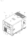
- FIG. 1 is a perspective view of a housing of an engine generator, illustrating an external configuration of the housing
- FIG. 2 is a perspective view of the housing of the engine generator, illustrating an internal configuration of the housing
- FIG. 3 is a side view of a right side of the housing, illustrating a partial configuration of the right side
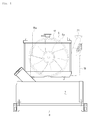
- FIG. 4 is a rear view of the housing, illustrating a rear side configuration of the interior of the housing
- FIG. 5 is a side view of the housing, illustrating a configuration around a forward portion of the right side of the housing
- FIG. 6 is a front cross-sectional view, illustrating a configuration around the forward portion of the right side of the housing
- FIG. 7 is a perspective view of the housing, illustrating a configuration around a forward portion of the right side of the housing
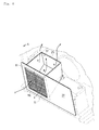
- FIG. 8 is a perspective view of the housing, illustrating a configuration around a front side of the housing.
- the engine generator 1 is an engine generator of an inverter type.
- the engine generator 1 includes a housing 5, an engine 2, a generator 3, an inverter 4, a cooling fan 17, a radiator 6, a fuel tank 7, an air cleaner 16, a muffler 18, a control device, and a battery 24.
- the housing 5 which is a package of the engine generator 1, accommodates the components such as the engine 2 and the generator 3.
- the housing 5 includes a base 8 at bottom and a cover 9 on top.
- the engine 2 serves as a driving source for the components in the housing 5.
- the engine 2 is disposed approximately at the center on the interior of the housing 5, and supported on the upper surface of the base 8 through an antivibration member, not shown.
- the generator 3 is powered by the engine 2 to generate electrical power.
- the generator 3 is disposed further forward than the engine 2 and further rearward than the battery 24.
- the inverter 4 rectifies the electrical power generated by the generator 3 and then converts the rectified electrical power into alternate-current electrical power of a predetermined frequency to output the alternate-current electrical power.
- the inverter 4 is disposed in the right-forward direction relative to the engine 2 and disposed on the right side of the housing 5, that is, adjacent to a forward portion of a right plate 9b of the cover 9.
- the cooling fan 17 incorporates ambient air into the housing 5.
- the cooling fan 17 is disposed in the housing 5 further rearward than the engine 2 and further forward than the radiator 6, and is powered by the engine 2.
- the radiator 6 cools coolant to be circulated within the engine 2.
- the radiator 6 is disposed in the housing 5 further rearward than the cooling fan 17 and further upward than the fuel tank 7, and is coupled to the engine 2 through communication pipes 19 and 20.
- the fuel tank 7 stores fuel to be supplied to the engine 2.
- the fuel tank 7 is disposed approximately further rearward than the engine 2 and further downward than the radiator 6.
- the air cleaner 16 purifies ambient air and supplies the purified ambient air to the engine 2.
- the air cleaner 16 is disposed approximately in the left-forward direction relative to the engine and further upward than the battery 24, and is coupled to the engine 2 through an inlet pipe 22.
- the muffler 18 deadens exhaust noise of the engine 2.
- the muffler 18 is disposed further rearward than the radiator 6 and further upward than the fuel tank 7, and is coupled to the engine 2 through a discharge pipe 21.
- the muffler 18 extends a tail pipe 18a upward adjacent to the ceiling of the housing, that is, adjacent to a ceiling plate 9d of the cover, with the tail pipe 18a communicating with ambient at an extension end. This ensures that discharge gas of the engine 2 is discharged to outside the housing 5 through the tail pipe 18a by way of the discharge pipe 21 and the muffler 18.
- the control device controls the engine 2 and the generator 3.
- the control device is disposed further forward than the generator 3 and further upward than the battery 24, and disposed adjacent to the front side of the housing 5, that is, adjacent to a forward portion of a front plate 9a of the cover 9.
- a control panel 10 is used to operate the engine generator 1 such as for start-up and to display driving conditions and other conditions.
- the control panel 10 is disposed further forward than the control device, and exposed to ambient at the front side of the housing 5, that is, at an upper portion of the front plate 9a of the cover 9.
- the control panel 10 includes switches and similar devices to operate driving of the engine generator 1 and a monitor or a similar device to display driving conditions of the engine generator 1.
- the battery 24, at the start-up of the engine 2, supplies electrical power to a starter, not shown, to a controller of the inverter 4, to the control panel 10, described later, and to other components.
- the battery 24 is disposed on a forward portion of the base 8.
- the housing 5 accommodates the components of the engine generator 1.
- the engine 2 starts when fueled by the fuel tank 7 and supplied with air through the air cleaner 16.
- the power of the engine 2 drives the generator 3 to generate electrical power.
- the inverter 4 rectifies the electrical power generated by the generator 3, then converts the rectified electrical power into alternate-current electrical power of a predetermined frequency, and outputs the alternate-current electrical power.
- the housing 5 includes the base 8 and the cover 9, as described above.
- the base 8 is disposed at the bottom of the housing 5 and is rectangular in plan view.
- the cover 9 is disposed at the top of the housing 5 in the form of a cubic box having an opening oriented downward, and covered by the base 8 from the downward direction.
- a second cooling air inlet 11 is disposed on the front side of the housing 5, that is, on the front plate 9a of the cover 9.
- the second cooling air inlet 11 includes a group of openings 11a and is disposed at a lower right portion of the front plate 9a.
- the second cooling air inlet 11 provides communication between ambient and the interior of the housing 5. This ensures that upon driving of the cooling fan 17 by the engine 2, ambient air is incorporated into the housing 5 as cooling air.
- Upper and lower first cooling air inlets 12 are disposed on the right side of the housing 5, that is, on a right plate of the cover 9.
- the upper first cooling air inlet 12A includes a group of openings 12a and is disposed at an upper forward portion of the right plate.
- the lower first cooling air inlet 12B includes a group of openings 12b and is disposed at a lower forward portion of the right plate, that is, further downward than the upper first cooling air inlet 12A.
- the first cooling air inlets 12 provide communication between ambient and the interior of the housing 5. This ensures that upon driving of the cooling fan 17 by the engine 2, ambient air is incorporated into the housing 5 as cooling air.
- a cooling air outlet 14 is disposed on the ceiling (top side) of the housing 5, that is, on a ceiling plate 9d of the cover 9.
- the cooling air outlet 14 includes a group of openings 14a and is disposed at a rearward portion of the ceiling plate 9d.
- the cooling air outlet 14 provides communication between the interior of the housing 5 and ambient. This ensures that upon driving of the cooling fan 17 by the engine 2, cooling air incorporated in the housing 5 is discharged to outside the housing 5.
- a cooling air passage is defined between the upper and lower first cooling air inlets 12A and 12B and the cooling air outlet 14 to extend in the forward/rearward directions.
- another cooling air passage is defined between the second cooling air inlet 11 and the cooling air outlet 14 to extend in the forward/rearward directions.
- the engine 2 is disposed along the length of the cooling air passages.
- the engine 2 is disposed approximately at the center inside the housing 5, with the axial direction of the crank shaft assumed the forward/rearward direction.
- the space further forward than the engine 2 is defined as the upstream of each cooling air passage, while the space further rearward than the engine 2 is defined as the downstream of each cooling air passage.
- the generator 3, the inverter 4, and the air cleaner 16 are disposed on the upstream of each cooling air passage as if to surround the engine 2 from the forward direction. On the upstream of each cooling air passage, the generator 3 is disposed further forward than the engine 2 and slightly forward relative to the center inside the housing 5 to be adjacent to the second cooling air inlet 11. The generator 3 is linkably coupled to the crank shaft that protrudes forward from the forward portion of the engine 2.
- the inverter 4 is disposed at a right forward portion inside the housing 5 in the right-forward direction relative to the engine 2.
- the inverter 4 is disposed opposite the upper and lower first cooling air inlets 12A and 12B adjacent to the right plate 9b of the cover 9.
- the inverter 4 of this embodiment includes two, upper and lower inverters 4 and 4, with the upper inverter 4 opposite the upper first cooling air inlet 12A and the lower inverter 4 opposite the lower first cooling air inlet 12B.
- the upper and lower inverters 4 and 4 are attached to the housing 5 through a support 13, described later.
- the air cleaner 16 with its longitudinal side oriented in the vertical direction, is disposed at an upper left forward portion inside the housing 5 in the left-forward direction relative to the engine 2.
- the air cleaner 16 is disposed adjacent to the second cooling air inlet 11 adjacent to a left plate 9c of the cover 9.
- the air cleaner 16 is coupled to the inlet side of the engine 2 at an uppermost portion of the air cleaner 16 through an inlet pipe 22 that extends in the forward/rearward direction inside the housing 5.
- the fuel tank 7, the radiator 6, and the muffler 18 are disposed on the downstream side of each cooling air passage as if to surround the engine 2 from the rearward direction.
- the fuel tank 7 is disposed lower and further rearward than the engine 2 on the rearward side in the housing 5.
- the fuel tank 7 is disposed further downward than the cooling air outlet 14.
- the fuel tank 7 has its longitudinal side oriented in the lateral direction, that is, oriented in the right/left direction, and is in the form of a laterally long cubic box that extends throughout the lateral direction of the housing 5.
- the radiator 6 is disposed further rearward than the engine 2 on the rearward side in the housing 5.
- the radiator 6 is disposed further downward than the cooling air outlet 14.
- the radiator 6 has its longitudinal side oriented in the lateral direction, that is, oriented in the right/left direction, and has a laterally long shape similarly to the fuel tank 7, which extends in the lateral direction.
- the radiator 6 is disposed approximately further upward than and in parallel to the fuel tank 7.
- the radiator 6 includes a cylindrical fan cover 6a that is integral to the forward side of the radiator 6 to cover the cooling fan 17.
- the muffler 18 is disposed further rearward than the engine 2 on the rearward side in the housing 5.
- the muffler 18 is disposed further downward than the cooling air outlet 14.
- the muffler 18 has its longitudinal direction oriented in the lateral direction, that is, oriented in the right/left direction, and extends in the lateral direction.
- the muffler 18 has a laterally long shape similarly to the fuel tank 7, and is disposed in parallel to the fuel tank 7 and the radiator 6 at a portion that is further upward than the fuel tank 7 and further rearward than the radiator 6.
- the muffler 18, at its upper right portion is coupled to the discharge side of the engine 2 through the discharge pipe 21, which extends in the forward/rearward direction on the right side in the housing 5.
- This configuration ensures that upon driving of the cooling fan 17 by the engine 2, ambient air is incorporated as cooling air into the housing 5 through the first cooling air inlets 12 and the second cooling air inlet 11.
- the cooling air incorporated through the first cooling air inlets 12 first flows toward the inverters 4 and 4, which are located on the upstream side of each cooling air passage. Then, the cooling air flows toward the radiator 6 and other components located along the corresponding cooling air passage through the vicinity of the engine 2, the discharge pipe 21, and other components. Finally, the cooling air is discharged to outside the housing 5 through the cooling air outlet 14.
- the cooling air incorporated through the second cooling air inlet 11 first flows toward the generator 3 and the air cleaner 16 located on the upstream side of each cooling air passage. Then, the cooling air flows toward the radiator 6 and other components located along the cooling air passage through the vicinity of the engine 2 and other components. Finally, the cooling air is discharged to outside the housing 5 through the cooling air outlet 14.
- ambient air is incorporated as cooling air into the housing 5 through the first cooling air inlets 12 and the second cooling air inlet 11; flows from the upstream toward downstream of each cooling air passage while sequentially cooling the inverters 4 and 4, the air cleaner 16, and other components that particularly need cooling; and is discharged to outside the housing 5 through the cooling air outlet 14.
- the housing 5 at the right side more specifically, at the forward portion of the right plate 9b of the cover 9, vertically has the upper first cooling air inlet 12A, which includes the group of openings 12a, and the lower first cooling air inlet 12B, which includes the group of openings 12b, as described above.
- the upper first cooling air inlet 12A and the lower first cooling air inlet 12B have the same shapes, and are disposed with a predetermined amount of space secured in the vertical direction between the upper first cooling air inlet 12A and the lower first cooling air inlet 12B.
- the two inverters 4 and 4 are vertically disposed inside the housing 5 adjacent to the forward portion of the right plate 9b of the cover 9.
- the upper inverter 4 is disposed in parallel to the right plate 9b of the cover 9 as if to be opposite the upper first cooling air inlet 12A
- the lower inverter 4 is disposed in parallel to the right plate 9b of the cover 9 as if to be opposite the lower first cooling air inlet 12B.
- the upper and lower inverters 4 and 4 are disposed with a predetermined amount of space secured therebetween along a common straight line extending in the vertical direction in front view.
- the support 13 is disposed between the upper and lower inverters 4 and 4 and the right plate 9b of the cover 9.
- the support 13 includes an outer plate 13b and a frame 13a, and supports the upper and lower inverters 4 and 4.
- the outer plate 13b is disposed to interpose between the base 8 and the ceiling plate 9d of the cover 9.
- the outer plate 13b has its forward portion and rearward portion bent in the left direction as if to cover and surround the upper and lower inverters 4 and 4 from the forward and rearward directions and from the right direction.
- the frame 13a is attached to the outer plate 13b in contact with the right plate 9b of the cover 9.
- the outer plate 13b includes upper and lower communication openings 13c and 13c respectively at an upper portion and a lower portion of the outer plate 13b.
- the upper and lower communication openings 13c and 13c are located further inward than the frame 13a.
- the upper and lower communication openings 13c and 13c each have a rectangular shape and are disposed respectively opposite the upper and lower first cooling air inlets 12 and the upper and lower inverters 4 and 4, particularly their heat sinks 4a and 4a.
- One of the heat sinks 4a and 4a is disposed on an upper side of a right surface of the upper inverter 4, while the other of the heat sinks 4a and 4a is disposed on a lower side of the right surface of the lower inverter 4.
- a first duct 31 that constitutes the cooling air passage is defined by the space defined by the frame 13a between the right plate 9b and the outer plate 13b, the space defined by the outer plate 13b (the space defined by the outer plate 13b and the upper and lower inverters 4 and 4), and the upper and lower communication openings 13c and 13c, which communicate with these spaces.
- the first duct 31 is formed as if to extend from the upper and lower first cooling air inlets 12 toward the upper and lower inverters 4 and 4.
- the first duct 31 communicates with the first cooling air inlets 12 and with the internal space of the housing 5.
- An upper partition 23 made of sponge or like material is disposed between the lower side of the right surface of the upper inverter 4 and the outer plate 13b.
- the upper partition 23 extends in the forward/rearward direction and is disposed further downward than the upper communication opening 13c with a similar lateral width to the width of the upper communication opening 13c.
- the upper partition 23 is in contact with the inverters 4 and 4 and the outer plate 13b at the lateral sides of the upper partition 23 and is in contact with the bending portions of the outer plate 13b at the forward/rearward sides of the upper partition 23.
- the upper partition 23 vertically blocks the space defined by the outer plate.
- a lower partition 23 made of sponge or like material is disposed between the upper side of the right surface of the lower inverter 4 and the outer plate 13b.
- the lower partition 23 extends in the forward/rearward direction and is disposed further upward than the upper communication opening 13c with a similar lateral width to the width of the upper communication opening 13c.
- the lower partition 23 is in contact with the lower inverter 4 and the outer plate 13b at the lateral sides of lower partition 23 and is in contact with the bending portions of the outer plate 13b at the forward/rearward sides of the lower partition 23.
- the lower partition 23 vertically blocks the space defined by the outer plate 13b.
- the upper partition 23 vertically partitions the space defined by the outer plate 13b to bring only the space above the upper partition 23 into communication with the space defined by the frame 13a through the upper communication opening 13c.
- the lower partition 23 vertically partitions the space defined by the outer plate 13b to bring only the space below the lower partition 23 into communication with the space defined by the frame 13 a through the lower communication opening 13 c. This vertically splits the first duct 31 in the space defined by the outer plate 13b.
- This configuration ensures that upon driving of the cooling fan 17 by the engine 2, ambient air is incorporated as cooling air into the housing 5 through the upper and lower first cooling air inlets 12 and allowed to flow into the first duct 31.
- the cooling air flows through the space defined by the frame 13a and diverges into the upper and lower communication openings 13c and 13c. Part of the cooling air flows through the upper communication opening 13c into the upper side of the space defined by the outer plate 13b, while the rest of the cooling air flows through the lower communication opening 13c into the lower side of the space defined by the outer plate 13b.
- the cooling air through the upper communication opening 13c is guided in the space defined by the outer plate 13b to the heat sink 4a of the upper inverter 4, which is located on the upstream side of the cooling air passage, as the arrows "b" shown in FIG. 6 and FIG. 7 indicate.
- the upper partition 23 blocks the space defined by the outer plate 13b below the upper communication opening 13c, the downward flow of the cooling air is blocked. This secures that the cooling air is guided upward along the heat sink 4a and sent above the upper inverter 4 toward above the discharge pipe 21.
- the cooling air through the lower communication opening 13c is guided in the space defined by the outer plate 13b to the heat sink 4a of the lower inverter 4, which is located on the upstream side of the cooling air passage, as the arrows "b" shown in FIG. 6 and FIG. 7 indicate.
- the lower partition 23 blocks the space defined by the outer plate 13b above the lower communication opening 13c, the upward flow of the cooling air is blocked. This secures that the cooling air is guided downward along the heat sink 4a and sent above the lower inverter 4 toward below the discharge pipe 21.
- openings 26 and 27 each having a rectangular front are respectively disposed at an upper portion and a lower portion of the front side of the housing 5, that is, of the front plate 9a of the cover 9.
- the upper opening 26 is blocked by the control panel 10, while the lower opening 27 is blocked by a plate member 28.
- the plate member 28 is detachably attached to the front plate 9a as a part of the cover 9.
- the plate member 28 includes, on its right side, the above-described second cooling air inlet 11 including the group of openings 11 a.
- the plate member 28 also includes, on its right side, a guiding member 25 attached to the rear surface (the other surface) of the plate member 28.
- the guiding member 25 has a box form having an opening oriented upward and forward, that is, toward the second cooling air inlet 11.
- the guiding member 25 is disposed with the lower opening 27 opposite the second cooling air inlet 11.
- the bottom of the guiding member 25 is inclined in a "front low, rear high" manner.
- the guiding member 25 has lateral and vertical dimensions greater than the lateral and vertical dimensions of the second cooling air inlet 11.
- the guiding member 25 covers the second cooling air inlet 11 from the rearward direction.
- a second duct 32 constituting the cooling air passage is defined in the guiding member 25 as if to extend from the second cooling air inlet 11 to an inner upper portion of the housing 5.
- the second duct 32 communicates with the second cooling air inlet 11 and with the internal space of the housing 5.
- This configuration ensures that upon driving of the cooling fan 17 by the engine 2, ambient air is incorporated as cooling air into the housing 5 through the second cooling air inlet 11 and allowed to flow through the second duct 32.
- the cooling air is guided upward along the inclined bottom surface of the guiding member 25 and sent first toward the air cleaner 16 and the generator 3, which are located on the upstream side of the cooling air passage.
- the engine generator 1 includes the engine 2; the generator 3 driven by the engine 2 to generate electrical power; the inverter 4 configured to convert the electrical power generated by the generator 3 into an alternating current and to output the alternating current; the control device configured to control the engine 2 and the generator 3; the fuel tank 7 to store fuel to be supplied to the engine 2; the air cleaner 16 configured to purify air to be supplied to the engine 2; the muffler 18 configured to deaden exhaust noise of the engine 2; the radiator 6 configured to cool coolant for the engine 2; and the housing 5 accommodating the foregoing components.
- the cooling air inlets 11 and 12 are respectively disposed on the front and right sides of the housing 5, that is, on the front and right plates 9a and 9b of the cover 9, which correspond to a first side of the engine 2.
- the cooling air outlet 14 is disposed on the top side (ceiling) of the housing 5, that is, on the ceiling plate 9d of the cover 9, which corresponds to a second side of the engine 2.
- Cooling air passages are defined in the housing 5 between the cooling air inlets 11 and 12 and the cooling air outlet 14.
- the generator 3, the inverter 4, and the air cleaner 16 are disposed further upstream than the engine 2 along each cooling air passage, while the fuel tank 7, the radiator 6, and the muffler 18 are disposed further downstream than the engine 2 along each cooling air passage.
- ambient air is incorporated as cooling air into the housing 5 through the cooling air inlets 11 and 12, allowed to flow from the upstream toward downstream of each cooling air passage, and discharged to outside the housing 5 through the cooling air outlet 14.
- the other components are disposed as if to surround the engine 2. This ensures a compact arrangement of the other components, while reducing noise of the engine 2 with the other components utilized as sound barriers.
- the cooling air inlets 11 and 12 include the upper and lower first cooling air inlets 12 vertically disposed on a first side of the housing 5.
- the two inverters 4 and 4 are vertically disposed inside the housing 5 in parallel to the first side of the housing 5 as if to be opposite the upper and lower first cooling air inlets 12.
- the support 13 is disposed between and in parallel to the upper and lower inverters 4 and 4 and the first side of the housing 5.
- the first duct 31 constituting the cooling air passage is defined in the support 13 as if to extend from the upper and lower first cooling air inlets 12 toward the upper and lower inverters.
- the cooling air through the first cooling air inlet 12 is allowed to flow into the first duct 31 and guided upward and downward along the upper and lower inverters 4.
- the first duct 31 forms a duct structure inside the first cooling air inlets 12. This reduces leakage of noise to outside the housing 5 through the first cooling air inlets 12.
- the partition 23 is disposed inside the first duct 31 to vertically split the cooling air through the first cooling air inlets 12. Part of the cooling air flowing in the first duct 31 is guided upward along the upper inverter 4, while the rest of the cooling air flowing in the first duct 31 is guided downward along the lower inverter 4.
- the cooling air inlets 11 and 12 include the second cooling air inlet 11 disposed on the lower side of a third side of the housing 5, that is, of the front plate 9a of the cover 9.
- the guiding member 25 is disposed inside the housing 5 in a box form having an opening oriented upward and toward the second cooling air inlet 11.
- the guiding member 25 is disposed in parallel to the lower side of the third side of the housing 5 as if to be opposite the second cooling air inlet 11.
- the second duct 32 constituting the cooling air passage is disposed in the guiding member 25 as if to extend from the second cooling air inlet 11 to the inner upper portion of the housing 5.
- the second cooling air inlet 11 communicates with the second duct 32 to allow cooling air through the second cooling air inlet 11 to flow into the second duct 32 and guide the cooling air upward along the guiding member 25.
- the second duct 32 forms a duct structure inside the second cooling air inlet 11. This reduces leakage of noise to outside the housing 5 through the second cooling air inlet 11.
- the radiator 6 is disposed in parallel to the fuel tank 7 with the longitudinal side of the radiator 6 oriented in the lateral direction and aligned to the longitudinal side of the fuel tank 7.
- the present invention is applicable to internal structures of engine generators including engines and generators driven by the engines, particularly to internal structures for enhancing the efficiency of cooling inverters and air cleaners to which cooling needs to be effected.
Landscapes
- Engineering & Computer Science (AREA)
- Chemical & Material Sciences (AREA)
- Combustion & Propulsion (AREA)
- Mechanical Engineering (AREA)
- General Engineering & Computer Science (AREA)
- Motor Or Generator Cooling System (AREA)
- Motor Or Generator Frames (AREA)
Abstract
Description
- The present invention relates to engine generators including engines and generators driven by the engines, and particularly to an internal structure of an engine generator for enhancing the efficiency of cooling an inverter and an air cleaner to which cooling needs to be effected.
- Conventionally known engine generators accommodate adjacent engines and generators within housings (packages) (see, for example, patent document 1). The engine generators each include an inverter to rectify electrical power generated by the generator and convert the rectified electrical power into a desired frequency. The housing accommodates the engine, the generator, the inverter, and all of other necessary components. Attempts to bring simplicity and compactness to the structure of the necessary components have resulted in ease of handling of the engine generator during installation, transfer, and maintenance.
- [Patent Document 1] Japanese Unexamined Patent Application Publication No.
2005-299601 - In some of the conventional engine generators, the inverter, which is an electrical component vulnerable to heat, is located approximately at the center inside the housing together with the heat source engine and generator. This provides a possibility of increasing the temperature of the inverter due to heat generated by the heat sources, as well as heat generated by the inverter itself. This may lead electrical circuits into problematic situations including changes in voltage and frequency.
- In view of this, it is an object of the present invention to provide an engine generator that improves the cooling effect realized by cooling air while ensuring a compact arrangement of components in the housing.
- The problems to be solved by the present invention have been described hereinabove, and subsequently, means of solving the problems are described.
- According to one aspect of the present invention, an engine generator includes an engine, a generator, at least one inverter, a control device, a fuel tank, an air cleaner, a muffler, a radiator, and a housing. The generator is driven by the engine to generate electrical power. The at least one inverter is configured to convert the electrical power generated by the generator into an alternating current and to output the alternating current. The control device is configured to control the engine and the generator. The fuel tank is to store fuel to be supplied to the engine. The air cleaner is configured to purify air to be supplied to the engine. The muffler is configured to deaden exhaust noise of the engine. The radiator is configured to cool coolant for the engine. The housing accommodates the foregoing components. At least one cooling air inlet is disposed on a first side of the housing corresponding to a first side of the engine. A cooling air outlet is disposed on a second side of the housing corresponding to a second side of the engine. A cooling air passage is disposed in the housing between the at least one cooling air inlet and the cooling air outlet. The generator, the inverter, and the air cleaner are disposed further upstream than the engine along the cooling air passage. The fuel tank, the radiator, and the muffler are disposed further downstream than the engine along the cooling air passage. Upon driving of a cooling fan of the engine by the engine, ambient air is incorporated as cooling air into the housing through the at least one cooling air inlet, allowed to flow from an upstream toward a downstream of the cooling air passage, and discharged to outside the housing through the cooling air outlet.
- In the engine generator according to the foregoing aspect of the present invention, the at least one cooling air inlet may include upper and lower first cooling air inlets respectively on upper and lower portions of the first side of the housing. The at least one inverter may include two, upper and lower inverters in the housing and in parallel to the first side of the housing. The upper and lower inverters may be respectively opposite the upper and lower first cooling air inlets. A support may be disposed between and in parallel to the upper and lower inverters and the first side of the housing. The support may include a first duct constituting the cooling air passage. The first duct may extend from the upper and lower first cooling air inlets toward the upper and lower inverters. The cooling air may be allowed to flow through the at least one cooling air inlet into the first duct and may be guided upward and downward along the upper and lower inverters.
- The engine generator of according to the foregoing aspect of the present invention may further include a partition in the first duct to vertically split the cooling air from the upper and lower first cooling air inlets. Part of the cooling air flowing into the first duct may be guided upward along the upper inverter. A rest of the cooling air flowing into the first duct may be guided downward along the lower inverter.
- In the engine generator according to the foregoing aspect of the present invention, the at least one cooling air inlet may include a second cooling air inlet at a lower portion of a third side of the housing. A guiding member in box form may be disposed in the housing in parallel to the lower portion of the third side of the housing and opposite the second cooling air inlet. The guiding member may have an opening oriented upward and toward the second cooling air inlet. The guiding member may include a second duct constituting the cooling air passage. The second duct may extend from the second cooling air inlet to an upper portion of an interior of the housing. The second cooling air inlet and the second duct may communicate with one another to allow cooling air from the second cooling air inlet to flow into the second duct and be guided upward along the guiding member.
- In the engine generator according to the foregoing aspect of the present invention, the radiator may be disposed in parallel to the fuel tank with a longitudinal side of the radiator oriented in a lateral direction and aligned to a longitudinal side of the fuel tank.
- The embodiments of the present invention provide the following advantageous effects.
- The engine generator according to an embodiment of the present invention ensures cooling of the inverter and the air cleaner, which particularly need cooling, with cooling air of a relatively low temperature. This ensures efficient cooling of the components as necessary, resulting in an improved cooling effect realized by cooling air. Further, the other components are disposed as if to surround the engine. This ensures a compact arrangement of the other components, while reducing noise of the engine with the other components utilized as sound barriers.
- The engine generator according to an embodiment of the present invention also ensures that cooling air is sent toward the upper and lower inverters through the first duct. This ensures efficient cooling of the upper and lower inverters with the cooling air, resulting in an improved cooling effect realized by cooling air. Further, the first duct is disposed on the inside relative to the first cooling air inlet. This reduces leakage of noise to outside the housing through the first cooling air inlet.
- The engine generator according to an embodiment of the present invention also ensures that cooling air is vertically split into upper and lower inverters and that equal volumes of cooling air are sent toward the upper and lower inverters. This uniformizes cooling of the upper and lower inverters with the cooling air and thus reduces unevenness of the cooling effect utilizing cooling air.
- Also in the engine generator according to an embodiment of the present invention, the second duct is disposed on the inside relative to the second cooling air inlet. This reduces leakage of noise to outside the housing through the second cooling air inlet.
- The engine generator according to an embodiment of the present invention also ensures as much cooling capacity of the radiator as desired and increases the capacity of the fuel tank, while ensuring a compact arrangement of the radiator and the fuel tank in the housing.
-
- [
FIG. 1] FIG. 1 is a perspective view of a housing of an engine generator, illustrating an external configuration of the housing. - [
FIG. 2] FIG. 2 is a perspective view of the housing of the engine generator, illustrating an internal configuration of the housing. - [
FIG. 3] FIG. 3 is a side view of a right side of the housing, illustrating a partial configuration of the right side. - [
FIG. 4] FIG. 4 is a rear view of the housing, illustrating a rear side configuration of the interior of the housing. - [
FIG. 5] FIG. 5 is a side view of the housing, illustrating a configuration around a forward portion of the right side of the housing. - [
FIG. 6] FIG. 6 is a front cross-sectional view, illustrating a configuration around the forward portion of the right side of the housing. - [
FIG. 7] FIG. 7 is a perspective view of the housing, illustrating a configuration around a forward portion of the right side of the housing. - [
FIG. 8] FIG. 8 is a perspective view of the housing, illustrating a configuration around a front side of the housing. -
- 1
- Engine generator
- 2
- Engine
- 3
- Generator
- 4
- Inverter
- 5
- Housing
- 6
- Radiator
- 7
- Fuel tank
- 11
- Second cooling air inlet
- 12
- First cooling air inlet
- 12A
- Upper first cooling air inlet
- 12B
- Lower first cooling air inlet
- 13
- Support
- 14
- Cooling air outlet
- 16
- Air cleaner
- 18
- Muffler
- 23
- Partition
- 25
- Guiding member
- 31
- First duct
- 32
- Second duct
- Next, embodiments of the present invention will be described.
FIG. 1 is a perspective view of a housing of an engine generator, illustrating an external configuration of the housing;FIG. 2 is a perspective view of the housing of the engine generator, illustrating an internal configuration of the housing;FIG. 3 is a side view of a right side of the housing, illustrating a partial configuration of the right side;FIG. 4 is a rear view of the housing, illustrating a rear side configuration of the interior of the housing;FIG. 5 is a side view of the housing, illustrating a configuration around a forward portion of the right side of the housing;FIG. 6 is a front cross-sectional view, illustrating a configuration around the forward portion of the right side of the housing;FIG. 7 is a perspective view of the housing, illustrating a configuration around a forward portion of the right side of the housing; andFIG. 8 is a perspective view of the housing, illustrating a configuration around a front side of the housing. - First, description will be given with regard to the general arrangement of an
engine generator 1 according to an embodiment of the present invention. It should be noted that the arrows A shown in the drawings, where necessary, are assumed as front directions on which definition of forward/rearward directions and right/left directions is based. - As shown in
FIG. 1 andFIG. 2 , theengine generator 1 is an engine generator of an inverter type. Theengine generator 1 includes ahousing 5, anengine 2, agenerator 3, aninverter 4, a coolingfan 17, aradiator 6, afuel tank 7, anair cleaner 16, amuffler 18, a control device, and abattery 24. - The
housing 5, which is a package of theengine generator 1, accommodates the components such as theengine 2 and thegenerator 3. Thehousing 5 includes abase 8 at bottom and acover 9 on top. - The
engine 2 serves as a driving source for the components in thehousing 5. Theengine 2 is disposed approximately at the center on the interior of thehousing 5, and supported on the upper surface of thebase 8 through an antivibration member, not shown. - The
generator 3 is powered by theengine 2 to generate electrical power. Thegenerator 3 is disposed further forward than theengine 2 and further rearward than thebattery 24. - The
inverter 4 rectifies the electrical power generated by thegenerator 3 and then converts the rectified electrical power into alternate-current electrical power of a predetermined frequency to output the alternate-current electrical power. Theinverter 4 is disposed in the right-forward direction relative to theengine 2 and disposed on the right side of thehousing 5, that is, adjacent to a forward portion of aright plate 9b of thecover 9. - The cooling
fan 17 incorporates ambient air into thehousing 5. The coolingfan 17 is disposed in thehousing 5 further rearward than theengine 2 and further forward than theradiator 6, and is powered by theengine 2. - The
radiator 6 cools coolant to be circulated within theengine 2. Theradiator 6 is disposed in thehousing 5 further rearward than the coolingfan 17 and further upward than thefuel tank 7, and is coupled to theengine 2 throughcommunication pipes - The
fuel tank 7 stores fuel to be supplied to theengine 2. Thefuel tank 7 is disposed approximately further rearward than theengine 2 and further downward than theradiator 6. - The
air cleaner 16 purifies ambient air and supplies the purified ambient air to theengine 2. Theair cleaner 16 is disposed approximately in the left-forward direction relative to the engine and further upward than thebattery 24, and is coupled to theengine 2 through aninlet pipe 22. - The
muffler 18 deadens exhaust noise of theengine 2. Themuffler 18 is disposed further rearward than theradiator 6 and further upward than thefuel tank 7, and is coupled to theengine 2 through adischarge pipe 21. - The
muffler 18 extends atail pipe 18a upward adjacent to the ceiling of the housing, that is, adjacent to aceiling plate 9d of the cover, with thetail pipe 18a communicating with ambient at an extension end. This ensures that discharge gas of theengine 2 is discharged to outside thehousing 5 through thetail pipe 18a by way of thedischarge pipe 21 and themuffler 18. - The control device controls the
engine 2 and thegenerator 3. The control device is disposed further forward than thegenerator 3 and further upward than thebattery 24, and disposed adjacent to the front side of thehousing 5, that is, adjacent to a forward portion of afront plate 9a of thecover 9. - A
control panel 10 is used to operate theengine generator 1 such as for start-up and to display driving conditions and other conditions. Thecontrol panel 10 is disposed further forward than the control device, and exposed to ambient at the front side of thehousing 5, that is, at an upper portion of thefront plate 9a of thecover 9. Thecontrol panel 10 includes switches and similar devices to operate driving of theengine generator 1 and a monitor or a similar device to display driving conditions of theengine generator 1. - The
battery 24, at the start-up of theengine 2, supplies electrical power to a starter, not shown, to a controller of theinverter 4, to thecontrol panel 10, described later, and to other components. Thebattery 24 is disposed on a forward portion of thebase 8. - Thus, the
housing 5 accommodates the components of theengine generator 1. Theengine 2 starts when fueled by thefuel tank 7 and supplied with air through theair cleaner 16. The power of theengine 2 drives thegenerator 3 to generate electrical power. Theinverter 4 rectifies the electrical power generated by thegenerator 3, then converts the rectified electrical power into alternate-current electrical power of a predetermined frequency, and outputs the alternate-current electrical power. - Next, description will be given in detail with regard to the
housing 5 and its internal configuration. - As shown in
FIG. 1 ,FIG. 2 , andFIG. 3 , thehousing 5 includes thebase 8 and thecover 9, as described above. Thebase 8 is disposed at the bottom of thehousing 5 and is rectangular in plan view. Thecover 9 is disposed at the top of thehousing 5 in the form of a cubic box having an opening oriented downward, and covered by thebase 8 from the downward direction. - A second
cooling air inlet 11 is disposed on the front side of thehousing 5, that is, on thefront plate 9a of thecover 9. The secondcooling air inlet 11 includes a group ofopenings 11a and is disposed at a lower right portion of thefront plate 9a. The secondcooling air inlet 11 provides communication between ambient and the interior of thehousing 5. This ensures that upon driving of the coolingfan 17 by theengine 2, ambient air is incorporated into thehousing 5 as cooling air. - Upper and lower first
cooling air inlets 12 are disposed on the right side of thehousing 5, that is, on a right plate of thecover 9. The upper firstcooling air inlet 12A includes a group ofopenings 12a and is disposed at an upper forward portion of the right plate. The lower firstcooling air inlet 12B includes a group ofopenings 12b and is disposed at a lower forward portion of the right plate, that is, further downward than the upper firstcooling air inlet 12A. The firstcooling air inlets 12 provide communication between ambient and the interior of thehousing 5. This ensures that upon driving of the coolingfan 17 by theengine 2, ambient air is incorporated into thehousing 5 as cooling air. - A cooling
air outlet 14 is disposed on the ceiling (top side) of thehousing 5, that is, on aceiling plate 9d of thecover 9. The coolingair outlet 14 includes a group ofopenings 14a and is disposed at a rearward portion of theceiling plate 9d. The coolingair outlet 14 provides communication between the interior of thehousing 5 and ambient. This ensures that upon driving of the coolingfan 17 by theengine 2, cooling air incorporated in thehousing 5 is discharged to outside thehousing 5. - In the
housing 5, a cooling air passage is defined between the upper and lower firstcooling air inlets air outlet 14 to extend in the forward/rearward directions. Likewise, another cooling air passage is defined between the secondcooling air inlet 11 and the coolingair outlet 14 to extend in the forward/rearward directions. Thus, cooling air incorporated through the upper and lower firstcooling air inlets cooling air inlet 11 flows through the corresponding cooling air passage to the coolingair outlet 14. - The
engine 2 is disposed along the length of the cooling air passages. Theengine 2 is disposed approximately at the center inside thehousing 5, with the axial direction of the crank shaft assumed the forward/rearward direction. The space further forward than theengine 2 is defined as the upstream of each cooling air passage, while the space further rearward than theengine 2 is defined as the downstream of each cooling air passage. - The
generator 3, theinverter 4, and theair cleaner 16 are disposed on the upstream of each cooling air passage as if to surround theengine 2 from the forward direction. On the upstream of each cooling air passage, thegenerator 3 is disposed further forward than theengine 2 and slightly forward relative to the center inside thehousing 5 to be adjacent to the secondcooling air inlet 11. Thegenerator 3 is linkably coupled to the crank shaft that protrudes forward from the forward portion of theengine 2. - The
inverter 4 is disposed at a right forward portion inside thehousing 5 in the right-forward direction relative to theengine 2. Theinverter 4 is disposed opposite the upper and lower firstcooling air inlets right plate 9b of thecover 9. Theinverter 4 of this embodiment includes two, upper andlower inverters upper inverter 4 opposite the upper firstcooling air inlet 12A and thelower inverter 4 opposite the lower firstcooling air inlet 12B. The upper andlower inverters housing 5 through asupport 13, described later. - The
air cleaner 16, with its longitudinal side oriented in the vertical direction, is disposed at an upper left forward portion inside thehousing 5 in the left-forward direction relative to theengine 2. Theair cleaner 16 is disposed adjacent to the secondcooling air inlet 11 adjacent to aleft plate 9c of thecover 9. Theair cleaner 16 is coupled to the inlet side of theengine 2 at an uppermost portion of theair cleaner 16 through aninlet pipe 22 that extends in the forward/rearward direction inside thehousing 5. - Meanwhile, the
fuel tank 7, theradiator 6, and themuffler 18 are disposed on the downstream side of each cooling air passage as if to surround theengine 2 from the rearward direction. On the downstream side of each cooling air passage, thefuel tank 7 is disposed lower and further rearward than theengine 2 on the rearward side in thehousing 5. Thefuel tank 7 is disposed further downward than the coolingair outlet 14. As also shown inFIG. 4 , thefuel tank 7 has its longitudinal side oriented in the lateral direction, that is, oriented in the right/left direction, and is in the form of a laterally long cubic box that extends throughout the lateral direction of thehousing 5. - The
radiator 6 is disposed further rearward than theengine 2 on the rearward side in thehousing 5. Theradiator 6 is disposed further downward than the coolingair outlet 14. As also shown inFIG. 4 , theradiator 6 has its longitudinal side oriented in the lateral direction, that is, oriented in the right/left direction, and has a laterally long shape similarly to thefuel tank 7, which extends in the lateral direction. Theradiator 6 is disposed approximately further upward than and in parallel to thefuel tank 7. Theradiator 6 includes acylindrical fan cover 6a that is integral to the forward side of theradiator 6 to cover the coolingfan 17. - The
muffler 18 is disposed further rearward than theengine 2 on the rearward side in thehousing 5. Themuffler 18 is disposed further downward than the coolingair outlet 14. Themuffler 18 has its longitudinal direction oriented in the lateral direction, that is, oriented in the right/left direction, and extends in the lateral direction. Themuffler 18 has a laterally long shape similarly to thefuel tank 7, and is disposed in parallel to thefuel tank 7 and theradiator 6 at a portion that is further upward than thefuel tank 7 and further rearward than theradiator 6. Themuffler 18, at its upper right portion, is coupled to the discharge side of theengine 2 through thedischarge pipe 21, which extends in the forward/rearward direction on the right side in thehousing 5. - This configuration ensures that upon driving of the cooling
fan 17 by theengine 2, ambient air is incorporated as cooling air into thehousing 5 through the firstcooling air inlets 12 and the secondcooling air inlet 11. The cooling air incorporated through the firstcooling air inlets 12 first flows toward theinverters radiator 6 and other components located along the corresponding cooling air passage through the vicinity of theengine 2, thedischarge pipe 21, and other components. Finally, the cooling air is discharged to outside thehousing 5 through the coolingair outlet 14. - The cooling air incorporated through the second
cooling air inlet 11 first flows toward thegenerator 3 and theair cleaner 16 located on the upstream side of each cooling air passage. Then, the cooling air flows toward theradiator 6 and other components located along the cooling air passage through the vicinity of theengine 2 and other components. Finally, the cooling air is discharged to outside thehousing 5 through the coolingair outlet 14. Thus, ambient air is incorporated as cooling air into thehousing 5 through the firstcooling air inlets 12 and the secondcooling air inlet 11; flows from the upstream toward downstream of each cooling air passage while sequentially cooling theinverters air cleaner 16, and other components that particularly need cooling; and is discharged to outside thehousing 5 through the coolingair outlet 14. - Next, description will be given with regard to a configuration around the forward portion of the right side of the
housing 5. - As shown in
FIG. 3 ,FIG. 5 ,FIG. 6 , andFIG. 7 , thehousing 5 at the right side, more specifically, at the forward portion of theright plate 9b of thecover 9, vertically has the upper firstcooling air inlet 12A, which includes the group ofopenings 12a, and the lower firstcooling air inlet 12B, which includes the group ofopenings 12b, as described above. The upper firstcooling air inlet 12A and the lower firstcooling air inlet 12B have the same shapes, and are disposed with a predetermined amount of space secured in the vertical direction between the upper firstcooling air inlet 12A and the lower firstcooling air inlet 12B. - The two
inverters housing 5 adjacent to the forward portion of theright plate 9b of thecover 9. Theupper inverter 4 is disposed in parallel to theright plate 9b of thecover 9 as if to be opposite the upper firstcooling air inlet 12A, while thelower inverter 4 is disposed in parallel to theright plate 9b of thecover 9 as if to be opposite the lower firstcooling air inlet 12B. At the same time, the upper andlower inverters - The
support 13 is disposed between the upper andlower inverters right plate 9b of thecover 9. Thesupport 13 includes anouter plate 13b and aframe 13a, and supports the upper andlower inverters outer plate 13b is disposed to interpose between thebase 8 and theceiling plate 9d of thecover 9. Theouter plate 13b has its forward portion and rearward portion bent in the left direction as if to cover and surround the upper andlower inverters frame 13a is attached to theouter plate 13b in contact with theright plate 9b of thecover 9. - The
outer plate 13b includes upper andlower communication openings outer plate 13b. The upper andlower communication openings frame 13a. The upper andlower communication openings cooling air inlets 12 and the upper andlower inverters heat sinks heat sinks upper inverter 4, while the other of theheat sinks lower inverter 4. - Thus, in the
support 13, afirst duct 31 that constitutes the cooling air passage is defined by the space defined by theframe 13a between theright plate 9b and theouter plate 13b, the space defined by theouter plate 13b (the space defined by theouter plate 13b and the upper andlower inverters 4 and 4), and the upper andlower communication openings first duct 31 is formed as if to extend from the upper and lower firstcooling air inlets 12 toward the upper andlower inverters first duct 31 communicates with the firstcooling air inlets 12 and with the internal space of thehousing 5. - An
upper partition 23 made of sponge or like material is disposed between the lower side of the right surface of theupper inverter 4 and theouter plate 13b. Theupper partition 23 extends in the forward/rearward direction and is disposed further downward than theupper communication opening 13c with a similar lateral width to the width of theupper communication opening 13c. Theupper partition 23 is in contact with theinverters outer plate 13b at the lateral sides of theupper partition 23 and is in contact with the bending portions of theouter plate 13b at the forward/rearward sides of theupper partition 23. Thus, theupper partition 23 vertically blocks the space defined by the outer plate. - A
lower partition 23 made of sponge or like material is disposed between the upper side of the right surface of thelower inverter 4 and theouter plate 13b. Thelower partition 23 extends in the forward/rearward direction and is disposed further upward than theupper communication opening 13c with a similar lateral width to the width of theupper communication opening 13c. Thelower partition 23 is in contact with thelower inverter 4 and theouter plate 13b at the lateral sides oflower partition 23 and is in contact with the bending portions of theouter plate 13b at the forward/rearward sides of thelower partition 23. Thelower partition 23 vertically blocks the space defined by theouter plate 13b. - Thus, in the
first duct 31, theupper partition 23 vertically partitions the space defined by theouter plate 13b to bring only the space above theupper partition 23 into communication with the space defined by theframe 13a through theupper communication opening 13c. Likewise, thelower partition 23 vertically partitions the space defined by theouter plate 13b to bring only the space below thelower partition 23 into communication with the space defined by theframe 13 a through thelower communication opening 13 c. This vertically splits thefirst duct 31 in the space defined by theouter plate 13b. - This configuration ensures that upon driving of the cooling
fan 17 by theengine 2, ambient air is incorporated as cooling air into thehousing 5 through the upper and lower firstcooling air inlets 12 and allowed to flow into thefirst duct 31. As the arrows "b" shown inFIG. 6 andFIG. 7 indicate, the cooling air flows through the space defined by theframe 13a and diverges into the upper andlower communication openings outer plate 13b, while the rest of the cooling air flows through thelower communication opening 13c into the lower side of the space defined by theouter plate 13b. - Among the vertically split cooling air, the cooling air through the
upper communication opening 13c is guided in the space defined by theouter plate 13b to theheat sink 4a of theupper inverter 4, which is located on the upstream side of the cooling air passage, as the arrows "b" shown inFIG. 6 andFIG. 7 indicate. In this respect, since theupper partition 23 blocks the space defined by theouter plate 13b below theupper communication opening 13c, the downward flow of the cooling air is blocked. This secures that the cooling air is guided upward along theheat sink 4a and sent above theupper inverter 4 toward above thedischarge pipe 21. - Among the vertically split cooling air, the cooling air through the
lower communication opening 13c is guided in the space defined by theouter plate 13b to theheat sink 4a of thelower inverter 4, which is located on the upstream side of the cooling air passage, as the arrows "b" shown inFIG. 6 andFIG. 7 indicate. In this respect, since thelower partition 23 blocks the space defined by theouter plate 13b above thelower communication opening 13c, the upward flow of the cooling air is blocked. This secures that the cooling air is guided downward along theheat sink 4a and sent above thelower inverter 4 toward below thedischarge pipe 21. - Next, description will be given with regard to a configuration around the front side of the
housing 5. - As shown in
FIG. 2 andFIG. 8 ,openings housing 5, that is, of thefront plate 9a of thecover 9. Theupper opening 26 is blocked by thecontrol panel 10, while thelower opening 27 is blocked by aplate member 28. Theplate member 28 is detachably attached to thefront plate 9a as a part of thecover 9. Theplate member 28 includes, on its right side, the above-described secondcooling air inlet 11 including the group ofopenings 11 a. - The
plate member 28 also includes, on its right side, a guidingmember 25 attached to the rear surface (the other surface) of theplate member 28. The guidingmember 25 has a box form having an opening oriented upward and forward, that is, toward the secondcooling air inlet 11. The guidingmember 25 is disposed with thelower opening 27 opposite the secondcooling air inlet 11. The bottom of the guidingmember 25 is inclined in a "front low, rear high" manner. - The guiding
member 25 has lateral and vertical dimensions greater than the lateral and vertical dimensions of the secondcooling air inlet 11. The guidingmember 25 covers the secondcooling air inlet 11 from the rearward direction. Thus, asecond duct 32 constituting the cooling air passage is defined in the guidingmember 25 as if to extend from the secondcooling air inlet 11 to an inner upper portion of thehousing 5. Thesecond duct 32 communicates with the secondcooling air inlet 11 and with the internal space of thehousing 5. - This configuration ensures that upon driving of the cooling
fan 17 by theengine 2, ambient air is incorporated as cooling air into thehousing 5 through the secondcooling air inlet 11 and allowed to flow through thesecond duct 32. As the arrows "a" shown inFIG. 2 indicate, the cooling air is guided upward along the inclined bottom surface of the guidingmember 25 and sent first toward theair cleaner 16 and thegenerator 3, which are located on the upstream side of the cooling air passage. - As described hereinbefore, the
engine generator 1 according to the embodiment of the present invention includes theengine 2; thegenerator 3 driven by theengine 2 to generate electrical power; theinverter 4 configured to convert the electrical power generated by thegenerator 3 into an alternating current and to output the alternating current; the control device configured to control theengine 2 and thegenerator 3; thefuel tank 7 to store fuel to be supplied to theengine 2; theair cleaner 16 configured to purify air to be supplied to theengine 2; themuffler 18 configured to deaden exhaust noise of theengine 2; theradiator 6 configured to cool coolant for theengine 2; and thehousing 5 accommodating the foregoing components. The coolingair inlets housing 5, that is, on the front andright plates cover 9, which correspond to a first side of theengine 2. The coolingair outlet 14 is disposed on the top side (ceiling) of thehousing 5, that is, on theceiling plate 9d of thecover 9, which corresponds to a second side of theengine 2. Cooling air passages are defined in thehousing 5 between the coolingair inlets air outlet 14. Thegenerator 3, theinverter 4, and theair cleaner 16 are disposed further upstream than theengine 2 along each cooling air passage, while thefuel tank 7, theradiator 6, and themuffler 18 are disposed further downstream than theengine 2 along each cooling air passage. Upon driving of the coolingfan 17 of theengine 2 by theengine 2, ambient air is incorporated as cooling air into thehousing 5 through the coolingair inlets housing 5 through the coolingair outlet 14. - This ensures cooling of the
inverter 4 and theair cleaner 16, which particularly need cooling, with cooling air of a relatively low temperature. This ensures efficient cooling of the components as necessary, resulting in an improved cooling effect realized by cooling air. Further, the other components are disposed as if to surround theengine 2. This ensures a compact arrangement of the other components, while reducing noise of theengine 2 with the other components utilized as sound barriers. - In the
engine generator 1 according to the embodiment of the present invention, the coolingair inlets cooling air inlets 12 vertically disposed on a first side of thehousing 5. The twoinverters housing 5 in parallel to the first side of thehousing 5 as if to be opposite the upper and lower firstcooling air inlets 12. Thesupport 13 is disposed between and in parallel to the upper andlower inverters housing 5. Thefirst duct 31 constituting the cooling air passage is defined in thesupport 13 as if to extend from the upper and lower firstcooling air inlets 12 toward the upper and lower inverters. The cooling air through the firstcooling air inlet 12 is allowed to flow into thefirst duct 31 and guided upward and downward along the upper andlower inverters 4. - This ensures that the cooling air is sent through the
first duct 31 toward the upper andlower inverters lower inverters first duct 31 forms a duct structure inside the firstcooling air inlets 12. This reduces leakage of noise to outside thehousing 5 through the firstcooling air inlets 12. - In the
engine generator 1 according to the embodiment of the present invention, thepartition 23 is disposed inside thefirst duct 31 to vertically split the cooling air through the firstcooling air inlets 12. Part of the cooling air flowing in thefirst duct 31 is guided upward along theupper inverter 4, while the rest of the cooling air flowing in thefirst duct 31 is guided downward along thelower inverter 4. - This vertically splits the cooling air into the upper and
lower inverters lower inverters - In the
engine generator 1 according to the embodiment of the present invention, the coolingair inlets cooling air inlet 11 disposed on the lower side of a third side of thehousing 5, that is, of thefront plate 9a of thecover 9. The guidingmember 25 is disposed inside thehousing 5 in a box form having an opening oriented upward and toward the secondcooling air inlet 11. The guidingmember 25 is disposed in parallel to the lower side of the third side of thehousing 5 as if to be opposite the secondcooling air inlet 11. Thesecond duct 32 constituting the cooling air passage is disposed in the guidingmember 25 as if to extend from the secondcooling air inlet 11 to the inner upper portion of thehousing 5. The secondcooling air inlet 11 communicates with thesecond duct 32 to allow cooling air through the secondcooling air inlet 11 to flow into thesecond duct 32 and guide the cooling air upward along the guidingmember 25. - Thus, the
second duct 32 forms a duct structure inside the secondcooling air inlet 11. This reduces leakage of noise to outside thehousing 5 through the secondcooling air inlet 11. - In the
engine generator 1 according to the embodiment of the present invention, theradiator 6 is disposed in parallel to thefuel tank 7 with the longitudinal side of theradiator 6 oriented in the lateral direction and aligned to the longitudinal side of thefuel tank 7. - This ensures as much cooling capacity of the
radiator 6 as desired and increases the capacity of thefuel tank 7, while ensuring a compact arrangement of theradiator 6 and thefuel tank 7 in thehousing 5. - The present invention is applicable to internal structures of engine generators including engines and generators driven by the engines, particularly to internal structures for enhancing the efficiency of cooling inverters and air cleaners to which cooling needs to be effected.
Claims (5)
- An engine generator comprising:an engine;a generator driven by the engine to generate electrical power;at least one inverter configured to convert the electrical power generated by the generator into an alternating current and to output the alternating current;a control device configured to control the engine and the generator;a fuel tank to store fuel to be supplied to the engine;an air cleaner configured to purify air to be supplied to the engine;a muffler configured to deaden exhaust noise of the engine;a radiator configured to cool coolant for the engine; anda housing accommodating the foregoing components,wherein at least one cooling air inlet is disposed on a first side of the housing corresponding to a first side of the engine,wherein a cooling air outlet is disposed on a second side of the housing corresponding to a second side of the engine,wherein a cooling air passage is disposed in the housing between the at least one cooling air inlet and the cooling air outlet,wherein the generator, the inverter, and the air cleaner are disposed further upstream than the engine along the cooling air passage,wherein the fuel tank, the radiator, and the muffler are disposed further downstream than the engine along the cooling air passage, andwherein upon driving of a cooling fan of the engine by the engine, ambient air is incorporated as cooling air into the housing through the at least one cooling air inlet, allowed to flow from an upstream toward a downstream of the cooling air passage, and discharged to outside the housing through the cooling air outlet.
- The engine generator according to claim 1,
wherein the at least one cooling air inlet comprises upper and lower first cooling air inlets respectively on upper and lower portions of the first side of the housing,
wherein the at least one inverter comprises two, upper and lower inverters in the housing and in parallel to the first side of the housing, the upper and lower inverters respectively being opposite the upper and lower first cooling air inlets,
wherein a support is disposed between and in parallel to the upper and lower inverters and the first side of the housing,
wherein the support comprises a first duct constituting the cooling air passage, the first duct extending from the upper and lower first cooling air inlets toward the upper and lower inverters, and
wherein the cooling air is allowed to flow through the at least one cooling air inlet into the first duct and is guided upward and downward along the upper and lower inverters. - The engine generator according to claim 2, further comprising a partition in the first duct to vertically split the cooling air from the upper and lower first cooling air inlets,
wherein part of the cooling air flowing into the first duct is guided upward along the upper inverter, and
wherein a rest of the cooling air flowing into the first duct is guided downward along the lower inverter. - The engine generator according to any one of claims 1 to 3,
wherein the at least one cooling air inlet comprises a second cooling air inlet at a lower portion of a third side of the housing,
wherein a guiding member in box form is disposed in the housing in parallel to the lower portion of the third side of the housing and opposite the second cooling air inlet, the guiding member having an opening oriented upward and toward the second cooling air inlet,
wherein the guiding member comprises a second duct constituting the cooling air passage, the second duct extending from the second cooling air inlet to an upper portion of an interior of the housing, and
wherein the second cooling air inlet and the second duct communicate with one another to allow cooling air from the second cooling air inlet to flow into the second duct and be guided upward along the guiding member. - The engine generator according to any one of claims 1 to 4, wherein the radiator is disposed in parallel to the fuel tank with a longitudinal side of the radiator oriented in a lateral direction and aligned to a longitudinal side of the fuel tank.
Applications Claiming Priority (2)
| Application Number | Priority Date | Filing Date | Title |
|---|---|---|---|
| JP2008277335A JP4943405B2 (en) | 2008-10-28 | 2008-10-28 | Engine generator |
| PCT/JP2009/068430 WO2010050480A1 (en) | 2008-10-28 | 2009-10-27 | Engine generator |
Publications (2)
| Publication Number | Publication Date |
|---|---|
| EP2341226A1 true EP2341226A1 (en) | 2011-07-06 |
| EP2341226A4 EP2341226A4 (en) | 2014-08-06 |
Family
ID=42128841
Family Applications (1)
| Application Number | Title | Priority Date | Filing Date |
|---|---|---|---|
| EP09823590.6A Withdrawn EP2341226A4 (en) | 2008-10-28 | 2009-10-27 | ENGINE GENERATOR |
Country Status (5)
| Country | Link |
|---|---|
| US (1) | US8525359B2 (en) |
| EP (1) | EP2341226A4 (en) |
| JP (1) | JP4943405B2 (en) |
| CN (1) | CN102197206B (en) |
| WO (1) | WO2010050480A1 (en) |
Families Citing this family (29)
| Publication number | Priority date | Publication date | Assignee | Title |
|---|---|---|---|---|
| CN102072016A (en) * | 2011-01-26 | 2011-05-25 | 无锡开普机械有限公司 | Compact diesel digital generator for easily-maintainable air filter |
| CN102042082B (en) * | 2011-01-26 | 2012-06-13 | 无锡开普机械有限公司 | Easy-cooling compact type diesel oil digital generator |
| CN102128082B (en) * | 2011-01-26 | 2012-08-22 | 无锡开普机械有限公司 | Diesel digital generator convenient for heat dissipation of electronic speed regulator |
| CN102052150B (en) * | 2011-01-26 | 2012-08-22 | 无锡开普机械有限公司 | Compact type diesel fuel digital generator easy for maintenance |
| JP5807954B2 (en) * | 2011-10-25 | 2015-11-10 | 本田技研工業株式会社 | Engine working machine |
| EP2774251B1 (en) | 2011-11-01 | 2019-08-28 | Cummins Power Generation IP, Inc. | Generator set mount |
| US8890340B2 (en) * | 2011-11-04 | 2014-11-18 | Kohler, Inc. | Fan configuration for an engine driven generator |
| US9228760B2 (en) | 2012-04-27 | 2016-01-05 | Mac, Inc. | Flameless heating system |
| CN104047712A (en) * | 2013-03-14 | 2014-09-17 | 江苏普盛动力股份有限公司 | Silent power generator set with single-cylinder diesel engine |
| WO2016021263A1 (en) * | 2014-08-05 | 2016-02-11 | ヤンマー株式会社 | Engine generator |
| JP2016037858A (en) * | 2014-08-05 | 2016-03-22 | ヤンマー株式会社 | Engine generator |
| CN104295365B (en) * | 2014-09-12 | 2017-02-15 | 江苏金润龙科技有限公司 | Ultra-silent diesel generating set |
| JP2016226115A (en) * | 2015-05-28 | 2016-12-28 | 三菱電機株式会社 | Power generation apparatus |
| US10371039B2 (en) | 2016-04-29 | 2019-08-06 | Illinois Tool Works Inc. | Power systems and enclosures having improved cooling air flow |
| JP6770354B2 (en) * | 2016-07-06 | 2020-10-14 | 日本車輌製造株式会社 | Intake duct and engine work machine |
| USD840337S1 (en) | 2016-09-16 | 2019-02-12 | Cummins Power Generation Ip, Inc. | Generator set housing |
| US11084115B2 (en) | 2017-08-31 | 2021-08-10 | Illinois Tool Works Inc. | Cooling for inverter-based engine-driven welding-type power supply |
| CN107893699B (en) * | 2017-12-27 | 2024-04-16 | 善乐(福建)新能源科技有限公司 | An ultra-quiet single-cylinder air-cooled diesel generator set |
| GB2587221B (en) | 2019-09-19 | 2021-10-27 | Caterpillar Ni Ltd | Generator set |
| CN110953065B (en) * | 2019-12-25 | 2024-05-10 | 沈阳天眼智云信息科技有限公司 | Unit volume and super-power generator set |
| JP2021173250A (en) * | 2020-04-28 | 2021-11-01 | 三菱重工エンジン&ターボチャージャ株式会社 | Enclosure and power generation equipment |
| US12301089B2 (en) | 2020-07-31 | 2025-05-13 | Illinois Tool Works Inc. | Power systems and enclosures having improved cooling air flow |
| US11492954B2 (en) | 2020-08-06 | 2022-11-08 | Illinois Tool Works Inc. | Power systems and enclosures having configurable air flow |
| US12092213B2 (en) | 2020-08-06 | 2024-09-17 | Illinois Tool Works Inc. | Low noise power systems and associated methods |
| US12398668B2 (en) | 2020-08-06 | 2025-08-26 | Illinois Tool Works Inc. | Low noise power systems and associated method |
| CN112360628B (en) * | 2020-11-10 | 2022-05-10 | 广州威能机电有限公司 | Mute generator set |
| CN114790938A (en) * | 2021-01-26 | 2022-07-26 | 丁士才 | Energy-saving air-cooled diesel digital generator set |
| CN114856805A (en) * | 2021-02-03 | 2022-08-05 | 丁士才 | Diesel digital generator easy to maintain and compact and optimized in structure |
| US20240023254A1 (en) * | 2022-07-15 | 2024-01-18 | Illinois Tool Works Inc. | Power systems having baffles with improved accessibility |
Family Cites Families (10)
| Publication number | Priority date | Publication date | Assignee | Title |
|---|---|---|---|---|
| JPH0730901Y2 (en) * | 1988-02-22 | 1995-07-19 | デンヨー株式会社 | Cooling structure for soundproof engine generator |
| JP3727488B2 (en) * | 1999-05-21 | 2005-12-14 | 本田技研工業株式会社 | Engine generator |
| JP2002242760A (en) * | 2001-02-14 | 2002-08-28 | Yanmar Diesel Engine Co Ltd | Structure of cogeneration apparatus |
| KR100735648B1 (en) * | 2003-07-10 | 2007-07-06 | 혼다 기켄 고교 가부시키가이샤 | Engine-driven electric generator |
| JP4272965B2 (en) * | 2003-10-09 | 2009-06-03 | ヤンマー株式会社 | Power supply |
| JP4473631B2 (en) | 2004-04-15 | 2010-06-02 | ヤンマー株式会社 | Private power generator |
| JP2006188980A (en) * | 2005-01-06 | 2006-07-20 | Yamaha Motor Co Ltd | Engine generator |
| JP2008025421A (en) * | 2006-07-19 | 2008-02-07 | Honda Motor Co Ltd | Engine generator |
| JP4700571B2 (en) * | 2006-07-19 | 2011-06-15 | 本田技研工業株式会社 | Engine generator |
| CN101067396A (en) * | 2007-04-10 | 2007-11-07 | 江苏江淮动力股份有限公司 | Cooling air inlet and out let for portable digital power generator set |
-
2008
- 2008-10-28 JP JP2008277335A patent/JP4943405B2/en not_active Expired - Fee Related
-
2009
- 2009-10-27 US US13/126,418 patent/US8525359B2/en not_active Expired - Fee Related
- 2009-10-27 WO PCT/JP2009/068430 patent/WO2010050480A1/en not_active Ceased
- 2009-10-27 EP EP09823590.6A patent/EP2341226A4/en not_active Withdrawn
- 2009-10-27 CN CN200980142829.2A patent/CN102197206B/en not_active Expired - Fee Related
Also Published As
| Publication number | Publication date |
|---|---|
| CN102197206A (en) | 2011-09-21 |
| US20110204651A1 (en) | 2011-08-25 |
| WO2010050480A1 (en) | 2010-05-06 |
| JP4943405B2 (en) | 2012-05-30 |
| JP2010106697A (en) | 2010-05-13 |
| CN102197206B (en) | 2013-07-10 |
| EP2341226A4 (en) | 2014-08-06 |
| US8525359B2 (en) | 2013-09-03 |
Similar Documents
| Publication | Publication Date | Title |
|---|---|---|
| US8525359B2 (en) | Engine generator | |
| CN102042082B (en) | Easy-cooling compact type diesel oil digital generator | |
| CN103370515B (en) | Enclosed type engine-type working machine | |
| US7492050B2 (en) | Cooling system for a portable generator | |
| EP2739835B1 (en) | Fan configuration for an engine driven generator | |
| EP2287455A1 (en) | Arrangement structure for power converter and control box in package-housed engine generator | |
| US10186931B2 (en) | Electrical generator heat management system | |
| CN105322764A (en) | Power conversion apparatus | |
| JP5704760B2 (en) | Quick charger | |
| JP2012223033A (en) | Electric power conversion system | |
| CN103547120A (en) | Automotive inverter assembly | |
| JP2008140751A (en) | Battery module cooling support device | |
| CN102052150B (en) | Compact type diesel fuel digital generator easy for maintenance | |
| CN102482993B (en) | Engine system in which transformer is arranged in independent ventilation path | |
| EP2182193A1 (en) | Engine-driven power generation apparatus | |
| JP2012156157A (en) | Cooling apparatus | |
| US20090126658A1 (en) | Generator Cooling System and Method | |
| JP4237069B2 (en) | Engine driven work machine | |
| CN101080841A (en) | Battery | |
| JP5774500B2 (en) | Power conditioner device and photovoltaic power generation system | |
| EP4080028A1 (en) | Electricity generating facility | |
| JP2013085399A (en) | Quick charger | |
| JP2016154404A (en) | Power conversion device | |
| JP2009056816A (en) | Electric car | |
| JP4272965B2 (en) | Power supply |
Legal Events
| Date | Code | Title | Description |
|---|---|---|---|
| PUAI | Public reference made under article 153(3) epc to a published international application that has entered the european phase |
Free format text: ORIGINAL CODE: 0009012 |
|
| 17P | Request for examination filed |
Effective date: 20110530 |
|
| AK | Designated contracting states |
Kind code of ref document: A1 Designated state(s): AT BE BG CH CY CZ DE DK EE ES FI FR GB GR HR HU IE IS IT LI LT LU LV MC MK MT NL NO PL PT RO SE SI SK SM TR |
|
| AX | Request for extension of the european patent |
Extension state: AL BA RS |
|
| DAX | Request for extension of the european patent (deleted) | ||
| A4 | Supplementary search report drawn up and despatched |
Effective date: 20140708 |
|
| RIC1 | Information provided on ipc code assigned before grant |
Ipc: F01P 1/06 20060101ALI20140702BHEP Ipc: F02B 67/00 20060101ALI20140702BHEP Ipc: F02B 77/00 20060101ALI20140702BHEP Ipc: F02B 63/04 20060101AFI20140702BHEP |
|
| STAA | Information on the status of an ep patent application or granted ep patent |
Free format text: STATUS: THE APPLICATION IS DEEMED TO BE WITHDRAWN |
|
| 18D | Application deemed to be withdrawn |
Effective date: 20150205 |