EP2340945A1 - Normally closed soundless bicycle hub - Google Patents
Normally closed soundless bicycle hub Download PDFInfo
- Publication number
- EP2340945A1 EP2340945A1 EP09180824A EP09180824A EP2340945A1 EP 2340945 A1 EP2340945 A1 EP 2340945A1 EP 09180824 A EP09180824 A EP 09180824A EP 09180824 A EP09180824 A EP 09180824A EP 2340945 A1 EP2340945 A1 EP 2340945A1
- Authority
- EP
- European Patent Office
- Prior art keywords
- ring
- drive
- drive seat
- rotation
- rotation ring
- Prior art date
- Legal status (The legal status is an assumption and is not a legal conclusion. Google has not performed a legal analysis and makes no representation as to the accuracy of the status listed.)
- Granted
Links
Images


Classifications
-
- B—PERFORMING OPERATIONS; TRANSPORTING
- B60—VEHICLES IN GENERAL
- B60B—VEHICLE WHEELS; CASTORS; AXLES FOR WHEELS OR CASTORS; INCREASING WHEEL ADHESION
- B60B27/00—Hubs
- B60B27/02—Hubs adapted to be rotatably arranged on axle
- B60B27/04—Hubs adapted to be rotatably arranged on axle housing driving means, e.g. sprockets
- B60B27/047—Hubs adapted to be rotatably arranged on axle housing driving means, e.g. sprockets comprising a freewheel mechanisms
-
- B—PERFORMING OPERATIONS; TRANSPORTING
- B60—VEHICLES IN GENERAL
- B60B—VEHICLE WHEELS; CASTORS; AXLES FOR WHEELS OR CASTORS; INCREASING WHEEL ADHESION
- B60B27/00—Hubs
- B60B27/02—Hubs adapted to be rotatably arranged on axle
- B60B27/023—Hubs adapted to be rotatably arranged on axle specially adapted for bicycles
-
- F—MECHANICAL ENGINEERING; LIGHTING; HEATING; WEAPONS; BLASTING
- F16—ENGINEERING ELEMENTS AND UNITS; GENERAL MEASURES FOR PRODUCING AND MAINTAINING EFFECTIVE FUNCTIONING OF MACHINES OR INSTALLATIONS; THERMAL INSULATION IN GENERAL
- F16D—COUPLINGS FOR TRANSMITTING ROTATION; CLUTCHES; BRAKES
- F16D41/00—Freewheels or freewheel clutches
- F16D41/24—Freewheels or freewheel clutches specially adapted for cycles
- F16D41/30—Freewheels or freewheel clutches specially adapted for cycles with hinged pawl co-operating with teeth, cogs, or the like
Definitions
- the present invention relates to a hub and, more particularly, to a normally closed soundless ratchet hub assembly for a bicycle.
- a conventional hub assembly for a bicycle in accordance with the prior art shown in Figs. 9 and 10 comprises a shaft 53, a hub body 80 rotatably mounted on the shaft 53, a driven ring 82 secured in the hub body 80 to drive the hub body 80 to rotate relative to the shaft 53 and having an inner wall provided with a plurality of oneway ratchet teeth 81, a drive seat 50 rotatably mounted on the shaft 53 and having an end face provided with a plurality of drive blocks 51 each having a surface provided with an oblique driving slot 52, a support ring 54 secured on the drive seat 50 and protruding from the drive blocks 51, a rotation ring 61 mounted on the support ring 54 and having a periphery provided with a plurality of receiving slots 611, a plurality of pawl members 62 each pivotally mounted in a respective one of the receiving slots 611 of the rotation ring 61 to releasably mesh with the oneway ratchet teeth 81 of the driven ring 82
- the drive seat 50 has an outer surface provided with a plurality of axially extending fixing channels 55 for mounting at least one freewheel (not shown).
- the driving slot 52 of each of the drive blocks 51 has an outer side 522 and an inner side 521.
- the rotation ring 61 has an inner portion provided with a mounting hole 64 rotatably mounted on the support ring 54.
- Each of the pawl members 62 has a first end provided with an enlarged pivot shaft 622 pivotally mounted in the respective receiving slot 611 of the rotation ring 61 and a second end provided with a locking detent 623 which is movable with the guide post 621 to mesh with or detach from the oneway ratchet teeth 81 of the driven ring 82.
- the locking detent 623 of each of the pawl members 62 is in line with the guide post 621.
- the limit ring 70 has an inner portion provided with a stepped receiving hole 72 mounted on the mounting sleeve 74 to receive the damper 73.
- the limit ring 70 is located between the support ring 54 and the mounting sleeve 74.
- the damper 73 is secured in the receiving hole 72 of the limit ring 70 and is located between the limit ring 70 and the mounting sleeve 74.
- the damper 73 is made of a resilient material and has an inner wall 730 closely fit onto the mounting sleeve 74 and an outer wall 732 pressing the limit ring 70 to provide a damping force to a rotation movement of the limit ring 70.
- the mounting sleeve 74 is inserted into the drive seat 50 and is located between the drive seat 50 and the hub body 80.
- the hub body 80 is connected to a wheel (not shown) of the bicycle, the shaft 53 is connected to a frame (not shown) of the bicycle, and the freewheel on the drive seat 50 meshes with and is driven by a chain (not shown) which is driven by a chainwheel (not shown) which is driven by a pedal (not shown) that is pedalled by a rider.
- each of the pawl members 62 is initially pressed inward by the elastic member 63 to disengage the oneway ratchet teeth 81 of the driven ring 82, so that the driven ring 82 is released from and non-rotatable with the drive seat 50 at a normal state.
- the guide post 621 of each of the pawl members 62 is located at the inner side 521 of the driving slot 52 of the respective drive block 51.
- the chainwheel is driven by the pedal to drive the chain which drives the freewheel of the drive seat 50 so as to rotate the drive seat 50 forward, so that the drive seat 50 is rotated forward relative to the shaft 53, and the drive blocks 51 of the drive seat 50 are also rotated forward relative to the shaft 53.
- the damper 73 provides a damping force to the rotation movement of the limit ring 70 so that the rotation ring 61 and the limit ring 70 will not be rotated with the drive blocks 51 of the drive seat 50.
- the driven ring 82 is combined with the rotation ring 61 and the drive blocks 51 of the drive seat 50 by the pawl members 62, so that when the drive seat 50 is rotated forward relative to the shaft 53, the driven ring 82 is driven by the drive seat 50 to drive the hub body 80 to rotate forward relative to the shaft 53 so as to move the wheel forward.
- the chainwheel is driven by the pedal to drive the chain which drives the freewheel of the drive seat 50 so as to rotate the drive seat 50 backward relative to the shaft 53, so that the drive seat 50 is rotated backward relative to the shaft 53, and the drive blocks 51 of the drive seat 50 are also rotated backward relative to the shaft 53.
- the damper 73 provides a damping force to the rotation movement of the limit ring 70 so that the rotation ring 61 and the limit ring 70 will not be rotated with the drive blocks 51 of the drive seat 50.
- the driven ring 82 is released from the rotation ring 61 and the drive blocks 51 of the drive seat 50 by the pawl members 62, so that when the drive seat 50 is rotated backward relative to the shaft 53, the driven ring 82 together with the hub body 80 is not driven by the drive seat 50, and the drive seat 50 idles.
- each of the pawl members 62 is retracted into the respective receiving slot 611 of the rotation ring 61, and the locking detent 623 of each of the pawl members 62 disengages the oneway ratchet teeth 81 of the driven ring 82 constantly, so that each of the pawl members 62 will not touch the driven ring 82 when the pedal is driven backward to prevent from producing a noise when the pedal is driven backward.
- each of the pawl members 62 is separated from the driven ring 82 when the pedal is driven backward so that the hub body 80 is separated from the drive seat 50, and a backward rotation of the hub body 80 will not drive the drive seat 50 and the pedal to prevent the pedal from being driven when the hub body 80 is rotated backward.
- the damper 73 is made of an annular elastic plate so that the damper 73 has an unevenly distributed tension and easily produces an elastic fatigue.
- a hub assembly for a bicycle comprising a shaft, a hub body rotatably mounted on the shaft, a driven ring secured in the hub body and having an inner wall provided with a plurality of oneway ratchet teeth, a drive seat rotatably mounted on the shaft, a drive ring secured on the drive seat and having a periphery provided with a plurality of pressing grooves, a rotation ring mounted on the drive ring and having a periphery provided with a plurality of receiving slots, a plurality of pawl members each pivotally mounted in a respective one of the receiving slots of the rotation ring to releasably mesh with the oneway ratchet teeth of the driven ring, a plurality of push balls each movably mounted on the rotation ring and each biased between a respective one of the pressing grooves of the drive ring and a respective one of the pawl members to push the respective pawl member toward the oneway ratchet teeth of the
- Each of the receiving slots of the rotation ring has a first end provided with a receiving bore connected between the drive ring and each of the receiving slots.
- Each of the push balls is movably mounted in a respective one of the receiving bore of the rotation ring and has a first side received in and pressed by the respective one pressing groove of the drive ring and a second side abutting the respective pawl member.
- the rotation ring is provided with a plurality of positioning pieces.
- the damping ring has an outer wall provided with a plurality of positioning recesses to fix the positioning pieces of the rotation ring respectively.
- the damping ring has a periphery provided with a plurality of threaded receiving holes connected to the mounting sleeve to receive the tension adjusting mechanisms respectively.
- Each of the tension adjusting mechanisms includes a pressing ball movably mounted in the respective receiving hole of the damping ring and pressing an outer wall of the mounting sleeve, an adjusting screw screwed into the respective receiving hole of the damping ring and a push spring mounted in the respective receiving hole of the damping ring and biased between the pressing ball and the adjusting screw.
- the hub body has an inner portion provided with a receiving space to receive the rotation ring and the damping ring.
- each of the pawl members is driven by each of the push balls in a rolling manner so that each of the pawl members is moved smoothly and stably without incurring sliding friction to prevent each of the pawl members from being rubbed or worn out, thereby facilitating operation of the drive seat, and thereby enhancing the lifetime of each of the pawl members.
- each of the tension adjusting mechanisms is used to adjust the damping force of the damping ring, so that the damping force of the damping ring is distributed evenly.
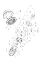
- a normally closed soundless hub assembly for a bicycle in accordance with the preferred embodiment of the present invention comprises a shaft 12, a hub body 40 rotatably mounted on the shaft 12, a driven ring 43 secured in the hub body 40 to drive the hub body 40 to rotate relative to the shaft 12 and having an inner wall provided with a plurality of oneway ratchet teeth 42, a drive seat 10 rotatably mounted on the shaft 12, a drive ring 13 secured on the drive seat 10 to move in concert with the drive seat 10 and having a periphery provided with a plurality of pressing grooves 131, a rotation ring 20 mounted on the drive ring 13 and having a periphery provided with a plurality of receiving slots 21, a plurality of pawl members 22 each pivotally mounted in a respective one of the receiving slots 21 of the rotation ring 20 to releasably mesh with the oneway ratchet teeth 42 of the driven ring 43, a plurality of push balls 23 each
- the drive seat 10 has an inner portion provided with a stepped shaft hole 16 rotatably mounted on the shaft 12 by at least one bearing 101.
- the drive seat 10 has an end face provided with a plurality of limit lugs 14 and a plurality of limit slots 15 located between the limit lugs 14 respectively.
- the drive seat 10 has an annular outer surface provided with a plurality of axially extending fixing channels 11 for mounting at least one freewheel (not shown). Alternatively, the freewheel is integrally formed on the drive seat 10.
- the rotation ring 20 has an inner portion provided with a mounting hole 28 rotatably mounted on the drive ring 13.
- Each of the receiving slots 21 of the rotation ring 20 has a first end provided with a receiving bore 212 connected between the mounting hole 28 and each of the receiving slots 21 and a second end provided with a pivot hole 211.
- the rotation ring 20 is provided with a plurality of positioning pieces 27 directed toward the damping ring 30.
- the rotation ring 20 is also provided with a plurality of limit ribs 24 which are movable in the limit slots 15 of the drive seat 10 respectively and are limited between the limit lugs 14 of the drive seat 10 respectively.
- the rotation ring 20 has an outer surface provided with an annular retaining groove 25 to retain the elastic member 26.
- the retaining groove 25 of the rotation ring 20 has a bottom wall provided with a fixing hole 251.
- Each of the pawl members 22 has a first end provided with an enlarged pivot shaft 221 pivotally mounted in the pivot hole 211 of the respective receiving slot 21 of the rotation ring 20 and a second end provided with a locking detent 224 which is movable by a respective one of the push balls 23 to mesh with the oneway ratchet teeth 42 of the driven ring 43.
- Each of the pawl members 22 has an outer surface provided with an elongate limit groove 223 to receive the elastic member 26.
- Each of the pawl members 22 has a side provided with a limit post 222 which are movable in the limit slots 15 of the drive seat 10 respectively and are limited between the limit lugs 14 of the drive seat 10 respectively.
- Each of the push balls 23 is movably mounted in a respective one of the receiving bore 212 of the rotation ring 20 and has a first side received in and pressed by the respective one pressing groove 131 of the drive ring 13 and a second side abutting the locking detent 224 of the respective pawl member 22 to push the locking detent 224 of the respective pawl member 22 toward the oneway ratchet teeth 42 of the driven ring 43.
- the elastic member 26 has a substantially C-shaped profile and has a side provided with an opening 262.
- the opening 262 of the elastic member 26 has an end provided with a bent fixing portion 261 inserted into the fixing hole 251 of the rotation ring 20 to fix the elastic member 26 onto the rotation ring 20.
- the damping ring 30 abuts the rotation ring 20 and has an outer wall provided with a plurality of positioning recesses 31 to fix the positioning pieces 27 of the rotation ring 20 respectively so that the damping ring 30 is combined with the rotation ring 20.
- the damping ring 30 has a periphery provided with a plurality of radially extending threaded receiving holes 33 connected to the mounting sleeve 32 to receive the tension adjusting mechanisms 37 respectively.
- Each of the tension adjusting mechanisms 37 includes a pressing ball 34 movably mounted in the respective receiving hole 33 of the damping ring 30 and pressing an outer wall of the mounting sleeve 32, an adjusting screw 36 screwed into the respective receiving hole 33 of the damping ring 30 and a push spring 35 mounted in the respective receiving hole 33 of the damping ring 30 and biased between the pressing ball 34 and the adjusting screw 36 to push the pressing ball 34 toward the mounting sleeve 32.
- the adjusting screw 36 is rotated and moved in the respective receiving hole 33 of the damping ring 30 to adjust the tension of the push spring 35.
- the hub body 40 has an inner portion provided with a stepped receiving space 41 rotatably mounted on the shaft 12 by a bearing 401 to receive the rotation ring 20, the damping ring 30 and the mounting sleeve 32.
- the driven ring 43 is secured in the receiving space 41 of the hub body 40 and surround the rotation ring 20 and the pawl members 22.
- the mounting sleeve 32 is inserted into the shaft hole 16 of the drive seat 10.
- the mounting sleeve 32 is located between the bearing 10 of the drive seat 10 and the bearing 401 of the hub body 40 so that the mounting sleeve 32 is located between the drive seat 10 and the hub body 40.
- the hub body 40 is connected to a wheel (not shown) of the bicycle, the shaft 12 is connected to a frame (not shown) of the bicycle, and the freewheel (not shown) on the drive seat 10 meshes with and is driven by a chain (not shown) which is driven by a chainwheel (not shown) which is driven by a pedal (not shown) that is pedalled by a rider.
- each of the pawl members 22 is initially pressed inward by the elastic member 26 to disengage the oneway ratchet teeth 42 of the driven ring 43, so that the driven ring 43 is released from and non-rotatable with the drive seat 10 at a normal state.
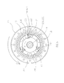
- each of the pressing grooves 131 of the drive ring 13 is moved to press each of the push balls 23 outwardly and to push the locking detent 224 of each of the pawl members 22 to mesh with the oneway ratchet teeth 42 of the driven ring 43 as shown in Figs. 4 and 5 so that each of the pawl members 22 is combined with the driven ring 43.
- the driven ring 43 is combined with the rotation ring 20 and the drive ring 13 by the pawl members 22, so that when the drive seat 10 is rotated forward relative to the shaft 12, the driven ring 43 is driven by the drive seat 10 to drive the hub body 40 to rotate forward relative to the shaft 12 so as to move the wheel forward.
- the chainwheel is driven by the pedal to drive the chain which drives the freewheel of the drive seat 10 so as to rotate the drive seat 10 backward relative to the shaft 12, so that the drive seat 10 is rotated backward relative to the shaft 12, and the drive ring 13 is also rotated backward relative to the shaft 12.
- the damping ring 30 frictionally mounted on the mounting sleeve 32 provides a damping force to the rotation movement of the rotation ring 20 so that the rotation ring 20 and the damping ring 30 will not be rotated by the drive ring 13.
- the driven ring 43 is released from the rotation ring 20 and the drive ring 13 by the pawl members 22, so that when the drive seat 10 is rotated backward relative to the shaft 12, the driven ring 43 together with the hub body 40 is not driven by the drive seat 10, and the drive seat 10 idles.
- each of the pawl members 22 is retracted into the respective receiving slot 21 of the rotation ring 20, and the locking detent 224 of each of the pawl members 22 disengages the oneway ratchet teeth 42 of the driven ring 43 constantly, so that each of the pawl members 22 will not touch the driven ring 43 when the pedal is driven backward to prevent from producing a noise when the pedal is driven backward.
- each of the pawl members 22 is separated from the driven ring 43 when the pedal is driven backward so that the hub body 40 is separated from the drive seat 10, and a backward rotation of the hub body 40 will not drive the drive seat 10 and the pedal to prevent the pedal from being driven when the hub body 40 is rotated backward.
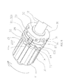
- the hub assembly further comprises a reinforcing sleeve 16 mounted on the drive ring 13 to reinforce the strength of the drive ring 13.
- the reinforcing sleeve 16 has a periphery provided with a plurality of pressing recesses 161 aligning with the pressing grooves 131 of the drive ring 13 respectively to receive and press the push balls 23 respectively.
- each of the pawl members 22 is retracted into the respective receiving slot 21 of the rotation ring 20 to disengage the oneway ratchet teeth 42 of the driven ring 43, so that each of the pawl members 22 is spaced from and will not touch the driven ring 43 when the pedal is driven backward so as to prevent from producing a noise when the pedal is driven backward.
- each of the pawl members 22 is driven by each of the push balls 23 in a rolling manner so that each of the pawl members 22 is moved smoothly and stably without incurring sliding friction to prevent each of the pawl members 22 from being rubbed or worn out, thereby facilitating operation of the drive seat 10, and thereby enhancing the lifetime of each of the pawl members 22.
- each of the tension adjusting mechanisms 37 is used to adjust the damping force of the damping ring 30, so that the damping force of the damping ring 30 is distributed evenly.
Abstract
Description
- The present invention relates to a hub and, more particularly, to a normally closed soundless ratchet hub assembly for a bicycle.
- A conventional hub assembly for a bicycle in accordance with the prior art shown in
Figs. 9 and10 comprises ashaft 53, ahub body 80 rotatably mounted on theshaft 53, a drivenring 82 secured in thehub body 80 to drive thehub body 80 to rotate relative to theshaft 53 and having an inner wall provided with a plurality ofoneway ratchet teeth 81, adrive seat 50 rotatably mounted on theshaft 53 and having an end face provided with a plurality ofdrive blocks 51 each having a surface provided with anoblique driving slot 52, asupport ring 54 secured on thedrive seat 50 and protruding from thedrive blocks 51, arotation ring 61 mounted on thesupport ring 54 and having a periphery provided with a plurality of receivingslots 611, a plurality ofpawl members 62 each pivotally mounted in a respective one of thereceiving slots 611 of therotation ring 61 to releasably mesh with theoneway ratchet teeth 81 of the drivenring 82 and each having a side provided with aguide post 621 which is movable in thedriving slot 52 of a respective one of thedrive blocks 51, amounting sleeve 74 mounted on theshaft 53, alimit ring 70 mounted on themounting sleeve 74 and attached to therotation ring 61 to rotate in concert with therotation ring 61, adamper 73 mounted on themounting sleeve 74 and pressing thelimit ring 70 to damp a rotation movement of therotation ring 61, and anelastic member 63 mounted on therotation ring 61 and pressing each of thepawl members 62 to detach each of thepawl members 62 from theoneway ratchet teeth 81 of the drivenring 82 at a normal state. - The
drive seat 50 has an outer surface provided with a plurality of axially extendingfixing channels 55 for mounting at least one freewheel (not shown). Thedriving slot 52 of each of thedrive blocks 51 has anouter side 522 and aninner side 521. Therotation ring 61 has an inner portion provided with amounting hole 64 rotatably mounted on thesupport ring 54. Each of thepawl members 62 has a first end provided with an enlargedpivot shaft 622 pivotally mounted in therespective receiving slot 611 of therotation ring 61 and a second end provided with a locking detent 623 which is movable with theguide post 621 to mesh with or detach from theoneway ratchet teeth 81 of the drivenring 82. The locking detent 623 of each of thepawl members 62 is in line with theguide post 621. Thelimit ring 70 has an inner portion provided with a stepped receivinghole 72 mounted on themounting sleeve 74 to receive thedamper 73. Thelimit ring 70 is located between thesupport ring 54 and themounting sleeve 74. Thedamper 73 is secured in thereceiving hole 72 of thelimit ring 70 and is located between thelimit ring 70 and themounting sleeve 74. Thedamper 73 is made of a resilient material and has aninner wall 730 closely fit onto themounting sleeve 74 and anouter wall 732 pressing thelimit ring 70 to provide a damping force to a rotation movement of thelimit ring 70. Themounting sleeve 74 is inserted into thedrive seat 50 and is located between thedrive seat 50 and thehub body 80. - In assembly, the
hub body 80 is connected to a wheel (not shown) of the bicycle, theshaft 53 is connected to a frame (not shown) of the bicycle, and the freewheel on thedrive seat 50 meshes with and is driven by a chain (not shown) which is driven by a chainwheel (not shown) which is driven by a pedal (not shown) that is pedalled by a rider. Thus, each of thepawl members 62 is initially pressed inward by theelastic member 63 to disengage theoneway ratchet teeth 81 of the drivenring 82, so that the drivenring 82 is released from and non-rotatable with thedrive seat 50 at a normal state. At this time, theguide post 621 of each of thepawl members 62 is located at theinner side 521 of thedriving slot 52 of therespective drive block 51. - In operation, when the pedal is pedalled by the rider, the chainwheel is driven by the pedal to drive the chain which drives the freewheel of the
drive seat 50 so as to rotate thedrive seat 50 forward, so that thedrive seat 50 is rotated forward relative to theshaft 53, and thedrive blocks 51 of thedrive seat 50 are also rotated forward relative to theshaft 53. At this time, thedamper 73 provides a damping force to the rotation movement of thelimit ring 70 so that therotation ring 61 and thelimit ring 70 will not be rotated with thedrive blocks 51 of thedrive seat 50. In such a manner, when thedrive blocks 51 of thedrive seat 50 are rotated forward relative to theshaft 53, theguide post 621 of each of thepawl members 62 is moved from theinner side 521 to theouter side 522 of thedriving slot 52 of therespective drive block 51, and each of thepawl members 62 is pivoted outwardly relative to the respective receivingslot 611 of therotation ring 61, so that the locking detent 623 of each of thepawl members 62 is also moved outwardly to mesh with theoneway ratchet teeth 81 of the drivenring 82. Thus, the drivenring 82 is combined with therotation ring 61 and thedrive blocks 51 of thedrive seat 50 by thepawl members 62, so that when thedrive seat 50 is rotated forward relative to theshaft 53, the drivenring 82 is driven by thedrive seat 50 to drive thehub body 80 to rotate forward relative to theshaft 53 so as to move the wheel forward. - On the contrary, when the pedal is pedalled by the rider to move backward, the chainwheel is driven by the pedal to drive the chain which drives the freewheel of the
drive seat 50 so as to rotate thedrive seat 50 backward relative to theshaft 53, so that thedrive seat 50 is rotated backward relative to theshaft 53, and thedrive blocks 51 of thedrive seat 50 are also rotated backward relative to theshaft 53. At this time, thedamper 73 provides a damping force to the rotation movement of thelimit ring 70 so that therotation ring 61 and thelimit ring 70 will not be rotated with thedrive blocks 51 of thedrive seat 50. In such a manner, when thedrive blocks 51 of thedrive seat 50 are rotated backward relative to theshaft 53, theguide post 621 of each of thepawl members 62 is moved from theouter side 522 to theinner side 521 of thedriving slot 52 of therespective drive block 51, and each of thepawl members 62 is pivoted inwardly to retract into the respectivereceiving slot 611 of therotation ring 61, so that the locking detent 623 of each of thepawl members 62 is also moved inwardly to disengage theoneway ratchet teeth 81 of the drivenring 82. Thus, the drivenring 82 is released from therotation ring 61 and thedrive blocks 51 of thedrive seat 50 by thepawl members 62, so that when thedrive seat 50 is rotated backward relative to theshaft 53, the drivenring 82 together with thehub body 80 is not driven by thedrive seat 50, and thedrive seat 50 idles. - Thus, when the
drive seat 50 is rotated backward by the pedal, each of thepawl members 62 is retracted into the respective receivingslot 611 of therotation ring 61, and the locking detent 623 of each of thepawl members 62 disengages theoneway ratchet teeth 81 of the drivenring 82 constantly, so that each of thepawl members 62 will not touch the drivenring 82 when the pedal is driven backward to prevent from producing a noise when the pedal is driven backward. In addition, each of thepawl members 62 is separated from the drivenring 82 when the pedal is driven backward so that thehub body 80 is separated from thedrive seat 50, and a backward rotation of thehub body 80 will not drive thedrive seat 50 and the pedal to prevent the pedal from being driven when thehub body 80 is rotated backward. - However, a sliding friction is produced between the
guide post 621 of each of thepawl members 62 and thedriving slot 52 of therespective drive block 51 during movement of thedrive seat 50, so that thedrive seat 50 is not operated smoothly and stably. In addition, thedamper 73 is made of an annular elastic plate so that thedamper 73 has an unevenly distributed tension and easily produces an elastic fatigue. - In accordance with the present invention, there is provided a hub assembly for a bicycle, comprising a shaft, a hub body rotatably mounted on the shaft, a driven ring secured in the hub body and having an inner wall provided with a plurality of oneway ratchet teeth, a drive seat rotatably mounted on the shaft, a drive ring secured on the drive seat and having a periphery provided with a plurality of pressing grooves, a rotation ring mounted on the drive ring and having a periphery provided with a plurality of receiving slots, a plurality of pawl members each pivotally mounted in a respective one of the receiving slots of the rotation ring to releasably mesh with the oneway ratchet teeth of the driven ring, a plurality of push balls each movably mounted on the rotation ring and each biased between a respective one of the pressing grooves of the drive ring and a respective one of the pawl members to push the respective pawl member toward the oneway ratchet teeth of the driven ring, a mounting sleeve mounted on the shaft, a damping ring mounted on the mounting sleeve and attached to the rotation ring to damp a rotation movement of the rotation ring, and a plurality of tension adjusting mechanisms each biased between the damping ring and the mounting sleeve to adjust a damping force of the damping ring.
- Each of the receiving slots of the rotation ring has a first end provided with a receiving bore connected between the drive ring and each of the receiving slots. Each of the push balls is movably mounted in a respective one of the receiving bore of the rotation ring and has a first side received in and pressed by the respective one pressing groove of the drive ring and a second side abutting the respective pawl member. The rotation ring is provided with a plurality of positioning pieces. The damping ring has an outer wall provided with a plurality of positioning recesses to fix the positioning pieces of the rotation ring respectively. The damping ring has a periphery provided with a plurality of threaded receiving holes connected to the mounting sleeve to receive the tension adjusting mechanisms respectively. Each of the tension adjusting mechanisms includes a pressing ball movably mounted in the respective receiving hole of the damping ring and pressing an outer wall of the mounting sleeve, an adjusting screw screwed into the respective receiving hole of the damping ring and a push spring mounted in the respective receiving hole of the damping ring and biased between the pressing ball and the adjusting screw. The hub body has an inner portion provided with a receiving space to receive the rotation ring and the damping ring.
- According to the primary objective of the present invention, each of the pawl members is driven by each of the push balls in a rolling manner so that each of the pawl members is moved smoothly and stably without incurring sliding friction to prevent each of the pawl members from being rubbed or worn out, thereby facilitating operation of the drive seat, and thereby enhancing the lifetime of each of the pawl members.
- According to another objective of the present invention, each of the tension adjusting mechanisms is used to adjust the damping force of the damping ring, so that the damping force of the damping ring is distributed evenly.
- Further benefits and advantages of the present invention will become apparent after a careful reading of the detailed description with appropriate reference to the accompanying drawings.
- In the drawings:
-
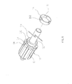
Fig. 1 is a perspective view of a hub assembly for a bicycle in accordance with the preferred embodiment of the present invention. -
Fig. 2 is an exploded perspective view of the hub assembly as shown inFig. 1 . -
Fig. 3 is a front cross-sectional view of the hub assembly as shown inFig. 1 . -
Fig. 4 is a partially perspective view of the hub assembly as shown inFig. 1 . -
Fig. 5 is a cross-sectional view of the hub assembly taken along line 5-5 as shown inFig. 3 . -
Fig. 6 is a schematic operational view of the hub assembly as shown inFig. 4 . -
Fig. 7 is a schematic operational view of the hub assembly as shown inFig. 5 . -
Fig. 8 is a partially exploded perspective view of a hub assembly for a bicycle in accordance with another preferred embodiment of the present invention. -
Fig. 9 is an exploded perspective view of a conventional hub assembly for a bicycle in accordance with the prior art. -
Fig. 10 is a side cross-sectional assembly view of the conventional hub assembly as shown inFig. 9 . - Referring to the drawings and initially to
Figs. 1-5 , a normally closed soundless hub assembly for a bicycle in accordance with the preferred embodiment of the present invention comprises ashaft 12, ahub body 40 rotatably mounted on theshaft 12, a drivenring 43 secured in thehub body 40 to drive thehub body 40 to rotate relative to theshaft 12 and having an inner wall provided with a plurality ofoneway ratchet teeth 42, adrive seat 10 rotatably mounted on theshaft 12, adrive ring 13 secured on thedrive seat 10 to move in concert with thedrive seat 10 and having a periphery provided with a plurality ofpressing grooves 131, arotation ring 20 mounted on thedrive ring 13 and having a periphery provided with a plurality of receivingslots 21, a plurality ofpawl members 22 each pivotally mounted in a respective one of thereceiving slots 21 of therotation ring 20 to releasably mesh with theoneway ratchet teeth 42 of the drivenring 43, a plurality ofpush balls 23 each movably mounted on therotation ring 20 and each biased between a respective one of thepressing grooves 131 of thedrive ring 13 and a respective one of thepawl members 22 to push therespective pawl member 22 toward theoneway ratchet teeth 42 of the drivenring 43, amounting sleeve 32 mounted on theshaft 12, adamping ring 30 frictionally mounted on themounting sleeve 32 and attached to therotation ring 20 to damp a rotation movement of therotation ring 20, a plurality oftension adjusting mechanisms 37 each biased between thedamping ring 30 and themounting sleeve 32 to adjust a damping force of thedamping ring 30, and anelastic member 26 mounted on therotation ring 20 and pressing each of thepawl members 22 to detach each of thepawl members 22 from theoneway ratchet teeth 42 of the drivenring 43 at a normal state. - The
drive seat 10 has an inner portion provided with astepped shaft hole 16 rotatably mounted on theshaft 12 by at least one bearing 101. Thedrive seat 10 has an end face provided with a plurality oflimit lugs 14 and a plurality oflimit slots 15 located between thelimit lugs 14 respectively. Thedrive seat 10 has an annular outer surface provided with a plurality of axially extendingfixing channels 11 for mounting at least one freewheel (not shown). Alternatively, the freewheel is integrally formed on thedrive seat 10. - The
rotation ring 20 has an inner portion provided with amounting hole 28 rotatably mounted on thedrive ring 13. Each of thereceiving slots 21 of therotation ring 20 has a first end provided with a receivingbore 212 connected between themounting hole 28 and each of thereceiving slots 21 and a second end provided with apivot hole 211. Therotation ring 20 is provided with a plurality ofpositioning pieces 27 directed toward thedamping ring 30. Therotation ring 20 is also provided with a plurality oflimit ribs 24 which are movable in thelimit slots 15 of thedrive seat 10 respectively and are limited between thelimit lugs 14 of thedrive seat 10 respectively. Therotation ring 20 has an outer surface provided with anannular retaining groove 25 to retain theelastic member 26. Theretaining groove 25 of therotation ring 20 has a bottom wall provided with afixing hole 251. - Each of the
pawl members 22 has a first end provided with an enlargedpivot shaft 221 pivotally mounted in thepivot hole 211 of the respective receivingslot 21 of therotation ring 20 and a second end provided with alocking detent 224 which is movable by a respective one of thepush balls 23 to mesh with theoneway ratchet teeth 42 of the drivenring 43. Each of thepawl members 22 has an outer surface provided with anelongate limit groove 223 to receive theelastic member 26. Each of thepawl members 22 has a side provided with alimit post 222 which are movable in thelimit slots 15 of thedrive seat 10 respectively and are limited between thelimit lugs 14 of thedrive seat 10 respectively. - Each of the
push balls 23 is movably mounted in a respective one of thereceiving bore 212 of therotation ring 20 and has a first side received in and pressed by the respective onepressing groove 131 of thedrive ring 13 and a second side abutting the locking detent 224 of therespective pawl member 22 to push the locking detent 224 of therespective pawl member 22 toward theoneway ratchet teeth 42 of the drivenring 43. - The
elastic member 26 has a substantially C-shaped profile and has a side provided with anopening 262. Theopening 262 of theelastic member 26 has an end provided with abent fixing portion 261 inserted into the fixinghole 251 of therotation ring 20 to fix theelastic member 26 onto therotation ring 20. - The damping
ring 30 abuts therotation ring 20 and has an outer wall provided with a plurality of positioning recesses 31 to fix thepositioning pieces 27 of therotation ring 20 respectively so that the dampingring 30 is combined with therotation ring 20. The dampingring 30 has a periphery provided with a plurality of radially extending threaded receivingholes 33 connected to the mountingsleeve 32 to receive thetension adjusting mechanisms 37 respectively. - Each of the
tension adjusting mechanisms 37 includes apressing ball 34 movably mounted in the respective receivinghole 33 of the dampingring 30 and pressing an outer wall of the mountingsleeve 32, an adjustingscrew 36 screwed into the respective receivinghole 33 of the dampingring 30 and apush spring 35 mounted in the respective receivinghole 33 of the dampingring 30 and biased between thepressing ball 34 and the adjustingscrew 36 to push thepressing ball 34 toward the mountingsleeve 32. The adjustingscrew 36 is rotated and moved in the respective receivinghole 33 of the dampingring 30 to adjust the tension of thepush spring 35. - The
hub body 40 has an inner portion provided with a stepped receivingspace 41 rotatably mounted on theshaft 12 by abearing 401 to receive therotation ring 20, the dampingring 30 and the mountingsleeve 32. The drivenring 43 is secured in the receivingspace 41 of thehub body 40 and surround therotation ring 20 and thepawl members 22. - The mounting
sleeve 32 is inserted into theshaft hole 16 of thedrive seat 10. The mountingsleeve 32 is located between the bearing 10 of thedrive seat 10 and the bearing 401 of thehub body 40 so that the mountingsleeve 32 is located between thedrive seat 10 and thehub body 40. - In assembly, the
hub body 40 is connected to a wheel (not shown) of the bicycle, theshaft 12 is connected to a frame (not shown) of the bicycle, and the freewheel (not shown) on thedrive seat 10 meshes with and is driven by a chain (not shown) which is driven by a chainwheel (not shown) which is driven by a pedal (not shown) that is pedalled by a rider. Thus, each of thepawl members 22 is initially pressed inward by theelastic member 26 to disengage theoneway ratchet teeth 42 of the drivenring 43, so that the drivenring 43 is released from and non-rotatable with thedrive seat 10 at a normal state. - In operation, referring to
Figs. 4-7 with reference toFigs. 1-3 , when the pedal is pedalled by the rider, the chainwheel is driven by the pedal to drive the chain which drives the freewheel of thedrive seat 10 so as to rotate thedrive seat 10 forward, so that thedrive seat 10 is rotated forward relative to theshaft 12, and thedrive ring 13 is also rotated forward relative to theshaft 12. At this time, the dampingring 30 frictionally mounted on the mountingsleeve 32 provides a damping force to the rotation movement of therotation ring 20 so that therotation ring 20 and the dampingring 30 will not be rotated by thedrive ring 13. In such a manner, when thedrive ring 13 is rotated forward relative to theshaft 12, each of thepressing grooves 131 of thedrive ring 13 is moved to press each of thepush balls 23 outwardly and to push thelocking detent 224 of each of thepawl members 22 to mesh with theoneway ratchet teeth 42 of the drivenring 43 as shown inFigs. 4 and5 so that each of thepawl members 22 is combined with the drivenring 43. Thus, the drivenring 43 is combined with therotation ring 20 and thedrive ring 13 by thepawl members 22, so that when thedrive seat 10 is rotated forward relative to theshaft 12, the drivenring 43 is driven by thedrive seat 10 to drive thehub body 40 to rotate forward relative to theshaft 12 so as to move the wheel forward. - On the contrary, when the pedal is pedalled by the rider to move backward, the chainwheel is driven by the pedal to drive the chain which drives the freewheel of the
drive seat 10 so as to rotate thedrive seat 10 backward relative to theshaft 12, so that thedrive seat 10 is rotated backward relative to theshaft 12, and thedrive ring 13 is also rotated backward relative to theshaft 12. At this time, the dampingring 30 frictionally mounted on the mountingsleeve 32 provides a damping force to the rotation movement of therotation ring 20 so that therotation ring 20 and the dampingring 30 will not be rotated by thedrive ring 13. In such a manner, when thedrive ring 13 is rotated backward relative to theshaft 12, each of thepressing grooves 131 of thedrive ring 13 is moved backward to receive and retract each of thepush balls 23, and thelocking detent 224 of each of thepawl members 22 is pressed inward by theelastic member 26 and is detached from theoneway ratchet teeth 42 of the drivenring 43 as shown inFigs. 6 and7 so that each of thepawl members 22 is detached from the drivenring 43. Thus, the drivenring 43 is released from therotation ring 20 and thedrive ring 13 by thepawl members 22, so that when thedrive seat 10 is rotated backward relative to theshaft 12, the drivenring 43 together with thehub body 40 is not driven by thedrive seat 10, and thedrive seat 10 idles. - Thus, when the
drive seat 10 is rotated backward by the pedal, each of thepawl members 22 is retracted into therespective receiving slot 21 of therotation ring 20, and thelocking detent 224 of each of thepawl members 22 disengages theoneway ratchet teeth 42 of the drivenring 43 constantly, so that each of thepawl members 22 will not touch the drivenring 43 when the pedal is driven backward to prevent from producing a noise when the pedal is driven backward. In addition, each of thepawl members 22 is separated from the drivenring 43 when the pedal is driven backward so that thehub body 40 is separated from thedrive seat 10, and a backward rotation of thehub body 40 will not drive thedrive seat 10 and the pedal to prevent the pedal from being driven when thehub body 40 is rotated backward. - Referring to
Fig. 8 , the hub assembly further comprises a reinforcingsleeve 16 mounted on thedrive ring 13 to reinforce the strength of thedrive ring 13. The reinforcingsleeve 16 has a periphery provided with a plurality ofpressing recesses 161 aligning with thepressing grooves 131 of thedrive ring 13 respectively to receive and press thepush balls 23 respectively. - Accordingly, when the
drive seat 10 is rotated backward by the pedal, each of thepawl members 22 is retracted into therespective receiving slot 21 of therotation ring 20 to disengage theoneway ratchet teeth 42 of the drivenring 43, so that each of thepawl members 22 is spaced from and will not touch the drivenring 43 when the pedal is driven backward so as to prevent from producing a noise when the pedal is driven backward. In addition, each of thepawl members 22 is driven by each of thepush balls 23 in a rolling manner so that each of thepawl members 22 is moved smoothly and stably without incurring sliding friction to prevent each of thepawl members 22 from being rubbed or worn out, thereby facilitating operation of thedrive seat 10, and thereby enhancing the lifetime of each of thepawl members 22. Further, each of thetension adjusting mechanisms 37 is used to adjust the damping force of the dampingring 30, so that the damping force of the dampingring 30 is distributed evenly. - Although the invention has been explained in relation to its preferred embodiment(s) as mentioned above, it is to be understood that many other possible modifications and variations can be made without departing from the scope of the present invention. It is, therefore, contemplated that the appended claim or claims will cover such modifications and variations that fall within the true scope of the invention.
Claims (9)
- A hub assembly for a bicycle, comprising:a shaft (12);a hub body (40) rotatably mounted on the shaft;a driven ring (43) secured in the hub body and having an inner wall provided with a plurality of oneway ratchet teeth (42);a drive seat (10) rotatably mounted on the shaft;a drive ring (13) secured on the drive seat and having a periphery provided with a plurality of pressing grooves (131);a rotation ring (20) mounted on the drive ring and having a periphery provided with a plurality of receiving slots (21);a plurality of pawl members (22) each pivotally mounted in a respective one of the receiving slots of the rotation ring to releasably mesh with the oneway ratchet teeth of the driven ring;a plurality of push balls (23) each movably mounted on the rotation ring and each biased between a respective one of the pressing grooves of the drive ring and a respective one of the pawl members to push the respective pawl member toward the oneway ratchet teeth of the driven ring;a mounting sleeve (32) mounted on the shaft;a damping ring (30) mounted on the mounting sleeve and attached to the rotation ring to damp a rotation movement of the rotation ring;a plurality of tension adjusting mechanisms (37) each biased between the damping ring and the mounting sleeve to adjust a damping force of the damping ring;wherein each of the receiving slots of the rotation ring has a first end provided with a receiving bore (212) connected between the drive ring and each of the receiving slots;
each of the push balls is movably mounted in a respective one of the receiving bore of the rotation ring and has a first side received in and pressed by the respective one pressing groove of the drive ring and a second side abutting the respective pawl member;
the rotation ring is provided with a plurality of positioning pieces (27);
the damping ring has an outer wall provided with a plurality of positioning recesses (31) to fix the positioning pieces of the rotation ring respectively;
the damping ring has a periphery provided with a plurality of threaded receiving holes (33) connected to the mounting sleeve to receive the tension adjusting mechanisms respectively;
each of the tension adjusting mechanisms includes:a pressing ball (34) movably mounted in the respective receiving hole of the damping ring and pressing an outer wall of the mounting sleeve;an adjusting screw (36) screwed into the respective receiving hole of the damping ring; anda push spring (35) mounted in the respective receiving hole of the damping ring and biased between the pressing ball and the adjusting screw;the hub body has an inner portion provided with a receiving space (4 1 ) to receive the rotation ring and the damping ring. - The hub assembly of claim 1, wherein the drive seat has an annular outer surface provided with a plurality of axially extending fixing channels (11).
- The hub assembly of claim 1, wherein
the drive seat has an end face provided with a plurality of limit lugs (14) and a plurality of limit slots (15) located between the limit lugs respectively;
the rotation ring is provided with a plurality of limit ribs (24) which are movable in the limit slots of the drive seat respectively and are limited between the limit lugs of the drive seat respectively. - The hub assembly of claim 1, wherein
the drive seat has an end face provided with a plurality of limit lugs and a plurality of limit slots located between the limit lugs respectively;
each of the pawl members has a side provided with a limit post (222) which are movable in the limit slots of the drive seat respectively and are limited between the limit lugs of the drive seat respectively. - The hub assembly of claim 1, wherein
each of the receiving slots of the rotation ring has a second end provided with a pivot hole (211);
each of the pawl members has a first end provided with a pivot shaft (221 ) pivotally mounted in the pivot hole of the respective receiving slot of the rotation ring and a second end provided with a locking detent (224) which is movable by a respective one of the push balls to mesh with the oneway ratchet teeth of the driven ring. - The hub assembly of claim 1, wherein
the hub assembly further comprises an elastic member (26) mounted on the rotation ring and pressing each of the pawl members to detach each of the pawl members from the oneway ratchet teeth of the driven ring at a normal state;
the rotation ring has an outer surface provided with an annular retaining groove (25) to retain the elastic member;
each of the pawl members has an outer surface provided with an elongate limit groove (223) to receive the elastic member. - The hub assembly of claim 6, wherein
the retaining groove of the rotation ring has a bottom wall provided with a fixing hole (251);
the elastic member has a side provided with an opening (262);
the opening of the elastic member has an end provided with a bent fixing portion (261) inserted into the fixing hole of the rotation ring to fix the elastic member onto the rotation ring. - The hub assembly of claim 1, wherein
the drive seat is mounted on the shaft by at least one bearing (101); the hub body is mounted on the shaft by a bearing (401);
the mounting sleeve is located between the bearing of the drive seat and the bearing of the hub body so that the mounting sleeve is located between the drive seat and the hub body. - The hub assembly of claim 1, wherein
the hub assembly further comprises a reinforcing sleeve (16) mounted on the drive ring to reinforce the strength of the drive ring;
the reinforcing sleeve has a periphery provided with a plurality of pressing recesses (161) aligning with the pressing grooves of the drive ring respectively to receive and press the push balls respectively.
Priority Applications (1)
| Application Number | Priority Date | Filing Date | Title |
|---|---|---|---|
| EP20090180824 EP2340945B1 (en) | 2009-12-28 | 2009-12-28 | Normally closed soundless bicycle hub |
Applications Claiming Priority (1)
| Application Number | Priority Date | Filing Date | Title |
|---|---|---|---|
| EP20090180824 EP2340945B1 (en) | 2009-12-28 | 2009-12-28 | Normally closed soundless bicycle hub |
Publications (2)
| Publication Number | Publication Date |
|---|---|
| EP2340945A1 true EP2340945A1 (en) | 2011-07-06 |
| EP2340945B1 EP2340945B1 (en) | 2012-05-23 |
Family
ID=42167748
Family Applications (1)
| Application Number | Title | Priority Date | Filing Date |
|---|---|---|---|
| EP20090180824 Not-in-force EP2340945B1 (en) | 2009-12-28 | 2009-12-28 | Normally closed soundless bicycle hub |
Country Status (1)
| Country | Link |
|---|---|
| EP (1) | EP2340945B1 (en) |
Cited By (1)
| Publication number | Priority date | Publication date | Assignee | Title |
|---|---|---|---|---|
| DE102017120113B3 (en) | 2017-08-31 | 2019-02-14 | Chosen Co., Ltd. | Structurally reinforced locking mechanism for a bicycle hub |
Families Citing this family (1)
| Publication number | Priority date | Publication date | Assignee | Title |
|---|---|---|---|---|
| US11226016B1 (en) * | 2020-11-11 | 2022-01-18 | Driven Innovations Ltd. | Automatic free-coasting freewheel apparatus |
Citations (5)
| Publication number | Priority date | Publication date | Assignee | Title |
|---|---|---|---|---|
| GB1135818A (en) | 1966-06-10 | 1968-12-04 | Honda Gijutsu Kenkyusho Kk | Improvements in or relating to free wheel mechanisms |
| EP0549570A2 (en) | 1989-02-17 | 1993-06-30 | Shimano Industrial Co., Ltd. | Change-speed hub |
| EP1881221A2 (en) | 2006-07-21 | 2008-01-23 | Shimano Inc. | Bicycle freewheel |
| CN101549738A (en) | 2008-03-31 | 2009-10-07 | 乔绅股份有限公司 | Ratchet structure of hub |
| JP2009269435A (en) | 2008-05-02 | 2009-11-19 | Chosen Co Ltd | Hub ratchet structure |
-
2009
- 2009-12-28 EP EP20090180824 patent/EP2340945B1/en not_active Not-in-force
Patent Citations (5)
| Publication number | Priority date | Publication date | Assignee | Title |
|---|---|---|---|---|
| GB1135818A (en) | 1966-06-10 | 1968-12-04 | Honda Gijutsu Kenkyusho Kk | Improvements in or relating to free wheel mechanisms |
| EP0549570A2 (en) | 1989-02-17 | 1993-06-30 | Shimano Industrial Co., Ltd. | Change-speed hub |
| EP1881221A2 (en) | 2006-07-21 | 2008-01-23 | Shimano Inc. | Bicycle freewheel |
| CN101549738A (en) | 2008-03-31 | 2009-10-07 | 乔绅股份有限公司 | Ratchet structure of hub |
| JP2009269435A (en) | 2008-05-02 | 2009-11-19 | Chosen Co Ltd | Hub ratchet structure |
Cited By (1)
| Publication number | Priority date | Publication date | Assignee | Title |
|---|---|---|---|---|
| DE102017120113B3 (en) | 2017-08-31 | 2019-02-14 | Chosen Co., Ltd. | Structurally reinforced locking mechanism for a bicycle hub |
Also Published As
| Publication number | Publication date |
|---|---|
| EP2340945B1 (en) | 2012-05-23 |
Similar Documents
| Publication | Publication Date | Title |
|---|---|---|
| US8127909B2 (en) | Normally closed hub assembly for bicycle | |
| US8276731B2 (en) | Normally closed soundless bicycle hub | |
| US7938242B2 (en) | Bicycle hub that will not drive the pedal and will not produce noise when the hub is rotated in the backward direction | |
| US9669656B2 (en) | Bicycle freewheel | |
| US20170267024A1 (en) | Bicycle ratchet hub assembly without resilient part | |
| CN208630792U (en) | Bicycle chain puller | |
| ES2531851T3 (en) | Constructive group of bicycle hub with a rotor that has a front teeth | |
| US20100326247A1 (en) | Replacement structure of ratchet wrench | |
| US20150060224A1 (en) | Driving device for a hub | |
| US7445296B1 (en) | Bicycle hub having enhanced strength | |
| US8556055B2 (en) | Driving apparatus for rear hub of bicycle | |
| EP2340945A1 (en) | Normally closed soundless bicycle hub | |
| US8336694B2 (en) | Bicycle hub assembly with quickly switching function | |
| CN101952071A (en) | Reciprocating tool foot locking arrangement | |
| US20120228923A1 (en) | Two-direction hub assembly | |
| US20070254758A1 (en) | Hub assembly for bicycle | |
| EP2298576B1 (en) | Normally closed soundless bicycle hub | |
| EP2204291B1 (en) | Bicycle hub that will not drive the pedal and will not produce noise when the hub is rotated in the backward direction | |
| US20110220450A1 (en) | Hub ratchet driving device for bicycles | |
| TWM247372U (en) | Gear box for power tool | |
| US7111719B1 (en) | Hub clutch device for bicycle | |
| US20180264880A1 (en) | Quick release device for bicycle wheel | |
| US7765896B1 (en) | Reversible ratchet wrench whose operation directions are changed easily and quickly | |
| US11208171B2 (en) | Drive assembly for a bicycle | |
| EP1872971B1 (en) | Bicycle hub having shorter idle rotation distance |
Legal Events
| Date | Code | Title | Description |
|---|---|---|---|
| PUAI | Public reference made under article 153(3) epc to a published international application that has entered the european phase |
Free format text: ORIGINAL CODE: 0009012 |
|
| 17P | Request for examination filed |
Effective date: 20101118 |
|
| AK | Designated contracting states |
Kind code of ref document: A1 Designated state(s): AT BE BG CH CY CZ DE DK EE ES FI FR GB GR HR HU IE IS IT LI LT LU LV MC MK MT NL NO PL PT RO SE SI SK SM TR |
|
| AX | Request for extension of the european patent |
Extension state: AL BA RS |
|
| GRAP | Despatch of communication of intention to grant a patent |
Free format text: ORIGINAL CODE: EPIDOSNIGR1 |
|
| GRAS | Grant fee paid |
Free format text: ORIGINAL CODE: EPIDOSNIGR3 |
|
| GRAA | (expected) grant |
Free format text: ORIGINAL CODE: 0009210 |
|
| AK | Designated contracting states |
Kind code of ref document: B1 Designated state(s): AT BE BG CH CY CZ DE DK EE ES FI FR GB GR HR HU IE IS IT LI LT LU LV MC MK MT NL NO PL PT RO SE SI SK SM TR |
|
| REG | Reference to a national code |
Ref country code: GB Ref legal event code: FG4D |
|
| REG | Reference to a national code |
Ref country code: CH Ref legal event code: EP |
|
| REG | Reference to a national code |
Ref country code: AT Ref legal event code: REF Ref document number: 558896 Country of ref document: AT Kind code of ref document: T Effective date: 20120615 |
|
| REG | Reference to a national code |
Ref country code: IE Ref legal event code: FG4D |
|
| REG | Reference to a national code |
Ref country code: DE Ref legal event code: R096 Ref document number: 602009007189 Country of ref document: DE Effective date: 20120726 |
|
| REG | Reference to a national code |
Ref country code: NL Ref legal event code: T3 |
|
| REG | Reference to a national code |
Ref country code: LT Ref legal event code: MG4D Effective date: 20120523 |
|
| PG25 | Lapsed in a contracting state [announced via postgrant information from national office to epo] |
Ref country code: IS Free format text: LAPSE BECAUSE OF FAILURE TO SUBMIT A TRANSLATION OF THE DESCRIPTION OR TO PAY THE FEE WITHIN THE PRESCRIBED TIME-LIMIT Effective date: 20120923 Ref country code: FI Free format text: LAPSE BECAUSE OF FAILURE TO SUBMIT A TRANSLATION OF THE DESCRIPTION OR TO PAY THE FEE WITHIN THE PRESCRIBED TIME-LIMIT Effective date: 20120523 Ref country code: SE Free format text: LAPSE BECAUSE OF FAILURE TO SUBMIT A TRANSLATION OF THE DESCRIPTION OR TO PAY THE FEE WITHIN THE PRESCRIBED TIME-LIMIT Effective date: 20120523 Ref country code: CY Free format text: LAPSE BECAUSE OF FAILURE TO SUBMIT A TRANSLATION OF THE DESCRIPTION OR TO PAY THE FEE WITHIN THE PRESCRIBED TIME-LIMIT Effective date: 20120523 Ref country code: NO Free format text: LAPSE BECAUSE OF FAILURE TO SUBMIT A TRANSLATION OF THE DESCRIPTION OR TO PAY THE FEE WITHIN THE PRESCRIBED TIME-LIMIT Effective date: 20120823 Ref country code: LT Free format text: LAPSE BECAUSE OF FAILURE TO SUBMIT A TRANSLATION OF THE DESCRIPTION OR TO PAY THE FEE WITHIN THE PRESCRIBED TIME-LIMIT Effective date: 20120523 |
|
| REG | Reference to a national code |
Ref country code: AT Ref legal event code: MK05 Ref document number: 558896 Country of ref document: AT Kind code of ref document: T Effective date: 20120523 |
|
| PG25 | Lapsed in a contracting state [announced via postgrant information from national office to epo] |
Ref country code: SI Free format text: LAPSE BECAUSE OF FAILURE TO SUBMIT A TRANSLATION OF THE DESCRIPTION OR TO PAY THE FEE WITHIN THE PRESCRIBED TIME-LIMIT Effective date: 20120523 Ref country code: GR Free format text: LAPSE BECAUSE OF FAILURE TO SUBMIT A TRANSLATION OF THE DESCRIPTION OR TO PAY THE FEE WITHIN THE PRESCRIBED TIME-LIMIT Effective date: 20120824 Ref country code: HR Free format text: LAPSE BECAUSE OF FAILURE TO SUBMIT A TRANSLATION OF THE DESCRIPTION OR TO PAY THE FEE WITHIN THE PRESCRIBED TIME-LIMIT Effective date: 20120523 Ref country code: LV Free format text: LAPSE BECAUSE OF FAILURE TO SUBMIT A TRANSLATION OF THE DESCRIPTION OR TO PAY THE FEE WITHIN THE PRESCRIBED TIME-LIMIT Effective date: 20120523 Ref country code: PT Free format text: LAPSE BECAUSE OF FAILURE TO SUBMIT A TRANSLATION OF THE DESCRIPTION OR TO PAY THE FEE WITHIN THE PRESCRIBED TIME-LIMIT Effective date: 20120924 |
|
| PG25 | Lapsed in a contracting state [announced via postgrant information from national office to epo] |
Ref country code: BE Free format text: LAPSE BECAUSE OF FAILURE TO SUBMIT A TRANSLATION OF THE DESCRIPTION OR TO PAY THE FEE WITHIN THE PRESCRIBED TIME-LIMIT Effective date: 20120523 |
|
| PG25 | Lapsed in a contracting state [announced via postgrant information from national office to epo] |
Ref country code: DK Free format text: LAPSE BECAUSE OF FAILURE TO SUBMIT A TRANSLATION OF THE DESCRIPTION OR TO PAY THE FEE WITHIN THE PRESCRIBED TIME-LIMIT Effective date: 20120523 Ref country code: AT Free format text: LAPSE BECAUSE OF FAILURE TO SUBMIT A TRANSLATION OF THE DESCRIPTION OR TO PAY THE FEE WITHIN THE PRESCRIBED TIME-LIMIT Effective date: 20120523 Ref country code: CZ Free format text: LAPSE BECAUSE OF FAILURE TO SUBMIT A TRANSLATION OF THE DESCRIPTION OR TO PAY THE FEE WITHIN THE PRESCRIBED TIME-LIMIT Effective date: 20120523 Ref country code: EE Free format text: LAPSE BECAUSE OF FAILURE TO SUBMIT A TRANSLATION OF THE DESCRIPTION OR TO PAY THE FEE WITHIN THE PRESCRIBED TIME-LIMIT Effective date: 20120523 Ref country code: SK Free format text: LAPSE BECAUSE OF FAILURE TO SUBMIT A TRANSLATION OF THE DESCRIPTION OR TO PAY THE FEE WITHIN THE PRESCRIBED TIME-LIMIT Effective date: 20120523 Ref country code: RO Free format text: LAPSE BECAUSE OF FAILURE TO SUBMIT A TRANSLATION OF THE DESCRIPTION OR TO PAY THE FEE WITHIN THE PRESCRIBED TIME-LIMIT Effective date: 20120523 |
|
| PG25 | Lapsed in a contracting state [announced via postgrant information from national office to epo] |
Ref country code: PL Free format text: LAPSE BECAUSE OF FAILURE TO SUBMIT A TRANSLATION OF THE DESCRIPTION OR TO PAY THE FEE WITHIN THE PRESCRIBED TIME-LIMIT Effective date: 20120523 |
|
| PLBE | No opposition filed within time limit |
Free format text: ORIGINAL CODE: 0009261 |
|
| STAA | Information on the status of an ep patent application or granted ep patent |
Free format text: STATUS: NO OPPOSITION FILED WITHIN TIME LIMIT |
|
| 26N | No opposition filed |
Effective date: 20130226 |
|
| REG | Reference to a national code |
Ref country code: DE Ref legal event code: R097 Ref document number: 602009007189 Country of ref document: DE Effective date: 20130226 |
|
| PG25 | Lapsed in a contracting state [announced via postgrant information from national office to epo] |
Ref country code: BG Free format text: LAPSE BECAUSE OF FAILURE TO SUBMIT A TRANSLATION OF THE DESCRIPTION OR TO PAY THE FEE WITHIN THE PRESCRIBED TIME-LIMIT Effective date: 20120823 Ref country code: MC Free format text: LAPSE BECAUSE OF NON-PAYMENT OF DUE FEES Effective date: 20121231 |
|
| REG | Reference to a national code |
Ref country code: IE Ref legal event code: MM4A |
|
| PG25 | Lapsed in a contracting state [announced via postgrant information from national office to epo] |
Ref country code: IE Free format text: LAPSE BECAUSE OF NON-PAYMENT OF DUE FEES Effective date: 20121228 Ref country code: ES Free format text: LAPSE BECAUSE OF FAILURE TO SUBMIT A TRANSLATION OF THE DESCRIPTION OR TO PAY THE FEE WITHIN THE PRESCRIBED TIME-LIMIT Effective date: 20120903 |
|
| PG25 | Lapsed in a contracting state [announced via postgrant information from national office to epo] |
Ref country code: MT Free format text: LAPSE BECAUSE OF FAILURE TO SUBMIT A TRANSLATION OF THE DESCRIPTION OR TO PAY THE FEE WITHIN THE PRESCRIBED TIME-LIMIT Effective date: 20120523 |
|
| PG25 | Lapsed in a contracting state [announced via postgrant information from national office to epo] |
Ref country code: TR Free format text: LAPSE BECAUSE OF FAILURE TO SUBMIT A TRANSLATION OF THE DESCRIPTION OR TO PAY THE FEE WITHIN THE PRESCRIBED TIME-LIMIT Effective date: 20120523 |
|
| PG25 | Lapsed in a contracting state [announced via postgrant information from national office to epo] |
Ref country code: LU Free format text: LAPSE BECAUSE OF NON-PAYMENT OF DUE FEES Effective date: 20121228 Ref country code: SM Free format text: LAPSE BECAUSE OF FAILURE TO SUBMIT A TRANSLATION OF THE DESCRIPTION OR TO PAY THE FEE WITHIN THE PRESCRIBED TIME-LIMIT Effective date: 20120523 |
|
| PG25 | Lapsed in a contracting state [announced via postgrant information from national office to epo] |
Ref country code: HU Free format text: LAPSE BECAUSE OF FAILURE TO SUBMIT A TRANSLATION OF THE DESCRIPTION OR TO PAY THE FEE WITHIN THE PRESCRIBED TIME-LIMIT Effective date: 20091228 |
|
| PGFP | Annual fee paid to national office [announced via postgrant information from national office to epo] |
Ref country code: NL Payment date: 20141223 Year of fee payment: 6 Ref country code: FR Payment date: 20141219 Year of fee payment: 6 |
|
| PGFP | Annual fee paid to national office [announced via postgrant information from national office to epo] |
Ref country code: IT Payment date: 20141210 Year of fee payment: 6 |
|
| PG25 | Lapsed in a contracting state [announced via postgrant information from national office to epo] |
Ref country code: MK Free format text: LAPSE BECAUSE OF FAILURE TO SUBMIT A TRANSLATION OF THE DESCRIPTION OR TO PAY THE FEE WITHIN THE PRESCRIBED TIME-LIMIT Effective date: 20120523 |
|
| PGFP | Annual fee paid to national office [announced via postgrant information from national office to epo] |
Ref country code: GB Payment date: 20151221 Year of fee payment: 7 Ref country code: CH Payment date: 20151221 Year of fee payment: 7 |
|
| PGFP | Annual fee paid to national office [announced via postgrant information from national office to epo] |
Ref country code: DE Payment date: 20151223 Year of fee payment: 7 |
|
| REG | Reference to a national code |
Ref country code: NL Ref legal event code: MM Effective date: 20160101 |
|
| REG | Reference to a national code |
Ref country code: FR Ref legal event code: ST Effective date: 20160831 |
|
| PG25 | Lapsed in a contracting state [announced via postgrant information from national office to epo] |
Ref country code: NL Free format text: LAPSE BECAUSE OF NON-PAYMENT OF DUE FEES Effective date: 20160101 |
|
| PG25 | Lapsed in a contracting state [announced via postgrant information from national office to epo] |
Ref country code: FR Free format text: LAPSE BECAUSE OF NON-PAYMENT OF DUE FEES Effective date: 20151231 |
|
| PG25 | Lapsed in a contracting state [announced via postgrant information from national office to epo] |
Ref country code: IT Free format text: LAPSE BECAUSE OF NON-PAYMENT OF DUE FEES Effective date: 20151228 |
|
| REG | Reference to a national code |
Ref country code: DE Ref legal event code: R119 Ref document number: 602009007189 Country of ref document: DE |
|
| REG | Reference to a national code |
Ref country code: CH Ref legal event code: PL |
|
| GBPC | Gb: european patent ceased through non-payment of renewal fee |
Effective date: 20161228 |
|
| PG25 | Lapsed in a contracting state [announced via postgrant information from national office to epo] |
Ref country code: LI Free format text: LAPSE BECAUSE OF NON-PAYMENT OF DUE FEES Effective date: 20161231 Ref country code: CH Free format text: LAPSE BECAUSE OF NON-PAYMENT OF DUE FEES Effective date: 20161231 |
|
| PG25 | Lapsed in a contracting state [announced via postgrant information from national office to epo] |
Ref country code: GB Free format text: LAPSE BECAUSE OF NON-PAYMENT OF DUE FEES Effective date: 20161228 Ref country code: DE Free format text: LAPSE BECAUSE OF NON-PAYMENT OF DUE FEES Effective date: 20170701 |