EP1881221A2 - Bicycle freewheel - Google Patents
Bicycle freewheel Download PDFInfo
- Publication number
- EP1881221A2 EP1881221A2 EP07007207A EP07007207A EP1881221A2 EP 1881221 A2 EP1881221 A2 EP 1881221A2 EP 07007207 A EP07007207 A EP 07007207A EP 07007207 A EP07007207 A EP 07007207A EP 1881221 A2 EP1881221 A2 EP 1881221A2
- Authority
- EP
- European Patent Office
- Prior art keywords
- tubular member
- pawl
- inner tubular
- retracting
- outer tubular
- Prior art date
- Legal status (The legal status is an assumption and is not a legal conclusion. Google has not performed a legal analysis and makes no representation as to the accuracy of the status listed.)
- Granted
Links
Images


Classifications
-
- B—PERFORMING OPERATIONS; TRANSPORTING
- B60—VEHICLES IN GENERAL
- B60B—VEHICLE WHEELS; CASTORS; AXLES FOR WHEELS OR CASTORS; INCREASING WHEEL ADHESION
- B60B27/00—Hubs
- B60B27/02—Hubs adapted to be rotatably arranged on axle
- B60B27/04—Hubs adapted to be rotatably arranged on axle housing driving means, e.g. sprockets
- B60B27/047—Hubs adapted to be rotatably arranged on axle housing driving means, e.g. sprockets comprising a freewheel mechanisms
-
- B—PERFORMING OPERATIONS; TRANSPORTING
- B60—VEHICLES IN GENERAL
- B60B—VEHICLE WHEELS; CASTORS; AXLES FOR WHEELS OR CASTORS; INCREASING WHEEL ADHESION
- B60B27/00—Hubs
- B60B27/0005—Hubs with ball bearings
-
- B—PERFORMING OPERATIONS; TRANSPORTING
- B60—VEHICLES IN GENERAL
- B60B—VEHICLE WHEELS; CASTORS; AXLES FOR WHEELS OR CASTORS; INCREASING WHEEL ADHESION
- B60B27/00—Hubs
- B60B27/0078—Hubs characterised by the fixation of bearings
-
- B—PERFORMING OPERATIONS; TRANSPORTING
- B60—VEHICLES IN GENERAL
- B60B—VEHICLE WHEELS; CASTORS; AXLES FOR WHEELS OR CASTORS; INCREASING WHEEL ADHESION
- B60B27/00—Hubs
- B60B27/02—Hubs adapted to be rotatably arranged on axle
- B60B27/023—Hubs adapted to be rotatably arranged on axle specially adapted for bicycles
- B60B27/026—Hubs adapted to be rotatably arranged on axle specially adapted for bicycles comprising quick release devices
-
- F—MECHANICAL ENGINEERING; LIGHTING; HEATING; WEAPONS; BLASTING
- F16—ENGINEERING ELEMENTS AND UNITS; GENERAL MEASURES FOR PRODUCING AND MAINTAINING EFFECTIVE FUNCTIONING OF MACHINES OR INSTALLATIONS; THERMAL INSULATION IN GENERAL
- F16D—COUPLINGS FOR TRANSMITTING ROTATION; CLUTCHES; BRAKES
- F16D41/00—Freewheels or freewheel clutches
- F16D41/24—Freewheels or freewheel clutches specially adapted for cycles
- F16D41/30—Freewheels or freewheel clutches specially adapted for cycles with hinged pawl co-operating with teeth, cogs, or the like
-
- B—PERFORMING OPERATIONS; TRANSPORTING
- B60—VEHICLES IN GENERAL
- B60K—ARRANGEMENT OR MOUNTING OF PROPULSION UNITS OR OF TRANSMISSIONS IN VEHICLES; ARRANGEMENT OR MOUNTING OF PLURAL DIVERSE PRIME-MOVERS IN VEHICLES; AUXILIARY DRIVES FOR VEHICLES; INSTRUMENTATION OR DASHBOARDS FOR VEHICLES; ARRANGEMENTS IN CONNECTION WITH COOLING, AIR INTAKE, GAS EXHAUST OR FUEL SUPPLY OF PROPULSION UNITS IN VEHICLES
- B60K15/00—Arrangement in connection with fuel supply of combustion engines or other fuel consuming energy converters, e.g. fuel cells; Mounting or construction of fuel tanks
- B60K15/03—Fuel tanks
- B60K2015/03486—Fuel tanks characterised by the materials the tank or parts thereof are essentially made from
- B60K2015/03493—Fuel tanks characterised by the materials the tank or parts thereof are essentially made from made of plastics
-
- Y—GENERAL TAGGING OF NEW TECHNOLOGICAL DEVELOPMENTS; GENERAL TAGGING OF CROSS-SECTIONAL TECHNOLOGIES SPANNING OVER SEVERAL SECTIONS OF THE IPC; TECHNICAL SUBJECTS COVERED BY FORMER USPC CROSS-REFERENCE ART COLLECTIONS [XRACs] AND DIGESTS
- Y10—TECHNICAL SUBJECTS COVERED BY FORMER USPC
- Y10T—TECHNICAL SUBJECTS COVERED BY FORMER US CLASSIFICATION
- Y10T74/00—Machine element or mechanism
- Y10T74/21—Elements
- Y10T74/2133—Pawls and ratchets
- Y10T74/2135—Noiseless
Definitions
- This invention generally relates to a bicycle freewheel to be mounted to a hub of a bicycle. More specifically, the present invention relates to a bicycle freewheel having a pawl-retracting mechanism.
- Bicycling is becoming an increasingly more popular form of recreation as well as a means of transportation. Moreover, bicycling has become a very popular competitive sport for both amateurs and professionals. Whether the bicycle is used for recreation, transportation or competition, the bicycle industry is constantly improving the various components of the bicycle. The bicycle drive train has been extensively redesigned.
- a wheel of the bicycle In many bicycles with multiple speeds, a wheel of the bicycle, typically the rear wheel, is provided with a hub having a gear changing mechanism or the like. Often the hub is provided with a freewheel that is arranged either as an integral part of the hub body or as a separate member.
- the freewheel usually has a one-way clutch function whereby it only transfers torque in one direction.
- One well-known conventional type of freewheel is provided with a pawl-type one-way clutch that includes ratchet teeth and a plurality of clutch pawls configured to selectively mesh with the ratchet teeth. In pawl-type one-way clutches, the clutch pawls are forced (spring loaded) toward engagement positions where they mesh with the ratchet teeth.
- One object of the present invention is to provide a freewheel with a pawl-retracting mechanism that is simple and inexpensive to manufacture and assemble.
- a bicycle freewheel that basically comprises an inner tubular member, an outer tubular member, at least one bearing assembly, a clutch pawl, a biasing member and a pawl-retracting member.
- the inner tubular member is configured to be coupled to a bicycle hub.
- the outer tubular member is arranged around an outer side circumference of the inner tubular member, with an internal circumferential surface of the outer tubular member having a plurality of ratchet teeth.
- the bearing assembly is disposed between the inner tubular member and the outer tubular member to rotatably couple the outer tubular member to the inner tubular member such that the outer tubular member rotates freely with respect to the inner tubular member.
- the clutch pawl is disposed on the outer side circumference of the inner tubular member and freely movable between an engagement position in which the clutch pawl engages the ratchet teeth and a disengagement position in which the clutch pawl is disengaged from the ratchet teeth.
- the biasing member applies an urging force to the clutch pawl to urge the clutch pawl toward the engagement position.
- the pawl-retracting member is disposed between the inner tubular member and the outer tubular member with the pawl-retracting member frictionally engaged with the internal circumferential surface of the outer tubular member to rotate with the outer tubular member between a pawl-retracting position in which the pawl-retracting member maintains the clutch pawl in the disengagement position and a pawl-releasing position in which the pawl-retracting member releases the clutch pawl to move to the engagement position.
- Figure 1 is a side elevational view of a bicycle that is equipped with a rear hub that includes a freewheel in accordance with one embodiment of the present invention
- FIG. 2 is a half-cross sectional view of the rear hub on which the freewheel is installed in accordance with the present invention
- Figure 3 is an enlarged half-cross sectional view of the freewheel portion of the rear hub illustrated in Figure 2 in accordance with the present invention
- Figure 4 is a transverse cross sectional view of the one-way clutch of the freewheel in accordance with the present invention, as seen along section line 4-4 of Figure 3 with the clutch pawls of the freewheel being maintained in their retracted or disengagement positions by the pawl-retracting mechanism;
- Figure 5 is a transverse cross sectional view, similar to Figure 4, of the one-way clutch of the freewheel in accordance with the present invention, but with the pawl-retracting mechanism moved to allowed the clutch pawls of the freewheel to move in their extended or engagement positions;
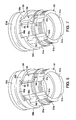
- Figure 6 is a perspective view of selected parts of the one-way clutch of the freewheel in accordance with the present invention, with the clutch pawls of the freewheel being maintained in their retracted or disengagement positions by the pawl-retracting mechanism;
- Figure 7 is a perspective view, similar to Figure 6, of selected parts of the one-way clutch of the freewheel in accordance with the present invention, but with the pawl-retracting mechanism moved to allowed the clutch pawls of the freewheel to move in their extended or engagement positions;
- Figure 8 is a perspective view of the pawl-retracting mechanism of the one-way clutch of the freewheel in accordance with the present invention.
- Figure 9 is another perspective view of the pawl-retracting mechanism of the one-way clutch of the freewheel in accordance with the present invention.
- Figure 10 is an enlarged, side elevational view of the pawl-retracting mechanism of the one-way clutch of the freewheel in accordance with the present invention.
- Figure 11 is an axial elevational view of the pawl-retracting mechanism of the one-way clutch of the freewheel in accordance with the present invention.
- Figure 12 is an enlarged side elevational view of one of the clutch pawls of the one-way clutch of the freewheel in accordance with the present invention.
- Figure 13 is a top plan view of one of the clutch pawls of the one-way clutch of the freewheel in accordance with the present invention.
- a bicycle 10 is illustrated that is equipped with a rear hub 12 in accordance with a first embodiment of the present invention.
- the bicycle 10 is arranged as a mountain bike.
- the bicycle 10 basically includes a front fork 14, a diamond-shaped frame 16, a handlebar 18, a drive unit 20, and a pair of front and rear wheels 21 and 22.
- the frame 16 has the front fork 14 movably coupled thereto.
- the handlebar 18 is fixedly coupled to the front fork 14 to turn the front wheel 21.
- the drive unit 20 basically comprises a chain CN, a pair of pedals PD, a front derailleur FD, a rear derailleur RD, a plurality of front sprockets FP, a plurality of rear sprockets RP and other conventional parts.
- the rear hub 12 is coupled to a center portion of the rear wheel 22.
- the rear hub 12 basically has a hub axle 30, a hub body or shell 31, a pair (first and second) of bearing assemblies 32a and 32b and a freewheel 33 in accordance with an embodiment of the present invention.
- the hub axle 30 is configured to be detachably mounted to a rearward portion of the frame 16 (see Figure 1).
- the hub body 31 is arranged around the outside circumference of the hub axle 30.
- the freewheel 33 is coupled to the right-hand end of the hub body 31 (when viewed as shown in Figure 2).
- the freewheel 33 has a rear sprocket cluster RP comprising, for example, ten sprockets mounted thereon such that the sprocket cluster RP can rotate as an integral unit with the freewheel 33.
- the first and second bearing assemblies 32a and 32b are arranged between the hub axle 30 and the hub body 31 and between the hub axle 30 and the freewheel 33.
- the hub axle 30 is a quick-release hub axle having a hollow axle main body 34 that has a right-hand (for example) external thread 34a arranged to span from a position slightly axially inward of the portion where the first bearing assembly 32a is installed to the axially outward end of the axle main body 34.
- the hollow axle main body 34 also has a right-hand external thread 34b that spans from a position slightly axially inward of the portion where the freewheel 33 is mounted to the axially outward end of the axle main body 34.
- the hub axle 30 also has a quick-release hub rod 34c, an adjustment nut 35 and a cam lever 36.
- the quick-release hub rod 34c is arranged so as to pass through the hollow axle main body 34.
- the adjustment nut 35 screws onto one end of the quick-release hub rod 34c.
- the cam lever 36 engages with the other end of the quick-release hub rod 34c.
- a first volute spring 36a is installed between one end (left-hand end in Figure 2) of the axle main body 34 and the cam lever 36.
- a second volute spring 36b is installed between the other end (right-hand end in Figure 2) of the axle main body 34 and the adjustment nut 35.
- the hub body 31 is a generally cylindrical member made of, for example, an aluminum alloy.
- the hub body 31 has a pair of hub flanges 31a and 31 b provided on both ends of the external circumference of the hub body 31.
- the hub flanges 31a and 31 b are configured for connecting spokes thereto.
- a bearing installation section 31 c is formed in one end face (left-hand end face in Figure 2) of the hub body 31.
- the bearing installation section 31c is configured to install the first bearing assembly 32a therein.
- the first bearing assembly 32a is a ball bearing that comprises a first outer race 37a, a first inner race 38a, and a plurality of spherical bodies (balls) 39a.
- the spherical bodies (balls) 39a are arranged between the two races 37a and 38a.
- the second bearing assembly 32b is a ball bearing that comprises a second outer race 37b, a second inner race 38b, and a plurality of spherical bodies (balls) 39b.
- the spherical bodies (balls) 39b are arranged between the two races 37b and 38b.
- Each set of spherical balls 39a and 39b is held by a retainer (not shown) such that adjacent balls of each set maintain a prescribed circumferential spacing therebetween.
- the first outer race 37a is press fitted into the bearing installation section 31c formed in the hub body 31.
- the second outer race 37b is screwed onto the freewheel 33.
- the first and second inner races 38a and 38b are both screwed onto externally threaded sections 34a and 34b, respectively, that are formed on the axle main body 34 of the hub axle 30 and function as ball pushing members used to adjust the amount of axial play in the bearing assemblies 32a and 32b.
- Lock nuts 50a and 50b are arranged so as to contact the axially outward facing sides of the first and second inner races 38a and 38b, respectively, and serve to prevent the first and second inner races 38a and 38b from rotating and moving in the axial direction.
- the freewheel 33 basically includes an inner tubular member 51, an outer tubular member 52, a pair of bearing assemblies 53a and 53b, a pair of clutch pawls 54, a pair of biasing members 55 and a pawl-retracting member 56.
- the inner tubular member 51 is configured to be fixedly coupled to the hub body 31.
- the outer tubular member 52 is arranged around the outside circumference of the inner tubular member 51.
- the bearing assemblies 53a and 53b are arranged between the inner tubular member 51 and the outer tubular member 52 and configured to couple the outer tubular member 52 to the inner tubular member 51 such that the outer tubular member 52 can rotate freely with respect to the inner tubular member 51.
- the clutch pawls 54 are configured to transfer forward rotation of the outer tubular member 52 (i.e., rotation corresponding to forward movement of the bicycle) to the inner tubular member 51 and not transfer rearward rotation of the outer tubular member 52 to the inner tubular member 51.
- the pawl-retracting member 56 is disposed between the inner tubular member 51 and the outer tubular member 52.
- the pawl-retracting member 56 is frictionally engaged with the internal circumferential surface of the outer tubular member 52 to rotate with the outer tubular member 52 between a pawl-retracting position in which the pawl-retracting member 56 maintains the clutch pawls 54 in their disengagement positions ( Figure 4) and a pawl-releasing position in which the pawl-retracting member 56 releases the clutch pawls 54 to move to their engagement positions ( Figure 5).
- the pawl-retracting member 56 is an annular member that includes an annular or arcuate base portion 56a, a pair of pawl-interacting portions 56b and a pair of movement-restricting portions 56c.
- the pawl-interacting portions 56b extend axially from the annular base 56a.
- the movement-restricting portions 56c extend inwardly from at least one of the base portion 56a and the pawl-interacting portion 56b in a radial direction.
- the pawl-retracting member 56 is a one-piece, unitary member made of non-metallic material such as resin material.
- the base portion 56a is at least an arcuate member that curves around the outer side circumference of the inner tubular member 51.
- the base portion 56a is ring shaped member that encircles the inner tubular member 51.
- the inner diameter of the base portion 56a is slightly larger that the outer side circumference of the inner tubular member 51 so that a very small gap exist therebetween.
- the outer diameter of the base portion 56a is frictionally contacting the inner side circumference of the outer tubular member 52 so that movement the outer tubular member 52 causes the pawl-retracting member 56 to move therewith until the movement-restricting portions 56c contact the inner tubular member 51 as explained below.
- the clutch pawls 54 are retracted by the rotational movement of the pawl-retracting member 56.
- the pawl-interacting portions 56b holds down the clutch pawls 54 when the pawl-retracting member 56 rotates to its pawl-retracting position.
- the pawl-retracting member 56 is rotated by friction exerted between the outer surface of the pawl-retracting member 56 and the inner surface of the outer tubular member 52 of the freewheel 33.
- Each of the movement-restricting portions 56c includes a pair of abutments that selectively contact the inner tubular member 51 to limit rotational movement therebetween.
- the movement-restricting portions 56c are configured and arranged to selectively contact the inner tubular member 51 to restrict the rotational movement of the pawl-retracting member 56.
- the inner tubular member 51 is a step-shaped cylindrical member made of chromium-molybdenum steel or other comparatively high-strength steel material.
- the inner tubular member 51 is non-rotatably coupled with respect to the hub body 31 by a cylindrical coupling member 58 having serrations 58a formed on the external circumferential surface thereof.
- the serrations 58a of the coupling member 58 are configured to mesh with serrations 31d provided on an internal surface of the right-hand end of the hub body 31, and with serrations 51a provided on an internal surface of a larger diameter section of the left-hand end of the inner tubular member 51 (i.e., left-hand end as viewed in Figure 3).
- the inner tubular member 51 is fastened to the hub body 31 with a cylindrical bolt 59 configured pass through the insides of the inner tubular member 51 and the coupling member 58 and screw into the internal surface of the hub body 31.
- the inner tubular member 51 further includes a bearing installation section 51b, a plurality of clutch pawl installation recesses 51c, and a ball pushing surface 51d.
- the bearing installation section 51b includes threads formed on the external circumferential surface of the right-hand end of the inner tubular member 51 (i.e., the right-hand end when viewed as shown in Figure 3) for installing the second bearing assembly 32b.
- the clutch pawl installation recesses 51 c are formed around a portion of the external circumferential surface of the inner tubular member 51 located further inward in the axial direction than the bearing installation section 51b.
- the clutch pawl installation recesses 51c are arranged so as to be spaced apart from one another along a circumferential direction.
- Two of the clutch pawl installation recesses 51c are configured such that the clutch pawls 54 (described later) can be pivotally mounted therein.
- the other two pawl installation recesses 51c receive the movement-restricting portions 56c of the pawl-retracting member 56 to limit rotational movement of the pawl-retracting member 56 relative to the inner tubular member 51.
- the ball pushing surface 51d is formed on the external circumferential surface of the larger diameter portion of the inner tubular member 51 (i.e., left-hand end from the perspective of Figure 3).
- the ball pushing surface 51d constitutes the inner race of a third bearing assembly 53a.
- Two spring arrangement grooves 51e are also formed in the external circumferential surface of the inner tubular member 51.
- the two spring arrangement grooves 51e are configured to run in the circumferential direction and arranged so as to be spaced apart from each other in the axial direction. Both of the spring arrangement grooves 51e are arranged to cross through the clutch pawl installation recesses 51 c.
- each of the clutch pawl installation recesses 51c comprises two circular arc-shaped recessed sections, one larger and one smaller, that are joined together. The smaller recessed sections are where the clutch pawls 54 are attached.
- Each of the clutch pawl installation recesses 51c has a pair of stop surfaces that are selectively contacted by the movement-restricting portion 56c of the pawl-retracting member 56 to limit rotational movement therebetween.
- the movement-restricting portions 56c are positioned in two of the clutch pawl installation recesses 51c of the inner tubular member 51 to prevent the pawl-retracting member 56 from rotating too much.
- the outer tubular member 52 is arranged around an outer side circumference of the inner tubular member 51, with an internal circumferential surface of the outer tubular member 52 having a plurality of ratchet teeth 52a.
- the outer tubular member 52 has a sprocket mounting part 52b formed on an external circumferential surface of the outer tubular member 52.
- the sprocket mounting part 52b is configured to mount the rear sprocket cluster RP such that the rear sprocket cluster RP rotates as an integral unit with the outer tubular member 52.
- the clutch pawls 54 are positioned radially inwardly from the sprocket mounting part 52b.
- the outer tubular member 52 is supported in a freely rotatable manner on the external circumference of the inner tubular member 51.
- the sprocket mounting part 52b comprises, for example, nine protrusions with one of the protrusions having a smaller width (i.e., dimension in the circumferential direction) than the other protrusions.
- the ratchet teeth 52a are arranged on the portion of the internal surface of the outer tubular member 52 that is located between the bearing assemblies 53a and 53b.
- the ratchet teeth 52a are arranged so as to be spaced apart from one another along a circumferential direction.
- the outer tubular member 52 is supported in a freely rotatable manner on the inner tubular member 51 by the bearing assemblies 53a and 53b.
- the ball bearing surfaces 52c and 52d are formed on the internal circumferential surface of the outer tubular member 52, and arranged so as to be spaced apart from each other in the axial direction.
- the ball bearing surfaces 52c and 52d serve as the outer races for the bearing assemblies 53a and 53b, respectively.
- the ratchet teeth 52a are provided axially between the ball bearing surfaces 52c and 52d.
- the clutch pawls 54 are disposed on the outer side circumference of the inner tubular member 51 and freely movable between an engagement position in which the clutch pawls 54 engages the ratchet teeth 52a and a disengagement position in which the clutch pawls 54 are disengaged from the ratchet teeth 52a.
- the biasing members 55 apply an urging force to the clutch pawls 54 to urge the clutch pawls 54 toward their engagement positions.
- the bearing assemblies 53a and 53b are arranged between the inner tubular member 51 and the outer tubular member 52 and serve to mount the outer tubular member 52 onto the inner tubular member 51 such that the outer tubular member 52 can rotate freely with respect to the inner tubular member 51.
- the bearing assembly 53a is a ball bearing that comprises the ball bearing surface 52c, the ball pushing surface 51d and a plurality of spherical bodies (balls) 60.
- the ball bearing surface 52c is formed on the internal circumferential surface of the outer tubular member 52 and serves as an outer race of the bearing assembly 53a.
- the ball pushing surface 51d is formed on the external circumferential surface of the inner tubular member 51 and serves as an inner race of the bearing assembly 53a.
- the spherical bodies (balls) 60 are arranged between the ball bearing surface 52c and the ball pushing surface 51d.
- the bearing assembly 53b is a ball bearing that comprises the ball bearing surface 52d, a ball pushing surface 62 of the second outer race 37b and a plurality of spherical bodies (balls) 61.
- the ball bearing surface 52d is formed on the internal circumferential surface of the outer tubular member 52 and serves as an outer race of the bearing assembly 53b.
- the ball pushing surface 62 is formed on the external circumferential surface of the outer race 37b of the second bearing assembly 32b and serves as an inner race of the bearing assembly 53b.
- the spherical bodies (balls) 61 are arranged between the ball bearing surface 52d and the ball pushing surface 62 of the second outer race 37b. Each set of spherical balls 60 and 61 is held by a retainer (not shown) such that adjacent balls of each set maintain a prescribed circumferential spacing therebetween.
- the ratchet teeth 52a, the pawl clutches 54, the biasing members 55 and the pawl-retracting member 56 form a one-way clutch that serves to transfer only forward rotation of the outer tubular member 52 to the inner tubular member 51.
- the ratchet teeth 52a are provided on the internal circumferential surface of the outer tubular member 52.
- the clutch pawls 54 are arranged on the external circumferential surface of the inner tubular member 51 in such a manner as to be spaced apart from each other along a circumferential direction.
- the biasing members 55 are C-shaped spring members that are configured and arranged to apply an urging force against the clutch pawls 54 in a radial inward direction.
- the biasing members 55 constitute a force applying member.
- the one-way clutch is provided for the purpose of transferring rotation from the outer tubular member 52 to the inner tubular member 51 only when the outer tubular member 52 rotates in the forward direction in Figure 4 (i.e., the clockwise direction in Figure 5).
- the outer tubular member 52 and the pawl-retracting member 56 rotate together such that the clutch pawls 54 are uncovered by the pawl-interacting portions 56b to allow the clutch pawls 54 to move to their engagement positions due to the urging force of the biasing members 55.
- Rotational movement of the pawl-retracting member 56 is limited by the movement-restricting portions 56c contacting one of the end stops of the clutch pawl installation recesses 51 c.
- the clutch pawls 54 will move beneath the pawl-interacting portions 56b to retract the clutch pawls 54.
- the pawl-retracting member 56 will rotate with the inner tubular member 51 such that the rotation of the inner tubular member 51 will not be transferred to the outer tubular member 52.
- each of the clutch pawls 54 is mounted in one of the clutch pawl installation recesses 51c of the inner tubular member 51 in such a fashion that it can pivot freely between an engagement position where it engages with one of the ratchet teeth 52a and the disengagement position where it does not engage with the ratchet teeth 52a.
- torque can be transferred from the outer tubular member 52 to the inner tubular member 51.
- each of the clutch pawls 54 has a claw-like part 63 and a spring engaging part 64.
- the spring engaging part 64 is formed integrally on one side (left side in Figure 13) for one of the clutch pawls 54 as shown in solid lines in Figure 13, and formed integrally on the other side (right side in Figure 13) for the other one of clutch pawls 54 as shown in broken lines in Figure 13.
- a base end portion of the claw-like part 63 and the spring engaging part 64 are shaped like a circular arc that is configured to be mounted in one of the clutch pawl installation recesses 51c in such a fashion that the clutch pawl 54 can pivot freely.
- the claw-like parts 63 has a tip end section 63a configured to abut (selectively mesh with) against one of the ratchet teeth 52a.
- a spring engaging groove 64a is formed in the spring engaging part 64.
- the spring engaging grooves 64a are configured to engage one of the biasing members 55.
- one of the biasing members 55 acts on one of the clutch pawls 54 and the other one of the biasing members 55 acts on the other one of the clutch pawls 54.
- the spring engaging groove 64a is angled relative to the claw-like part 63. This configuration enables the clutch pawl 54 to stand up in the engagement position when one of the biasing members 55 engages the spring engaging groove 64a.
- the spring engaging groove 64a is configured such that it can be aligned with one or the other of the two spring arrangement grooves 51e along the circumferential direction when the clutch pawl 54 is mounted in the clutch pawl installation recess 51c.
- each of the biasing members 55 is made of a metal elastic wire-like material that has been bent into a C-shape such that it can be installed in one of the circular spring arrangement grooves 51e. Consequently, each of the biasing members 55 has an open end part and is thus shaped like a circle from which one small section has been cut out (i.e., a split ring).
- the biasing members 55 can be prevented from rotating and the open end parts can be prevented from being arranged at one of the clutch pawls 54.
- the biasing members 55 are curved such that the internal diameters thereof are the same or smaller than the external diameters of the bottom surfaces of the spring arrangement grooves 51e.
- the term “configured” as used herein to describe a component, section or part of a device includes hardware and/or software that is constructed and/or programmed to carry out the desired function.
- the term “comprising” and its derivatives, as used herein are intended to be open ended terms that specify the presence of the stated features, elements, components, groups, integers, and/or steps, but do not exclude the presence of other unstated features, elements, components, groups, integers and/or steps.
- the foregoing also applies to words having similar meanings such as the terms, “including”, “having” and their derivatives.
- the terms "part,” “section,” “portion,” “member” or “element” when used in the singular can have the dual meaning of a single part or a plurality of parts.
- the following directional terms “forward, rearward, above, downward, vertical, horizontal, below and transverse” as well as any other similar directional terms refer to those directions of a bicycle equipped with the present invention. Accordingly, these terms, as utilized to describe the present invention should be interpreted relative to a bicycle equipped with the present invention as used in the normal riding position.
- terms of degree such as “substantially”, “about” and “approximately” as used herein mean a reasonable amount of deviation of the modified term such that the end result is not significantly changed. For example, these terms can be construed as including a deviation of at least ⁇ 5% of the modified term if this deviation would not negate the meaning of the word it modifies.
Landscapes
- Engineering & Computer Science (AREA)
- Mechanical Engineering (AREA)
- General Engineering & Computer Science (AREA)
- Mechanical Operated Clutches (AREA)
Abstract
Description
- This invention generally relates to a bicycle freewheel to be mounted to a hub of a bicycle. More specifically, the present invention relates to a bicycle freewheel having a pawl-retracting mechanism.
- Bicycling is becoming an increasingly more popular form of recreation as well as a means of transportation. Moreover, bicycling has become a very popular competitive sport for both amateurs and professionals. Whether the bicycle is used for recreation, transportation or competition, the bicycle industry is constantly improving the various components of the bicycle. The bicycle drive train has been extensively redesigned.
- In many bicycles with multiple speeds, a wheel of the bicycle, typically the rear wheel, is provided with a hub having a gear changing mechanism or the like. Often the hub is provided with a freewheel that is arranged either as an integral part of the hub body or as a separate member. The freewheel usually has a one-way clutch function whereby it only transfers torque in one direction. One well-known conventional type of freewheel is provided with a pawl-type one-way clutch that includes ratchet teeth and a plurality of clutch pawls configured to selectively mesh with the ratchet teeth. In pawl-type one-way clutches, the clutch pawls are forced (spring loaded) toward engagement positions where they mesh with the ratchet teeth. Two examples of this type of freewheel are disclosed in
U.S. Patent No. 6,202,813 andU.S. Patent No. 6,533,700 , which are assigned to Shimano, Inc. The freewheels of these patents have a pawl retracting mechanism for moving the clutch pawls to disengagement positions. These freewheels work quite well. However, the pawl-retracting mechanism of theU.S. Patent No. 6,202,813 requires a slide spring to move a pawl pressure component and the pawl-retracting mechanism inU.S. Patent No. 6,533,700 must be actuated in response to shift operation. Therefore, these pawl-retracting mechanisms have a complex structure. - In view of the above, it will be apparent to those skilled in the art from this disclosure that there exists a need for an improved bicycle freewheel. This invention addresses this need in the art as well as other needs, which will become apparent to those skilled in the art from this disclosure.
- One object of the present invention is to provide a freewheel with a pawl-retracting mechanism that is simple and inexpensive to manufacture and assemble.
- In accordance with one aspect of the present invention, the foregoing object can basically be attained by providing a bicycle freewheel that basically comprises an inner tubular member, an outer tubular member, at least one bearing assembly, a clutch pawl, a biasing member and a pawl-retracting member. The inner tubular member is configured to be coupled to a bicycle hub. The outer tubular member is arranged around an outer side circumference of the inner tubular member, with an internal circumferential surface of the outer tubular member having a plurality of ratchet teeth. The bearing assembly is disposed between the inner tubular member and the outer tubular member to rotatably couple the outer tubular member to the inner tubular member such that the outer tubular member rotates freely with respect to the inner tubular member. The clutch pawl is disposed on the outer side circumference of the inner tubular member and freely movable between an engagement position in which the clutch pawl engages the ratchet teeth and a disengagement position in which the clutch pawl is disengaged from the ratchet teeth. The biasing member applies an urging force to the clutch pawl to urge the clutch pawl toward the engagement position. The pawl-retracting member is disposed between the inner tubular member and the outer tubular member with the pawl-retracting member frictionally engaged with the internal circumferential surface of the outer tubular member to rotate with the outer tubular member between a pawl-retracting position in which the pawl-retracting member maintains the clutch pawl in the disengagement position and a pawl-releasing position in which the pawl-retracting member releases the clutch pawl to move to the engagement position.
- Accordingly with this invention, because the pawl-retracting member is rotated by friction exerted between the pawl-retracting member and the outer tubular member of the freewheel, no complex structure is required to retract the clutch pawls. Thus, with this arrangement, improved wheel-rotation efficiency (because of reduction of friction between clutch pawls and ratchet teeth) and reduction of pawl noise are achieved inexpensively.
- These and other objects, features, aspects and advantages of the present invention will become apparent to those skilled in the art from the following detailed description, which, taken in conjunction with the annexed drawings, discloses a preferred embodiment of the present invention.
- Referring now to the attached drawings which form a part of this original disclosure:
- Figure 1 is a side elevational view of a bicycle that is equipped with a rear hub that includes a freewheel in accordance with one embodiment of the present invention;
- Figure 2 is a half-cross sectional view of the rear hub on which the freewheel is installed in accordance with the present invention;
- Figure 3 is an enlarged half-cross sectional view of the freewheel portion of the rear hub illustrated in Figure 2 in accordance with the present invention;
- Figure 4 is a transverse cross sectional view of the one-way clutch of the freewheel in accordance with the present invention, as seen along section line 4-4 of Figure 3 with the clutch pawls of the freewheel being maintained in their retracted or disengagement positions by the pawl-retracting mechanism;
- Figure 5 is a transverse cross sectional view, similar to Figure 4, of the one-way clutch of the freewheel in accordance with the present invention, but with the pawl-retracting mechanism moved to allowed the clutch pawls of the freewheel to move in their extended or engagement positions;
- Figure 6 is a perspective view of selected parts of the one-way clutch of the freewheel in accordance with the present invention, with the clutch pawls of the freewheel being maintained in their retracted or disengagement positions by the pawl-retracting mechanism;
- Figure 7 is a perspective view, similar to Figure 6, of selected parts of the one-way clutch of the freewheel in accordance with the present invention, but with the pawl-retracting mechanism moved to allowed the clutch pawls of the freewheel to move in their extended or engagement positions;
- Figure 8 is a perspective view of the pawl-retracting mechanism of the one-way clutch of the freewheel in accordance with the present invention;
- Figure 9 is another perspective view of the pawl-retracting mechanism of the one-way clutch of the freewheel in accordance with the present invention;
- Figure 10 is an enlarged, side elevational view of the pawl-retracting mechanism of the one-way clutch of the freewheel in accordance with the present invention;
- Figure 11 is an axial elevational view of the pawl-retracting mechanism of the one-way clutch of the freewheel in accordance with the present invention;
- Figure 12 is an enlarged side elevational view of one of the clutch pawls of the one-way clutch of the freewheel in accordance with the present invention; and
- Figure 13 is a top plan view of one of the clutch pawls of the one-way clutch of the freewheel in accordance with the present invention.
- Selected embodiments of the present invention will now be explained with reference to the drawings. It will be apparent to those skilled in the art from this disclosure that the following descriptions of the embodiments of the present invention are provided for illustration only and not for the purpose of limiting the invention as defined by the appended claims and their equivalents.
- Referring initially to Figure 1, a
bicycle 10 is illustrated that is equipped with arear hub 12 in accordance with a first embodiment of the present invention. As seen in Figure 1, thebicycle 10 is arranged as a mountain bike. Thebicycle 10 basically includes afront fork 14, a diamond-shaped frame 16, ahandlebar 18, adrive unit 20, and a pair of front andrear wheels frame 16 has thefront fork 14 movably coupled thereto. Thehandlebar 18 is fixedly coupled to thefront fork 14 to turn thefront wheel 21. Thedrive unit 20 basically comprises a chain CN, a pair of pedals PD, a front derailleur FD, a rear derailleur RD, a plurality of front sprockets FP, a plurality of rear sprockets RP and other conventional parts. Therear hub 12 is coupled to a center portion of therear wheel 22. - As shown in Figure 2, the
rear hub 12 basically has ahub axle 30, a hub body orshell 31, a pair (first and second) ofbearing assemblies freewheel 33 in accordance with an embodiment of the present invention. Thehub axle 30 is configured to be detachably mounted to a rearward portion of the frame 16 (see Figure 1). Thehub body 31 is arranged around the outside circumference of thehub axle 30. Thefreewheel 33 is coupled to the right-hand end of the hub body 31 (when viewed as shown in Figure 2). Thefreewheel 33 has a rear sprocket cluster RP comprising, for example, ten sprockets mounted thereon such that the sprocket cluster RP can rotate as an integral unit with thefreewheel 33. The first and second bearingassemblies hub axle 30 and thehub body 31 and between thehub axle 30 and thefreewheel 33. - The
hub axle 30 is a quick-release hub axle having a hollow axlemain body 34 that has a right-hand (for example)external thread 34a arranged to span from a position slightly axially inward of the portion where thefirst bearing assembly 32a is installed to the axially outward end of the axlemain body 34. The hollow axlemain body 34 also has a right-handexternal thread 34b that spans from a position slightly axially inward of the portion where thefreewheel 33 is mounted to the axially outward end of the axlemain body 34. Thehub axle 30 also has a quick-release hub rod 34c, anadjustment nut 35 and acam lever 36. The quick-release hub rod 34c is arranged so as to pass through the hollow axlemain body 34. Theadjustment nut 35 screws onto one end of the quick-release hub rod 34c. Thecam lever 36 engages with the other end of the quick-release hub rod 34c. Afirst volute spring 36a is installed between one end (left-hand end in Figure 2) of the axlemain body 34 and thecam lever 36. Asecond volute spring 36b is installed between the other end (right-hand end in Figure 2) of the axlemain body 34 and theadjustment nut 35. - The
hub body 31 is a generally cylindrical member made of, for example, an aluminum alloy. Thehub body 31 has a pair ofhub flanges hub body 31. Thehub flanges installation section 31 c is formed in one end face (left-hand end face in Figure 2) of thehub body 31. The bearinginstallation section 31c is configured to install thefirst bearing assembly 32a therein. - The
first bearing assembly 32a is a ball bearing that comprises a firstouter race 37a, a firstinner race 38a, and a plurality of spherical bodies (balls) 39a. The spherical bodies (balls) 39a are arranged between the tworaces second bearing assembly 32b is a ball bearing that comprises a secondouter race 37b, a secondinner race 38b, and a plurality of spherical bodies (balls) 39b. The spherical bodies (balls) 39b are arranged between the tworaces spherical balls - The first
outer race 37a is press fitted into thebearing installation section 31c formed in thehub body 31. The secondouter race 37b is screwed onto thefreewheel 33. The first and secondinner races sections main body 34 of thehub axle 30 and function as ball pushing members used to adjust the amount of axial play in thebearing assemblies inner races inner races - As shown in Figure 3, the
freewheel 33 basically includes aninner tubular member 51, anouter tubular member 52, a pair of bearingassemblies clutch pawls 54, a pair of biasingmembers 55 and a pawl-retractingmember 56. Theinner tubular member 51 is configured to be fixedly coupled to thehub body 31. The outertubular member 52 is arranged around the outside circumference of theinner tubular member 51. Thebearing assemblies inner tubular member 51 and the outertubular member 52 and configured to couple the outertubular member 52 to theinner tubular member 51 such that the outertubular member 52 can rotate freely with respect to theinner tubular member 51. Theclutch pawls 54 are configured to transfer forward rotation of the outer tubular member 52 (i.e., rotation corresponding to forward movement of the bicycle) to theinner tubular member 51 and not transfer rearward rotation of the outertubular member 52 to theinner tubular member 51. - As shown in Figures 4 to 5, the pawl-retracting
member 56 is disposed between theinner tubular member 51 and the outertubular member 52. The pawl-retractingmember 56 is frictionally engaged with the internal circumferential surface of the outertubular member 52 to rotate with the outertubular member 52 between a pawl-retracting position in which the pawl-retractingmember 56 maintains theclutch pawls 54 in their disengagement positions (Figure 4) and a pawl-releasing position in which the pawl-retractingmember 56 releases theclutch pawls 54 to move to their engagement positions (Figure 5). - As shown in Figures 8 to 11, the pawl-retracting
member 56 is an annular member that includes an annular orarcuate base portion 56a, a pair of pawl-interactingportions 56b and a pair of movement-restrictingportions 56c. The pawl-interactingportions 56b extend axially from theannular base 56a. The movement-restrictingportions 56c extend inwardly from at least one of thebase portion 56a and the pawl-interactingportion 56b in a radial direction. Preferably, the pawl-retractingmember 56 is a one-piece, unitary member made of non-metallic material such as resin material. - The
base portion 56a is at least an arcuate member that curves around the outer side circumference of theinner tubular member 51. In the illustrated embodiment, thebase portion 56a is ring shaped member that encircles theinner tubular member 51. The inner diameter of thebase portion 56a is slightly larger that the outer side circumference of theinner tubular member 51 so that a very small gap exist therebetween. The outer diameter of thebase portion 56a is frictionally contacting the inner side circumference of the outertubular member 52 so that movement the outertubular member 52 causes the pawl-retractingmember 56 to move therewith until the movement-restrictingportions 56c contact theinner tubular member 51 as explained below. - The
clutch pawls 54 are retracted by the rotational movement of the pawl-retractingmember 56. In particular, the pawl-interactingportions 56b holds down theclutch pawls 54 when the pawl-retractingmember 56 rotates to its pawl-retracting position. In such a structure mentioned above, the pawl-retractingmember 56 is rotated by friction exerted between the outer surface of the pawl-retractingmember 56 and the inner surface of the outertubular member 52 of thefreewheel 33. - Each of the movement-restricting
portions 56c includes a pair of abutments that selectively contact theinner tubular member 51 to limit rotational movement therebetween. Thus, the movement-restrictingportions 56c are configured and arranged to selectively contact theinner tubular member 51 to restrict the rotational movement of the pawl-retractingmember 56. - The
inner tubular member 51 is a step-shaped cylindrical member made of chromium-molybdenum steel or other comparatively high-strength steel material. Theinner tubular member 51 is non-rotatably coupled with respect to thehub body 31 by acylindrical coupling member 58 havingserrations 58a formed on the external circumferential surface thereof. Theserrations 58a of thecoupling member 58 are configured to mesh withserrations 31d provided on an internal surface of the right-hand end of thehub body 31, and withserrations 51a provided on an internal surface of a larger diameter section of the left-hand end of the inner tubular member 51 (i.e., left-hand end as viewed in Figure 3). Theinner tubular member 51 is fastened to thehub body 31 with acylindrical bolt 59 configured pass through the insides of theinner tubular member 51 and thecoupling member 58 and screw into the internal surface of thehub body 31. - The
inner tubular member 51 further includes abearing installation section 51b, a plurality of clutch pawl installation recesses 51c, and aball pushing surface 51d. The bearinginstallation section 51b includes threads formed on the external circumferential surface of the right-hand end of the inner tubular member 51 (i.e., the right-hand end when viewed as shown in Figure 3) for installing thesecond bearing assembly 32b. The clutch pawl installation recesses 51 c are formed around a portion of the external circumferential surface of theinner tubular member 51 located further inward in the axial direction than the bearinginstallation section 51b. The clutch pawl installation recesses 51c are arranged so as to be spaced apart from one another along a circumferential direction. Two of the clutch pawl installation recesses 51c are configured such that the clutch pawls 54 (described later) can be pivotally mounted therein. The other two pawl installation recesses 51c receive the movement-restrictingportions 56c of the pawl-retractingmember 56 to limit rotational movement of the pawl-retractingmember 56 relative to theinner tubular member 51. Theball pushing surface 51d is formed on the external circumferential surface of the larger diameter portion of the inner tubular member 51 (i.e., left-hand end from the perspective of Figure 3). Theball pushing surface 51d constitutes the inner race of athird bearing assembly 53a. Thus, the inner the left-hand end of theinner tubular member 51 supports the outertubular member 52 in a freely rotatable manner. - Two
spring arrangement grooves 51e (only one shown in Figures 6 and 7) are also formed in the external circumferential surface of theinner tubular member 51. The twospring arrangement grooves 51e are configured to run in the circumferential direction and arranged so as to be spaced apart from each other in the axial direction. Both of thespring arrangement grooves 51e are arranged to cross through the clutch pawl installation recesses 51 c. - As shown in Figures 6 and 7, each of the clutch
pawl installation recesses 51c comprises two circular arc-shaped recessed sections, one larger and one smaller, that are joined together. The smaller recessed sections are where theclutch pawls 54 are attached. Each of the clutchpawl installation recesses 51c has a pair of stop surfaces that are selectively contacted by the movement-restrictingportion 56c of the pawl-retractingmember 56 to limit rotational movement therebetween. In particular, the movement-restrictingportions 56c are positioned in two of the clutch pawl installation recesses 51c of theinner tubular member 51 to prevent the pawl-retractingmember 56 from rotating too much. - As shown in Figures 4 and 5, the outer
tubular member 52 is arranged around an outer side circumference of theinner tubular member 51, with an internal circumferential surface of the outertubular member 52 having a plurality ofratchet teeth 52a. The outertubular member 52 has asprocket mounting part 52b formed on an external circumferential surface of the outertubular member 52. Thesprocket mounting part 52b is configured to mount the rear sprocket cluster RP such that the rear sprocket cluster RP rotates as an integral unit with the outertubular member 52. Theclutch pawls 54 are positioned radially inwardly from thesprocket mounting part 52b. The outertubular member 52 is supported in a freely rotatable manner on the external circumference of theinner tubular member 51. As shown in Figures 4 and 5, thesprocket mounting part 52b comprises, for example, nine protrusions with one of the protrusions having a smaller width (i.e., dimension in the circumferential direction) than the other protrusions. - The
ratchet teeth 52a are arranged on the portion of the internal surface of the outertubular member 52 that is located between the bearingassemblies ratchet teeth 52a are arranged so as to be spaced apart from one another along a circumferential direction. In the embodiment shown in Figures 4 and 5, for example, there are eighteen of theratchet teeth 52a with each of theratchet teeth 52a being shaped like a saw tooth that is asymmetrical in the circumferential direction. - As shown in Figure 3, the outer
tubular member 52 is supported in a freely rotatable manner on theinner tubular member 51 by thebearing assemblies tubular member 52, and arranged so as to be spaced apart from each other in the axial direction. The ball bearing surfaces 52c and 52d serve as the outer races for thebearing assemblies ratchet teeth 52a are provided axially between the ball bearing surfaces 52c and 52d. Thus, theclutch pawls 54 are disposed on the outer side circumference of theinner tubular member 51 and freely movable between an engagement position in which theclutch pawls 54 engages theratchet teeth 52a and a disengagement position in which theclutch pawls 54 are disengaged from theratchet teeth 52a. The biasingmembers 55 apply an urging force to theclutch pawls 54 to urge theclutch pawls 54 toward their engagement positions. - The
bearing assemblies inner tubular member 51 and the outertubular member 52 and serve to mount the outertubular member 52 onto theinner tubular member 51 such that the outertubular member 52 can rotate freely with respect to theinner tubular member 51. The bearingassembly 53a is a ball bearing that comprises theball bearing surface 52c, theball pushing surface 51d and a plurality of spherical bodies (balls) 60. Theball bearing surface 52c is formed on the internal circumferential surface of the outertubular member 52 and serves as an outer race of the bearingassembly 53a. Theball pushing surface 51d is formed on the external circumferential surface of theinner tubular member 51 and serves as an inner race of the bearingassembly 53a. The spherical bodies (balls) 60 are arranged between theball bearing surface 52c and theball pushing surface 51d. Likewise, the bearingassembly 53b is a ball bearing that comprises theball bearing surface 52d, aball pushing surface 62 of the secondouter race 37b and a plurality of spherical bodies (balls) 61. Theball bearing surface 52d is formed on the internal circumferential surface of the outertubular member 52 and serves as an outer race of the bearingassembly 53b. Theball pushing surface 62 is formed on the external circumferential surface of theouter race 37b of thesecond bearing assembly 32b and serves as an inner race of the bearingassembly 53b. The spherical bodies (balls) 61 are arranged between theball bearing surface 52d and theball pushing surface 62 of the secondouter race 37b. Each set ofspherical balls - As shown in Figures 4 and 5, the
ratchet teeth 52a, thepawl clutches 54, the biasingmembers 55 and the pawl-retractingmember 56 form a one-way clutch that serves to transfer only forward rotation of the outertubular member 52 to theinner tubular member 51. Theratchet teeth 52a are provided on the internal circumferential surface of the outertubular member 52. Theclutch pawls 54 are arranged on the external circumferential surface of theinner tubular member 51 in such a manner as to be spaced apart from each other along a circumferential direction. The biasingmembers 55 are C-shaped spring members that are configured and arranged to apply an urging force against theclutch pawls 54 in a radial inward direction. Thus, the biasingmembers 55 constitute a force applying member. - The one-way clutch is provided for the purpose of transferring rotation from the outer
tubular member 52 to theinner tubular member 51 only when the outertubular member 52 rotates in the forward direction in Figure 4 (i.e., the clockwise direction in Figure 5). In other words, when the outertubular member 52 rotates in the forward direction in Figure 4, the outertubular member 52 and the pawl-retractingmember 56 rotate together such that theclutch pawls 54 are uncovered by the pawl-interactingportions 56b to allow theclutch pawls 54 to move to their engagement positions due to the urging force of the biasingmembers 55. Rotational movement of the pawl-retractingmember 56 is limited by the movement-restrictingportions 56c contacting one of the end stops of the clutch pawl installation recesses 51 c. However, if theinner tubular member 51 rotates in the clockwise direction (i.e., the clockwise direction from the perspective of Figures 4 and 5) relative to the outertubular member 52, theclutch pawls 54 will move beneath the pawl-interactingportions 56b to retract theclutch pawls 54. Once the end stops of the clutch pawl installation recesses 51c contact the movement-restrictingportions 56c, the pawl-retractingmember 56 will rotate with theinner tubular member 51 such that the rotation of theinner tubular member 51 will not be transferred to the outertubular member 52. - In this embodiment, there are two of the
clutch pawls 54 arranged to be spaced apart from one another along a circumferential direction. Each of theclutch pawls 54 is mounted in one of the clutch pawl installation recesses 51c of theinner tubular member 51 in such a fashion that it can pivot freely between an engagement position where it engages with one of theratchet teeth 52a and the disengagement position where it does not engage with theratchet teeth 52a. When theclutch pawls 54 are in the engagement position, torque can be transferred from the outertubular member 52 to theinner tubular member 51. - As shown in Figures 12 and 13, the
clutch pawls 54 are mirror images of each other. Thus, each of theclutch pawls 54 has a claw-like part 63 and aspring engaging part 64. Thespring engaging part 64 is formed integrally on one side (left side in Figure 13) for one of theclutch pawls 54 as shown in solid lines in Figure 13, and formed integrally on the other side (right side in Figure 13) for the other one ofclutch pawls 54 as shown in broken lines in Figure 13. A base end portion of the claw-like part 63 and thespring engaging part 64 are shaped like a circular arc that is configured to be mounted in one of the clutch pawl installation recesses 51c in such a fashion that theclutch pawl 54 can pivot freely. The claw-like parts 63 has atip end section 63a configured to abut (selectively mesh with) against one of theratchet teeth 52a. Aspring engaging groove 64a is formed in thespring engaging part 64. Thespring engaging grooves 64a are configured to engage one of the biasingmembers 55. Thus, one of the biasingmembers 55 acts on one of theclutch pawls 54 and the other one of the biasingmembers 55 acts on the other one of theclutch pawls 54. Thespring engaging groove 64a is angled relative to the claw-like part 63. This configuration enables theclutch pawl 54 to stand up in the engagement position when one of the biasingmembers 55 engages thespring engaging groove 64a. Thespring engaging groove 64a is configured such that it can be aligned with one or the other of the twospring arrangement grooves 51e along the circumferential direction when theclutch pawl 54 is mounted in the clutchpawl installation recess 51c. - In this embodiment, each of the biasing
members 55 is made of a metal elastic wire-like material that has been bent into a C-shape such that it can be installed in one of the circularspring arrangement grooves 51e. Consequently, each of the biasingmembers 55 has an open end part and is thus shaped like a circle from which one small section has been cut out (i.e., a split ring). The biasingmembers 55 can be prevented from rotating and the open end parts can be prevented from being arranged at one of theclutch pawls 54. The biasingmembers 55 are curved such that the internal diameters thereof are the same or smaller than the external diameters of the bottom surfaces of thespring arrangement grooves 51e. - In understanding the scope of the present invention, the term "configured" as used herein to describe a component, section or part of a device includes hardware and/or software that is constructed and/or programmed to carry out the desired function. In understanding the scope of the present invention, the term "comprising" and its derivatives, as used herein, are intended to be open ended terms that specify the presence of the stated features, elements, components, groups, integers, and/or steps, but do not exclude the presence of other unstated features, elements, components, groups, integers and/or steps. The foregoing also applies to words having similar meanings such as the terms, "including", "having" and their derivatives. Also, the terms "part," "section," "portion," "member" or "element" when used in the singular can have the dual meaning of a single part or a plurality of parts. As used herein to describe the present invention, the following directional terms "forward, rearward, above, downward, vertical, horizontal, below and transverse" as well as any other similar directional terms refer to those directions of a bicycle equipped with the present invention. Accordingly, these terms, as utilized to describe the present invention should be interpreted relative to a bicycle equipped with the present invention as used in the normal riding position. Finally, terms of degree such as "substantially", "about" and "approximately" as used herein mean a reasonable amount of deviation of the modified term such that the end result is not significantly changed. For example, these terms can be construed as including a deviation of at least ± 5% of the modified term if this deviation would not negate the meaning of the word it modifies.
- While only selected embodiments have been chosen to illustrate the present invention, it will be apparent to those skilled in the art from this disclosure that various changes and modifications can be made herein without departing from the scope of the invention as defined in the appended claims. Furthermore, the foregoing descriptions of the embodiments according to the present invention are provided for illustration only, and not for the purpose of limiting the invention as defined by the appended claims and their equivalents.
Claims (10)
- A bicycle freewheel comprising:an inner tubular member configured to be coupled to a bicycle hub;an outer tubular member arranged around an outer side circumference of the inner tubular member, with an internal circumferential surface of the outer tubular member having a plurality of ratchet teeth;at least one bearing assembly disposed between the inner tubular member and the outer tubular member to rotatably couple the outer tubular member to the inner tubular member such that the outer tubular member rotates freely with respect to the inner tubular member;a clutch pawl disposed on the outer side circumference of the inner tubular member and freely movable between an engagement position in which the clutch pawl engages the ratchet teeth and a disengagement position in which the clutch pawl is disengaged from the ratchet teeth;at least one biasing member applying an urging force to the clutch pawl to urge the clutch pawl toward the engagement position; anda pawl-retracting member disposed between the inner tubular member and the outer tubular member with the pawl-retracting member frictionally engaged with the internal circumferential surface of the outer tubular member to rotate with the outer tubular member between a pawl-retracting position in which the pawl-retracting member maintains the clutch pawl in the disengagement position and a pawl-releasing position in which the pawl-retracting member releases the clutch pawl to move to the engagement position.
- The bicycle freewheel as recited in claim 1, wherein
the pawl-retracting member includes an arcuate base portion that curves around the outer side circumference of the inner tubular member. - The bicycle freewheel as recited in claim 1 or 2, wherein
the pawl-retracting member includes an annular base portion that encircles the inner tubular member. - The bicycle freewheel as recited in any one of claims 1 to 3, wherein
the pawl-retracting member includes a movement-restricting portion, in particular including a pair of abutments that selectively contact the inner tubular member to limit rotational movement therebetween. - The bicycle freewheel as recited in any one of claims 1 to 4, wherein
the inner tubular member has a recess with a pair of stop surfaces. - The bicycle freewheel as recited in any one of claims 1 to 5, wherein
the clutch pawl includes a claw-like part configured to selectively mesh with the ratchet teeth, and a spring engaging part arranged on one side of the claw-like part and engaged with the biasing member. - The bicycle freewheel as recited in any one of claims 1 to 6, wherein
the outer tubular member includes a sprocket mounting part on an external circumferential surface of the outer tubular member, the sprocket mounting part being configured to mount a sprocket thereon such that the sprocket rotates as an integral unit with the outer tubular member. - The bicycle freewheel as recited in claim 7, wherein
the clutch pawl is positioned radially inwardly from the sprocket mounting part. - The bicycle freewheel as recited in any one of claims 1 to 8, wherein
the pawl-retracting member is made of non-metallic material, in particular of resin material. - A bicycle hub comprising:a hub axle configured and arranged to be fastened to a frame of a bicycle;a hub body rotatably supported around an outside circumference of the hub axle; anda bicycle freewheel as recited in any one of claims 1 to 9.
Applications Claiming Priority (1)
| Application Number | Priority Date | Filing Date | Title |
|---|---|---|---|
| US11/490,162 US7617920B2 (en) | 2006-07-21 | 2006-07-21 | Bicycle freewheel |
Publications (3)
| Publication Number | Publication Date |
|---|---|
| EP1881221A2 true EP1881221A2 (en) | 2008-01-23 |
| EP1881221A3 EP1881221A3 (en) | 2008-06-11 |
| EP1881221B1 EP1881221B1 (en) | 2009-12-30 |
Family
ID=38001695
Family Applications (1)
| Application Number | Title | Priority Date | Filing Date |
|---|---|---|---|
| EP07007207A Ceased EP1881221B1 (en) | 2006-07-21 | 2007-04-05 | Bicycle freewheel |
Country Status (3)
| Country | Link |
|---|---|
| US (1) | US7617920B2 (en) |
| EP (1) | EP1881221B1 (en) |
| DE (1) | DE602007004034D1 (en) |
Cited By (7)
| Publication number | Priority date | Publication date | Assignee | Title |
|---|---|---|---|---|
| EP2204291A1 (en) | 2009-01-06 | 2010-07-07 | Chosen Co., Ltd. | Bicycle hub that will not drive the pedal and will not produce noise when the hub is rotated in the backward direction |
| EP2221193A1 (en) * | 2009-02-24 | 2010-08-25 | CarboFibretec GmbH | Bicycle rear wheel hub component |
| DE102009013577A1 (en) | 2009-03-19 | 2010-09-23 | Denhöfer, Georg, Dr. | Free-wheeling hub for derailleur of bicycle, has lifting device directly or indirectly operated from outside for lifting lock of ratchet system independent of relative angle speed of pinion-supporting cylinder and wheel-connected cylinder |
| EP2340945A1 (en) | 2009-12-28 | 2011-07-06 | Chosen Co., Ltd. | Normally closed soundless bicycle hub |
| DE102010039951A1 (en) * | 2010-08-30 | 2011-12-08 | Robert Bosch Gmbh | Overrunning clutch |
| FR2993822A1 (en) * | 2012-07-30 | 2014-01-31 | Chia-Pin Chang | Structure for driving hub of wheel of bicycle, has ratchet wheel whose teeth are released simultaneously from insertion parts of insertion blocks when ratchet wheel of wheel hub is turned in direction of needles of cone |
| CN111422003A (en) * | 2015-10-01 | 2020-07-17 | 株式会社岛野 | Bicycle hub assembly |
Families Citing this family (10)
| Publication number | Priority date | Publication date | Assignee | Title |
|---|---|---|---|---|
| TW201226224A (en) * | 2010-12-20 | 2012-07-01 | Tseng-Ping Tien | Unidirectional ratchet device of bicycle hub |
| US20120228923A1 (en) * | 2011-03-07 | 2012-09-13 | Joy Industrial Co., Ltd. | Two-direction hub assembly |
| US8661932B2 (en) * | 2011-03-15 | 2014-03-04 | Tien Hsin Industries Co., Ltd. | Speed control device for speed changing device of bicycle |
| JP5587823B2 (en) * | 2011-04-28 | 2014-09-10 | 有限会社御器所技研 | Bicycle ratchet device |
| DE102012016608A1 (en) * | 2011-08-26 | 2013-02-28 | Dt Swiss Ag | Drive hub for e.g. racing vehicle, has sleeve unit that is provided with pinion which is arranged extending in radially outward manner and is spaced apart from axially spaced bearings so as to rotate shaft bearing |
| US9669656B2 (en) | 2013-08-20 | 2017-06-06 | Shimano (Singapore) Pte. Ltd. | Bicycle freewheel |
| US9599172B2 (en) | 2014-12-30 | 2017-03-21 | Profile Racing, Inc. | Releasable freewheel clutch |
| US9676233B1 (en) * | 2016-01-28 | 2017-06-13 | Chosen Co. Ltd. | Bicycle hub apparatus |
| US10486465B2 (en) * | 2017-09-20 | 2019-11-26 | Chosen Co., Ltd. | Reinforcement for a hub ratchet base |
| CN112943821A (en) * | 2021-03-31 | 2021-06-11 | 贵州夜空星系科技有限公司 | Bicycle flywheel |
Citations (8)
| Publication number | Priority date | Publication date | Assignee | Title |
|---|---|---|---|---|
| US2799183A (en) | 1955-11-24 | 1957-07-16 | Fichtel & Sachs A G Fa | Free wheeling bicycle hub |
| US2988186A (en) | 1958-06-06 | 1961-06-13 | Fichtel & Sachs Ag | Device for disengaging ratchet gears |
| NL6707986A (en) | 1966-06-10 | 1967-12-11 | ||
| US3557922A (en) | 1968-07-04 | 1971-01-26 | Fichtel & Sachs Ag | Centrifugal governor for a multiple-speed hub |
| JPS56164232A (en) | 1980-05-19 | 1981-12-17 | Yamaha Motor Co Ltd | One-way clutch |
| EP0549570A2 (en) | 1989-02-17 | 1993-06-30 | Shimano Industrial Co., Ltd. | Change-speed hub |
| EP0787922A2 (en) | 1996-02-02 | 1997-08-06 | Shimano Inc. | Pawl noise dampening mechanism for a bicycle freewheel |
| US6533700B2 (en) | 2000-03-10 | 2003-03-18 | Shimano, Inc. | Bicycle hub transmission with a guiding member for a sun gear |
Family Cites Families (1)
| Publication number | Priority date | Publication date | Assignee | Title |
|---|---|---|---|---|
| US4130271A (en) * | 1976-10-05 | 1978-12-19 | Franklin Merriman | Synthetic resin ratchet winch |
-
2006
- 2006-07-21 US US11/490,162 patent/US7617920B2/en not_active Expired - Fee Related
-
2007
- 2007-04-05 EP EP07007207A patent/EP1881221B1/en not_active Ceased
- 2007-04-05 DE DE602007004034T patent/DE602007004034D1/en active Active
Patent Citations (9)
| Publication number | Priority date | Publication date | Assignee | Title |
|---|---|---|---|---|
| US2799183A (en) | 1955-11-24 | 1957-07-16 | Fichtel & Sachs A G Fa | Free wheeling bicycle hub |
| US2988186A (en) | 1958-06-06 | 1961-06-13 | Fichtel & Sachs Ag | Device for disengaging ratchet gears |
| NL6707986A (en) | 1966-06-10 | 1967-12-11 | ||
| US3557922A (en) | 1968-07-04 | 1971-01-26 | Fichtel & Sachs Ag | Centrifugal governor for a multiple-speed hub |
| JPS56164232A (en) | 1980-05-19 | 1981-12-17 | Yamaha Motor Co Ltd | One-way clutch |
| EP0549570A2 (en) | 1989-02-17 | 1993-06-30 | Shimano Industrial Co., Ltd. | Change-speed hub |
| EP0787922A2 (en) | 1996-02-02 | 1997-08-06 | Shimano Inc. | Pawl noise dampening mechanism for a bicycle freewheel |
| US6202813B1 (en) | 1996-02-02 | 2001-03-20 | Shimano, Inc. | Pawl noise dampening mechanism for a bicycle freewheel |
| US6533700B2 (en) | 2000-03-10 | 2003-03-18 | Shimano, Inc. | Bicycle hub transmission with a guiding member for a sun gear |
Cited By (10)
| Publication number | Priority date | Publication date | Assignee | Title |
|---|---|---|---|---|
| EP2204291A1 (en) | 2009-01-06 | 2010-07-07 | Chosen Co., Ltd. | Bicycle hub that will not drive the pedal and will not produce noise when the hub is rotated in the backward direction |
| EP2221193A1 (en) * | 2009-02-24 | 2010-08-25 | CarboFibretec GmbH | Bicycle rear wheel hub component |
| DE102009013577A1 (en) | 2009-03-19 | 2010-09-23 | Denhöfer, Georg, Dr. | Free-wheeling hub for derailleur of bicycle, has lifting device directly or indirectly operated from outside for lifting lock of ratchet system independent of relative angle speed of pinion-supporting cylinder and wheel-connected cylinder |
| DE102009013577B4 (en) * | 2009-03-19 | 2013-08-01 | Georg Denhöfer | Derailleur with unlockable freewheel |
| EP2340945A1 (en) | 2009-12-28 | 2011-07-06 | Chosen Co., Ltd. | Normally closed soundless bicycle hub |
| DE102010039951A1 (en) * | 2010-08-30 | 2011-12-08 | Robert Bosch Gmbh | Overrunning clutch |
| EP2423530A3 (en) * | 2010-08-30 | 2012-10-17 | Robert Bosch GmbH | Overrunning clutch |
| FR2993822A1 (en) * | 2012-07-30 | 2014-01-31 | Chia-Pin Chang | Structure for driving hub of wheel of bicycle, has ratchet wheel whose teeth are released simultaneously from insertion parts of insertion blocks when ratchet wheel of wheel hub is turned in direction of needles of cone |
| CN111422003A (en) * | 2015-10-01 | 2020-07-17 | 株式会社岛野 | Bicycle hub assembly |
| CN111422003B (en) * | 2015-10-01 | 2022-12-06 | 株式会社岛野 | Bicycle hub assembly |
Also Published As
| Publication number | Publication date |
|---|---|
| EP1881221B1 (en) | 2009-12-30 |
| US20080017471A1 (en) | 2008-01-24 |
| EP1881221A3 (en) | 2008-06-11 |
| US7617920B2 (en) | 2009-11-17 |
| DE602007004034D1 (en) | 2010-02-11 |
Similar Documents
| Publication | Publication Date | Title |
|---|---|---|
| US7617920B2 (en) | Bicycle freewheel | |
| US20070089960A1 (en) | Bicycle freewheel | |
| US6264575B1 (en) | Freewheel for a bicycle | |
| US6497314B2 (en) | Bicycle hub with sliding engagement member and detachable freewheel | |
| US6435622B1 (en) | Bicycle hub with threaded spacer and detachable freewheel | |
| EP1777427B1 (en) | Bicycle freewheel | |
| US6523659B2 (en) | Bicycle hub with tight connection ratchet and detachable freewheel | |
| US7351171B2 (en) | Bicycle hub outer and bicycle hub | |
| US20070089959A1 (en) | Bicycle freewheel | |
| US6409281B1 (en) | Bicycle hub with spacer and detachable freewheel | |
| US9193416B2 (en) | Bicycle sprocket support assembly | |
| US7854673B2 (en) | Bicycle sprocket assembly having a reinforcement member coupled between sprockets | |
| US7191884B2 (en) | Bicycle hub | |
| EP1652767A2 (en) | Bicycle crankset | |
| US20050139444A1 (en) | Bicycle hub | |
| CA2385286A1 (en) | Bicycle freewheel hub supported on a central drive cylinder |
Legal Events
| Date | Code | Title | Description |
|---|---|---|---|
| PUAI | Public reference made under article 153(3) epc to a published international application that has entered the european phase |
Free format text: ORIGINAL CODE: 0009012 |
|
| AK | Designated contracting states |
Kind code of ref document: A2 Designated state(s): AT BE BG CH CY CZ DE DK EE ES FI FR GB GR HU IE IS IT LI LT LU LV MC MT NL PL PT RO SE SI SK TR |
|
| AX | Request for extension of the european patent |
Extension state: AL BA HR MK YU |
|
| PUAL | Search report despatched |
Free format text: ORIGINAL CODE: 0009013 |
|
| AK | Designated contracting states |
Kind code of ref document: A3 Designated state(s): AT BE BG CH CY CZ DE DK EE ES FI FR GB GR HU IE IS IT LI LT LU LV MC MT NL PL PT RO SE SI SK TR |
|
| AX | Request for extension of the european patent |
Extension state: AL BA HR MK RS |
|
| 17P | Request for examination filed |
Effective date: 20081211 |
|
| AKX | Designation fees paid |
Designated state(s): DE IT |
|
| GRAP | Despatch of communication of intention to grant a patent |
Free format text: ORIGINAL CODE: EPIDOSNIGR1 |
|
| GRAS | Grant fee paid |
Free format text: ORIGINAL CODE: EPIDOSNIGR3 |
|
| GRAA | (expected) grant |
Free format text: ORIGINAL CODE: 0009210 |
|
| STAA | Information on the status of an ep patent application or granted ep patent |
Free format text: STATUS: THE PATENT HAS BEEN GRANTED |
|
| AK | Designated contracting states |
Kind code of ref document: B1 Designated state(s): DE IT |
|
| REF | Corresponds to: |
Ref document number: 602007004034 Country of ref document: DE Date of ref document: 20100211 Kind code of ref document: P |
|
| PLBI | Opposition filed |
Free format text: ORIGINAL CODE: 0009260 |
|
| 26 | Opposition filed |
Opponent name: SRAM DEUTSCHLAND GMBH Effective date: 20100913 |
|
| PLAX | Notice of opposition and request to file observation + time limit sent |
Free format text: ORIGINAL CODE: EPIDOSNOBS2 |
|
| PG25 | Lapsed in a contracting state [announced via postgrant information from national office to epo] |
Ref country code: IT Free format text: LAPSE BECAUSE OF NON-PAYMENT OF DUE FEES Effective date: 20100405 |
|
| PLBB | Reply of patent proprietor to notice(s) of opposition received |
Free format text: ORIGINAL CODE: EPIDOSNOBS3 |
|
| PLCK | Communication despatched that opposition was rejected |
Free format text: ORIGINAL CODE: EPIDOSNREJ1 |
|
| APBM | Appeal reference recorded |
Free format text: ORIGINAL CODE: EPIDOSNREFNO |
|
| APBP | Date of receipt of notice of appeal recorded |
Free format text: ORIGINAL CODE: EPIDOSNNOA2O |
|
| APAH | Appeal reference modified |
Free format text: ORIGINAL CODE: EPIDOSCREFNO |
|
| APBQ | Date of receipt of statement of grounds of appeal recorded |
Free format text: ORIGINAL CODE: EPIDOSNNOA3O |
|
| APBU | Appeal procedure closed |
Free format text: ORIGINAL CODE: EPIDOSNNOA9O |
|
| PLAY | Examination report in opposition despatched + time limit |
Free format text: ORIGINAL CODE: EPIDOSNORE2 |
|
| PLBC | Reply to examination report in opposition received |
Free format text: ORIGINAL CODE: EPIDOSNORE3 |
|
| PGFP | Annual fee paid to national office [announced via postgrant information from national office to epo] |
Ref country code: IT Payment date: 20170420 Year of fee payment: 11 |
|
| APBM | Appeal reference recorded |
Free format text: ORIGINAL CODE: EPIDOSNREFNO |
|
| APBP | Date of receipt of notice of appeal recorded |
Free format text: ORIGINAL CODE: EPIDOSNNOA2O |
|
| APAH | Appeal reference modified |
Free format text: ORIGINAL CODE: EPIDOSCREFNO |
|
| APBM | Appeal reference recorded |
Free format text: ORIGINAL CODE: EPIDOSNREFNO |
|
| APBP | Date of receipt of notice of appeal recorded |
Free format text: ORIGINAL CODE: EPIDOSNNOA2O |
|
| APBQ | Date of receipt of statement of grounds of appeal recorded |
Free format text: ORIGINAL CODE: EPIDOSNNOA3O |
|
| APBQ | Date of receipt of statement of grounds of appeal recorded |
Free format text: ORIGINAL CODE: EPIDOSNNOA3O |
|
| PG25 | Lapsed in a contracting state [announced via postgrant information from national office to epo] |
Ref country code: IT Free format text: LAPSE BECAUSE OF NON-PAYMENT OF DUE FEES Effective date: 20180405 |
|
| PGFP | Annual fee paid to national office [announced via postgrant information from national office to epo] |
Ref country code: DE Payment date: 20190326 Year of fee payment: 13 |
|
| REG | Reference to a national code |
Ref country code: DE Ref legal event code: R119 Ref document number: 602007004034 Country of ref document: DE |
|
| APBY | Invitation to file observations in appeal sent |
Free format text: ORIGINAL CODE: EPIDOSNOBA2O |
|
| PG25 | Lapsed in a contracting state [announced via postgrant information from national office to epo] |
Ref country code: DE Free format text: LAPSE BECAUSE OF NON-PAYMENT OF DUE FEES Effective date: 20201103 |
|
| APCA | Receipt of observations in appeal recorded |
Free format text: ORIGINAL CODE: EPIDOSNOBA4O |
|
| APBU | Appeal procedure closed |
Free format text: ORIGINAL CODE: EPIDOSNNOA9O |
|
| PLBD | Termination of opposition procedure: decision despatched |
Free format text: ORIGINAL CODE: EPIDOSNOPC1 |
|
| REG | Reference to a national code |
Ref country code: DE Ref legal event code: R100 Ref document number: 602007004034 Country of ref document: DE |
|
| PLBM | Termination of opposition procedure: date of legal effect published |
Free format text: ORIGINAL CODE: 0009276 |
|
| 27C | Opposition proceedings terminated |
Effective date: 20211216 |