EP2340512B1 - Transponder unit - Google Patents
Transponder unit Download PDFInfo
- Publication number
- EP2340512B1 EP2340512B1 EP09743864.2A EP09743864A EP2340512B1 EP 2340512 B1 EP2340512 B1 EP 2340512B1 EP 09743864 A EP09743864 A EP 09743864A EP 2340512 B1 EP2340512 B1 EP 2340512B1
- Authority
- EP
- European Patent Office
- Prior art keywords
- frequency
- data
- bit
- data block
- transponder unit
- Prior art date
- Legal status (The legal status is an assumption and is not a legal conclusion. Google has not performed a legal analysis and makes no representation as to the accuracy of the status listed.)
- Not-in-force
Links
- 238000000034 method Methods 0.000 claims description 15
- 230000005672 electromagnetic field Effects 0.000 claims description 12
- 230000001419 dependent effect Effects 0.000 claims description 9
- 238000004891 communication Methods 0.000 claims description 4
- 238000012546 transfer Methods 0.000 claims description 4
- 230000005540 biological transmission Effects 0.000 description 61
- 239000010453 quartz Substances 0.000 description 4
- VYPSYNLAJGMNEJ-UHFFFAOYSA-N silicon dioxide Inorganic materials O=[Si]=O VYPSYNLAJGMNEJ-UHFFFAOYSA-N 0.000 description 4
- 230000008878 coupling Effects 0.000 description 3
- 238000010168 coupling process Methods 0.000 description 3
- 238000005859 coupling reaction Methods 0.000 description 3
- 230000006870 function Effects 0.000 description 3
- 230000002349 favourable effect Effects 0.000 description 2
- 230000004044 response Effects 0.000 description 2
- 230000008901 benefit Effects 0.000 description 1
- 239000003990 capacitor Substances 0.000 description 1
- 230000008859 change Effects 0.000 description 1
- 238000010276 construction Methods 0.000 description 1
- 238000011161 development Methods 0.000 description 1
- 230000018109 developmental process Effects 0.000 description 1
- 230000001939 inductive effect Effects 0.000 description 1
- 238000003780 insertion Methods 0.000 description 1
- 230000037431 insertion Effects 0.000 description 1
- 238000004519 manufacturing process Methods 0.000 description 1
- 238000012545 processing Methods 0.000 description 1
- 230000001360 synchronised effect Effects 0.000 description 1
Images

Classifications
-
- G—PHYSICS
- G06—COMPUTING; CALCULATING OR COUNTING
- G06K—GRAPHICAL DATA READING; PRESENTATION OF DATA; RECORD CARRIERS; HANDLING RECORD CARRIERS
- G06K19/00—Record carriers for use with machines and with at least a part designed to carry digital markings
- G06K19/06—Record carriers for use with machines and with at least a part designed to carry digital markings characterised by the kind of the digital marking, e.g. shape, nature, code
- G06K19/067—Record carriers with conductive marks, printed circuits or semiconductor circuit elements, e.g. credit or identity cards also with resonating or responding marks without active components
- G06K19/07—Record carriers with conductive marks, printed circuits or semiconductor circuit elements, e.g. credit or identity cards also with resonating or responding marks without active components with integrated circuit chips
- G06K19/077—Constructional details, e.g. mounting of circuits in the carrier
- G06K19/07749—Constructional details, e.g. mounting of circuits in the carrier the record carrier being capable of non-contact communication, e.g. constructional details of the antenna of a non-contact smart card
-
- H04B5/28—
-
- H04B5/72—
-
- H04B5/77—
Definitions
- the present invention relates to a transponder unit for transmitting data to a reading device by means of an electromagnetic field, a system comprising the reading device and the transponder unit and a method for transmitting data from the transponder unit to the reading device.
- Transponder units are used for wireless data communication, especially in the vicinity.
- Known methods for data transmission in the near range are, for example, Bluetooth, WLAN, DECT, RFID or NFC.
- RFID Radio Frequency Identification
- the RFID transmission method offers the possibility of removing the energy required for operating the transponder from the field of the reading device by means of the antenna which is also used for data transmission. Therefore, the RFID transmission method is particularly suitable for smart cards, in which the data transmission takes place without contact.
- NFC near field communication
- the data transfer methods used by NFC are very similar to those of contactless RFID chip cards.
- NFC devices can both communicate with RFID smart cards and simulate RFID smart cards.
- the data transmission from the transponder unit (or the NFC device acting as a transponder) to the reader (or the NFC device acting as a reader) can be effected in particular by load modulation or by means of a method for modulating the return cross section (electromagnetic backscatter). Coupling).
- load modulation inductive coupling
- a load resistance of the alternating current which is induced by a generated by the reader electromagnetic field in the transponder coil.
- this causes a change in the current and the voltage across a primary coil of the reader, with which the electromagnetic field is generated. This allows data to be transferred.
- a transponder unit which can communicate with a commercially available, designed for data reception by means of load modulation or modulation of the remindstrahlqueritess RFID reader or with an acting as a reading device NFC device.
- This transponder unit not only has its own power supply, but is also designed as an actively transmitting transponder unit.
- the actively transmitting transponder unit sends data to a Reader by means of a self-generated field, such that the signal generated differs only slightly for the reader from a modulation, as would produce a conventional transponder unit or an NFC transmitter.
- the transponder unit itself generates a field which simulates the reader to modulate the reader field by a transponder unit.
- This range can be used to increase the range.
- An application of this method in (small) memory cards, such as a multi-media card or a ⁇ SD card, in particular in combination with a secure element, is disclosed in the patent application DE 10 2005 061 660 A1 described.
- the electromagnetic field generated by the reader can be constantly received via an antenna of the transponder.
- the frequency of the RF alternating voltage induced in the transponder antenna can thus be continuously evaluated and is therefore available to the transponder as a clock frequency for clocking the data transmission between the transponder and the reader.
- the clock frequency then corresponds exactly to the transmission frequency of the reader and is coupled to this phase-synchronous. It does not matter whether the transponder unit receives data from the reader, is in a non-communication mode (e.g., processing a command, waiting for a command) or data e.g. B. transmits by load modulation or by means of modified remindstrahlquerterrorism to the reader.
- the object of the present invention is therefore to provide an actively transmitting transponder unit which ensures reliable data transmission by simple means.
- the transponder unit for transmitting data to a reader includes a receiver for receiving a clock signal sent from the reader at a clock frequency, a frequency generator for generating a frequency generator frequency used to clock the transmission of the data, and a frequency comparator is set up to determine the frequency difference between the clock frequency and the frequency generator frequency.
- the transponder unit comprises a device for limiting the data block size of the data to be sent to the reading device to a maximum data block size which is dependent on the frequency difference.
- This solution makes use of the fact that, for the first bits of a data block, a deviation of the bit rate expected by the reader from the actual bit rate of the data transmitted by the transponder unit only leads to a slight deviation of the expected transmission time of one bit from the actual transmission time.
- the error of a slightly different bit duration accumulates over the data block and causes the time difference between the expected and the actual transmission time, in particular for the last bits of the data block, to increase significantly as the size of the data block increases. In order not to let this time difference become too large, the data block size is limited.
- the data block size depending on the frequency difference, is limited so that even the last bit of a data block is not transmitted at a time when the reader is already expecting the next or previous bit of the data block, there will be no read error in the reader come.
- a restriction of the data block size based on the frequency difference Thus errors of data transmission can be avoided or limited.
- the data block size is limited to the following maximum data block size dependent on the frequency difference: byte MaxBlock ⁇ ⁇ Pulse Max ⁇ f c / .delta.f PICC ⁇ PCD ⁇ bit byte ⁇ Pulse bit .
- Byte MaxBlock is the maximum data block size in bytes per data block
- f c is the frequency generator frequency
- ⁇ f PICC ⁇ PCD is the frequency difference between the clock frequency and the frequency generator frequency
- bit byte is the number of bits per byte (eg 8 data bits + 1 parity bit)
- Pulse bit is the number of pulses per bit of a subcarrier signal (ISO 14443: 848 KHz)
- ⁇ Pulse max is a constant which is less than Pulse Bit / 2 or Pulse Bit / 4 or Pulse Bit / 8.
- This condition describes a limitation of the data block size to a maximum number of Bytes Bytes MaxBiock , which depends on the frequency difference ⁇ f PICC ⁇ PCD and on the constant ⁇ Pulse max .
- the constant ⁇ Pulse max indicates the maximum permissible time difference between the expected and the actual transmission time of the last bit of the data block, measured in units of clock pulses. This time difference must generally be less than Pulse Bit / 2 (half the transmission time of a bit), since a time difference of exactly Pulse bit / 2 (or more) would mean that the last bit of the data block is half (or more than the Half) is sent outside of the period in which it is expected by the reader. At least from this limiting case, error-free data transmission is no longer possible.
- a data bit is also coded as a sequence of two temporally successive time segments in which the transmission signal is modulated differently. For example, it is possible to represent the value 1 of a data bit by modulating the signal at a subcarrier frequency, which is typically a fraction of the frequency generator frequency, during the first half of the time the data bit is being transmitted, and in the second half of the frequency Period in which the data bit is sent, the signal is not modulated. The value 0 of a data bit is then represented by the fact that during the first half of the period in which the data bit is sent, the signal is not modulated and in the second half of the period in which the data bit is sent, the signal with the subcarrier frequency is modulated.
- a subcarrier frequency which is typically a fraction of the frequency generator frequency
- ⁇ Pulse max Pulse Bit / 4 falls a period in which the signal is modulated or not modulated and in turn one half of the period in which the data bit is sent, only half of the period in which the data bit expected by the reader.
- this transponder unit which includes means for restricting the data block size of the data to a frequency difference-dependent maximum data block size
- a method of transmitting data from a transponder unit to a transponder unit Reader proposed.
- the frequency difference between the clock frequency of the received clock signal and the generated frequency generator frequency is determined, and depending on this, the data block size of the data to be transmitted is limited to maximum data block size for the transmission of data to the reading device.
- the transponder unit for transmitting data to the reader comprises a receiver for receiving a clock signal emitted by the reader at a clock frequency, a frequency generator for generating a frequency generator signal with a frequency generator frequency, which consists of pulses clocked at the frequency generator frequency and used for timing the transmission of the data, and a frequency comparator arranged to determine the frequency difference between the clock frequency and the frequency generator frequency.
- the transponder unit comprises a device for modifying the frequency generator signal by generating additional pulses or removing pulses as a function of the frequency difference.
- the transmission duration of a data bit and thus the bit rate of the data transmitted by the transponder unit can be influenced in a targeted manner by adding or removing pulses. Accordingly, by adding or removing pulses in response to the determined frequency difference, the bit rate of the transmitted data can be adjusted to the bit rate expected by the reader. This, in turn, reduces or eliminates transmission errors that would arise when data bits are sent at a different time than expected by the reader.
- an intervention on the level of the data structure While in the first variant, the data packet size is specifically limited, the length of the data packets is influenced in the second variant by inserting / removing pulses. Both variants have the result that the reader of the existing frequency difference noticed nothing.
- the device for modifying the frequency generator signal according to the second variant is preferably set up for negative frequency differences, in which the frequency generator frequency is smaller than the clock frequency to generate additional pulses, and at positive frequency differences, in which the frequency generator frequency is greater than the clock frequency, pulses to remove the frequency generator signal.
- negative frequency differences in which the frequency generator frequency is smaller than the clock frequency to generate additional pulses
- positive frequency differences in which the frequency generator frequency is greater than the clock frequency, pulses to remove the frequency generator signal.
- the means for modifying the frequency generator signal is arranged to bring the total number of pulses of the modified frequency generator signal exactly to the number of pulses of the clock signal over a predetermined period of time.
- the bitrate of the data transmitted averaged over the predetermined period of time is exactly matched to the bit rate expected by the reading device.
- this transponder unit comprising means for modifying the frequency generator signal by generating additional pulses or removing pulses as a function of the frequency difference
- a method for transmitting data from a transponder unit to a reader is proposed. This again determines the frequency difference between the clock frequency of the received clock signal and the frequency generator frequency of the generated frequency generator signal and, depending thereon, modifies the frequency generator signal by generating additional pulses or removing pulses, the data being transmitted using the modified frequency generator signal.
- the transponder unit preferably actively sends the data to the reader in such a way that the signal received by the reader is evaluable as a modulation of an electromagnetic field generated by the reader (eg load modulation or modulation of a return beam cross section).
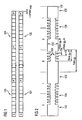
- the transmission times 121, 122 of the bits of a data block transmitted by a transponder unit are compared with the transmission times 123, 124 of the bits of the data block which are expected by the reading device.
- the data block consists of a start bit S followed by several bytes of data, each comprising 8 data bits and one parity bit P.
- the transmission times 123 of the bits expected by the reader are in good agreement with the actual transmission times 121. This is due to the fact that the reader must either be set up to detect the start of a data block or to initiate it itself.
- the error of a slightly different bit duration accumulates over the data block. Therefore, after a few bytes of data, there is a significant difference between the expected transmission times 124 of the bits and the actual transmission times 122 of the bits.
- the data block size is limited according to a first embodiment variant.
- a data signal 132 is shown, are encoded in the data bits as a sequence of two temporally successive periods in which the transmission signal is modulated differently.
- the value 1 of a data bit is represented by a signal 134 modulated in the first half of the transmission period with a subcarrier frequency and unmodulated signal 133 in the second half of the transmission period.
- the value 0 of a data bit is accordingly represented by a signal 133 unmodulated in the first half transmission period and in the second half of the transmission period with the subcarrier frequency modulated signal 134.
- quartz may have a frequency tolerance of ⁇ 1 kHz, which when using a first quartz to generate the clock frequency and another quartz to generate the frequency generator frequency can result in a frequency difference .DELTA.p PICC ⁇ PCD of up to 2 kHz, these numbers show that there is a need for realistic transponder units , the maximum data block size, which according to ISO / IEC 14443 can be up to 256 bytes, limited to up to 64 bytes. A general limitation of the data block size to 64 bytes would be possible, but would lead to a loss of speed in data transmission.
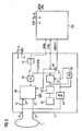
- a transponder unit which includes a high-frequency module 2 and a control chip 101.
- the control chip 101 is connected to the signal input SIGIN, the two signal outputs SIGOUT1 and SIGOUT2 and the control signal input CTRL of the radio-frequency module.
- the control chip has an input DATA / CTRL, via which it is controlled itself and via which data from other electronic components are supplied to it.
- the control chip 101 In the transmission mode, the control chip 101 generates from the supplied data a data signal, which via the signal input SIGIN to the high-frequency component is transmitted.
- This data signal is - in this specific embodiment - inverted by means of Signalinverters 47, modulated by the AND gate 50 with the frequency generator signal of the frequency generator 43, 45, amplified by the amplifier 40 and sent via the antenna 1.
- the frequency generator 43,45 generates the frequency generator signal required in the transmission mode.
- the oscillator 43 of the frequency generator is operated at a multiple frequency of the frequency generator frequency.
- the frequency generator is equipped with a divider 45, which can generate the required frequency generator signal from the oscillator signal.
- the antenna 1 is connected to the high frequency device 2 via the antenna ports LA and LB, and is connected in series with a series capacitor 41 to form a series resonant circuit.
- This series resonant circuit is connected to the outputs LA 'and LB' of the amplifier 40, so that the flowing in the resonant case RF current in the antenna resonant circuit is limited only by the ohmic resistance of the amplifier 40 and the lines. This achieves the greatest possible transmission power of the radio-frequency module.
- the control chip When generating the data signal, the control chip requires a signal at the frequency generator frequency for timing. This is supplied to the control chip via the line SIGOUT1. For this purpose, the switch 46 controlled by the control line CTRL must be in the position shown in the figure during transmission operation.
- the switch 46 is set to the opposite position.
- the smart card chip via the output SIGOUT a tapped from the antenna 1 and supplied by the signal shaper 44 digitized receive signal.
- the amplifier 40 can be switched to a power-saving mode in the receive mode via the control line CTRL in order to save energy.
- the terminals GND are for grounding and the terminals V cc-in the power supply.
- the high frequency component 2 has the in Fig. 3 illustrated embodiment, a frequency comparator 10, which compares the clock frequency of a provided by means of the antenna 1 and the signal shaper 44 clock signal with the frequency generator frequency of the frequency generator 43, 45.
- the output signal of the frequency comparator 10 is supplied to the control chip 101 via the signal output SIGOUT2.
- the control chip comprises means 102 for limiting the data block size to a maximum data block size dependent on the frequency difference. By limiting the data block size based on the frequency difference, errors of the data transmission can be avoided or limited, while at the same time the highest possible data transmission rate can be achieved.
- Fig. 4 relates to a second embodiment.
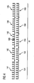
- Fig. 4 schematically illustrates a frequency generator signal 141,142,143,144,145 which has been modified by insertion of an additional pulse 160, in comparison to a clock signal 151, 152,153,154,155 shown.
- the shape of the pulses of these signals is not limited to the form exemplified in this figure.
- the comparison shown is the frequency generator signal 141 at the beginning of a predetermined time interval .DELTA.t with the clock signal 151 in phase.
- the frequency generator frequency is slightly lower than the clock frequency.
- the frequency generator signal 142,143,144 and the clock signal 152,153,154 after a few signal periods increasingly clear from the clock, so that the signals 145,155 are finally offset a whole period to each other.
- the time interval .DELTA.t was chosen exactly so that in this the clock signal exactly P pulses and the unmodified frequency generator signal has exactly P-1 pulses. In order to bring the number of pulses of the frequency generator signal over the predetermined period .DELTA.t to the total number of pulses of the clock signal, therefore, exactly one additional pulse 160 has been inserted into the frequency generator signal.
- in Fig. 5 schematically illustrated transponder unit for implementing the second embodiment follows essentially the structure of in Fig. 3 illustrated transponder unit, which the first embodiment realized.
- the transponder unit of the control chip 101 does not have means for restricting the data block size to a maximum data block size depending on the frequency difference, and the output signal of the frequency comparator 10 is not supplied to the control chip 101. Instead, the output of the frequency comparator is fed to a device 11 to modify the frequency generator signal by generating additional pulses or removing pulses in response to the frequency difference.
- the transmission time of a data bit and thus the bit rate of the data transmitted by the transponder unit can be influenced by the addition or removal of pulses. Accordingly, by adding or removing pulses as a function of the frequency difference, the bit rate of the transmitted data can be adjusted to the bit rate expected by the reader. This avoids data transfer errors that would occur if data bits are sent at a different time than expected by the reader.
Description
Die vorliegende Erfindung betrifft eine Transpondereinheit zum Übertragen von Daten zu einem Lesegerät mittels eines elektromagnetischen Feldes, ein System umfassend das Lesegerät und die Transpondereinheit sowie ein Verfahren zum Übertragen von Daten von der Transpondereinheit zu dem Lesegerät.The present invention relates to a transponder unit for transmitting data to a reading device by means of an electromagnetic field, a system comprising the reading device and the transponder unit and a method for transmitting data from the transponder unit to the reading device.
Transpondereinheiten werden zur drahtlosen Datenkommunikation insbesondere im Nahbereich eingesetzt. Bekannte Verfahren zur Datenübertragung im Nahbereich sind beispielsweise Bluetooth, WLAN, DECT, RFID oder NFC.Transponder units are used for wireless data communication, especially in the vicinity. Known methods for data transmission in the near range are, for example, Bluetooth, WLAN, DECT, RFID or NFC.
Bei RFID (Radio Frequency Identification) handelt es sich um ein Datenübertragungsverfahren mittels elektromagnetischer Felder im einem Frequenzbereich von z.B. 13.56 MHz oder 868 MHz. Das RFID-Übertragungsverfahren bietet die Möglichkeit, dem Feld des Lesegerätes die zum Betrieb des Transponders benötigte Energie mittels der zugleich zur Datenübertragung verwendeten Antenne zu entnehmen. Daher ist das RFID-Übertragungsverfahren besonders für Chipkarten geeignet, bei denen die Datenübertragung kontaktlos erfolgt.RFID (Radio Frequency Identification) is a data transmission method using electromagnetic fields in a frequency range of e.g. 13.56 MHz or 868 MHz. The RFID transmission method offers the possibility of removing the energy required for operating the transponder from the field of the reading device by means of the antenna which is also used for data transmission. Therefore, the RFID transmission method is particularly suitable for smart cards, in which the data transmission takes place without contact.
Bei NFC (Near Field Communication) handelt es sich um ein Datenübertragungsverfahren mittels elektromagnetischer Felder im Frequenzbereich 13.56 MHz. Die bei NFC eingesetzten Methoden zur Datenübertragung sind denen kontaktloser RFID-Chipkarten sehr ähnlich. NFC-Geräte können sowohl mit RFID-Chipkarten kommunizieren als auch RFID-Chipkarten simulieren.NFC (near field communication) is a data transmission method using electromagnetic fields in the frequency range 13.56 MHz. The data transfer methods used by NFC are very similar to those of contactless RFID chip cards. NFC devices can both communicate with RFID smart cards and simulate RFID smart cards.
Bei RFID und NFC kann die Datenübertragung von der Transpondereinheit (oder dem als Transponder fungierenden NFC-Gerät) zu dem Lesegerät (oder dem als Lesegerät fungierenden NFC-Gerät) insbesondere durch Last-modulation oder mittels eines Verfahrens zur Modulation des Rückstrahlquerschnitts (elektromagnetische Backscatter-Kopplung) erfolgen.In the case of RFID and NFC, the data transmission from the transponder unit (or the NFC device acting as a transponder) to the reader (or the NFC device acting as a reader) can be effected in particular by load modulation or by means of a method for modulating the return cross section (electromagnetic backscatter). Coupling).
Bei der Datenübertragung von der Transpondereinheit zu dem Lesegerät durch Lastmodulation (induktive Kopplung) wird durch Ein- und Ausschalten eines Lastwiderstandes der Wechselstrom beeinflusst, der durch ein von dem Lesegerät erzeugtes elektromagnetisches Feld in der Transponderspule induziert wird. Nach dem Prinzip der transformatorischen Kopplung bewirkt dies eine Änderung des Stromes und der Spannung an einer primären Spule des Lesegerätes, mit der das elektromagnetische Feld erzeugt wird. Hierdurch können Daten übertragen werden.In the data transmission from the transponder unit to the reader by load modulation (inductive coupling) is influenced by switching on and off of a load resistance of the alternating current, which is induced by a generated by the reader electromagnetic field in the transponder coil. According to the principle of transformer coupling, this causes a change in the current and the voltage across a primary coil of the reader, with which the electromagnetic field is generated. This allows data to be transferred.
Bei der Datenübertragung von der Transpondereinheit zu dem Lesegerät durch Modulation des Rückstrahlquerschnitts wird der Rückstrahlquerschnitt, der Aufschluss darüber gibt, wie stark ein Objekt elektromagnetische Wellen reflektiert, moduliert. Beispielsweise weisen Antennen im Resonanzfall einen besonders starken Rückstrahlquerschnitt auf.In the data transmission from the transponder unit to the reader by modulating the Rückstrahlquerschnitts the Rückstrahlquerschnitt which gives information on how much an object reflects electromagnetic waves, modulated. For example, antennas have a particularly strong return cross-section in the case of resonance.
Aus der Patentanmeldung
Bei herkömmlichen RFID/NFC-Systemen kann über eine Antenne des Transponders das von dem Lesegerät erzeugte elektromagnetische Feld ständig empfangen werden. Die Frequenz der in der Transponderantenne induzierten HF- Wechselspannung kann somit ständig ausgewertet werden und steht dem Transponder damit als Clockfrequenz zur Taktung der Datenübertragung zwischen Transponder und Lesegerät zur Verfügung. Die Clockfrequenz entspricht dann exakt der Sendefrequenz des Lesegeräts und ist an diese phasensynchron gekoppelt. Dabei ist es gleichgültig, ob die Transpondereinheit Daten vom Lesegerät empfängt, sich in einem Nichtkommunikationsmodus befindet (z.B. Abarbeitung eines Kommandos, Warten auf ein Kommando) oder Daten z. B. per Lastmodulation oder mittels modifiziertem Rückstrahlquerschnitt an das Lesegerät sendet.In conventional RFID / NFC systems, the electromagnetic field generated by the reader can be constantly received via an antenna of the transponder. The frequency of the RF alternating voltage induced in the transponder antenna can thus be continuously evaluated and is therefore available to the transponder as a clock frequency for clocking the data transmission between the transponder and the reader. The clock frequency then corresponds exactly to the transmission frequency of the reader and is coupled to this phase-synchronous. It does not matter whether the transponder unit receives data from the reader, is in a non-communication mode (e.g., processing a command, waiting for a command) or data e.g. B. transmits by load modulation or by means of modified Rückstrahlquerschnitt to the reader.
Dagegen wird bei dem durch die zuvor genannten Patentanmeldungen
Dabei kann es zu einer Frequenzdifferenz zwischen der Clockfrequenz des Lesegeräts und der Frequenzgeberfrequenz des Frequenzgebers des aktiven Transponders kommen. Dies führt in der Folge zu einer geringfügigen Abweichung zwischen der von dem Lesegerät erwarteten Bitrate und der tatsächlichen Bitrate der von der Transpondereinheit gesendeten Daten und kann zu Fehlern bei der Datenübertragung führen, wenn Datenbits zu einem anderen Zeitpunkt gesendet werden, als dies von dem Lesegerät erwartet wird.This can lead to a frequency difference between the clock frequency of the reader and the frequency generator frequency of the frequency generator of the active transponder. As a result, there will be a slight deviation between the bit rate expected by the reader and the actual bit rate of the data transmitted from the transponder unit, and may result in errors in data transmission when data bits are sent at a different time than expected by the reader becomes.
Um dieses Problem zu umgehen, schlägt die
Aufgabe der vorliegenden Erfindung ist es daher, eine aktiv sendende Transpondereinheit zur Verfügung zu stellen, welche mit einfachen Mitteln eine zuverlässige Datenübertragung gewährleistet.The object of the present invention is therefore to provide an actively transmitting transponder unit which ensures reliable data transmission by simple means.
Diese Aufgabe wird durch die Merkmale der unabhängigen Ansprüche gelöst. In davon abhängigen Ansprüchen sind vorteilhafte Ausgestaltungen und Weiterbildungen der Erfindung angegeben.This object is solved by the features of the independent claims. In dependent claims advantageous embodiments and developments of the invention are given.
Dementsprechend umfasst die Transpondereinheit zum Übertragen von Daten zu einem Lesegerät einen Empfänger zum Empfangen eines Clocksignals, das von dem Lesegerät mit einer Clockfrequenz ausgesendet wird, einen Frequenzgeber zum Generieren einer Frequenzgeberfrequenz, welche zur Taktung der Übertragung der Daten verwendet wird, und einen Frequenzvergleicher, welcher eingerichtet ist, die Frequenzdifferenz zwischen der Clockfrequenz und der Frequenzgeberfrequenz zu bestimmen. Des Weiteren umfasst die Transpondereinheit gemäß einer ersten Variante eine Einrichtung zum Beschränken der Datenblockgröße der an das Lesegerät zu sendenden Daten auf eine von der Frequenzdifferenz abhängige maximale Datenblockgröße.Accordingly, the transponder unit for transmitting data to a reader includes a receiver for receiving a clock signal sent from the reader at a clock frequency, a frequency generator for generating a frequency generator frequency used to clock the transmission of the data, and a frequency comparator is set up to determine the frequency difference between the clock frequency and the frequency generator frequency. Furthermore, according to a first variant, the transponder unit comprises a device for limiting the data block size of the data to be sent to the reading device to a maximum data block size which is dependent on the frequency difference.
Diese Lösung macht sich zunutze, dass für die ersten Bits eines Datenblocks eine Abweichung der von dem Lesegerät erwarteten Bitrate von der tatsächlichen Bitrate der von der Transpondereinheit gesendeten Daten nur zu einer geringen Abweichung des erwarteten Sendezeitpunkts eines Bits von dem tatsächlichen Sendezeitpunkt führt. Der Fehler einer sich geringfügig unterscheidenden Bitdauer summiert sich jedoch über den Datenblock hinweg auf und führt dazu, dass sich mit wachsender Größe des Datenblocks der Zeitunterschied zwischen dem erwarteten und dem tatsächlichen Sendezeitpunkt insbesondere für die letzten Bits des Datenblocks deutlich vergrößert. Um diesen Zeitunterschied nicht zu groß werden zu lassen, wird die Datenblockgröße beschränkt. Wenn die Datenblockgröße - abhängig von der Frequenzdifferenz - so beschränkt wird, dass selbst das letzte Bit eines Datenblocks nicht zu einem Zeitpunkt übertragen wird, an dem das Lesegerät bereits das nächstfolgende oder das vorhergehende Bit des Datenblocks erwartet, kann es nicht zu einem Lesefehler im Lesegerät kommen. Mittels einer Beschränkung der Datenblockgröße basierend auf der Frequenzdifferenz können somit Fehler der Datenübertragung vermieden oder begrenzt werden.This solution makes use of the fact that, for the first bits of a data block, a deviation of the bit rate expected by the reader from the actual bit rate of the data transmitted by the transponder unit only leads to a slight deviation of the expected transmission time of one bit from the actual transmission time. The error of a slightly different bit duration, however, accumulates over the data block and causes the time difference between the expected and the actual transmission time, in particular for the last bits of the data block, to increase significantly as the size of the data block increases. In order not to let this time difference become too large, the data block size is limited. If the data block size, depending on the frequency difference, is limited so that even the last bit of a data block is not transmitted at a time when the reader is already expecting the next or previous bit of the data block, there will be no read error in the reader come. By means of a restriction of the data block size based on the frequency difference Thus errors of data transmission can be avoided or limited.
Vorzugsweise wird die Datenblockgröße auf die folgende, von der Frequenzdifferenz abhängige maximale Datenblockgröße beschränkt: 
wobei ByteMaxBlock die maximale Datenblockgröße in Bytes pro Datenblock ist, fc die Frequenzgeberfrequenz ist, ΔfPICC↔PCD die Frequenzdifferenz zwischen der Clockfrequenz und der Frequenzgeberfrequenz ist, BitByte die Anzahl an Bits pro Byte ist (z.B. 8 Datenbits + 1 Paritätsbit), PulseBit die Anzahl an Pulsen pro Bit eines Hilfsträgersignals (ISO 14443: 848 KHz) ist und ΔPulsemax eine Konstante ist, welche kleiner als PulseBit/2 oder PulseBit/4 oder PulseBit/8 ist.Preferably, the data block size is limited to the following maximum data block size dependent on the frequency difference:
where Byte MaxBlock is the maximum data block size in bytes per data block, f c is the frequency generator frequency, Δf PICC↔PCD is the frequency difference between the clock frequency and the frequency generator frequency, bit byte is the number of bits per byte (eg 8 data bits + 1 parity bit), Pulse bit is the number of pulses per bit of a subcarrier signal (ISO 14443: 848 KHz) and ΔPulse max is a constant which is less than Pulse Bit / 2 or Pulse Bit / 4 or Pulse Bit / 8.
Diese Bedingung beschreibt eine Beschränkung der Datenblockgröße auf eine maximale Anzahl von Bytes ByteMaxBiock, die von der Frequenzdifferenz ΔfPICC↔PCD und von der Konstante ΔPulsemax abhängt. Die Konstante ΔPulsemax gibt den maximal zulässigen Zeitunterschied zwischen dem erwarteten und dem tatsächlichen Sendezeitpunkt des letzten Bits des Datenblocks an, gemessen in Einheiten von Clockpulsen. Dieser Zeitunterschied muss generell kleiner sein als PulseBit/2 (der Hälfte der Sendedauer eines Bits), da ein Zeitunterschied von exakt PulseBit/2 (oder mehr) bedeuten würde, dass das letzte Bit des Datenblocks zur Hälfte (oder zu mehr als der Hälfte) außerhalb des Zeitraums gesendet wird, in dem dieses von dem Lesegerät erwartet wird. Spätestens ab diesem Grenzfall ist eine fehlerfreie Datenübertragung nicht mehr möglich.This condition describes a limitation of the data block size to a maximum number of Bytes Bytes MaxBiock , which depends on the frequency difference Δf PICC↔PCD and on the constant ΔPulse max . The constant ΔPulse max indicates the maximum permissible time difference between the expected and the actual transmission time of the last bit of the data block, measured in units of clock pulses. This time difference must generally be less than Pulse Bit / 2 (half the transmission time of a bit), since a time difference of exactly Pulse bit / 2 (or more) would mean that the last bit of the data block is half (or more than the Half) is sent outside of the period in which it is expected by the reader. At least from this limiting case, error-free data transmission is no longer possible.
Häufig wird ein Datenbit auch als eine Sequenz zweier zeitlich aufeinander folgender Zeitabschnitte codiert, in denen das Sendesignal unterschiedlich moduliert wird. Beispielsweise ist es möglich, den Wert 1 eines Datenbits dadurch darzustellen, dass während der ersten Hälfte des Zeitraums, in dem das Datenbit gesendet wird, das Signal mit einer Hilfsträgerfrequenz, die typischerweise ein Bruchteil der Frequenzgeberfrequenz ist, moduliert wird und in der zweiten Hälfte des Zeitraums, in dem das Datenbit gesendet wird, das Signal nicht moduliert wird. Der Wert 0 eines Datenbits wird dann dadurch dargestellt, dass während der ersten Hälfte des Zeitraums, in dem das Datenbit gesendet wird, das Signal nicht moduliert wird und in der zweiten Hälfte des Zeitraums, in dem das Datenbit gesendet wird, das Signal mit der Hilfsträgerfrequenz moduliert wird. Bei dieser Art der Datenübertragung ist zumindest eine Beschränkung auf ΔPulsemax < PulseBit/4 erforderlich. Denn bei ΔPulsemax = PulseBit/4 fällt eine Zeitspanne, in der das Signal moduliert oder nicht moduliert wird und die wiederum einer Hälfte des Zeitraums, in dem das Datenbit gesendet wird, entspricht, nur zur Hälfte in den Zeitraum, in dem das Datenbit vom Lesegerät erwartet wird.Frequently, a data bit is also coded as a sequence of two temporally successive time segments in which the transmission signal is modulated differently. For example, it is possible to represent the
Insbesondere hat es sich bei der zuvor dargestellten Datencodierung als besonders günstig herausgestellt, wenn der maximale Versatz der Clockpulse am Ende des Datenblocks auf die Periodendauer der zur Modulation verwendeten Hilfsträgerfrequenz beschränkt wird. Falls die Daten nach der gebräuchlichen Norm ISO/IEC 14443 übertragen werden, entspricht dies genau ΔPulsemax ≤ PulseBit/8.In particular, it has turned out to be particularly favorable in the previously described data coding if the maximum offset of the clock pulses at the end of the data block is limited to the period of the subcarrier frequency used for the modulation. If the data is transmitted according to the standard ISO / IEC 14443, this corresponds exactly to ΔPulse max ≤ Pulse Bit / 8.
Entsprechend dieser Transpondereinheit, die eine Einrichtung zum Beschränken der Datenblockgröße der Daten auf eine von der Frequenzdifferenz abhängige maximale Datenblockgröße umfasst, wird desweiteren ein Verfahren zum Übertragen von Daten von einer Transpondereinheit zu einem Lesegerät vorgeschlagen. Bei diesem wird die Frequenzdifferenz zwischen der Clockfrequenz des empfangenen Clocksignals und der generierten Frequenzgeberfrequenz bestimmt, und abhängig davon wird für die Übertragung von Daten zu dem Lesegerät die Datenblockgröße der zu übertragenden Daten auf maximale Datenblockgröße beschränkt.According to this transponder unit, which includes means for restricting the data block size of the data to a frequency difference-dependent maximum data block size, there is further provided a method of transmitting data from a transponder unit to a transponder unit Reader proposed. In this, the frequency difference between the clock frequency of the received clock signal and the generated frequency generator frequency is determined, and depending on this, the data block size of the data to be transmitted is limited to maximum data block size for the transmission of data to the reading device.
In einer zweiten illustrativen Variante, wie schon bei der ersten Variante, umfasst die Transpondereinheit zum Übertragen von Daten dem Lesegerät einen Empfänger zum Empfangen eines Clocksignals, das von dem Lesegerät mit einer Clockfrequenz ausgesendet wird, einen Frequenzgeber zum Generieren eines Frequenzgebersignals mit einer Frequenzgeberfrequenz, welches aus mit der Frequenzgeberfrequenz getakteten Pulsen besteht und zur Taktung der Übertragung, der Daten verwendet wird, und einen Frequenzvergleicher, welcher eingerichtet ist, die Frequenzdifferenz zwischen der Clockfrequenz und der Frequenzgeberfrequenz zu bestimmen. Des Weiteren umfasst die Transpondereinheit jedoch bei dieser zweiten Variante eine Einrichtung zum Modifizieren des Frequenzgebersignals durch Erzeugen zusätzlicher Pulse oder Entfernen von Pulsen in Abhängigkeit von der Frequenzdifferenz.In a second illustrative variant, as in the first variant, the transponder unit for transmitting data to the reader comprises a receiver for receiving a clock signal emitted by the reader at a clock frequency, a frequency generator for generating a frequency generator signal with a frequency generator frequency, which consists of pulses clocked at the frequency generator frequency and used for timing the transmission of the data, and a frequency comparator arranged to determine the frequency difference between the clock frequency and the frequency generator frequency. Furthermore, in this second variant, however, the transponder unit comprises a device for modifying the frequency generator signal by generating additional pulses or removing pulses as a function of the frequency difference.
Bei Verwendung des modifizierten Frequenzgebersignals zur Taktung der Datenübertragung kann durch das Hinzufügen bzw. das Entfernen von Pulsen die Übertragungsdauer eines Datenbits und damit die Bitrate der von der Transpondereinheit gesendeten Daten gezielt beeinflusst werden. Dementsprechend lässt sich durch das Hinzufügen bzw. das Entfernen von Pulsen in Abhängigkeit von der ermittelten Frequenzdifferenz die Bitrate der gesendeten Daten an die von dem Lesegerät erwartete Bitrate anpassen. Hiermit können wiederum Übertragungsfehler, die entstehen würden, wenn Datenbits zu einem anderen Zeitpunkt gesendet werden, als dies von dem Lesegerät erwartet wird, reduziert bzw. vermieden werden. Somit erfolgt auch bei dieser zweiten Variante wie schon bei der ersten Variante ein Eingriff auf der Ebene der Datenstruktur. Während bei der ersten Variante die Datenpaketgröße gezielt beschränkt wird, wird bei der zweiten Variante durch Einfügen/Entfernen von Pulsen die Länge der Datenpakete beeinflusst. Beide Varianten haben zum Ergebnis, dass das Lesegerät von der bestehenden Frequenzdifferenz nichts bemerkt.When using the modified frequency generator signal for timing the data transmission, the transmission duration of a data bit and thus the bit rate of the data transmitted by the transponder unit can be influenced in a targeted manner by adding or removing pulses. Accordingly, by adding or removing pulses in response to the determined frequency difference, the bit rate of the transmitted data can be adjusted to the bit rate expected by the reader. This, in turn, reduces or eliminates transmission errors that would arise when data bits are sent at a different time than expected by the reader. Thus, done also in this second variant as in the first variant an intervention on the level of the data structure. While in the first variant, the data packet size is specifically limited, the length of the data packets is influenced in the second variant by inserting / removing pulses. Both variants have the result that the reader of the existing frequency difference noticed nothing.
Die Einrichtung zum Modifizieren des Frequenzgebersignals gemäß der zweiten Variante ist vorzugsweise eingerichtet, bei negativen Frequenzdifferenzen, bei denen die Frequenzgeberfrequenz kleiner ist als die Clockfrequenz, zusätzliche Pulse zu erzeugen, und bei positiven Frequenzdifferenzen, bei denen die Frequenzgeberfrequenz größer ist als die Clockfrequenz, Pulse aus dem Frequenzgebersignal zu entfernen. Damit kann die Zahl der Pulse des modifizierten Frequenzgebersignals über einen vorgegebenen Zeitraum in Richtung der Anzahl der Pulse des Clocksignals korrigiert werden, womit die mittlere Bitrate der gesendeten Daten näher an der von dem Lesegerät erwarteten Bitrate liegt.The device for modifying the frequency generator signal according to the second variant is preferably set up for negative frequency differences, in which the frequency generator frequency is smaller than the clock frequency to generate additional pulses, and at positive frequency differences, in which the frequency generator frequency is greater than the clock frequency, pulses to remove the frequency generator signal. Thus, the number of pulses of the modified frequency generator signal over a predetermined period of time in the direction of the number of pulses of the clock signal can be corrected, so that the average bit rate of the transmitted data is closer to the expected by the reader bit rate.
Noch bevorzugter ist die Einrichtung zum Modifizieren des Frequenzgebersignals so eingerichtet, dass sie über einen vorgegebenen Zeitraum die Gesamtzahl der Pulse des modifizierten Frequenzgebersignals genau auf die Anzahl der Pulse des Clocksignals bringt. Hierdurch wird bei Verwendung des modifizierten Frequenzgebersignals zur Taktung der Datenübertragung die über den vorgegebenen Zeitraum gemittelte Bitrate der gesendeten Daten genau an die von dem Lesegerät erwartete Bitrate angeglichen.More preferably, the means for modifying the frequency generator signal is arranged to bring the total number of pulses of the modified frequency generator signal exactly to the number of pulses of the clock signal over a predetermined period of time. As a result, when using the modified frequency generator signal for timing the data transmission, the bitrate of the data transmitted averaged over the predetermined period of time is exactly matched to the bit rate expected by the reading device.
Entsprechend dieser Transpondereinheit, die eine Einrichtung zum Modifizieren des Frequenzgebersignals durch Erzeugen zusätzlicher Pulse oder Entfernen von Pulsen in Abhängigkeit von der Frequenzdifferenz umfasst, wird ein Verfahren zum Übertragen von Daten von einer Transpondereinheit zu einem Lesegerät vorgeschlagen. Bei diesem wird wiederum die Frequenzdifferenz zwischen der Clockfrequenz des empfangenen Clocksignals und der Frequenzgeberfrequenz des generierten Frequenzgebersignals bestimmt und in Anhängigkeit davon das Frequenzgebersignal durch Erzeugen zusätzlicher Pulse oder Entfernen von Pulsen modifiziert, wobei das Übertragen der Daten unter Verwendung des modifizierten Frequenzgebersignals erfolgt.According to this transponder unit comprising means for modifying the frequency generator signal by generating additional pulses or removing pulses as a function of the frequency difference, For example, a method for transmitting data from a transponder unit to a reader is proposed. This again determines the frequency difference between the clock frequency of the received clock signal and the frequency generator frequency of the generated frequency generator signal and, depending thereon, modifies the frequency generator signal by generating additional pulses or removing pulses, the data being transmitted using the modified frequency generator signal.
Zudem sendet die Transpondereinheit die Daten vorzugsweise aktiv zu dem Lesegerät in einer Weise, dass das vom Lesegerät empfangene Signal als eine Modulation eines von dem Lesegerät erzeugten elektromagnetischen Feldes (z. B. Lastmodulation oder Modulation eines Rückstrahlquerschnitts) auswertbar ist.In addition, the transponder unit preferably actively sends the data to the reader in such a way that the signal received by the reader is evaluable as a modulation of an electromagnetic field generated by the reader (eg load modulation or modulation of a return beam cross section).
Die Erfindung wird nachfolgend anhand der beiliegenden Zeichnungen beispielhaft erläutert. Es zeigen:
- Fig.1
- schematisch einen Vergleich der Sendezeitpunkte der Bits eines von einer Transpondereinheit gesendeten Datenblocks mit den von einem Lesegerät erwarteten Sendezeitpunkten,
- Fig. 2
- schematisch das Hochfrequenzsignal einer herkömmlichen Lastmodulation, aus dem Werte für ΔPulsemax abgeleitet werden können,
- Fig. 3
- schematisch eine Transpondereinheit gemäß einer ersten Variante mit einer Einrichtung zum Beschränken der Datenblockgröße der zu übertragenden Daten,
- Fig. 4
- schematisch ein Frequenzgebersignal, das im Vergleich zu einem Clocksignal durch Einfügen eines zusätzlichen Pulses modifiziert wurde, und
- Fig. 5
- schematisch eine Transpondereinheit gemäß einer zweiten Variante mit einer Einrichtung zum Modifizieren eines Frequenzgebersignals durch Erzeugen zusätzlicher Pulse oder Entfernen von Pulsen.
- Fig.1
- schematically a comparison of the transmission times of the bits of a data block sent by a transponder unit with the transmission times expected by a reader,
- Fig. 2
- schematically the high-frequency signal of a conventional load modulation, from which values for ΔPulse max can be derived,
- Fig. 3
- 1 schematically shows a transponder unit according to a first variant with a device for limiting the data block size of the data to be transmitted,
- Fig. 4
- schematically a frequency generator signal that has been modified compared to a clock signal by inserting an additional pulse, and
- Fig. 5
- schematically a transponder unit according to a second variant with a device for modifying a frequency generator signal by generating additional pulses or removing pulses.
In
Um diesen Zeitunterschied nicht zu groß werden zu lassen, wird gemäß einer ersten Ausführungsvariante die Datenblockgröße beschränkt. Hierbei ist es generell erforderlich, die Datenblockgröße so zu beschränken, dass der maximal zulässige Zeitunterschied ΔPulsemax zwischen dem erwarteten und dem tatsächlichen Sendezeitpunkt des letzten Bits des Datenblocks kleiner ist als die Hälfte PulseBit/2 der Sendedauer PulseBit eines Bits, da sonst das letzte Bit des Datenblocks zur Hälfte oder zu mehr als der Hälfte außerhalb des Zeitraums gesendet wird, in dem dies von dem Lesegerät erwartet wird, und damit nicht mehr korrekt zugeordnet werden kann.In order not to let this time difference become too large, the data block size is limited according to a first embodiment variant. In this case, it is generally necessary to limit the data block size in such a way that the maximum permissible time difference ΔPulse max between the expected and the actual transmission time of the last bit of the data block is less than half the pulse bit / 2 of the transmission duration pulse bit of one bit, otherwise the latest Bit of the data block is sent in half or more than half outside the period in which this is expected by the reader, and thus can not be correctly assigned.
In
Zudem hat es sich bei dieser Codierung des Datensignals als besonders günstig herausgestellt, wenn der maximale Versatz der Clockpulse am Ende des Datenblocks auf die Periodendauer der zur Modulation verwendeten Hilfsträgerfrequenz beschränkt wird. Falls die Daten nach der gebräuchlichen Norm ISO/ IEC 14443 übertragen werden, entspricht dies genau ΔPulsemax ≤ PulseBit/8.Moreover, in this coding of the data signal, it has proven to be particularly favorable if the maximum offset of the clock pulses at the end of the data block is limited to the period of the subcarrier frequency used for the modulation. If the data is transmitted according to the standard ISO / IEC 14443, this corresponds exactly to ΔPulse max ≤ Pulse Bit / 8.
Aus der Eingangs angegebenen Gleichung ergibt sich bei eine Frequenzgeberfrequenz fc von 13.56 MHz, einer Bytelänge BitByte = 9 (8 Datenbits und einen Paritätsbit) und einem maximal zulässigen Zeitversatz ΔPulsemax = PulseBit/8 eine maximale Datenblockgröße von ByteMaxBlock ≤ 256 Bytes, wenn die Frequenzdifferenz ΔfPICC↔PCD zwischen der Clockfrequenz und der Frequenzgeberfrequenz 735 Hz nicht überschreitet. Dementsprechend ergibt sich eine maximale Datenblockgröße von ByteMaxBlock ≤ 128 Bytes für die doppelte Frequenzdifferenz von 1470 Hz und eine maximale Datenblockgröße von ByteMaxBlock ≤ 64 Bytes für die vierfache Frequenzdifferenz von 2940 Hz. Da beispielsweise Quarze eine Frequenztoleranz von ± 1 kHz aufweisen können, was bei Verwendung eines ersten Quarzes zur Erzeugung der Clockfrequenz und eines weiteren Quarzes zur Erzeugung der Frequenzgeberfrequenz eine Frequenzdifferenz ΔfPICC↔PCD von bis zu 2 kHz ergeben kann, zeigen diese Zahlen, dass bei realistischen Transpondereinheiten durchaus Bedarf besteht, die maximale Datenblockgröße, welche nach ISO/IEC 14443 bis zu 256 Byte betragen kann, auf bis zu 64 Bytes zu beschränken. Eine generelle Begrenzung der Datenblockgröße auf 64 Bytes wäre zwar möglich, würde aber zu Geschwindigkeitseinbußen bei der Datenübertragung führen.The equation given in the equation results in a frequency generator frequency f c of 13.56 MHz, a byte length of bit byte = 9 (8 data bits and a parity bit) and a maximum allowable time offset ΔPulse max = pulse bit / 8 a maximum data block size of byte MaxBlock ≤ 256 bytes, if the frequency difference Δf PICC↔PCD between the clock frequency and the frequency generator frequency does not exceed 735 Hz. Accordingly, a maximum data block size of byte MaxBlock ≤ 128 bytes for the double frequency difference of 1470 Hz and a maximum data block size of byte MaxBlock ≤ 64 bytes for the quadruple frequency difference of 2940 Hz. For example, since quartz may have a frequency tolerance of ± 1 kHz, which when using a first quartz to generate the clock frequency and another quartz to generate the frequency generator frequency can result in a frequency difference .DELTA.p PICC↔PCD of up to 2 kHz, these numbers show that there is a need for realistic transponder units , the maximum data block size, which according to ISO / IEC 14443 can be up to 256 bytes, limited to up to 64 bytes. A general limitation of the data block size to 64 bytes would be possible, but would lead to a loss of speed in data transmission.
In
Der Steuerungschip 101 ist an den Signaleingang SIGIN, die zwei Signalausgänge SIGOUT1 und SIGOUT2 sowie den Steuersignaleingang CTRL des Hochfrequenzbausteins angeschlossen. Zudem besitzt der Steuerungschip einen Eingang DATA/CTRL, über den er selbst angesteuert wird und über den ihm Daten von weiteren elektronischen Bauteilen zugeführt werden.The
Im Sendebetrieb generiert der Steuerungschip 101 aus den zugeführten Daten ein Datensignal, welches über den Signaleingang SIGIN zu dem Hochfrequenzbaustein übertragen wird. Dieses Datensignal wird - in dieser konkreten Ausführungsform - mittels Signalinverters 47 invertiert, mittels des UND-Gatters 50 mit dem Frequenzgebersignal des Frequenzgebers 43, 45 moduliert, durch den Verstärker 40 verstärkt und über die Antenne 1 gesendet.In the transmission mode, the
Der Frequenzgeber 43,45 erzeugt das im Sendebetrieb benötigte Frequenzgebersignal. Der Oszillator 43 des Frequenzgebers wird mit einer mehrfachen Frequenz der Frequenzgeberfrequenz betrieben. Zudem ist der Frequenzgeber mit einem Teiler 45 ausgestattet, der aus dem Oszillatorsignal das benötigte Frequenzgebersignal erzeugen kann. Ein Vorteil dieser Anordnung besteht darin, dass, wenn im Empfangsbetrieb des Transponders das Frequenzgebersignal nicht benötigt wird, der Teiler außer Betrieb gesetzt werden kann, um Signalstörungen zu vermindern.The
Die Antenne 1 ist über die Antennenanschlüsse LA und LB mit dem Hochfrequenzbaustein 2 verbunden und ist mit einer Serienkapazität 41 in Reihe geschaltet, um einen Reihenschwingkreis zu bilden. Dieser Reihenschwingkreis ist mit den Ausgängen LA' und LB' des Verstärkers 40 verbunden, so dass der im Resonanzfall fließende HF-Strom im Antennenschwingkreis nur durch den ohmschen Widerstand des Verstärkers 40 und der Leitungen begrenzt wird. Dadurch wird eine größtmögliche Sendeleistung des Hochfrequenzbausteins erreicht.The
Bei der Erzeugung des Datensignals benötigt der Steuerungschip ein Signal mit der Frequenzgeberfrequenz zur Taktung. Dieses wird dem Steuerungschip über die Leitung SIGOUT1 zugeführt. Hierzu muss sich der durch die Steuerleitung CTRL angesteuerte Schalter 46 während des Sendebetriebs in der in der Abbildung dargestellten Position befinden.When generating the data signal, the control chip requires a signal at the frequency generator frequency for timing. This is supplied to the control chip via the line SIGOUT1. For this purpose, the
Im Empfangsbetrieb wird der Schalter 46 auf die entgegengesetzte Position gesetzt. In diesem Fall wird dem Smart-Card-Chip über den Ausgang SIGOUT ein von der Antenne 1 abgegriffenes und mittels des Signalformers 44 digitalisiertes Empfangssignal zugeführt. Über die Steuerleitung CTRL kann zudem der Verstärker 40 im Empfangsbetrieb in einen Stromsparmodus geschaltet werden, um Energie zu sparen.In the receive mode, the
Die Anschlüsse GND dienen der Erdung und die Anschlüsse Vcc-in der Energieversorgung.The terminals GND are for grounding and the terminals V cc-in the power supply.
Darüberhinaus besitzt das Hochfrequenzbauteil 2 bei der in
Der Aufbau der in
Claims (7)
- A transponder unit (1, 2, 101) for transferring data in data blocks to a reading device by means of an electromagnetic field, comprising- a receiver (1, 44) for receiving a clock signal (151, 152, 153, 154, 155) emitted by the reading device, at a clock frequency,- a frequency generator (43, 45) for generating a frequency generator frequency which is employed for clocking the transfer of the data, and- a frequency comparator (10) which is adapted to determine the frequency difference between the clock frequency and the frequency generator frequency, characterized by a device (102) for restricting the data block size of the data to a maximum data block size dependent on the frequency difference.
- The transponder unit (1, 2, 101) according to claim 1, characterized in that the device (102) for restricting the data block size of the data is adapted to restrict the data block size to the following data block size ByteMaxBlock dependent on the frequency difference:

where ByteMaxBlock is the data block size in bytes per data block, fc is the frequency generator frequency, ΔfPICC↔PCD is the frequency difference between the clock frequency and the frequency generator frequency, BitByte is the number of bits per byte, PulseBit is the number of pulses of the frequency generator signal (141, 142, 143, 144, 145) per bit, and ΔPulsemax is a constant which is smaller than PulseBit/2 or PulseBit/4 or smaller than or equal to PulseBit/8. - The transponder unit (1, 2, 101) according to either of claims 1 to 2, characterized in that the transponder unit (1, 2, 101) is adapted to actively transmit data such that the signal (132) generated thereby is evaluable as a modulation of an electromagnetic field generated by the reading device.
- A system for data transfer, characterized by at least one transponder unit (1, 2, 101) according to any of claims 1 to 3, and a reading device which is adapted for communication with the transponder unit.
- A method for transferring data in data blocks from a transponder unit (1, 2, 101) to a reading device by means of an electromagnetic field, comprising the following steps:- receiving a clock signal (151, 152, 153, 154, 155) emitted by the reading device, at a clock frequency,- generating a frequency generator frequency in the transponder unit,- determining the frequency difference between the clock frequency and the frequency generator frequency, and- transferring data from the transponder unit to the reading device by means of an electromagnetic field employing the frequency generator frequency, characterized in that the data block size of the data to be transferred is restricted to a maximum data block size dependent on the frequency difference.
- The method according to claim 5, characterized in that the data block size is restricted to the following data block size ByteMaxBlock dependent on the frequency difference:

where ByteMaxBlock is the data block size in bytes per data block, fc is the frequency generator frequency, ΔfPICC↔PCD is the frequency difference between the clock frequency and the frequency generator frequency, BitByte is the number of bits per byte, PulseBit is the number of pulses of the frequency generator signal (141, 142, 143, 144, 145) per bit, and ΔPulsemax is a constant which is smaller than PulseBit/2 or PulseBit/4 or smaller than or equal to PulseBit/8. - The method according to either of claims 5 to 6, characterized in that in the step of transferring the data to the reading device, the transponder unit (1, 2, 101) actively transmits data such that the signal (132) generated thereby is evaluable as a modulation of an electromagnetic field generated by the reading device.
Priority Applications (1)
| Application Number | Priority Date | Filing Date | Title |
|---|---|---|---|
| EP12002414.6A EP2474940B1 (en) | 2008-10-24 | 2009-10-23 | Transponder unit |
Applications Claiming Priority (2)
| Application Number | Priority Date | Filing Date | Title |
|---|---|---|---|
| DE102008053097A DE102008053097A1 (en) | 2008-10-24 | 2008-10-24 | transponder unit |
| PCT/EP2009/007613 WO2010046128A2 (en) | 2008-10-24 | 2009-10-23 | Transponder unit |
Related Child Applications (2)
| Application Number | Title | Priority Date | Filing Date |
|---|---|---|---|
| EP12002414.6A Division EP2474940B1 (en) | 2008-10-24 | 2009-10-23 | Transponder unit |
| EP12002414.6A Division-Into EP2474940B1 (en) | 2008-10-24 | 2009-10-23 | Transponder unit |
Publications (2)
| Publication Number | Publication Date |
|---|---|
| EP2340512A2 EP2340512A2 (en) | 2011-07-06 |
| EP2340512B1 true EP2340512B1 (en) | 2015-08-05 |
Family
ID=41478772
Family Applications (2)
| Application Number | Title | Priority Date | Filing Date |
|---|---|---|---|
| EP09743864.2A Not-in-force EP2340512B1 (en) | 2008-10-24 | 2009-10-23 | Transponder unit |
| EP12002414.6A Not-in-force EP2474940B1 (en) | 2008-10-24 | 2009-10-23 | Transponder unit |
Family Applications After (1)
| Application Number | Title | Priority Date | Filing Date |
|---|---|---|---|
| EP12002414.6A Not-in-force EP2474940B1 (en) | 2008-10-24 | 2009-10-23 | Transponder unit |
Country Status (4)
| Country | Link |
|---|---|
| US (1) | US8766776B2 (en) |
| EP (2) | EP2340512B1 (en) |
| DE (1) | DE102008053097A1 (en) |
| WO (1) | WO2010046128A2 (en) |
Families Citing this family (2)
| Publication number | Priority date | Publication date | Assignee | Title |
|---|---|---|---|---|
| DE102011101763A1 (en) * | 2011-05-17 | 2012-11-22 | Giesecke & Devrient Gmbh | Method for coupling transmission signal phase of active read-modulating data carrier with carrier signal phase of reader, involves performing specific modulation process during transmission of modulated transmitting signal |
| US10263764B2 (en) * | 2016-05-03 | 2019-04-16 | The Boeing Company | Auto-adaptive digital clock system and method for optimizing data communications |
Family Cites Families (10)
| Publication number | Priority date | Publication date | Assignee | Title |
|---|---|---|---|---|
| US4590440A (en) * | 1984-07-06 | 1986-05-20 | American Microsystems, Inc. | Phase locked loop with high and/or low frequency limit detectors for preventing false lock on harmonics |
| JP3200851B2 (en) * | 1993-10-08 | 2001-08-20 | ソニー株式会社 | Digital signal processing device, digital signal processing method, and data recording medium |
| US5828954A (en) * | 1996-04-04 | 1998-10-27 | Lucent Technologies Inc. | Transmission system for digital audio broadcasting |
| DE69827908T2 (en) * | 1997-04-24 | 2005-12-22 | Koninklijke Philips Electronics N.V. | TRANSPONDER FOR TOUCHLESS INDUCTIVE COMMUNICATION |
| US6879809B1 (en) * | 1998-04-16 | 2005-04-12 | Motorola, Inc. | Wireless electrostatic charging and communicating system |
| DE10353500B4 (en) * | 2003-11-11 | 2005-09-08 | Siemens Ag | Method and device for synchronizing data transmission between data pumps |
| DE102004031092A1 (en) | 2004-06-28 | 2006-01-12 | Giesecke & Devrient Gmbh | transponder unit |
| DE102005061660A1 (en) | 2005-12-22 | 2007-06-28 | Giesecke & Devrient Gmbh | Portable data carrier with active contactless interface |
| DE102005061438A1 (en) | 2005-12-22 | 2007-07-05 | Atmel Germany Gmbh | Transponder and method for operating a transponder |
| TWI324320B (en) * | 2006-09-01 | 2010-05-01 | Ind Tech Res Inst | Rfid tag system and data stream thereof |
-
2008
- 2008-10-24 DE DE102008053097A patent/DE102008053097A1/en not_active Withdrawn
-
2009
- 2009-10-23 EP EP09743864.2A patent/EP2340512B1/en not_active Not-in-force
- 2009-10-23 WO PCT/EP2009/007613 patent/WO2010046128A2/en active Application Filing
- 2009-10-23 US US13/125,706 patent/US8766776B2/en active Active
- 2009-10-23 EP EP12002414.6A patent/EP2474940B1/en not_active Not-in-force
Also Published As
| Publication number | Publication date |
|---|---|
| EP2474940A1 (en) | 2012-07-11 |
| EP2474940B1 (en) | 2014-09-10 |
| DE102008053097A1 (en) | 2010-04-29 |
| EP2340512A2 (en) | 2011-07-06 |
| WO2010046128A3 (en) | 2010-07-22 |
| US8766776B2 (en) | 2014-07-01 |
| US20110260837A1 (en) | 2011-10-27 |
| WO2010046128A2 (en) | 2010-04-29 |
Similar Documents
| Publication | Publication Date | Title |
|---|---|---|
| EP1587023B1 (en) | Method for data communication between a base station and a transponder | |
| EP0502518B1 (en) | Wireless data transmission method on a data carrier | |
| DE69922587T2 (en) | transfer process | |
| DE60307318T2 (en) | METHOD FOR RECOGNIZING A GROUP ASSIGNMENT OF TRANSPONDER | |
| DE102013008516B3 (en) | Transponder unit, system and method for contactless data transmission | |
| EP1818858A2 (en) | Transponder and method for wireless data transfer | |
| EP2340512B1 (en) | Transponder unit | |
| EP1735735B1 (en) | Method and device for recognizing functional states in rfid systems or remote sensor systems | |
| EP1470520B1 (en) | Method for transmitting data between a base station and a transponder | |
| DE102006057602B3 (en) | Wireless data transmission method for use in radio frequency identification system, involves assigning time durations to symbol values and selecting data transmission protocol type by describing configuration register in passive transponder | |
| EP1728191B1 (en) | Method for datacommunication between a base station and a transponder | |
| WO1997007413A1 (en) | Frequency-hopping for passive and semi-passive telemetry and identification systems | |
| DE10204347A1 (en) | Process for the transmission of data | |
| EP2141637B1 (en) | Portable data carrier with active contactless interface and operating method | |
| DE102004006446A1 (en) | Method and circuit arrangement for wireless data transmission | |
| DE102008040453B4 (en) | Non-contact communication device and method for contactless communication | |
| EP1587022B1 (en) | Method for wireless data transfer | |
| AT401127B (en) | CONTACTLESS DATA TRANSFER SYSTEM | |
| DE102004019311B3 (en) | Method and device for wireless data transmission | |
| DE102018124480B4 (en) | COMMUNICATION DEVICE AND METHOD OF OPERATING AN ANTENNA TURN CIRCUIT | |
| DE102011119687A1 (en) | Transponder unit, system and method for contactless data transmission | |
| EP3259700B1 (en) | Wireless card reader | |
| DE102004018542A1 (en) | Method for data communication between a base station and a transponder | |
| DE102004016335B4 (en) | Method for contactless data transmission | |
| DE102009054296A1 (en) | Interface unit i.e. near field communication interface, for use in e.g. micro secure digital card in radio frequency identification system for contactless transmission of signals, has high frequency circuit switched into receiving mode |
Legal Events
| Date | Code | Title | Description |
|---|---|---|---|
| PUAI | Public reference made under article 153(3) epc to a published international application that has entered the european phase |
Free format text: ORIGINAL CODE: 0009012 |
|
| 17P | Request for examination filed |
Effective date: 20110524 |
|
| AK | Designated contracting states |
Kind code of ref document: A2 Designated state(s): AT BE BG CH CY CZ DE DK EE ES FI FR GB GR HR HU IE IS IT LI LT LU LV MC MK MT NL NO PL PT RO SE SI SK SM TR |
|
| AX | Request for extension of the european patent |
Extension state: AL BA RS |
|
| DAX | Request for extension of the european patent (deleted) | ||
| GRAP | Despatch of communication of intention to grant a patent |
Free format text: ORIGINAL CODE: EPIDOSNIGR1 |
|
| RIC1 | Information provided on ipc code assigned before grant |
Ipc: G06K 19/077 20060101ALI20150317BHEP Ipc: H04B 1/62 20060101ALI20150317BHEP Ipc: H04B 7/00 20060101ALI20150317BHEP Ipc: H04B 5/00 20060101ALI20150317BHEP Ipc: G06K 19/07 20060101AFI20150317BHEP |
|
| INTG | Intention to grant announced |
Effective date: 20150331 |
|
| GRAS | Grant fee paid |
Free format text: ORIGINAL CODE: EPIDOSNIGR3 |
|
| GRAA | (expected) grant |
Free format text: ORIGINAL CODE: 0009210 |
|
| AK | Designated contracting states |
Kind code of ref document: B1 Designated state(s): AT BE BG CH CY CZ DE DK EE ES FI FR GB GR HR HU IE IS IT LI LT LU LV MC MK MT NL NO PL PT RO SE SI SK SM TR |
|
| REG | Reference to a national code |
Ref country code: GB Ref legal event code: FG4D Free format text: NOT ENGLISH |
|
| REG | Reference to a national code |
Ref country code: CH Ref legal event code: EP |
|
| REG | Reference to a national code |
Ref country code: AT Ref legal event code: REF Ref document number: 741081 Country of ref document: AT Kind code of ref document: T Effective date: 20150815 |
|
| REG | Reference to a national code |
Ref country code: IE Ref legal event code: FG4D Free format text: LANGUAGE OF EP DOCUMENT: GERMAN |
|
| REG | Reference to a national code |
Ref country code: DE Ref legal event code: R096 Ref document number: 502009011368 Country of ref document: DE |
|
| REG | Reference to a national code |
Ref country code: FR Ref legal event code: PLFP Year of fee payment: 7 |
|
| REG | Reference to a national code |
Ref country code: LT Ref legal event code: MG4D |
|
| REG | Reference to a national code |
Ref country code: NL Ref legal event code: MP Effective date: 20150805 |
|
| PG25 | Lapsed in a contracting state [announced via postgrant information from national office to epo] |
Ref country code: LV Free format text: LAPSE BECAUSE OF FAILURE TO SUBMIT A TRANSLATION OF THE DESCRIPTION OR TO PAY THE FEE WITHIN THE PRESCRIBED TIME-LIMIT Effective date: 20150805 Ref country code: NO Free format text: LAPSE BECAUSE OF FAILURE TO SUBMIT A TRANSLATION OF THE DESCRIPTION OR TO PAY THE FEE WITHIN THE PRESCRIBED TIME-LIMIT Effective date: 20151105 Ref country code: LT Free format text: LAPSE BECAUSE OF FAILURE TO SUBMIT A TRANSLATION OF THE DESCRIPTION OR TO PAY THE FEE WITHIN THE PRESCRIBED TIME-LIMIT Effective date: 20150805 Ref country code: GR Free format text: LAPSE BECAUSE OF FAILURE TO SUBMIT A TRANSLATION OF THE DESCRIPTION OR TO PAY THE FEE WITHIN THE PRESCRIBED TIME-LIMIT Effective date: 20151106 Ref country code: FI Free format text: LAPSE BECAUSE OF FAILURE TO SUBMIT A TRANSLATION OF THE DESCRIPTION OR TO PAY THE FEE WITHIN THE PRESCRIBED TIME-LIMIT Effective date: 20150805 |
|
| PG25 | Lapsed in a contracting state [announced via postgrant information from national office to epo] |
Ref country code: HR Free format text: LAPSE BECAUSE OF FAILURE TO SUBMIT A TRANSLATION OF THE DESCRIPTION OR TO PAY THE FEE WITHIN THE PRESCRIBED TIME-LIMIT Effective date: 20150805 Ref country code: PL Free format text: LAPSE BECAUSE OF FAILURE TO SUBMIT A TRANSLATION OF THE DESCRIPTION OR TO PAY THE FEE WITHIN THE PRESCRIBED TIME-LIMIT Effective date: 20150805 Ref country code: PT Free format text: LAPSE BECAUSE OF FAILURE TO SUBMIT A TRANSLATION OF THE DESCRIPTION OR TO PAY THE FEE WITHIN THE PRESCRIBED TIME-LIMIT Effective date: 20151207 Ref country code: IS Free format text: LAPSE BECAUSE OF FAILURE TO SUBMIT A TRANSLATION OF THE DESCRIPTION OR TO PAY THE FEE WITHIN THE PRESCRIBED TIME-LIMIT Effective date: 20151205 Ref country code: SE Free format text: LAPSE BECAUSE OF FAILURE TO SUBMIT A TRANSLATION OF THE DESCRIPTION OR TO PAY THE FEE WITHIN THE PRESCRIBED TIME-LIMIT Effective date: 20150805 Ref country code: ES Free format text: LAPSE BECAUSE OF FAILURE TO SUBMIT A TRANSLATION OF THE DESCRIPTION OR TO PAY THE FEE WITHIN THE PRESCRIBED TIME-LIMIT Effective date: 20150805 |
|
| PG25 | Lapsed in a contracting state [announced via postgrant information from national office to epo] |
Ref country code: NL Free format text: LAPSE BECAUSE OF FAILURE TO SUBMIT A TRANSLATION OF THE DESCRIPTION OR TO PAY THE FEE WITHIN THE PRESCRIBED TIME-LIMIT Effective date: 20150805 |
|
| PG25 | Lapsed in a contracting state [announced via postgrant information from national office to epo] |
Ref country code: DK Free format text: LAPSE BECAUSE OF FAILURE TO SUBMIT A TRANSLATION OF THE DESCRIPTION OR TO PAY THE FEE WITHIN THE PRESCRIBED TIME-LIMIT Effective date: 20150805 Ref country code: EE Free format text: LAPSE BECAUSE OF FAILURE TO SUBMIT A TRANSLATION OF THE DESCRIPTION OR TO PAY THE FEE WITHIN THE PRESCRIBED TIME-LIMIT Effective date: 20150805 Ref country code: IT Free format text: LAPSE BECAUSE OF FAILURE TO SUBMIT A TRANSLATION OF THE DESCRIPTION OR TO PAY THE FEE WITHIN THE PRESCRIBED TIME-LIMIT Effective date: 20150805 Ref country code: CZ Free format text: LAPSE BECAUSE OF FAILURE TO SUBMIT A TRANSLATION OF THE DESCRIPTION OR TO PAY THE FEE WITHIN THE PRESCRIBED TIME-LIMIT Effective date: 20150805 Ref country code: SK Free format text: LAPSE BECAUSE OF FAILURE TO SUBMIT A TRANSLATION OF THE DESCRIPTION OR TO PAY THE FEE WITHIN THE PRESCRIBED TIME-LIMIT Effective date: 20150805 |
|
| REG | Reference to a national code |
Ref country code: DE Ref legal event code: R097 Ref document number: 502009011368 Country of ref document: DE |
|
| PG25 | Lapsed in a contracting state [announced via postgrant information from national office to epo] |
Ref country code: RO Free format text: LAPSE BECAUSE OF FAILURE TO SUBMIT A TRANSLATION OF THE DESCRIPTION OR TO PAY THE FEE WITHIN THE PRESCRIBED TIME-LIMIT Effective date: 20150805 Ref country code: LU Free format text: LAPSE BECAUSE OF FAILURE TO SUBMIT A TRANSLATION OF THE DESCRIPTION OR TO PAY THE FEE WITHIN THE PRESCRIBED TIME-LIMIT Effective date: 20151023 |
|
| REG | Reference to a national code |
Ref country code: CH Ref legal event code: PL |
|
| PLBE | No opposition filed within time limit |
Free format text: ORIGINAL CODE: 0009261 |
|
| STAA | Information on the status of an ep patent application or granted ep patent |
Free format text: STATUS: NO OPPOSITION FILED WITHIN TIME LIMIT |
|
| PG25 | Lapsed in a contracting state [announced via postgrant information from national office to epo] |
Ref country code: MC Free format text: LAPSE BECAUSE OF FAILURE TO SUBMIT A TRANSLATION OF THE DESCRIPTION OR TO PAY THE FEE WITHIN THE PRESCRIBED TIME-LIMIT Effective date: 20150805 |
|
| 26N | No opposition filed |
Effective date: 20160509 |
|
| REG | Reference to a national code |
Ref country code: IE Ref legal event code: MM4A |
|
| PG25 | Lapsed in a contracting state [announced via postgrant information from national office to epo] |
Ref country code: LI Free format text: LAPSE BECAUSE OF NON-PAYMENT OF DUE FEES Effective date: 20151031 Ref country code: CH Free format text: LAPSE BECAUSE OF NON-PAYMENT OF DUE FEES Effective date: 20151031 |
|
| PG25 | Lapsed in a contracting state [announced via postgrant information from national office to epo] |
Ref country code: SI Free format text: LAPSE BECAUSE OF FAILURE TO SUBMIT A TRANSLATION OF THE DESCRIPTION OR TO PAY THE FEE WITHIN THE PRESCRIBED TIME-LIMIT Effective date: 20150805 |
|
| REG | Reference to a national code |
Ref country code: FR Ref legal event code: PLFP Year of fee payment: 8 |
|
| PG25 | Lapsed in a contracting state [announced via postgrant information from national office to epo] |
Ref country code: IE Free format text: LAPSE BECAUSE OF NON-PAYMENT OF DUE FEES Effective date: 20151023 |
|
| REG | Reference to a national code |
Ref country code: AT Ref legal event code: MM01 Ref document number: 741081 Country of ref document: AT Kind code of ref document: T Effective date: 20151023 |
|
| PG25 | Lapsed in a contracting state [announced via postgrant information from national office to epo] |
Ref country code: AT Free format text: LAPSE BECAUSE OF NON-PAYMENT OF DUE FEES Effective date: 20151023 |
|
| PG25 | Lapsed in a contracting state [announced via postgrant information from national office to epo] |
Ref country code: HU Free format text: LAPSE BECAUSE OF FAILURE TO SUBMIT A TRANSLATION OF THE DESCRIPTION OR TO PAY THE FEE WITHIN THE PRESCRIBED TIME-LIMIT; INVALID AB INITIO Effective date: 20091023 Ref country code: BG Free format text: LAPSE BECAUSE OF FAILURE TO SUBMIT A TRANSLATION OF THE DESCRIPTION OR TO PAY THE FEE WITHIN THE PRESCRIBED TIME-LIMIT Effective date: 20150805 Ref country code: SM Free format text: LAPSE BECAUSE OF FAILURE TO SUBMIT A TRANSLATION OF THE DESCRIPTION OR TO PAY THE FEE WITHIN THE PRESCRIBED TIME-LIMIT Effective date: 20150805 |
|
| PG25 | Lapsed in a contracting state [announced via postgrant information from national office to epo] |
Ref country code: CY Free format text: LAPSE BECAUSE OF FAILURE TO SUBMIT A TRANSLATION OF THE DESCRIPTION OR TO PAY THE FEE WITHIN THE PRESCRIBED TIME-LIMIT Effective date: 20150805 |
|
| REG | Reference to a national code |
Ref country code: DE Ref legal event code: R081 Ref document number: 502009011368 Country of ref document: DE Owner name: GIESECKE+DEVRIENT MOBILE SECURITY GMBH, DE Free format text: FORMER OWNER: GIESECKE & DEVRIENT GMBH, 81677 MUENCHEN, DE |
|
| PG25 | Lapsed in a contracting state [announced via postgrant information from national office to epo] |
Ref country code: BE Free format text: LAPSE BECAUSE OF NON-PAYMENT OF DUE FEES Effective date: 20151031 |
|
| PG25 | Lapsed in a contracting state [announced via postgrant information from national office to epo] |
Ref country code: MT Free format text: LAPSE BECAUSE OF FAILURE TO SUBMIT A TRANSLATION OF THE DESCRIPTION OR TO PAY THE FEE WITHIN THE PRESCRIBED TIME-LIMIT Effective date: 20150805 Ref country code: TR Free format text: LAPSE BECAUSE OF FAILURE TO SUBMIT A TRANSLATION OF THE DESCRIPTION OR TO PAY THE FEE WITHIN THE PRESCRIBED TIME-LIMIT Effective date: 20150805 |
|
| REG | Reference to a national code |
Ref country code: FR Ref legal event code: PLFP Year of fee payment: 9 |
|
| REG | Reference to a national code |
Ref country code: GB Ref legal event code: 732E Free format text: REGISTERED BETWEEN 20180118 AND 20180124 |
|
| PG25 | Lapsed in a contracting state [announced via postgrant information from national office to epo] |
Ref country code: MK Free format text: LAPSE BECAUSE OF FAILURE TO SUBMIT A TRANSLATION OF THE DESCRIPTION OR TO PAY THE FEE WITHIN THE PRESCRIBED TIME-LIMIT Effective date: 20150805 |
|
| REG | Reference to a national code |
Ref country code: FR Ref legal event code: TP Owner name: GIESECKE+DEVRIENT MOBILE SECURITY GMBH, DE Effective date: 20180619 |
|
| REG | Reference to a national code |
Ref country code: FR Ref legal event code: PLFP Year of fee payment: 10 |
|
| PGFP | Annual fee paid to national office [announced via postgrant information from national office to epo] |
Ref country code: GB Payment date: 20211022 Year of fee payment: 13 Ref country code: DE Payment date: 20211031 Year of fee payment: 13 |
|
| PGFP | Annual fee paid to national office [announced via postgrant information from national office to epo] |
Ref country code: FR Payment date: 20211021 Year of fee payment: 13 |
|
| REG | Reference to a national code |
Ref country code: DE Ref legal event code: R119 Ref document number: 502009011368 Country of ref document: DE |
|
| GBPC | Gb: european patent ceased through non-payment of renewal fee |
Effective date: 20221023 |
|
| PG25 | Lapsed in a contracting state [announced via postgrant information from national office to epo] |
Ref country code: FR Free format text: LAPSE BECAUSE OF NON-PAYMENT OF DUE FEES Effective date: 20221031 Ref country code: DE Free format text: LAPSE BECAUSE OF NON-PAYMENT OF DUE FEES Effective date: 20230503 |
|
| PG25 | Lapsed in a contracting state [announced via postgrant information from national office to epo] |
Ref country code: GB Free format text: LAPSE BECAUSE OF NON-PAYMENT OF DUE FEES Effective date: 20221023 |