EP2340322B1 - Hochdruckelektrolyseur - Google Patents
Hochdruckelektrolyseur Download PDFInfo
- Publication number
- EP2340322B1 EP2340322B1 EP09783130.9A EP09783130A EP2340322B1 EP 2340322 B1 EP2340322 B1 EP 2340322B1 EP 09783130 A EP09783130 A EP 09783130A EP 2340322 B1 EP2340322 B1 EP 2340322B1
- Authority
- EP
- European Patent Office
- Prior art keywords
- cell stack
- pressure
- vessel
- electrolysis
- electrolyser
- Prior art date
- Legal status (The legal status is an assumption and is not a legal conclusion. Google has not performed a legal analysis and makes no representation as to the accuracy of the status listed.)
- Active
Links
Images


Classifications
-
- C—CHEMISTRY; METALLURGY
- C25—ELECTROLYTIC OR ELECTROPHORETIC PROCESSES; APPARATUS THEREFOR
- C25B—ELECTROLYTIC OR ELECTROPHORETIC PROCESSES FOR THE PRODUCTION OF COMPOUNDS OR NON-METALS; APPARATUS THEREFOR
- C25B1/00—Electrolytic production of inorganic compounds or non-metals
- C25B1/01—Products
- C25B1/02—Hydrogen or oxygen
- C25B1/04—Hydrogen or oxygen by electrolysis of water
-
- C—CHEMISTRY; METALLURGY
- C25—ELECTROLYTIC OR ELECTROPHORETIC PROCESSES; APPARATUS THEREFOR
- C25B—ELECTROLYTIC OR ELECTROPHORETIC PROCESSES FOR THE PRODUCTION OF COMPOUNDS OR NON-METALS; APPARATUS THEREFOR
- C25B11/00—Electrodes; Manufacture thereof not otherwise provided for
- C25B11/02—Electrodes; Manufacture thereof not otherwise provided for characterised by shape or form
- C25B11/036—Bipolar electrodes
-
- C—CHEMISTRY; METALLURGY
- C25—ELECTROLYTIC OR ELECTROPHORETIC PROCESSES; APPARATUS THEREFOR
- C25B—ELECTROLYTIC OR ELECTROPHORETIC PROCESSES FOR THE PRODUCTION OF COMPOUNDS OR NON-METALS; APPARATUS THEREFOR
- C25B9/00—Cells or assemblies of cells; Constructional parts of cells; Assemblies of constructional parts, e.g. electrode-diaphragm assemblies; Process-related cell features
- C25B9/05—Pressure cells
-
- C—CHEMISTRY; METALLURGY
- C25—ELECTROLYTIC OR ELECTROPHORETIC PROCESSES; APPARATUS THEREFOR
- C25B—ELECTROLYTIC OR ELECTROPHORETIC PROCESSES FOR THE PRODUCTION OF COMPOUNDS OR NON-METALS; APPARATUS THEREFOR
- C25B9/00—Cells or assemblies of cells; Constructional parts of cells; Assemblies of constructional parts, e.g. electrode-diaphragm assemblies; Process-related cell features
- C25B9/70—Assemblies comprising two or more cells
- C25B9/73—Assemblies comprising two or more cells of the filter-press type
- C25B9/75—Assemblies comprising two or more cells of the filter-press type having bipolar electrodes
-
- Y—GENERAL TAGGING OF NEW TECHNOLOGICAL DEVELOPMENTS; GENERAL TAGGING OF CROSS-SECTIONAL TECHNOLOGIES SPANNING OVER SEVERAL SECTIONS OF THE IPC; TECHNICAL SUBJECTS COVERED BY FORMER USPC CROSS-REFERENCE ART COLLECTIONS [XRACs] AND DIGESTS
- Y02—TECHNOLOGIES OR APPLICATIONS FOR MITIGATION OR ADAPTATION AGAINST CLIMATE CHANGE
- Y02E—REDUCTION OF GREENHOUSE GAS [GHG] EMISSIONS, RELATED TO ENERGY GENERATION, TRANSMISSION OR DISTRIBUTION
- Y02E60/00—Enabling technologies; Technologies with a potential or indirect contribution to GHG emissions mitigation
- Y02E60/30—Hydrogen technology
- Y02E60/36—Hydrogen production from non-carbon containing sources, e.g. by water electrolysis
Definitions
- the invention relates to the field of electrolysers, especially for the electrolysis of water. More in detail, the invention relates to an electrolyser comprising a cell stack inside a pressure vessel, for operation under high-pressure.
- Electrolysis is a well-known process for separating chemically bonded elements.
- the process can be operated under pressure when it is desired to obtain the products of the electrolysis under the same pressure.
- Hydrogen is a best candidate for energy storage and transportation, especially for distributed power generation from renewable energy sources and for powering hydrogen-fueled or fuel-cell vehicles.
- the storage of hydrogen for use as a fuel or energy carrier requires a very high pressure, for example 200 bar or more.
- suitable pressures for fuel hydrogen storage are considered 350 bar (5000 psi) or 700 bar (10.000 psi).
- the compression of hydrogen to these very high pressures requires expensive multi-stage compressors and consumes a lot of energy.
- US 4,758,322 discloses a well-known structure of an electrolyser, the so-called filter-press configuration.
- a number of bipolar cells are stacked in series, and set together between two end plates, interconnected by tie rods.
- Each one of the bipolar cells comprises an anodic compartment, and a cathode compartment, separated by a diaphragm or a membrane.
- each cell is separated from the next one by a conductive wall, the so-called bipolar plate, having opposite polarity on the two faces.
- the stack of cells is set together by the end plates forming the anode (+) and the cathode (-) terminal connections of the stack.
- the end plates are forced each other by the tie rods which are electrically insulated to avoid a short circuiting of the cells.
- a liquid electrolyte is introduced in the cells, and the produced gases are collected therefrom.
- This electrolyser has a limited capability to operate under internal pressure, that is with the electrolyte and produced gases under pressure.
- the cell frames and the end plates of the cell stack in fact, must withstand the whole difference of pressure (delta-p) between the inside and the outside, usually at atmospheric pressure. Over a certain delta-p, the cell frames are not able to endure the mechanical stresses, nor their gaskets to prevent leakage of the electrolyte or gases and, in practice, this electrolyser is limited to an internal pressure of a few tens of bar.
- US 6,153,083 discloses an electrolyser for the electrolysis of water under pressure, where the stack of bipolar cells, responding to the already mentioned filter-press configuration, is encapsulated in a pressure vessel.
- the two end electrodes of the stack are connected to the electricity source by two leading-in cables running through the pressure vessel, the interior of the pressure vessel being filled with pressurized water surrounding the cell stack.
- Faults of this design are the cables passage through the pressurized vessel, and devices for feeding the alkaline electrolyte inside the cell stack, as well for collecting the hydrogen and oxygen gases delivered by the stack.
- a different encapsulation technique is disclosed in DE 44 18 999 .
- the cell block is surrounded by a pressure tube, closed at the two ends by two respective flanges, which are also the end covers of the cell block, and therefore are provided with the necessary connections for leading the fluids in and out the electrolysis cells.
- the space inside the pressure tube and outside the cell block is put under hydraulic pressure by the electrolyte feed to the electrolysis cells.
- the cell frames in non-conductive material
- This design has a weak point in the tightness of said gaskets and, moreover, the use of the conductive electrolyte as pressurizing fluid increases the risk of short circuit in case of cell leakage.
- Another problem of the prior art is the different thermal expansion of the vessel or pressure tube, compared to thermal expansion of the cell stack inside, which may be the cause of mechanical stress with the risk of leakage and release of electrolyte.
- Even a small leakage of electrolyte is fatal because the water becomes conductive with occurrence of electric shunts and parasitic currents, and related power losses, or even short circuits and serious damage of the cell stack.
- the problem underlying the invention is to provide a structure of a pressurized cell-stack electrolyser adapted to overcome the above limitations, and in particular to safely and reliably generate hydrogen from water, at the high pressure required by the use of hydrogen as a fuel or energy carrier.
- said closed ends are a cover on one side, and a flat end cover or dead flange, which also constitutes the first terminal end plate of the cell stack, on the other side.
- said anode and cathode electric connections comprise: at least a first electric connector, preferably in the form of a tie-rod, passing through the first terminal end plate, insulated from said plate and electrically connected to the first cell of the stack, namely the cell closer to the stationary head; at least a second electric connector associated and electrically connected to the first terminal end plate, the first terminal end plate being electrically connected with the second terminal end plate.
- the first electric connector is positive, carrying the anodic current to the first cell
- said second electric connector is the negative, thus having the duty of cathode termination for the last cell of the stack.
- the terminal end plates of the cell stack are set together by tie rods, providing mechanical and electrical connection between the two plates.
- a preferred embodiment of the invention provides that the electrolyser is fully polarized at the same potential of the floating head, and that only one of the electric connections (anode/cathode) has to be taken from the inside of the electrolyser, through the shell or any cover of the vessel.
- tie rods constituting the negative electric connection are fixed to the closed end forming the stationary head, which is electrically and mechanically connected by tie-rods to the internal floating head and then to the terminal end plate of the cell stack; an insulated tie rod passes through the floating head, providing the positive electric connection to the first end plate of the stack.
- an aspect of the invention is an electrolyser comprising a pressure vessel and an electrolysis cell stack inside said pressure vessel, the cell stack comprising a plurality of bipolar electrolysis cells stacked between a first and a second terminal end plates, characterized in that the vessel is pressurized by a gas.
- the gas pressurising the vessel can take part or not into the electrolysis process. More specifically, the gas pressurising the vessel is for example an inert gas, i.e. having an inert nature in relation to the electrolysis process or, as an alternative, a gas produced under pressure in the electrolysis process itself.
- the gas is taken from the electrolysis process, which is carried out in the cell stack at a pressure which can be higher than the pressure level in the vessel, so that no intermediate compression is required for the use of said gas to pressurize the vessel.
- An equipment for electrolysis comprises: an electrolyser with a cell stack inside a pressure vessel, the cell stack being adapted to supply at least a gas product under pressure; at least a vessels receiving said gas product and adapted to separate the gas product from entrained electrolyte; a flow line feeding at least a portion of said gas product as a pressurizing medium into said pressure vessel.
- the cell stack has the above arrangement with a stationary head and a floating head, namely: the first terminal end plate of the cell stack is integral with one of the end covers of the pressure vessel, thus forming the stationary head, equipped with suitable fluid connections for feeding the electrolyte to the cell stack, and for collecting the product(s) of the electrolysis, and also equipped with anode and cathode electric connections with the cell stack; the second terminal end plate is movable in a longitudinal direction relative to the first terminal end and the vessel, in response to thermal expansion and contraction, thus constituting the floating head.
- nitrogen or any other inert gas in relation to the electrolysis of water can be used as a pressurizing medium in a gas-pressurized electrolyser according to the invention; in a second option, at least a portion of the hydrogen or a portion of the oxygen delivered under pressure by the cell stack is used to pressurize the vessel.
- the internal pressure of the cell stack in operation is preferably at least 30 bar, more preferably greater than 100 bar and even more preferably in the range 100 to 700 bar.
- An equipment for the electrolysis of water comprises: an electrolyser comprising a cell stack inside a pressure vessel, the cell stack being adapted to furnish hydrogen and oxygen under pressure; at least a separation vessel receiving the hydrogen and another separation vessel receiving the oxygen produced in the electrolyser, said vessels being adapted to separate the hydrogen and oxygen, respectively, from entrained electrolyte; a flow line feeding at least a portion of said hydrogen or a portion of said oxygen as a pressurizing medium into said pressure vessel, from the respective vessel.
- the electrolyser of said equipment for electrolysis of water has preferably the above discussed arrangement with a stationary head and a floating head.
- the pressure can be controlled e.g. with a differential pressure controller, sensitive to the delta-p between the two vessels, or keeping constant the level of the entrained electrolyte in the respective vessel, from which the pressurizing medium (hydrogen or oxygen) is taken.
- a differential pressure controller sensitive to the delta-p between the two vessels, or keeping constant the level of the entrained electrolyte in the respective vessel, from which the pressurizing medium (hydrogen or oxygen) is taken.
- each bipolar cell has two elements, called separating element and bipolar element, in form of frames internally carrying the diaphragm or membrane and, respectively, the bipolar plate.
- the frames are preferably of circular shape to withstand to the internal pressure, and are moulded in reinforced plastics, with the result to be electrically non-conductive. Their tightness is simply obtained by O-ring gaskets, requiring a very low effort to the tie rods and related end covers completing the filter-press configuration of the stack.
- Liquid electrolyte and product gases are distributed and collected from the cells by channels moulded inside the frames, ending on one of the terminal, metal plates.
- Frames are relatively thin, in the range of few millimetres, as well as the cathode and anode chamber of each cell, which are occupied by very thin and flexible electrodes.
- the moulding technique allows to producing large series of frames in a short time.
- frames of different size may be easily moulded to produce cells of different capacity.
- the high current density and the limited size of the cells allow a very compact construction, with the possibility of assembling totally the electrolysis plant before shipment.
- the invention has many advantages that allow to safely and reliably carry out the process of electrolysis at a pressure much greater than in the prior art.
- the invention allows to make available the gas product at a pressure well above the 30 bar which are substantially the limit of the prior art; in particular, the invention is suitable for production of H 2 from electrolysis of water, directly at a pressure of hundreds of bar, as required for hydrogen-fueled vehicles.
- the hydrogen is directly available from the electrolysis at the pressure of use, the costs related to compression are saved, or greatly reduced, and the use of hydrogen as fuel or energy carrier is made more attractive.
- the cell stack with stationary head and floating head solves the problems of differential thermal elongation between the stack and the containing vessel, as the floating head is not firmly associated with the shell of the vessel, but on the contrary is free to move under the thermal expansion. Moreover, thanks to the invention the electric connections are available at the stationary head, being no longer necessary to provide the electrical connections through the shell or the cover of the vessel, which are critical points for the tightness of the system.
- a further advantage of the invention, as it will be shown, is the guarantee of a safe grounding of the whole electrolyser, to prevent accidents to the operating people.
- the use of a gas produced in the process itself, as a pressurizing medium, has the further advantage that no external compression unit is required.
- the gas delivered by the cell stack for example hydrogen or oxygen in water electrolysis, can be sent to the vessel with no intermediate compression between the output of the cell stack and the inlet into the pressure vessel, or with a much less expensive compression, e.g. a single stage instead of multi-stage.
- inert gases are not commercially available at such pressure levels, and it would be necessary to provide an additional and expensive gas compressing system.
- Another advantage is that from the start up of the electrolysis process at low pressure, up to the final operating pressure, the gas pressurisation of the electrolyser pressure vessel grows proportionally, following the building up of the electrolysis process pressure.
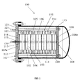
- an electrolyser 100 is set up by enclosing a cell stack item 101 in a pressure vessel 115, internally pressurised by a gas phase when in operation.
- the vessel is formed by a horizontal, cylindrical shell, with closed ends, one of which is a flanged cover, the second one a flanged cover, or an integral end, of flat or dished type.
- the preferred embodiment of the second end is a dished end, welded to the cylindrical shell.
- the material of construction of the vessel can be a metal, or a composite material, as for instance a fiber-reinforced manufacture.
- the cell stack 101 is formed by bipolar cells, each one comprising an anode 102 and a cathode 103, separated by a diaphragm or a membrane 104. In turn, each cell is separated from the next one by a bipolar plate 105.
- Cells have frames 106 containing channels 113 for the distribution of the electrolyte, and further channels 114 for the collection of the electrolysis products.
- a first terminal end plate 107a of the cell stack 101 is integral with an end plate cover of the pressure vessel, while the second end plate 108a of the cell stack 101 is movable inside the vessel, in a longitudinal direction relative to the plate 107a and the shell of the vessel 115, in response to thermal expansion and contraction.
- the end plate 107a forms a stationary head 107 of the cell stack 101
- the opposite end plate 108a forms a floating head 108 of the same cell stack.
- the stationary head 107 is equipped with the fluid connections for feeding an electrolyte to the cell stack, and for collecting the product(s) of the electrolysis, and is also equipped with anode and cathode electric connections with the cell stack.
- the anodic connection is given by a rod 120, passing through the plate 107a and electrically insulated with respect to said cover by a bush 119, carrying the anodic current directly to the first anode 117 of the stack 101.
- Said first anode 117 is electrically insulated from the plate 107a by an insulating plate 118.
- the rod 120 is provided with adequate gaskets, making it leak-tight with respect to the internal space under pressure.
- the end plate 108a is electrically in contact with the end cathode 116 of the stack 101, and is connected via tie rods 109 to the plate 107a. Hence, the plates 107a and 108a are equi-potential.
- the cathode terminal connection is also located directly on the plate 107a, in the form of a tie rod 121. By grounding this connection, the whole electrolyser is grounded, besides the only anodic connection 120, which can be easily protected from any contact with the operating personnel, thus making the design particularly safe.
- the vessel 115 is equi-potential with the cell stack plates 107a and 108a, due to the electrical connection given by tie rods 109.
- the only insulated connection to be passed from inside to outside of the electrolyser is the rod 120, in the example passing through the end cover of the vessel represented by the plate 107a.
- FIG. 120 A preferred embodiment of the anodic connection rod 120 is shown in further detail in Fig 2 .
- the tie rod 120 is welded to the first anode 117 of the stack, while at the opposite end it is threaded, and carries two washers 131 and two nuts 132, devised to fix the anodic electric cable.
- the electrically insulating, tubular bush 119 avoids the contact between the rod 120, under anodic polarisation, and the grounded plate 107.
- An insulating bush 125 and flat gaskets 126 separate the high-pressure space, acting on the outside diameter of said bush 125 and gaskets 126, from the low-pressure space, surrounding the rod 120.
- the two gaskets 126 are compressed between the bush 125 and the plate 107a and, respectively, between the bush 125 and the anode 117.
- a nut 130 draws the anode 117 against the plate 107a by means of the tie rod 120, cup springs 129, located between two washers 128, and an insulating bush 127.
- the space between the plate 107a and the anode 117 is occupied by an insulating plate 118.
- a material usable for the item 125 is, for instance, a glass-mica composite, while for the item 127 a mica-paper laminate material may be adequate.
- a port 123 is provided on the stationary head 107 for the pressurizing of the space internal to the pressure vessel 115, and external to the cell stack 101.
- this connection may be located at any place on the shell 115.
- the pressure internal to the vessel 115 has to be proportioned to the operating pressure inside the stack 101.
- the pressurizing medium is preferably a gas.
- the pressurising gas may be for instance nitrogen, or argon, or carbon dioxide, all extraneous to the electrolysis process.
- a source of one of such inert gases like a bottle, may be connected to the port 123, by means of a tubular connection, provided with a pressure reducer or controller.
- the gas pressurising the electrolyser jacket may be a gas product delivered by the electrolysis process, such as hydrogen or oxygen in the case of water electrolysis.
- Fig. 3 is an example of equipment for the electrolysis of water, comprising a gas-pressurized electrolyser 200 substantially realised as in Figs. 1-2 .
- the electrolyser 200 comprises a cell stack 210 inside a pressure vessel 220, and produces hydrogen and oxygen, which are delivered from the stationary head of the cell stack to the vessels V-1 and V-2, respectively, by pipes 201 and 202. Together with the gases some electrolyte is entrained and said vessels V-1 and V-2 have the duty of separating out the gases from the entrained liquid, which is returned to the electrolyser by pipes 203 and 204.
- Oxygen-side pressure inside the vessel V-2 is controlled by a differential pressure controller PDC, throttling a valve PDCV, so as to remain in the range of the hydrogen-side pressure.
- a line 208 connecting the line 206 to the pressure vessel 200, keeps the inside pressure of the vessel itself at a value controlled by the instrument PC-2 by throttling the valve PCV-02.
- the described embodiment can be reversed, by exchanging the role of the two gases, using then hydrogen as a pressurization means of the vessel 220.
- FIG 4 A further example is depicted in Fig 4 , corresponding to alternative control criteria of the electrolysis process.
- the vessels V-1 and V-2 are interconnected on the lower part by a pipe, so as to equalize the internal pressure of the two vessels, and consequently of the cathode and anodic compartments of the cells.
- hydrogen delivery pressure is controlled as in the previous case of Fig 3 .
- Oxygen delivery is controlled by keeping constant the electrolyte level inside V-2.
- the pressurisation of the vessel 220 is shown as made by hydrogen itself, through the loop PC-2/PCV-2, although it could be made by oxygen, as in the case of Fig 3 .
- Alternative control criteria may be selected by the skilled person.
- the invention reaches the aims and purposes stated above, and is particularly suitable for the production of high pressure hydrogen from the electrolysis of water.
Landscapes
- Chemical & Material Sciences (AREA)
- Engineering & Computer Science (AREA)
- Chemical Kinetics & Catalysis (AREA)
- Electrochemistry (AREA)
- Materials Engineering (AREA)
- Metallurgy (AREA)
- Organic Chemistry (AREA)
- Inorganic Chemistry (AREA)
- Electrolytic Production Of Non-Metals, Compounds, Apparatuses Therefor (AREA)
Claims (14)
- Elektrolyseapparat (100), umfassend:- einen Druckbehälter (115) mit einer Hülle und entgegengesetzten geschlossenen Enden;- einen Elektrolysezellenstapel (101) Innerhalb des Druckbehälters, der eine Vielzahl von bipolaren Elektrolysezellen umfasst, die zwischen einer ersten Abschlussendplatte (107a) und einer zweiten Abschlussendplatte (108a) angeordnet sind, wobei der Zellenstapel dazu eingerichtet Ist, unter Innendruck zu arbeiten;- Fluldanschlüsse zum Zuführen eines Elektrolyten zum Zellenstapel und Sammeln des Elektrolyseprodukts bzw. der Elektrolyseprodukte aus dem Zellenstapel, und elektrische Anschlüsse, die zumindest einen Anodenanschluss und einen Kathodenanschluss umfassen,
dadurch gekennzeichnet, dass
die erste Abschlussendplatte (107a) des Zellenstapels einstückig mit einem der geschlossenen Enden des Druckbehälters ist, wodurch ein stationärer Kopf (107) des Zellenstapels gebildet ist;
der stationäre Kopf (107) mit den Fluidanschlüssen (122) und mit elektrischen Anoden- und Kathodenanschlüssen (120, 121) zum zellenstapel ausgestattet ist;
die zweite Abschlussendplatte (108a) des Zellenstapels innerhalb des Druckbehälters (115) sitzt und sich in Antwort auf eine thermisch bedingte Ausdehnung oder Kontraktion frei In einer Längsrichtung relativ zur ersten Abschlussendplatte und zum Behälter bewegen kann, womit ein wandernder Kopf (108) des Zellenstapels gebildet ist. - Elektrolyseapparat nach Anspruch 1, wobei der Behälter (115) einen flachen Enddeckel (107a) aufweist, der auch die erste Abschlussendplatte des Zellenstapels (101) bildet.
- Elektrolyseapparat nach Anspruch 1 oder 2, wobei die elektrischen Anschlüsse umfassen: zumindest einen ersten elektrischen Verbinder (120), der durch die erste Abschlussendplatte (107a) des Zellenstapels (101) verläuft und gegenüber der Platte isoliert und elektrisch an die erste Zelle des Stapels angeschlossen ist; zumindest einen zweiten elektrischen Verbinder (121), der der ersten Abschlussendplatte zugeordnet und an diese elektrisch angeschlossen ist, wobei die erste Abschlussendplatte (107a) elektrisch an die zweite Abschlussendplatte (108a) des Stapels (101) angeschlossen ist.
- Elektrolyseapparat nach Anspruch 3, wobei die erste und zweite Abschlussendplatte des Zellenstapels durch Zugstäbe (109) zusammengesetzt sind, welche eine mechanische und elektrische Verbindung zwischen der ersten und zweiten Endplatte (107a, 108a) bereitstellen.
- Elektrolyseapparat nach Anspruch 3 oder 4, wobei der erste elektrische Verbinder (120) und/oder zweite elektrische Verbinder (121) mittels eines Zugstabs realisiert sind.
- Elektrolyseapparat nach einem der Ansprüche 3 bis 5, wobei der erste elektrische Verbinder (120) der positive Verbinder ist, der den anodischen Strom zur ersten Zelle des Zellenstapels (101) führt, und der zweite elektrische Verbinder (121) der negative Verbinder ist, dem somit die Aufgabe des Kathodenabschlusses für die letzte Zelle des Stapels zufällt.
- Elektrolyseapparat nach Anspruch 6, wobei der erste elektrische Verbinder (120) ein Zugstab Ist, der durch den stationären Kopf (107) des Zellenstapels (101) verläuft und gegenüber dem stationären Kopf durch eine rohrförmige Buchse (119) isoliert ist; der Zugstab (120) an der ersten Anode (117) des Zellenstapels (101) befestigt ist; eine Isolierplatte (118) zwischen der ersten Anode (117) und dem stationären Kopf (107) angeordnet ist; eine Isolierbuchse (125) und Dichtungen (126) vorgesehen sind, um den Zugstab vom Druckraum Innerhalb des Zellenstapels zu trennen.
- Elektrolyseverfahren, insbesondere zur Elektrolyse von Wasser, In einem Elektrolyseapparat nach einem der vorhergehenden Ansprüche, der einen Druckbehälter und einen Elektrolysezellenstapel innerhalb des Druckbehälters umfasst, wobei der Zellenstapel eine Vielzahl von bipolaren Elektrolysezellen aufweist, die zwischen einer ersten und einer zweiten Abschlussendplatte gestapelt sind, und dazu eingerichtet ist, unter Innendruck zu arbeiten, dadurch gekennzeichnet, dass der Behälter während des Betriebs des Zellenstapels durch ein gasförmiges Medium mit Druck beaufschlagt ist.
- Elektrolyseverfahren nach Anspruch 8, wobei das gasförmige Medium unter Druck in dem Zellenstapel hergestellt wird.
- Elektrolyseverfahren nach Anspruch 9, wobei der Druck In dem Zellenstapel größer als der Druckpegel in dem Behälter ist.
- Elektrolyseverfahren nach Anspruch 8 zur Elektrolyse von Wasser, wobei der Druck von durch den Zellenstapel geliefertem Wasserstoff größer als 30 bar Ist und vorzugsweise im Bereich von 100 bis 700 bar liegt.
- Anlage für die Elektrolyse, umfassend:- einen Elektrolyseapparat (200) nach einem der Ansprüche 1 bis 11, mit einem Zellenstapel (210) Innerhalb eines Druckbehälters (220), wobei der Zellenstapel dazu angepasst ist, zumindest ein Gasprodukt unter Druck zu liefern;- zumindest einen Behälter (V-1), der das Gasprodukt aufnimmt und dazu angepasst Ist, das Gasprodukt von mitgeführtem Elektrolyt zu trennen;- eine Strömungsleitung (208), die zumindest einen Teil des Gasprodukts als Druckbeaufschlagungsmedlum in den Druckbehälter (220) leitet.
- Anlage nach Anspruch 12 für die Elektrolyse von Wasser, wobei der Zellenstapel (210) dazu angepasst ist, Wasserstoff und Sauerstoff unter Druck zu liefern, umfassend- zumindest einen Behälter (V-1), der den Wasserstoff aufnimmt, und einen weiteren Behälter (V-2), der den Im Elektrolyseapparat (200) hergestellten Sauerstoff aufnimmt; wobei die Behälter dazu angepasst sind, den Wasserstoff und Sauerstoff jeweils von mitgeführtem Elektrolyt zu trennen;- eine Strömungsleitung (208), die zumindest einen Teil des Wasserstoffs oder einen Teil des Sauerstoffs als Druckbeaufschlagungsmedium von dem jeweiligen Behälter in den Druckbehälter (220) leitet.
- Verwendung eines Elektrolyseapparats oder einer Anlage nach den Ansprüchen 1 bis 7 bzw. 12 bis 13 zur Herstellung von Wasserstoff bei hohem Druck aus der Elektrolyse von Wasser.
Priority Applications (1)
| Application Number | Priority Date | Filing Date | Title |
|---|---|---|---|
| EP09783130.9A EP2340322B1 (de) | 2008-10-27 | 2009-09-17 | Hochdruckelektrolyseur |
Applications Claiming Priority (3)
| Application Number | Priority Date | Filing Date | Title |
|---|---|---|---|
| EP08018734A EP2180087A1 (de) | 2008-10-27 | 2008-10-27 | Hochdruckelektrolyseur |
| EP09783130.9A EP2340322B1 (de) | 2008-10-27 | 2009-09-17 | Hochdruckelektrolyseur |
| PCT/EP2009/062066 WO2010049214A1 (en) | 2008-10-27 | 2009-09-17 | High pressure electrolyser |
Publications (2)
| Publication Number | Publication Date |
|---|---|
| EP2340322A1 EP2340322A1 (de) | 2011-07-06 |
| EP2340322B1 true EP2340322B1 (de) | 2013-04-10 |
Family
ID=40433733
Family Applications (2)
| Application Number | Title | Priority Date | Filing Date |
|---|---|---|---|
| EP08018734A Withdrawn EP2180087A1 (de) | 2008-10-27 | 2008-10-27 | Hochdruckelektrolyseur |
| EP09783130.9A Active EP2340322B1 (de) | 2008-10-27 | 2009-09-17 | Hochdruckelektrolyseur |
Family Applications Before (1)
| Application Number | Title | Priority Date | Filing Date |
|---|---|---|---|
| EP08018734A Withdrawn EP2180087A1 (de) | 2008-10-27 | 2008-10-27 | Hochdruckelektrolyseur |
Country Status (10)
| Country | Link |
|---|---|
| US (1) | US8623195B2 (de) |
| EP (2) | EP2180087A1 (de) |
| JP (1) | JP5524227B2 (de) |
| CN (1) | CN102317505B (de) |
| CA (1) | CA2739019C (de) |
| DK (1) | DK2340322T3 (de) |
| ES (1) | ES2420982T3 (de) |
| PT (1) | PT2340322E (de) |
| RU (1) | RU2496918C2 (de) |
| WO (1) | WO2010049214A1 (de) |
Families Citing this family (34)
| Publication number | Priority date | Publication date | Assignee | Title |
|---|---|---|---|---|
| US20130140171A1 (en) * | 2008-07-15 | 2013-06-06 | Next Hydrogen Corporation | Electrolyser module |
| FR2957361B1 (fr) * | 2010-03-12 | 2012-04-20 | Commissariat Energie Atomique | Electrolyseur a haute temperature (eht) a surete de fonctionnement amelioree |
| EP2589426B1 (de) | 2011-11-02 | 2016-06-08 | Casale Sa | Verfahren zum entfernen von stickstoffoxiden aus verbrennungsabgasen mit ammoniakerzeugung vor ort |
| EP2617874B1 (de) * | 2012-01-18 | 2015-06-03 | H-TEC Systems GmbH | Elektrolyseur |
| CN104120441A (zh) * | 2014-07-11 | 2014-10-29 | 包秀敏 | 水解制氢双膜气体平衡装置 |
| CN104911626B (zh) * | 2015-06-23 | 2017-09-05 | 陕西华秦新能源科技有限责任公司 | 一种高压力水电解制氢电解槽 |
| CN105780044A (zh) * | 2016-04-21 | 2016-07-20 | 李兵 | 一种耐高压、防腐蚀的氢氧发生器 |
| CN106119886B (zh) * | 2016-06-23 | 2019-02-05 | 中国科学院过程工程研究所 | 一种加压电解槽及强化电解的方法 |
| DE102016007739A1 (de) * | 2016-06-27 | 2017-12-28 | Westfälische Hochschule Gelsenkirchen Bocholt Recklinghausen | Vorrichtung zur Energieumwandlung, insbesondere Brennstoffzelle oder Elektrolyseur |
| CN106801232A (zh) * | 2017-03-24 | 2017-06-06 | 陕西华秦新能源科技有限责任公司 | 一种水电解制氢电解装置及其方法 |
| RU174582U1 (ru) * | 2017-03-29 | 2017-10-23 | Федеральное государственное бюджетное учреждение "Национальный исследовательский центр "Курчатовский институт" | Электролизер высокого давления |
| JP7249588B2 (ja) * | 2018-06-14 | 2023-03-31 | パナソニックIpマネジメント株式会社 | 電気化学式水素ポンプ |
| FR3087953B1 (fr) | 2018-10-26 | 2021-07-02 | Commissariat Energie Atomique | Dispositif electrochimique comprenant un ensemble electrochimique dispose dans une enceinte de confinement |
| WO2020163513A1 (en) * | 2019-02-05 | 2020-08-13 | Arizona Board Of Regents On Behalf Of Arizona State University | System and method for production of synthetic fuel through co2 capture and water splitting |
| JP6826170B1 (ja) * | 2019-08-26 | 2021-02-03 | 株式会社日本トリム | 電解ユニット |
| CN111118522A (zh) * | 2020-02-16 | 2020-05-08 | 中科院大连化学物理研究所张家港产业技术研究院有限公司 | 罐式密封电解槽 |
| CN212511604U (zh) * | 2020-06-22 | 2021-02-09 | 江门市恒通高科有限公司 | 一种带电解杀菌模组的加湿器 |
| JP7398109B2 (ja) * | 2020-09-01 | 2023-12-14 | 守英 天白 | 水分解ガス発生装置の電極ユニット |
| DK181191B1 (en) * | 2021-01-22 | 2023-04-13 | Stiesdal Hydrogen As | An electrolysis system comprising a buffer tank |
| DK180996B1 (en) * | 2021-02-10 | 2022-09-12 | Stiesdal Hydrogen As | Hydrogen production plant and method of its operation |
| CN113249745A (zh) * | 2021-06-22 | 2021-08-13 | 黄天旗 | 顶丝反压式pem电解槽机构 |
| RU2771380C1 (ru) * | 2021-09-05 | 2022-05-04 | Сергей Станиславович Беднаржевский | Устройство для утилизации углекислого газа |
| EP4198172B1 (de) * | 2021-12-16 | 2026-03-25 | Abb Schweiz Ag | Anordnung eines alkalischen elektrolyseurs |
| CN114232011A (zh) * | 2021-12-28 | 2022-03-25 | 扬州乐道能源科技有限公司 | 一种电解槽 |
| JP2026512631A (ja) | 2022-10-25 | 2026-04-20 | カナデビア イノバ アクチェンゲゼルシャフト | 加圧電解槽、電解装置、及び電気分解方法 |
| DE102023000514B4 (de) | 2023-02-16 | 2025-10-30 | Bernd Heinisch | Hybridanlage zur Energiespeicherung mittels Batterien und Wasserstoff sowie Verfahren zum Betrieb der Anlage |
| DE102023203721A1 (de) * | 2023-04-24 | 2024-10-24 | Robert Bosch Gesellschaft mit beschränkter Haftung | Elektrochemischer Stack und Montageanordnung für einen solchen Stack |
| IT202300011013A1 (it) * | 2023-05-31 | 2024-12-01 | Arco Fc S R L | Sistema rigenerativo |
| IT202300018258A1 (it) | 2023-09-05 | 2025-03-05 | Leonardo Eng For Integration S R L | Cella elettrolitica con piatto bipolare multistrato e corpo isolante sagomato |
| DE102023213298A1 (de) * | 2023-12-22 | 2025-06-26 | Robert Bosch Gesellschaft mit beschränkter Haftung | Fluiddichter elektrochemischer Zellenstapel |
| DE102024113648B3 (de) | 2024-05-15 | 2025-05-15 | Forschungszentrum Jülich GmbH | Reaktor zur Durchführung von insbesondere exothermen Reaktionen sowie Verwendung und Verfahren zum Betreiben eines solchen Reaktors |
| DE102024113650B3 (de) | 2024-05-15 | 2025-05-15 | Forschungszentrum Jülich GmbH | Reaktor zur Durchführung von exothermen Reaktionen sowie Verwendung und Verfahren zum Betreiben eines solchen Reaktors |
| DE102024113652A1 (de) | 2024-05-15 | 2025-11-20 | Forschungszentrum Jülich GmbH | Vorrichtung zur Wärmeübertragung, Verwendung, Anlage und Verfahren |
| CN120330731A (zh) * | 2025-06-03 | 2025-07-18 | 深圳市雄韬电源科技股份有限公司 | 一种高压pem电解槽 |
Family Cites Families (17)
| Publication number | Priority date | Publication date | Assignee | Title |
|---|---|---|---|---|
| SU404062A1 (ru) * | 1971-08-17 | 1973-10-26 | Ордена Трудового Красного Знамени Институт горного дела А. А. Скочинского | УСТРОЙСТВО дл РЕГУЛИРОВАНИЯ ДАВЛЕНИЯ ГАЗОВ |
| SU487019A1 (ru) * | 1973-10-02 | 1975-10-05 | Институт проблем материаловедения АН УССР | Электролизер дл получени кислорода и водорода фильтрпрессного типа |
| CH672142A5 (de) | 1985-07-17 | 1989-10-31 | Metkon Sa | |
| CA2143446C (en) * | 1992-08-31 | 2004-08-17 | Neste Oy | Procedure for controlling pressure in electrolysis apparatus and electrolysis apparatus for producing hydrogen and oxygen |
| DE4418999C2 (de) | 1994-05-31 | 1996-04-11 | Von Hoerner System Gmbh | Druckelektrolyseur mit einem gekapselten Zellenblock aus einzelnen Elektrolysezellen |
| JP2911381B2 (ja) * | 1995-03-01 | 1999-06-23 | 神鋼パンテツク株式会社 | 水素・酸素発生装置 |
| JP3519529B2 (ja) * | 1995-12-27 | 2004-04-19 | 株式会社神鋼環境ソリューション | 水素・酸素発生装置 |
| TW347417B (en) * | 1996-05-08 | 1998-12-11 | Shinkohan Gigyutsu Kk | An apparatus for producing hydrogen and oxygen |
| DE29622000U1 (de) | 1996-12-19 | 1997-02-13 | Mtu Motoren- Und Turbinen-Union Friedrichshafen Gmbh, 88045 Friedrichshafen | Druckwassergekapselter Elektrolyseur |
| JP2000113995A (ja) * | 1998-02-25 | 2000-04-21 | Mitsubishi Electric Corp | 放電ランプ用点灯制御装置及び該装置に用いられるhブリッジ回路 |
| JP2001131787A (ja) * | 1999-10-29 | 2001-05-15 | Shinko Pantec Co Ltd | 電解セルの圧力補償構造 |
| DE10150557C2 (de) * | 2001-10-15 | 2003-12-18 | Mtu Friedrichshafen Gmbh | Druckelektrolyseur und Verfahren zum Betrieb eines solchen |
| EP1473386A4 (de) * | 2002-01-29 | 2005-04-06 | Mitsubishi Corp | Vorrichtung und verfahren zur erzeugung von hochdruckwasserstoff |
| DE10258525A1 (de) * | 2002-12-14 | 2004-07-01 | GHW Gesellschaft für Hochleistungselektrolyseure zur Wasserstofferzeugung mbH | Druckelektrolyseur und Verfahren zur Abschaltung eines Druckelektrolyseurs |
| JP4674659B2 (ja) * | 2004-11-04 | 2011-04-20 | 日立造船株式会社 | 水電解水素発生装置における容器収納型水電解装置 |
| DE102005011316B4 (de) * | 2005-03-11 | 2006-12-14 | Kaufmann, Hans, Dipl.-Ing. (FH) | Elektrolyseur und Verfahren zum Betrieb des Elektrolyseurs |
| JP4631525B2 (ja) * | 2005-04-27 | 2011-02-16 | 日立造船株式会社 | 容器収納型水電解槽の寸法変動吸収装置 |
-
2008
- 2008-10-27 EP EP08018734A patent/EP2180087A1/de not_active Withdrawn
-
2009
- 2009-09-17 RU RU2011120974/04A patent/RU2496918C2/ru active
- 2009-09-17 JP JP2011532557A patent/JP5524227B2/ja not_active Expired - Fee Related
- 2009-09-17 PT PT97831309T patent/PT2340322E/pt unknown
- 2009-09-17 EP EP09783130.9A patent/EP2340322B1/de active Active
- 2009-09-17 DK DK09783130.9T patent/DK2340322T3/da active
- 2009-09-17 ES ES09783130T patent/ES2420982T3/es active Active
- 2009-09-17 CN CN200980142704.XA patent/CN102317505B/zh not_active Expired - Fee Related
- 2009-09-17 US US13/125,123 patent/US8623195B2/en not_active Expired - Fee Related
- 2009-09-17 WO PCT/EP2009/062066 patent/WO2010049214A1/en not_active Ceased
- 2009-09-17 CA CA2739019A patent/CA2739019C/en active Active
Also Published As
| Publication number | Publication date |
|---|---|
| PT2340322E (pt) | 2013-07-15 |
| WO2010049214A1 (en) | 2010-05-06 |
| RU2496918C2 (ru) | 2013-10-27 |
| RU2011120974A (ru) | 2012-12-10 |
| DK2340322T3 (da) | 2013-07-08 |
| US20110210012A1 (en) | 2011-09-01 |
| ES2420982T3 (es) | 2013-08-28 |
| CA2739019A1 (en) | 2010-05-06 |
| US8623195B2 (en) | 2014-01-07 |
| JP2012506946A (ja) | 2012-03-22 |
| CA2739019C (en) | 2017-10-10 |
| CN102317505B (zh) | 2014-05-28 |
| EP2340322A1 (de) | 2011-07-06 |
| JP5524227B2 (ja) | 2014-06-18 |
| CN102317505A (zh) | 2012-01-11 |
| EP2180087A1 (de) | 2010-04-28 |
Similar Documents
| Publication | Publication Date | Title |
|---|---|---|
| CA2739019C (en) | High pressure electrolyser | |
| JP2012506946A5 (de) | ||
| US9133553B2 (en) | Externally-reinforced water electrolyzer module | |
| DK178317B1 (en) | Electrolyser Stack Divided into Sub-stacks | |
| WO2021029768A1 (en) | High-pressure electrolysis device | |
| DK178796B1 (en) | Pressurised Electrolysis Stack | |
| US10041178B2 (en) | End pressure plate for electrolysers | |
| NL2033845B1 (en) | Low-capacity high-pressure electrolysis device | |
| US20250034725A1 (en) | High-pressure electrolysis device | |
| KR100498234B1 (ko) | 전기화학적 수소-산소 발생 장치 | |
| EP4367291B1 (de) | Elektrolyseur mit mehrzelligen elementen |
Legal Events
| Date | Code | Title | Description |
|---|---|---|---|
| PUAI | Public reference made under article 153(3) epc to a published international application that has entered the european phase |
Free format text: ORIGINAL CODE: 0009012 |
|
| 17P | Request for examination filed |
Effective date: 20110301 |
|
| AK | Designated contracting states |
Kind code of ref document: A1 Designated state(s): AT BE BG CH CY CZ DE DK EE ES FI FR GB GR HR HU IE IS IT LI LT LU LV MC MK MT NL NO PL PT RO SE SI SK SM TR |
|
| AX | Request for extension of the european patent |
Extension state: AL BA RS |
|
| DAX | Request for extension of the european patent (deleted) | ||
| GRAP | Despatch of communication of intention to grant a patent |
Free format text: ORIGINAL CODE: EPIDOSNIGR1 |
|
| GRAS | Grant fee paid |
Free format text: ORIGINAL CODE: EPIDOSNIGR3 |
|
| GRAA | (expected) grant |
Free format text: ORIGINAL CODE: 0009210 |
|
| AK | Designated contracting states |
Kind code of ref document: B1 Designated state(s): AT BE BG CH CY CZ DE DK EE ES FI FR GB GR HR HU IE IS IT LI LT LU LV MC MK MT NL NO PL PT RO SE SI SK SM TR |
|
| REG | Reference to a national code |
Ref country code: GB Ref legal event code: FG4D |
|
| REG | Reference to a national code |
Ref country code: AT Ref legal event code: REF Ref document number: 606081 Country of ref document: AT Kind code of ref document: T Effective date: 20130415 Ref country code: CH Ref legal event code: EP |
|
| REG | Reference to a national code |
Ref country code: IE Ref legal event code: FG4D |
|
| REG | Reference to a national code |
Ref country code: CH Ref legal event code: NV Representative=s name: ING. MARCO ZARDI C/O M. ZARDI AND CO. S.A., CH |
|
| REG | Reference to a national code |
Ref country code: DE Ref legal event code: R096 Ref document number: 602009014920 Country of ref document: DE Effective date: 20130606 |
|
| REG | Reference to a national code |
Ref country code: SE Ref legal event code: TRGR |
|
| REG | Reference to a national code |
Ref country code: DK Ref legal event code: T3 |
|
| REG | Reference to a national code |
Ref country code: PT Ref legal event code: SC4A Free format text: AVAILABILITY OF NATIONAL TRANSLATION Effective date: 20130628 |
|
| REG | Reference to a national code |
Ref country code: NL Ref legal event code: T3 Ref country code: ES Ref legal event code: FG2A Ref document number: 2420982 Country of ref document: ES Kind code of ref document: T3 Effective date: 20130828 |
|
| PG25 | Lapsed in a contracting state [announced via postgrant information from national office to epo] |
Ref country code: SI Free format text: LAPSE BECAUSE OF FAILURE TO SUBMIT A TRANSLATION OF THE DESCRIPTION OR TO PAY THE FEE WITHIN THE PRESCRIBED TIME-LIMIT Effective date: 20130410 |
|
| REG | Reference to a national code |
Ref country code: LT Ref legal event code: MG4D |
|
| REG | Reference to a national code |
Ref country code: GR Ref legal event code: EP Ref document number: 20130401334 Country of ref document: GR Effective date: 20130829 |
|
| PG25 | Lapsed in a contracting state [announced via postgrant information from national office to epo] |
Ref country code: NO Free format text: LAPSE BECAUSE OF FAILURE TO SUBMIT A TRANSLATION OF THE DESCRIPTION OR TO PAY THE FEE WITHIN THE PRESCRIBED TIME-LIMIT Effective date: 20130710 Ref country code: IS Free format text: LAPSE BECAUSE OF FAILURE TO SUBMIT A TRANSLATION OF THE DESCRIPTION OR TO PAY THE FEE WITHIN THE PRESCRIBED TIME-LIMIT Effective date: 20130810 Ref country code: LT Free format text: LAPSE BECAUSE OF FAILURE TO SUBMIT A TRANSLATION OF THE DESCRIPTION OR TO PAY THE FEE WITHIN THE PRESCRIBED TIME-LIMIT Effective date: 20130410 |
|
| PG25 | Lapsed in a contracting state [announced via postgrant information from national office to epo] |
Ref country code: CY Free format text: LAPSE BECAUSE OF FAILURE TO SUBMIT A TRANSLATION OF THE DESCRIPTION OR TO PAY THE FEE WITHIN THE PRESCRIBED TIME-LIMIT Effective date: 20130410 Ref country code: HR Free format text: LAPSE BECAUSE OF FAILURE TO SUBMIT A TRANSLATION OF THE DESCRIPTION OR TO PAY THE FEE WITHIN THE PRESCRIBED TIME-LIMIT Effective date: 20130410 Ref country code: LV Free format text: LAPSE BECAUSE OF FAILURE TO SUBMIT A TRANSLATION OF THE DESCRIPTION OR TO PAY THE FEE WITHIN THE PRESCRIBED TIME-LIMIT Effective date: 20130410 Ref country code: BG Free format text: LAPSE BECAUSE OF FAILURE TO SUBMIT A TRANSLATION OF THE DESCRIPTION OR TO PAY THE FEE WITHIN THE PRESCRIBED TIME-LIMIT Effective date: 20130710 Ref country code: PL Free format text: LAPSE BECAUSE OF FAILURE TO SUBMIT A TRANSLATION OF THE DESCRIPTION OR TO PAY THE FEE WITHIN THE PRESCRIBED TIME-LIMIT Effective date: 20130410 |
|
| PG25 | Lapsed in a contracting state [announced via postgrant information from national office to epo] |
Ref country code: SK Free format text: LAPSE BECAUSE OF FAILURE TO SUBMIT A TRANSLATION OF THE DESCRIPTION OR TO PAY THE FEE WITHIN THE PRESCRIBED TIME-LIMIT Effective date: 20130410 Ref country code: EE Free format text: LAPSE BECAUSE OF FAILURE TO SUBMIT A TRANSLATION OF THE DESCRIPTION OR TO PAY THE FEE WITHIN THE PRESCRIBED TIME-LIMIT Effective date: 20130410 Ref country code: CZ Free format text: LAPSE BECAUSE OF FAILURE TO SUBMIT A TRANSLATION OF THE DESCRIPTION OR TO PAY THE FEE WITHIN THE PRESCRIBED TIME-LIMIT Effective date: 20130410 |
|
| PLBE | No opposition filed within time limit |
Free format text: ORIGINAL CODE: 0009261 |
|
| STAA | Information on the status of an ep patent application or granted ep patent |
Free format text: STATUS: NO OPPOSITION FILED WITHIN TIME LIMIT |
|
| PG25 | Lapsed in a contracting state [announced via postgrant information from national office to epo] |
Ref country code: RO Free format text: LAPSE BECAUSE OF FAILURE TO SUBMIT A TRANSLATION OF THE DESCRIPTION OR TO PAY THE FEE WITHIN THE PRESCRIBED TIME-LIMIT Effective date: 20130410 |
|
| 26N | No opposition filed |
Effective date: 20140113 |
|
| REG | Reference to a national code |
Ref country code: DE Ref legal event code: R097 Ref document number: 602009014920 Country of ref document: DE Effective date: 20140113 |
|
| PG25 | Lapsed in a contracting state [announced via postgrant information from national office to epo] |
Ref country code: MC Free format text: LAPSE BECAUSE OF FAILURE TO SUBMIT A TRANSLATION OF THE DESCRIPTION OR TO PAY THE FEE WITHIN THE PRESCRIBED TIME-LIMIT Effective date: 20130410 |
|
| PG25 | Lapsed in a contracting state [announced via postgrant information from national office to epo] |
Ref country code: SM Free format text: LAPSE BECAUSE OF FAILURE TO SUBMIT A TRANSLATION OF THE DESCRIPTION OR TO PAY THE FEE WITHIN THE PRESCRIBED TIME-LIMIT Effective date: 20130410 |
|
| PG25 | Lapsed in a contracting state [announced via postgrant information from national office to epo] |
Ref country code: MT Free format text: LAPSE BECAUSE OF FAILURE TO SUBMIT A TRANSLATION OF THE DESCRIPTION OR TO PAY THE FEE WITHIN THE PRESCRIBED TIME-LIMIT Effective date: 20130410 |
|
| PG25 | Lapsed in a contracting state [announced via postgrant information from national office to epo] |
Ref country code: MK Free format text: LAPSE BECAUSE OF FAILURE TO SUBMIT A TRANSLATION OF THE DESCRIPTION OR TO PAY THE FEE WITHIN THE PRESCRIBED TIME-LIMIT Effective date: 20130410 Ref country code: HU Free format text: LAPSE BECAUSE OF FAILURE TO SUBMIT A TRANSLATION OF THE DESCRIPTION OR TO PAY THE FEE WITHIN THE PRESCRIBED TIME-LIMIT; INVALID AB INITIO Effective date: 20090917 Ref country code: LU Free format text: LAPSE BECAUSE OF NON-PAYMENT OF DUE FEES Effective date: 20130917 |
|
| REG | Reference to a national code |
Ref country code: FR Ref legal event code: PLFP Year of fee payment: 8 |
|
| REG | Reference to a national code |
Ref country code: FR Ref legal event code: PLFP Year of fee payment: 9 |
|
| REG | Reference to a national code |
Ref country code: FR Ref legal event code: PLFP Year of fee payment: 10 |
|
| REG | Reference to a national code |
Ref country code: DE Ref legal event code: R079 Ref document number: 602009014920 Country of ref document: DE Free format text: PREVIOUS MAIN CLASS: C25B0001120000 Ipc: C25B0001040000 |
|
| P01 | Opt-out of the competence of the unified patent court (upc) registered |
Effective date: 20230527 |
|
| PGFP | Annual fee paid to national office [announced via postgrant information from national office to epo] |
Ref country code: NL Payment date: 20230822 Year of fee payment: 15 |
|
| PGFP | Annual fee paid to national office [announced via postgrant information from national office to epo] |
Ref country code: TR Payment date: 20230823 Year of fee payment: 15 Ref country code: IT Payment date: 20230822 Year of fee payment: 15 Ref country code: IE Payment date: 20230823 Year of fee payment: 15 Ref country code: GB Payment date: 20230823 Year of fee payment: 15 Ref country code: FI Payment date: 20230823 Year of fee payment: 15 Ref country code: AT Payment date: 20230823 Year of fee payment: 15 |
|
| PGFP | Annual fee paid to national office [announced via postgrant information from national office to epo] |
Ref country code: SE Payment date: 20230822 Year of fee payment: 15 Ref country code: PT Payment date: 20230823 Year of fee payment: 15 Ref country code: GR Payment date: 20230823 Year of fee payment: 15 Ref country code: FR Payment date: 20230822 Year of fee payment: 15 Ref country code: DK Payment date: 20230822 Year of fee payment: 15 Ref country code: DE Payment date: 20230822 Year of fee payment: 15 Ref country code: BE Payment date: 20230822 Year of fee payment: 15 |
|
| PGFP | Annual fee paid to national office [announced via postgrant information from national office to epo] |
Ref country code: ES Payment date: 20231002 Year of fee payment: 15 |
|
| PGFP | Annual fee paid to national office [announced via postgrant information from national office to epo] |
Ref country code: CH Payment date: 20231001 Year of fee payment: 15 |
|
| REG | Reference to a national code |
Ref country code: DE Ref legal event code: R119 Ref document number: 602009014920 Country of ref document: DE |
|
| PG25 | Lapsed in a contracting state [announced via postgrant information from national office to epo] |
Ref country code: PT Free format text: LAPSE BECAUSE OF NON-PAYMENT OF DUE FEES Effective date: 20250317 |
|
| PG25 | Lapsed in a contracting state [announced via postgrant information from national office to epo] |
Ref country code: FI Free format text: LAPSE BECAUSE OF NON-PAYMENT OF DUE FEES Effective date: 20240917 |
|
| REG | Reference to a national code |
Ref country code: DK Ref legal event code: EBP Effective date: 20240930 |
|
| REG | Reference to a national code |
Ref country code: SE Ref legal event code: EUG |
|
| REG | Reference to a national code |
Ref country code: CH Ref legal event code: PL |
|
| REG | Reference to a national code |
Ref country code: NL Ref legal event code: MM Effective date: 20241001 |
|
| REG | Reference to a national code |
Ref country code: AT Ref legal event code: MM01 Ref document number: 606081 Country of ref document: AT Kind code of ref document: T Effective date: 20240917 |
|
| GBPC | Gb: european patent ceased through non-payment of renewal fee |
Effective date: 20240917 |
|
| PG25 | Lapsed in a contracting state [announced via postgrant information from national office to epo] |
Ref country code: NL Free format text: LAPSE BECAUSE OF NON-PAYMENT OF DUE FEES Effective date: 20241001 |
|
| PG25 | Lapsed in a contracting state [announced via postgrant information from national office to epo] |
Ref country code: DE Free format text: LAPSE BECAUSE OF NON-PAYMENT OF DUE FEES Effective date: 20250401 |
|
| PG25 | Lapsed in a contracting state [announced via postgrant information from national office to epo] |
Ref country code: GB Free format text: LAPSE BECAUSE OF NON-PAYMENT OF DUE FEES Effective date: 20240917 |
|
| REG | Reference to a national code |
Ref country code: BE Ref legal event code: MM Effective date: 20240930 |
|
| PG25 | Lapsed in a contracting state [announced via postgrant information from national office to epo] |
Ref country code: IT Free format text: LAPSE BECAUSE OF NON-PAYMENT OF DUE FEES Effective date: 20240917 Ref country code: BE Free format text: LAPSE BECAUSE OF NON-PAYMENT OF DUE FEES Effective date: 20240930 |
|
| PG25 | Lapsed in a contracting state [announced via postgrant information from national office to epo] |
Ref country code: FR Free format text: LAPSE BECAUSE OF NON-PAYMENT OF DUE FEES Effective date: 20240930 |
|
| PG25 | Lapsed in a contracting state [announced via postgrant information from national office to epo] |
Ref country code: GR Free format text: LAPSE BECAUSE OF NON-PAYMENT OF DUE FEES Effective date: 20250407 |
|
| PG25 | Lapsed in a contracting state [announced via postgrant information from national office to epo] |
Ref country code: CH Free format text: LAPSE BECAUSE OF NON-PAYMENT OF DUE FEES Effective date: 20240930 |
|
| PG25 | Lapsed in a contracting state [announced via postgrant information from national office to epo] |
Ref country code: AT Free format text: LAPSE BECAUSE OF NON-PAYMENT OF DUE FEES Effective date: 20240917 |
|
| PG25 | Lapsed in a contracting state [announced via postgrant information from national office to epo] |
Ref country code: IE Free format text: LAPSE BECAUSE OF NON-PAYMENT OF DUE FEES Effective date: 20240917 |
|
| PG25 | Lapsed in a contracting state [announced via postgrant information from national office to epo] |
Ref country code: DK Free format text: LAPSE BECAUSE OF NON-PAYMENT OF DUE FEES Effective date: 20240930 |
|
| PG25 | Lapsed in a contracting state [announced via postgrant information from national office to epo] |
Ref country code: SE Free format text: LAPSE BECAUSE OF NON-PAYMENT OF DUE FEES Effective date: 20240918 |
|
| REG | Reference to a national code |
Ref country code: ES Ref legal event code: FD2A Effective date: 20251031 |
|
| PG25 | Lapsed in a contracting state [announced via postgrant information from national office to epo] |
Ref country code: ES Free format text: LAPSE BECAUSE OF NON-PAYMENT OF DUE FEES Effective date: 20240918 |