EP2339805B1 - Appareil de réception, procédé de réception, programme et système de réception - Google Patents
Appareil de réception, procédé de réception, programme et système de réception Download PDFInfo
- Publication number
- EP2339805B1 EP2339805B1 EP10194977.4A EP10194977A EP2339805B1 EP 2339805 B1 EP2339805 B1 EP 2339805B1 EP 10194977 A EP10194977 A EP 10194977A EP 2339805 B1 EP2339805 B1 EP 2339805B1
- Authority
- EP
- European Patent Office
- Prior art keywords
- plp
- common
- decoding information
- data packet
- packet sequences
- Prior art date
- Legal status (The legal status is an assumption and is not a legal conclusion. Google has not performed a legal analysis and makes no representation as to the accuracy of the status listed.)
- Active
Links
- 238000000034 method Methods 0.000 title claims description 276
- 230000006870 function Effects 0.000 claims description 3
- NGVDGCNFYWLIFO-UHFFFAOYSA-N pyridoxal 5'-phosphate Chemical compound CC1=NC=C(COP(O)(O)=O)C(C=O)=C1O NGVDGCNFYWLIFO-UHFFFAOYSA-N 0.000 claims 2
- 230000008569 process Effects 0.000 description 249
- 230000005540 biological transmission Effects 0.000 description 52
- 230000011664 signaling Effects 0.000 description 16
- 238000010586 diagram Methods 0.000 description 8
- 238000012937 correction Methods 0.000 description 7
- 102220474389 Retinoic acid receptor RXR-alpha_S27A_mutation Human genes 0.000 description 5
- 238000004891 communication Methods 0.000 description 4
- 230000006837 decompression Effects 0.000 description 3
- 230000015654 memory Effects 0.000 description 3
- 230000000717 retained effect Effects 0.000 description 3
- 230000000694 effects Effects 0.000 description 2
- 230000003287 optical effect Effects 0.000 description 2
- 238000012545 processing Methods 0.000 description 2
- 230000001133 acceleration Effects 0.000 description 1
- 230000004075 alteration Effects 0.000 description 1
- 238000013459 approach Methods 0.000 description 1
- 230000006835 compression Effects 0.000 description 1
- 238000007906 compression Methods 0.000 description 1
- 238000013461 design Methods 0.000 description 1
- 238000012986 modification Methods 0.000 description 1
- 230000004048 modification Effects 0.000 description 1
- 230000010363 phase shift Effects 0.000 description 1
- 230000004044 response Effects 0.000 description 1
- 239000004065 semiconductor Substances 0.000 description 1
Images


Classifications
-
- H—ELECTRICITY
- H04—ELECTRIC COMMUNICATION TECHNIQUE
- H04L—TRANSMISSION OF DIGITAL INFORMATION, e.g. TELEGRAPHIC COMMUNICATION
- H04L27/00—Modulated-carrier systems
- H04L27/26—Systems using multi-frequency codes
- H04L27/2601—Multicarrier modulation systems
- H04L27/2647—Arrangements specific to the receiver only
Definitions
- the present invention relates to a reception apparatus, a reception method, a program, and a reception system. More particularly, the invention relates to a reception apparatus, a reception method, a program, and a reception system for performing decoding processes faster than before.
- OFDM Orthogonal Frequency Division Multiplexing
- PSK Phase Shift Keying
- QAM Quadrature Amplitude Modulation
- the OFDM method is often applied to terrestrial digital broadcasts that are highly vulnerable to multi-pass interference.
- the terrestrial digital broadcasts adopting the OFDM method typically comply with such standards as DVB-T (Digital Video Broadcasting-Terrestrial) and ISDB-T (Integrated Services Digital Broadcasting-Terrestrial).
- DVB-T Digital Video Broadcasting-Terrestrial
- ISDB-T Integrated Services Digital Broadcasting-Terrestrial
- DVB-T2 Digital Video Broadcasting-Terrestrial 2; second generation digital terrestrial television broadcasting system
- DVB-T2 Digital Video Broadcasting-Terrestrial 2; second generation digital terrestrial television broadcasting system
- DVB-T2 is described illustratively in the so-called Bluebook (DVB Bluebook A122, "Frame structure channel coding and modulation for a second generation digital terrestrial television broadcasting system (DVB-T2)," DVB Document A122 June 2008, called the Non-patent Document 1 hereunder).
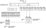
- T2 frame Under DVB-T2 (i.e., as stipulated in the Bluebook), frames each called a T2 frame are defined. Data is transmitted in units of a T2 frame.
- the T2 frame has two preamble signals called P1 and P2. These preamble signals include information necessary for processing the OFDM signal illustratively such as through decoding.
- Fig. 1 is a schematic view showing the format of the T2 frame.
- the T2 format includes a P1 symbol, a P2 symbol, and data symbols, in that order.
- the P1 symbol is a symbol for transmitting P1 signaling that includes a transmission type and basic transmission parameters.
- the P1 signaling includes parameters S1 and S2.
- the parameters S1 and S2 indicate a P2 transmission type (i.e., whether P2 is transmitted in SISO (Single Input Single Output) fashion (using one transmitting antenna and one receiving antenna) or in MISO (Multiple Input Single Output) fashion (using multiple transmitting antennas but one receiving antenna)), and an FFT size for performing FFT computation of P2 (i.e., number of samples (symbols) subject to one FFT computation). It follows that to demodulate the P2 symbol requires demodulating the P1 symbol first.
- the P2 symbol is a symbol for transmitting L1 pre-signaling and L1 post-signaling.
- the L1 pre-signaling includes information used by a reception apparatus receiving T2 frames for receiving and decoding the L1 post-signaling.
- the L1 post-signaling includes parameters needed by the reception apparatus for accessing the physical layer (i.e., its layer pipes).
- DVB-T2 adopts a method called M-PLP (Multiple PLP (Physical Layer Pipe)).
- M-PLP Multiple PLP (Physical Layer Pipe)
- data is transmitted using packet sequences (data packet sequences) constituted by a plurality of Data PLP's composed of the packets left behind after extracting from a plurality of original transport streams (TS's) those packets (information) common to all TS's, and packet sequences (common packet sequences) called Common PLP's constituted by the packets common to the TS's.
- a Common PLP is composed of packets common to a plurality of TS's
- a Data PLP is constituted by packets unique to each of a plurality of TS's.
- a single original TS is restored from a Common PLP and Data PLP's.
- a Data PLP is a unit of service information, and a Common PLP is a portion common to at least two Data PLP's. Thus there exists the following relationship: Data PLP count ⁇ 2 ⁇ Common PLP count ⁇ 0
- a plurality of Data PLP's are combined with a single Common PLP. At least two Data PLP's exist with regard to a given Common PLP, and there is one Common PLP for a given Data PLP.
- To decode one unit of service information requires decoding two PLP's (a Common PLP and a Data PLP) simultaneously.
- the decoding information necessary for decoding the Common PLP and Data PLP (the information is called PLP information hereunder) is included in the L1 post-signaling.
- PLP information made up of a Common PLP and Data PLP's corresponding to the service information desired to be decoded needs to be extracted from the L1 post-signaling.
- a plurality of units of PLP information are arranged in order of their PLPID's within the L1 post-signaling.
- Each unit of PLP information contains a PLPID for uniquely identifying each PLP, a PLP type for indicating whether this PLP is a Data PLP or a Common PLP, a GroupID for uniquely identifying the corresponding Common PLP and Data PLP, and PLP transmission parameter information.
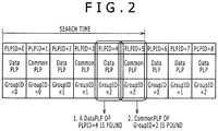
- a search is made for the PLP information composed of a Common PLP and Data PLP's corresponding to the target service information (this process is called the PLP search process).
- the PLP search process is completed within one T2 frame in the case of Fig. 2
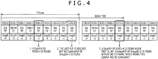
- the process does not end within one T2 frame in the cases of Figs. 3 and 4 . Since the PLP search process needs to be continued into the next T2 frame, it takes longer to make the search in the cases of Figs. 3 and 4 than in the case of Fig. 2 .
- WO2007/137276 describes a wireless communication system in which pilots are transmitted for signal acquisition.
- One pilot may be common to all access points in the system and used to provide general timing information for the system, while other pilots may be unique to each access point and used to provide more accurate timing for the access point.
- the present invention has been made in view of the above circumstances and provides among others a reception apparatus that performs PLP search processes rapidly for fast decoding when receiving signals transmitted in such a manner that a plurality of methods are multiplexed therein.
- a reception apparatus including: reception means for receiving an orthogonal frequency division multiplexing signal known as an OFDM signal formed by modulating common packet sequences and data packet sequences, the common packet sequences being made up of packets common to a plurality of streams, the data packet sequences being constituted by packets unique to each of the plurality of streams; acquisition means for acquiring decoding information for decoding the original streams from the common packet sequences and the data packet sequences obtained by demodulating the received OFDM signal; and search means for searching for the common packet sequence needed to decode the original streams from the designated data packet sequence on the basis of the acquired decoding information.
- reception means for receiving an orthogonal frequency division multiplexing signal known as an OFDM signal formed by modulating common packet sequences and data packet sequences, the common packet sequences being made up of packets common to a plurality of streams, the data packet sequences being constituted by packets unique to each of the plurality of streams
- acquisition means for acquiring decoding information for decoding the original streams from the common packet sequences and the data packet sequence
- the reception apparatus includes storage means for storing the decoding information about the acquired common packet sequence until the decoding information about the designated data packet sequence is acquired; wherein, when the decoding information about the designated data packet sequence is acquired, the search means may search the stored decoding information about the common packet sequences for the decoding information identified by the decoding information about the acquired data packet sequences.
- the search means may search for the decoding information identified by the decoding information about the acquired data packet sequences out of that decoding information about the common packet sequences which is acquired following the acquisition of the decoding information about the designated data packet sequence.
- the search means may search for the predetermined number of units of the decoding information about the common packet sequences which are identified by the decoding information about the designated data packet sequence.
- the storage means may be made up of as many as n registers, the number n satisfying a relationship of 1 ⁇ n ⁇ m where m represents a maximum number of units of the decoding information about the common packet sequences; and if the decoding information about the common packet sequences cannot be identified from within a first frame targeted for the search, then the search means may search through a second frame next to the first frame.
- the search means may search for the predetermined number of units of the decoding information about the common packet sequences which are identified by the decoding information about the designated data packet sequence.
- the decoding information may include at least a first and a second identifier, the first identifier identifying each packet sequence, the second identifier distinguishing the corresponding common packet sequence from the data packet sequences; and the search means may identify the decoding information about the data packet sequence having the designated first identifier, before identifying the decoding information about the common packet sequence having the second identifier included in the decoding information about the designated data packet sequence.
- the reception apparatus may further include decoding means for decoding the original streams from the common packet sequences and the data packet sequences based on a result of the search made by the search means.
- the common packet sequences and the data packet sequences may be constituted, respectively, by Common PLP's which stand for common physical pipe layers and by Data PLP's which stand for data physical pipe layers generated from a plurality of original streams according to an M-PLP method which stands for a multiple physical layer pipe method under DVB-T2.
- a reception method for causing a reception apparatus to execute a procedure including the steps of: receiving an orthogonal frequency division multiplexing signal known as an OFDM signal formed by modulating common packet sequences and data packet sequences, the common packet sequences being made up of packets common to a plurality of streams, the data packet sequences being constituted by packets unique to each of the plurality of streams; acquiring decoding information for decoding the original streams from the common packet sequences and the data packet sequences obtained by demodulating the received OFDM signal; and searching for the common packet sequence needed to decode the original streams from the designated data packet sequence on the basis of the acquired decoding information, further comprising the step of storing the decoding information about the acquired common packet sequence until the decoding information about said designated data packet sequence is acquired; wherein, when the decoding information about said designated data packet sequences is acquired, the step of searching for the common packet sequence needed to decode the original streams from the designated data packet sequence on the bases of the acquired decoding information comprises: searching the stored
- a program for causing a computer to implement the functions including: reception means for receiving an orthogonal frequency division multiplexing signal known as an OFDM signal formed by modulating common packet sequences and data packet sequences, the common packet sequences being made up of packets common to a plurality of streams, the data packet sequences being constituted by packets unique to each of the plurality of streams; acquisition means for acquiring decoding information for decoding the original streams from the common packet sequences and the data packet sequences obtained by demodulating the received OFDM signal; and search means for searching for the common packet sequence needed to decode the original streams from the designated data packet sequence on the basis of the acquired decoding information, further comprising a storage means for storing the decoding information about the acquired common packet sequence until the decoding information about said designated data packet sequence is acquired; wherein, when the decoding information about said designated data packet sequence is acquired, said search means searches the stored decoding information about said common packet sequences for the decoding information identified by the decoding information about the acquired data
- an orthogonal frequency division multiplexing signal known as an OFDM signal formed by modulating common packet sequences and data packet sequences is received.
- the common packet sequences are each made up of packets common to a plurality of streams, and the data packet sequences are each constituted by packets unique to each of the plurality of streams.
- Decoding information for decoding the original streams is then acquired from the common packet sequences and the data packet sequences obtained by demodulating the received OFDM signal. And a search is made for the common packet sequence needed to decode the original streams from the designated data packet sequence on the basis of the acquired decoding information.
- the decoding process is performed appreciably faster than before.
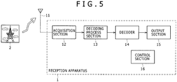
- Fig. 5 is a block diagram showing a typical structure of a reception apparatus 1 embodying the present invention.
- the reception system 1 receives a digital broadcast signal sent from a transmission apparatus 2.
- This signal is an OFDM signal (received signal) obtained by performing such processes as error correction and OFDM modulation on the PLP's (physical layer pipes) generated from transport streams (TS's) according to the M-PLP method under DVB-T2 being worked out as a standard for second generation digital terrestrial television broadcasting.
- OFDM signal received signal obtained by performing such processes as error correction and OFDM modulation on the PLP's (physical layer pipes) generated from transport streams (TS's) according to the M-PLP method under DVB-T2 being worked out as a standard for second generation digital terrestrial television broadcasting.
- the transmission apparatus 2 such as a broadcasting station transmits the received signal of a digital broadcast via a transmission channel.
- the reception system 1 acquires the received signal sent from the transmission apparatus 2, performs a decoding process including demodulation and error correction on the received signal, and outputs decoding data resulting from the process to the downstream stage.
- the reception apparatus 1 is made up of an antenna 11, an acquisition section 12, a decoding process section 13, a decoder 14, an output section 15, and a control section 16.
- the antenna 11 captures the received signal sent from the transmission apparatus 2 over the transmission channel.
- the received signal is fed to the acquisition section 12.
- the acquisition section 12 is illustratively composed of a tuner or a set-top box (STB).
- the acquisition section 12 frequency-converts the received signal (RF signal) coming from the antenna 11 into an IF (intermediate frequency) signal.
- the resulting IF signal is forwarded to the decoding process section 13.
- the decoding process section 13 decodes the received signal coming from the acquisition section 12 into PLP's through such necessary processes as demodulation and error correction. From the PLP's, the decoding process section 13 restores TS's and feeds them to the decoder 14.
- the decoding process section 13 acquires desired Data PLP's and one Common PLP appended to the Data PLP's from the demodulated signal which is obtained by demodulating the received signal. A predetermined error correction process is performed on these PLP's.
- the transmission apparatus 2 encodes program data such as images and sounds using the MPEG (Moving Picture Experts Group) standard into MPEG-encoded data.
- the MPEG-encoded data is placed in TS packets making up transport streams (TS's) that are turned into PLP's.
- the transmission apparatus 2 transmits the PLP's thus generated as the received signal.
- the transmission apparatus 2 encodes the PLP's illustratively using the RS (Reed Solomon) code or LDPC (Low Density Parity Check) code.
- the decoding process section 13 decodes the encoded data as part of its error correction process.
- the decoding process section 13 proceeds to restore the TS's from the decoded PLP's and supplies the result of the decoding to the decoder 14.
- the decoder 14 decodes the encoded data contained in the TS's coming from the decoding process section 13 as per the MPEG standard.
- the data made up of the resulting images and sounds is fed to the output section 15.
- the output section 15 is typically composed of a display and speakers. Given the image and sound data from the decoder 14, the output section 15 displays images and outputs sounds accordingly.
- the control section 16 controls the components of the reception apparatus 1 including the decoding process section 13. A first and a second PLP search process to be carried out by the control section 16 will be discussed later in detail. The foregoing paragraphs have explained the typical structure of the reception apparatus 1.
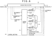
- Fig. 6 is a block diagram showing a detailed structure of the control section 16 included in Fig. 5 .
- the control section 16 controls the decoding process section 13 performing the decoding process.
- the control circuit 31 is supplied with a PLP information signal, a designated PLPID signal, and a T2 frame start signal (these signals are called the input signals collectively) from the decoding process section 13 in a suitably timed manner.
- the decoding process section 13 upon detecting the start of a T2 frame from the received signal, the decoding process section 13 generates a T2 frame start signal.
- the T2 frame start signal allows the control circuit 31 to determine the start position of a given T2 frame.
- the decoding process section 13 when the user designates desired service information, the decoding process section 13 generates a designated PLPID signal corresponding to the desired service information and feeds the generated PLPID signal to the control circuit 31.
- the decoding process section 13 demodulates P1 signaling from the T2 frame in which a P1 symbol is first detected. Then the demodulation section 21 carries out predetermined computations on a P2 symbol. When it becomes possible to demodulate the L1 pre-signaling included in the P2 symbol, data demodulation is made possible thereafter. This in turn makes it possible to extract PLP information from the L1 post-signaling, so that the decoding process section 13 generates the PLP information signal and feeds the generated signal to the control circuit 31.
- the control circuit 31 sends to the register 32 a PLP information signal indicating the PLP type to be "data" from among the PLP information signals corresponding to the PLP information acquired from a given T2 frame.
- the control circuit 31 further supplies a PLP information signal indicating the PLP type to be "common” to one of the registers 33 1 through 33 n .
- control circuit 31 identifies a Data PLP having a PLPID corresponding to the designated PLPID signal, and supplies the selector 34 with a signal for selecting the PLP information signal of the Common PLP appended to the identified Data PLP (the supplied signal is called the Common PLP selection signal hereunder). If there is no Common PLP appended to the Data PLP, then the control circuit 31 supplies the decoding process section 13 with a signal indicating the absence of a Common PLP (the signal is called the no-common signal hereunder). Furthermore, if there is no Data PLP having the PLPID corresponding to the designated PLPID signal, the control circuit 31 supplies the decoding process section 13 with a signal indicating the absence of the Data PLP (the signal is called the no-data signal hereunder).
- the register 32 acquires and stores (i.e., holds) the PLP information signal which is fed from the control circuit 31 and which indicates the PLP type to be "data.” Upon request from the control circuit 31, the register 32 supplies the control circuit 31 with a GroupID signal from among the PLP information signals held therein. The register 32 further feeds the PLP information signals held therein to the decoding process section 13.
- the registers 33 1 through 33 n Upon request from the control circuit 31, the registers 33 1 through 33 n supply the control circuit 31 with a GroupID signal from among the stored PLP information signals. The registers 33 1 through 33 n also feed the stored PLP information signals to the selector 34.
- the selector 34 Based on the Common PLP selection signal coming from the control circuit 31, the selector 34 selects one of the PLP information signals of the Common PLP's from among those stored in the registers 33 1 through 33 n .
- the selected PLP information signal is sent to the decoding process section 13.
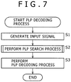
- the PLP decoding process carried out by the decoding process section 13 and control section 16 is explained below by reference to the flowchart of Fig. 7 .
- the antenna 11 captures the received signal sent from the transmission apparatus 2 and forwards the received signal to the acquisition section 12.
- the acquisition section 12 frequency-converts the received signal (RF signal) coming from the antenna 11 into an IF signal and sends the IF signal to the decoding process section 13.
- step S1 the decoding process section 13 generates a T2 frame start signal, a PLP information signal, or a designated PLP signal (i.e., input signal) from the received signal coming from the acquisition section 12.
- the input signal thus generated is fed to the control section 16.
- step S2 the control section 16 performs a PLP search process searching for Data PLP's and a Common PLP corresponding to the designated service information on the basis of the input signal from the decoding process section 13.
- the result of the PLP search process is sent to the decoding process section 13.
- the PLP search process carried out by the control section 16 will be discussed later in more detail as a first through a fifth PLP search process.
- step S3 the decoding process section 13 performs a PLP decoding process decoding the PLP's from the Common PLP and Data PLP's based on the PLP information signal acquired through the PLP search process.
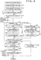
- Fig. 8 is a flowchart explanatory of the first PLP search process.
- the control circuit 31 goes to step S11 and acquires a designated PLPID signal corresponding to the designated service information.
- step S12 the control circuit 31 performs an initialization process.
- a counter (i) is initialized and a value (n) is set for the registers 33.
- the value n denotes the number of registers 33 1 through 33 n .
- the value m represents a maximum PLP count that the system can take.
- the value m is set to be 85.
- the control section 16 in Fig. 6 has 85 registers 33 installed therein.
- the value i is illustratively set to be 1 and the value n to be 85.
- step S15 If in step S15 the PLP type is found to be "common,” then step S16 is reached. In step S16, the control circuit 31 checks to determine whether a relationship of i ⁇ n is satisfied.
- step S15 involves checking to see if there exist the registers 33 n for storing the PLP information signals of which the PLP type is found to be "common.”
- step S16 a check is made to determine whether the relationship of i ⁇ n is satisfied, i.e., whether there exists the register 33 i corresponding to the i-th Common PLP. If the result of the check in step S16 is affirmative, then step S17 is reached. In step S17, the control circuit 31 updates the register 33 i using the PLP information signal of the acquired Common PLP. In step S18, the control circuit 31 increments the value i by 1. This allows the register 33 i to hold the PLP information signal of the i-th Common PLP.
- step S15 the control circuit 31 determines the PLP type of the next PLP information signal thus acquired. If the PLP type is found to be "common” in the manner described above, the PLP information signal of the i-th Common PLP is written to the register 33 i . Then the next PLP signal information is acquired. If in step S15 the PLP type is found to be "data,” then control is passed on to step S23.
- step S23 the control circuit 31 checks to determine whether a GroupID is identified. If any GroupID has yet to be identified, then step S24 is reached. In step S24, the control circuit 31 checks to determine whether the PLPID included in the PLP information signal of the acquired Data PLP coincides with the designated PLPID.
- step S24 If in step S24 the PLPID's are not found to match, control is passed on to step S21.
- step S21 a check is made to determine whether the next PLP information signal exists. If the next PLP information signal is found to exist, then control is returned to step S22 and the subsequent steps are repeated as explained above.
- step S25 the control circuit 31 updates the register 32 using the PLP information signal of the acquired Data PLP. This allows the register 32 to hold the PLP information signal of the Data PLP corresponding to the designated PLPID.
- step S20 the control circuit 31 checks to determine whether any of the GroupID j (1 ⁇ j ⁇ i) included in the PLP information signals of the Common PLP's held in the registers 33 1 through 33 i coincides with the GroupID (called the specific GroupID) included in the PLP information signal of the Data PLP placed in the register 32.
- step S20 If in step S20 the GroupID j coinciding with the specific GroupID is found to exist, then step S26 is reached.
- the control circuit 31 supplies the selector 34 with a Common PLP selection signal for selecting the output from the register 33 j that retains the PLP information signal including the GroupID j coinciding with the specific GroupID. This step brings the first PLP search process to an end.
- the selector 34 selects the output from the register 33 j that holds the PLP information signal including the GroupID j coinciding with the specific GroupID, and sends what is selected to the decoding process section 13.
- the register 32 supplies the PLP information signal of the Data PLP to the decoding process section 13.
- the decoding process section 13 performs a PLP decoding process using the designated Data PLP and the Common PLP appended to that Data PLP.
- step S21 a check is made to determine whether the next PLP information exists. If the next PLP information is found to exist, then step S22 is reached again and the subsequent steps are repeated as explained above.
- the PLP information signal in question is held in the register 33 i , and a check is made to determine whether the GroupID j coincides with the specific GroupID. If these GroupID's are found to match, then the register 33 i is selected and its PLP information signal is fed to the decoding process section 13. If the PLP type is found to be "data,” that means the GroupID has already been identified ("No" in step S23). In this case, the register 32 is not updated, and only the PLP information about the PLP type being "common” is processed.
- the control circuit 31 may compare the GroupID included in the PLP information of the acquired Common PLP directly with the specific GroupID. Only in the case of a match between the GroupID's, the control circuit 31 can place the PLP information in question into the register 33 i .
- step S27A a check is made to determine whether the GroupID is identified. If in step S27A the GroupID is found identified, that means there exists no Common PLP that would have the specific GroupID from beginning to end of one T2 frame.
- step S28 is reached and the control circuit 31 sends a no-common signal to the decoding process section 13.
- This step terminates the first PLP search process. This causes the decoding process section 13 to perform a PLP decoding process only on the designated Data PLP. If in step S27A no GroupID is found identified, that means there is no Data PLP corresponding to the designated PLPID signal. The control circuit 31 then goes to step S27B and supplies a no-data signal to the decoding process section 13. This step brings the process to an end.
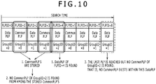
- the PLP information about the Common PLP is acquired and stored until the GroupID is identified. This makes it possible to terminate the PLP search process always within one T2 frame.
- the decoding process section 13 can then perform a fast decoding process using the PLP information acquired quickly through such PLP search.
- the designated PLPID is assumed to be 4 in both Fig. 9 and Fig. 10 .
- a search is started from the beginning.
- the time required for PLP acquisition is complete within a single T2 frame. Because there is no need to perform a PLP search for the next T2 frame, the search time can be shortened so that the PLP decoding process can be made faster than before.
- the number (n) of registers 33 is brought to within a range of 1 ⁇ n ⁇ m.
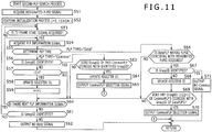
- Fig. 11 is a flowchart explanatory of the second PLP search process.
- the control circuit 31 acquires a designated PLPID signal.
- the control circuit 31 carries out an initialization process.
- the initial value i on the counter for registers 33 is set to 1, and the value n representing the number of registers 33 is established (1 ⁇ n ⁇ m). Since the value m is set to 85 under DVB-T2 as mentioned above, the value n is determined in a manner meeting the range of 1 ⁇ n ⁇ 85.
- steps S53 through S55 as in steps S13 through S15 of Fig. 8 , a T2 frame start signal is acquired; a PLP information signal is acquired; and the PLP type is determined. If in step S55 the PLP type is found to be "common,” then control S56 is reached. In step S56, the control circuit 31 checks to determine whether a GroupID is identified.
- step S57 the control circuit 31 checks to determine whether a relationship of i ⁇ n is satisfied. If in step S57 the relationship of i ⁇ n is found satisfied, i.e., if the register 33 i corresponding to the i-th Common PLP is found to exist, then step S58 is reached. In step S58, the control circuit 31 updates the register 33 i using the PLP information signal of the acquired Common PLP. In step S59, the control circuit 31 increments the value i by 1. This allows the register 33 i to hold the PLP information of the i-th Common PLP. If in step S57 the relationship of i ⁇ n is not found satisfied, then steps S58 and S59 are skipped and step S60 is reached. In this case, the register 33 i will not be updated.
- step S60 the control circuit 31 checks to determine whether the next PLP information signal exists. If the next PLP information signal is found to exist, step S54 is reached again and the next PLP information signal is acquired. In step S55, the control circuit 31 again determines the PLP type of the next PLP information signal acquired. If the PLP type is found to be "data,” then step S66 is reached. In step S66, the control circuit 31 checks to determine whether the PLPID included in the PLP information signal of the acquired Data PLP coincides with the designated PLPID.
- step S66 If in step S66 the Data PLP having a PLPID coinciding with the designated PLPID is found acquired, then step S67 is reached.
- step S67 the control circuit 31 checks to determine whether the GroupID is identified. If in step S67 no GroupID is found identified, then step S68 is reached.
- step S68 the control circuit 31 updates the register 32 using the PLP information signal of the acquired Data PLP. This allows the register 32 to hold the PLP information signal of the Data PLP corresponding to the designated PLPID, whereby the GroupID is identified.
- step S69 the control circuit 31 checks to determine whether any of the GroupID j (1 ⁇ j ⁇ i) included in the PLP information signals of the Common PLP's held in the registers 33 1 through 33 i coincides with the GroupID (specific GroupID) included in the PLP information signal of the Data PLP placed in the register 32.
- step S70 the control circuit 31 supplies the selector 34 with a Common PLP selection signal for selecting the output from the register 33 j that retains the PLP information signal including the GroupID j coinciding with the specific GroupID. This step brings the second PLP search process to an end.
- step S60 a check is made to determine whether the next PLP information signal exists ("Yes” in step S60). If the result of the check in step S60 is affirmative, then step S54 is reached again and the subsequent steps are repeated as described above regarding the next PLP information signal acquired anew.
- step S63 the control circuit 31 checks to determine whether the GroupID included in the PLP information signal of the Common PLP coincides with the specific GroupID. If in step S63 the GroupID's are found to match, then step S64 is reached. In step S64, the control circuit 31 updates the register 33 i using the PLP information signal of the acquired Common PLP. In step S65, the control circuit 31 sends the corresponding Common PLP selection signal to the selector 34. This brings the second PLP search process to an end. If in step S63 the GroupID's are not found to match, then step S60 is reached again and the subsequent steps are repeated.
- step S60 While the steps are being repeated, it may be found in step S60 that the next PLP information signal does not exist. If that is the case, step S61 is reached. In step S61, a check is made to determine whether the GroupID is identified. If no GroupID is found identified in step S61, then the control circuit 31 sends a no-data signal to the decoding process section 13 and brings the search process to an end. In this case, the next PLP information signal is not found to exist ("No" in step S60), so that the GroupID has yet to be identified although the PLP search is completed within one T2 frame. This means that the Data PLP corresponding to the designated PLPID does not exist. Hence comes the output of the no-data signal.
- step S53 is reached again and the subsequent steps are repeated. Following acquisition of a second T2 frame start signal ("Yes" in step S53), the same PLP search process is performed on the second T2 frame as on the first T2 frame.
- a search is made through the second T2 frame for a Common PLP having a GroupID coinciding with the specific GroupID.
- the desired Common PLP is identified, the corresponding Common PLP selection signal is sent to the selector 34.
- the PLP search through the first T2 frame resulted in the acquisition of the Data PLP having the PLPID coinciding with the designated PLPID, another Data PLP having the same PLPID is acquired in the second T2 frame. If that happens, that means the PLP search process has completed a full circle ("Yes" in step S67). In this case, there is no use performing continuously the PLP search process searching for the desired Common PLP.
- the control circuit 31 goes to step S71, outputs a no-common signal to the decoding process section 13, and terminates the search process.
- the second PLP search process entails the reduced number of registers for storing the PLP information of Common PLP's. If the desired PLP information is identified from within the first T2 frame, then the PLP search process is finished rapidly within one T2 frame. This allows the decoding process section 13 to perform its decoding process at high speed.
- n is smaller than the value m, that means the number of registers 33 is smaller than the number of Common PLP's.
- the PLP search process may not be completed within the first T2 frame. But the search can be continued past the first T2 frame and into the second T2 frame for the desired PLP.
- a search is started from the beginning.
- n is determined in consideration of a tradeoff between the need for accelerating the decoding process of the decoding process section 13 on the one hand the affordable number of registers 33 on the other hand. If the priority is on acceleration of the decoding process of the decoding process section 13, then the number of registers 33 may be arranged to be increased (i.e., value n made larger). This arrangement boosts the possibility of identifying the PLP within the first T2 frame, so that the decoding process can be accelerated in most cases.
- Fig. 13 is a block diagram showing another typical structure of the control section 16.
- the components also found in Fig. 6 are designated by like reference numerals, and their descriptions will be omitted hereunder where redundant.
- the control section 16 in Fig. 13 differs from its counterpart in Fig. 6 in that a selection circuit 41 replaces the selector 34.
- the selection circuit 41 is supplied with a Common PLP selection signal from the control circuit 31.
- the selection circuit 41 selects PLP information input from any one of the registers 33 1 through 33 n and outputs what is selected to the decoding process section 13.
- the number of Common PLP's may turn out to be smaller than a predetermined Common PLP count x.
- the control circuit 31 sends to the decoding process section 13 a common-lacking signal indicating that the number of Common PLP's falls short of the predetermined count.
- step S91 the control circuit 31 acquires the designated PLPID signal.
- step S92 the control circuit 31 performs an initialization process.
- Steps S93 through S105 are carried out in the same manner as steps S13 through S25 in Fig. 8 .
- the control circuit 31 searches for a Common PLP appended to the designated Data PLP.
- step S100 the control circuit 31 checks to determine whether any of the GroupID j (1 ⁇ j ⁇ i) included in the PLP information signals of the Common PLP's held in the registers 33 1 through 33 j coincides with the specific GroupID.
- step S106A the control circuit 31 increments the value y by 1.
- step S106B the control circuit 31 supplies the selection circuit 41 with a Common PLP selection signal for selecting the output from the register 33 j .
- the signal causes the selection circuit 41 to send the output from the register 33 j to the decoding process section 13 as a PLP information signal y (1 ⁇ y ⁇ x).
- the Common PLP selection signal is an instruction that causes the selection circuit 41 to select, from among the PLP information signals 1 through i retained in the registers 33 1 through 33 j , the PLP information signals 1 through x corresponding to the known value x and to output the selected signals.
- the control circuit 31 outputs a Common PLP selection signal for outputting the input from the register 33 j as a PLP information signal 1.
- the control circuit 31 outputs a Common PLP selection signal for selectively outputting a PLP information signal y from the corresponding register 33 j .
- the selection circuit 41 is supplied with a Common PLP selection signal for causing the output from the register 33 j holding the matching GroupID to be output as the PLP information signal y.
- the value y is incremented by 1.
- the value y approaches the value x.
- the PLP information of all Common PLP's relative to the desired Data PLP is fed to the decoding process section 13.
- the decoding process section 13 performs its PLP decoding process using the designated Data PLP and the predetermined number of Common PLP's appended to that Data PLP.
- step S107A as in step S27A of Fig. 8 , the control circuit 31 checks to determine whether the GroupID is identified. If in step S107A no GroupID is found identified yet, step S107B is reached. In step S107B, the control circuit 31 sends a no-data signal to the decoding process section 13 and brings the search process to an end. If in step S107A the GroupID is found identified, then step S108A is reached. In step S108A, the control circuit 31 checks to determine whether the relationship of y ⁇ x is satisfied, i.e., whether all Common PLP relative to the desired Data PLP have been acquired.
- step S108A If in step S108A not all Common PLP's are found acquired yet, step S108B is reached.
- the control circuit 31 sends a common-lacking signal to the decoding process section 13 and terminates the search process. If in step S108A all Common PLP's are found to have been acquired, then there is no need to output the common-lacking signal. In that case, step S108B is skipped and the search process is brought to an end.
- the decoding process section 13 can perform its decoding process at high speed using the PLP information acquired rapidly through the above-described PLP search process.
- the number n of registers 33 coincides with the maximum Common PLP count (m). While it is possible for the PLP information of all Common PLP's to be held in the registers 33 n , this entails preparing the numerous registers 33.
- the number n of registers 33 is set in such a manner that a relationship of 1 ⁇ x ⁇ n ⁇ m is satisfied. Although it is impossible to accommodate the PLP information of all Common PLP's, the number of registers 33 can be reduced appreciably.
- Fig. 15 is a flowchart explanatory of the fourth PLP search process.
- step S131 the control circuit 31 acquires the designated PLPID signal.
- step S132 the control circuit 31 performs an initialization process.
- steps S133 through S151 in Fig. 15 correspond respectively to steps S51 through S71 in Fig. 11 although some steps are different because there exist a plurality of Common PLP's. More specifically, the differences are that steps S145A through S145C in Fig. 15 correspond to step S65 in Fig. 11 , that steps S149A through S149C correspond to step S69 in Fig. 11 , and that steps S150A through S150C in Fig. 15 correspond to step S70 in Fig. 11 . The ensuing description will be focused on these differences.
- step S146 the Data PLP having the PLPID coinciding with the designated PLPID is found acquired ("Yes" in step S146), then the PLP information signal of the Data PLP corresponding to the designated PLPID is written to the register 32, and the GroupID is identified (step S148).
- step S149A the control circuit 31 checks to determine whether any of the GroupID j (1 ⁇ j ⁇ i) included in the PLP information signals of the Common PLP's coincides with the GroupID (specific GroupID) included in the PLP information signal of the Data PLP.
- step S150A the control circuit 31 supplies the selection circuit 41 with a Common PLP selection signal for selecting the output from the register 33 j that holds the PLP information signal containing the GroupID j coinciding with the specific GroupID.
- step S150B the control circuit 31 increments the value y by 1.
- the number of registers for holding the PLP information of the Common PLP's is reduced appreciably. If the desired PLP information is identified within the first T2 frame, the PLP search process is finished rapidly within one T2 frame. This allows the decoding process section 13 to perform its decoding process at high speed.
- the designated PLPID is assumed to be 6.
- There are provided four registers 33 1 through 33 4 in order to reduce the number of registers (n 4).
- the PLP search through the first T2 frame is to be terminated.
- the process is put on hold until a second T2 frame start signal is given.
- the PLP search process is resumed.
- the PLP information in the register 33 1 is selected by the selection circuit 41 and later output as a PLP information signal 3.
- the value n is determined in consideration of a tradeoff between the need for accelerating the decoding process of the decoding process section 13 on the one hand the affordable number of registers 33 on the other hand. Because as many as x pieces of Common PLP decoding information are to be written to the n registers 33, the relationship of n ⁇ x must always be satisfied.
- Fig. 17 is a block diagram showing another typical structure of the control section 16.
- the components also found in Fig. 13 are designated by like reference numerals, and their descriptions will be omitted hereunder where redundant.
- the control circuit 31 does not send the common-lacking signal the decoding process section 13. This is because the number x of Common PLP's is indefinite so that it is unclear whether the number of detected Common PLP's is sufficient or not.
- step S171 the control circuit 31 acquires the designated PLPID signal.
- step S172 the control circuit 31 performs an initialization process.
- step S173 through S185 the control circuit 31 searches for the Common PLP's appended to the designated Data PLP.
- step S180 the control circuit 31 checks to determine whether any of the GroupID j (1 ⁇ j ⁇ i) included in the PLP information signals of the Common PLP's held in the registers 33 1 through 33 j coincides with the specific GroupID.
- step S186A the control circuit 31 increments the value y by 1.
- step S186B the control circuit 31 supplies the selection circuit 41 with a Common PLP selection signal for selecting the output from the register 33 j .
- the signal causes the selection circuit 41 to supply the decoding process section 13 with the output from the register 33 j as a PLP information signal y (1 ⁇ y ⁇ x).
- Control is then passed on to step S181 and the subsequent steps described above are repeated. That is, a check is made to determine whether the GroupID included in the PLP information of which the PLP type is "common" coincides with the specific GroupID. If these GroupID's are found to match, then the selection circuit 41 is fed with a Common PLP selection signal for causing the output of the register 33 j holding the matching GroupID to be output as a PLP information signal y. These steps are repeated until the next PLP information signal is exhausted ("No" in step S181).
- the PLP search process is always finished within one T2 frame. This allows the decoding process section 13 to perform its decoding process at high speed using the PLP information acquired rapidly through the search process.
- Fig. 19 is a schematic view showing a configuration example of the first embodiment of the reception system according to the present invention.
- the reception system is made up of an acquisition section 201, a transmission channel decoding process section 202, and an information source decoding process section 203.
- the acquisition section 201 acquires the OFDM signal according to the M-PLP method under DVB-T2 via a transmission channel not shown such as a terrestrial digital broadcast, a satellite digital broadcast, a CATV (cable television) network, the Internet, or some other network.
- the OFDM signal thus acquired is sent to the transmission channel decoding process section 202.
- the acquisition section 201 is composed of a tuner or a set-top box (STB) as in the case of the acquisition section 12 in Fig. 5 . If the OFDM signal is sent illustratively from web servers in multicast fashion as in the case of IPTV (Internet Protocol Television), then the acquisition section 201 is formed by a network interface such as NIC (network interface card).
- NIC network interface card
- a single acquisition section 201 receives a plurality of OFDM signals coming from a plurality of transmission apparatuses over a plurality of transmission channels. These OFDM signals are synthesized resultantly into a single OFDM signal when received by the acquisition section 201.
- the transmission channel decoding process section 202 performs a transmission channel decoding process including at least PLP decoding on the OFDM signal acquired by the acquisition section 201 over the transmission channel.
- the signal resulting from the process is forwarded to the information source decoding process section 203.
- the OFDM signal according to the M-PLP method is formed by a plurality of Data PLP's composed of the packets left behind after extracting from a plurality of transport streams (TS's) those packets common to all TS's, and by Common PLP's constituted by the packets common to the TS's.
- the transmission channel decoding process section 202 typically performs a PLP (packet sequence) decoding process on that OFDM signal.
- the OFDM signal acquired by the acquisition section 201 over the transmission channel is an OFDM signal in a distorted state caused by transmission channel characteristics.
- the transmission channel decoding section 202 illustratively carries out demodulation processes such as transmission channel estimation, channel estimation, and phase estimation.
- the transmission channel decoding process may include the process of correcting errors that may have occurred over the transmission channel.
- error correction coding may be LDPC coding or Reed-Solomon coding.
- the information source decoding process section 203 performs an information source decoding process including at least the process of decompressing the signal having undergone the transmission channel decoding process.
- the decoding process expands the compressed information back to the original information.
- the OFDM signal acquired by the acquisition section 201 over the transmission channel may have been compression-coded in order to reduce the amount of data such as images and sounds.
- the information source decoding process section 203 carries out its information source decoding process including the process of decompressing the compressed signal (i.e., decompression process) having undergone the transmission channel decoding process, whereby the compressed information is expanded back to the original information.
- the information source decoding process section 203 will not perform the process of decompressing the compressed information.
- a typical decompression process is MPEG decoding.
- the transmission channel decoding process may include descrambling in addition to the decompression process.
- the acquisition section 201 acquires over the transmission channel the OFDM signal which is made up of image and sound data having undergone compression coding such as MPEG coding and which further underwent error correction coding according to the M-PLP method.
- the OFDM signal thus acquired is forwarded to the transmission channel decoding process section 202.
- the OFDM signal is acquired in a distorted state caused by transmission channel characteristics.
- the transmission channel decoding process section 202 performs its transmission channel decoding process made up of the same processes as those executed by the decoding process section 13 and control section 16 in Fig. 5 on the OFDM signal coming from the acquisition section 201.
- the signal resulting from the transmission channel decoding process is fed to the information source decoding process section 203.
- the information source decoding process section 203 performs its information source decoding process composed of the same process as that carried out by the decoder 14 in Fig. 5 on the signal coming from the transmission channel decoding process section 202.
- the information source decoding process section 203 outputs the resultant images or sounds.
- the reception system of Fig. 19 structured as described above may be applied illustratively to the TV tuner or the like for receiving digital TV broadcasts.
- the acquisition section 201, transmission channel decoding process section 202, and information source decoding process section 203 may each be structured as a single independent device (e.g., a piece of hardware such as IC (integrated circuit) or a software module).
- the acquisition section 201 may be combined with the transmission channel decoding process section 202 to form a single set of independent equipment.
- a set of independent equipment may also be formed by the combination of the transmission channel decoding section 202 and information source decoding process section 203, or by the combination of the acquisition section 202, transmission channel decoding section 202, and information source decoding process section 203.
- Fig. 20 is a schematic view showing a configuration example of the second embodiment of the reception system according to the present invention.
- the components also found in Fig. 19 are designated by like reference numerals, and their descriptions will be omitted hereunder where redundant.
- the reception system in Fig. 20 is similar to its counterpart in Fig. 19 in that the system includes the acquisition section 201, transmission channel decoding process section 202, and information source decoding process section 203.
- the reception system in Fig. 20 differs from its counterpart in Fig. 19 in that an output section 211 is provided anew.
- the output section 211 is illustratively a display device for displaying images and/or speakers for outputting sounds. As such, the output section 211 outputs the video and audio data constituted by the signal output from the information source decoding process section 203. Specifically, the output section 211 outputs images or sounds.
- the reception system of Fig. 20 structured as outlined above may be applied illustratively to the TV set for receiving digital TV broadcasts, the radio receiver for receiving radio broadcasts, and the like. If the OFDM signal acquired by the acquisition section 201 is not found compression-coded, then the signal output from the transmission channel decoding process section 202 is sent directly to the output section 211.
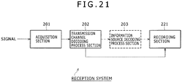
- Fig. 21 is a schematic view showing a configuration example of the third embodiment of the reception system according to the present invention.
- the components also found in Fig. 19 are designated by like reference numerals, and their descriptions will be omitted hereunder where redundant.
- the reception system in Fig. 21 is similar to its counterpart in Fig. 19 in that the system includes the acquisition section 201 and transmission channel decoding process section 202.
- the reception system in Fig. 21 is different from its counterpart in Fig. 19 in that the information source decoding process section 203 is omitted and that a recording section 221 is provided anew.
- the recording section 221 writes (i.e., records) the signal (e.g., TS packets making up MPEG transport streams) output from the transmission channel decoding process section 202 to recording (storage) media such as optical disks, hard disks (magnetic disks), or flash memories.
- the signal e.g., TS packets making up MPEG transport streams
- recording (storage) media such as optical disks, hard disks (magnetic disks), or flash memories.
- the reception system of Fig. 21 structured as described above may be applied illustratively to the recorder or the like for recording TV broadcasts.
- the reception system may be structured to include the information source decoding process section 203.
- the recording section 221 can record decoded images and sounds derived from the signal having undergone the information source decoding process carried out by the information source decoding process section 203.
- the series of the processes described above may be executed either by hardware or by software.
- the programs constituting the software are installed into suitable computers for process execution.
- Such computers include one with the software installed beforehand in its dedicated hardware, and a general-purpose personal computer or like equipment capable of executing diverse functions based on the programs installed therein.
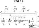
- Fig. 22 is a schematic view showing a composition example of the hardware of a computer that carries out the series of the above-described processes.
- a CPU central processing unit
- ROM read only memory
- RAM random access memory
- An input/output interface 405 is further connected to the bus 404.
- the input/output interface 405 is connected with an input device 406, an output device 407, a storage device 408, a communication device 409, and a drive 410.
- the input device 406 is illustratively made up of a keyboard, a mouse, and a microphone.
- the output device 407 is typically composed of a display device and a speaker.
- the storage device is typically composed of a hard disk, a nonvolatile memory, or the like.
- the communication device 409 is generally constituted by a network interface.
- the drive 410 drives removable media 411 such as a magnetic disk, an optical disk, a magneto-optical disk, or a semiconductor memory.
- the CPU 401 performs the series of the above-described processes by loading relevant programs from the storage device 408 into the RAM 403 through the input/output interface 405 and bus 404 and by executing the loaded programs.
- the programs to be executed by the computer may be recorded on the removable media 411 such as package media when offered to users.
- the programs may also be offered via wired or wireless transmission media such as local area networks, the Internet, or digital broadcasts.
- the programs may be installed into the storage device 408 from the removable media 411 by way of the input/output interface 405, the removable media 411 being attached to the drive 410.
- the programs may also be installed into the storage device 408 after being received by the communication device 409 via wired or wireless media.
- the programs may be preinstalled in the ROM 402 or storage device 408.
- the steps describing the programs stored on the recording medium represent not only the processes that are to be carried out in the depicted sequence (i.e., on a time series basis) but also processes that may be performed parallelly or individually and not necessarily chronologically.
- system refers to a logical configuration of a plurality of component devices.
Claims (15)
- Appareil de réception comprenant :un moyen de réception (11)
pour recevoir un signal de multiplexage par répartition en fréquences orthogonales connu sous le nom de signal OFMD formé par la modulation de séquences de paquets communs et de séquences de paquets de données, lesdites séquences de paquets communs étant constituées de paquets communs à une pluralité de flux, lesdites séquences de paquets de données étant constituées de paquets uniques à chacun de ladite pluralité de flux ;un moyen d'acquisition (12, 13)
pour acquérir des informations de décodage pour décoder les flux d'origine à partir desdites séquences de paquets communs et desdites séquences de paquets de données obtenues par la démodulation du signal OFDM reçu ; etun moyen de recherche (16, 31)
pour rechercher la séquence de paquets communs nécessaire pour décoder les flux d'origine à partir de la séquence de paquets de données désignée sur la base des informations de décodage acquises,caractérisé par un moyen de stockage (331 - 33n) stockant les informations de décodage sur la séquence de paquets communs acquise jusqu'à ce que les informations de décodage sur ladite séquence de paquets de données désignée soient acquises ;et caractérisé en outre en ce que le moyen de recherche est configuré de sorte que, lorsque les informations de décodage sur ladite séquence de paquets de données sont acquises, ledit moyen de recherche recherche dans les informations de décodage sur ladite séquence de paquets communs stockées les informations de décodage identifiées par les informations de décodage sur les séquences de paquets de données acquises. - Appareil de réception selon la revendication 1, configuré de sorte que, si les informations de décodage ne peuvent pas être identifiées à partir des informations de décodage sur lesdites séquences de paquets communs stockées, ledit moyen de recherche recherche les informations de décodage identifiées par les informations de décodage sur les séquences de paquets de données acquises à l'aide d'informations de décodage sur lesdites séquences de paquets communs acquises suite à l'acquisition des informations de décodage sur ladite séquence de paquets de données désignée.
- Appareil de réception selon la revendication 1 ou 2, dans lequel ledit moyen de stockage est constitué de jusqu'à n registres, le nombre n satisfaisant une relation n=m où m désigne un nombre maximal d'unités des informations de décodage sur lesdites séquences de paquets communs ; l'appareil étant configuré de sorte que si les informations de décodage sur lesdites séquences de paquets communs ne peuvent pas être identifiées à partir d'une première trame ciblée pour la recherche, ledit moyen de recherche détermine que lesdites séquences de paquets communs n'existent pas.
- Appareil de réception selon la revendication 3, dans lequel ledit moyen de recherche est configuré pour rechercher un nombre prédéterminé d'unités des informations de décodage sur lesdites séquences de paquets communs qui sont identifiées par les informations de décodage sur ladite séquence de paquets de données désignée.
- Appareil de réception selon la revendication 1 ou 2, dans lequel ledit moyen de stockage est constitué de jusqu'à n registres, le nombre n satisfaisant une relation 1≤n≤m où m désigne un nombre maximal d'unités des informations de décodage sur lesdites séquences de paquets communs ; l'appareil étant configuré de sorte que si les informations de décodage sur lesdites séquences de paquets communs ne peuvent pas être identifiées à partir d'une première trame ciblée pour la recherche, ledit moyen de recherche recherche dans une deuxième trame à côté de ladite première trame.
- Appareil de réception selon la revendication 5, dans lequel ledit moyen de recherche est configuré pour rechercher un nombre prédéterminé, x, d'unités des informations de décodage sur lesdites séquences de paquets communs qui sont identifiées par les informations de décodage sur ladite séquence de paquets de données désignée, le nombre x satisfaisant une relation 1≤x≤n≤m.
- Appareil de réception selon l'une des revendications 1 à 6, dans lequel ledit moyen de recherche est configuré pour rechercher un nombre indéfini d'unités des informations de décodage sur lesdites séquences de paquets communs identifiées par les informations de décodage sur ladite séquence de paquets de données désignée.
- Appareil de réception selon l'une des revendications 1 à 7, dans lequel lesdites informations de décodage incluent au moins un premier et un deuxième identifiant, ledit premier identifiant identifiant chaque séquence de paquets, ledit deuxième identifiant distinguant la séquence de paquets communs correspondante desdites séquences de paquets de données ; et
ledit moyen de recherche est configuré pour identifier les informations de décodage sur la séquence de paquets de données ayant le premier identifiant désigné, avant l'identification des informations de décodage sur la séquence de paquets communs ayant ledit deuxième identifiant inclus dans les informations de décodage sur ladite séquence de paquets de données. - Appareil de réception selon l'une des revendications 1 à 8, comprenant en outre
un moyen de décodage pour décoder les flux d'origine à partir desdites séquences de paquets communs et desdites séquences de paquets de données en fonction d'un résultat de la recherche effectuée par ledit moyen de recherche. - Appareil de réception selon l'une des revendications 1 à 9, dans lequel lesdites séquences de paquets communs et lesdites séquences de paquets de données sont constituées, respectivement, par des Common PLP (pour common physical pipe layers) et par des Data PLP (pour data physical pipe layers) générés à partir d'une pluralité de flux d'origine selon une méthode M-PLP (pour multiple physical layer pipe sous DVB-T2).
- Procédé de réception pour indiquer à un appareil de réception comprenant un moyen de réception (11), un moyen d'acquisition (12, 13), un moyen de recherche (16, 31) et un moyen de stockage (331 - 33n) d'exécuter une procédure comprenant les étapes consistant à :recevoir, par le moyen de réception (11), un signal de multiplexage par répartition en fréquences orthogonales connu sous le nom de signal OFMD formé par la modulation de séquences de paquets communs et de séquences de paquets de données, lesdites séquences de paquets communs étant constituées de paquets communs à une pluralité de flux, lesdites séquences de paquets de données étant constituées de paquets uniques à chacun de ladite pluralité de flux ;acquérir, par le moyen d'acquisition (12, 13), des informations de décodage (S1) pour décoder les flux d'origine à partir desdites
séquences de paquets communs et desdites séquences de paquets de données obtenues par la démodulation du signal OFMD reçu ; etrechercher (S2), par le moyen de recherche (16, 31), la séquence de paquets communs nécessaire pour décoder les flux d'origine à partir de la séquence de paquets de données désignée sur la base des informations de décodage acquises,caractérisé par une étape de stockage (S14 - S19, S21, S22), par le moyen de stockage (331 - 33n), des informations de décodage sur la séquence de paquets communs acquise jusqu'à ce que les informations de décodage sur ladite séquence de paquets de données désignée soient acquises ;et caractérise en outre en ce que,
lorsque les informations de décodage sur ladite séquence de paquets de données désignée sont acquises, (S24), l'étape de recherche (S2), par le moyen de recherche (16, 31), de la séquence de paquets communs nécessaire pour décoder les flux d'origine à partir de la séquence de paquets de données désignée sur la base des informations de décodage acquises comprend :
la recherche (S20) dans les informations de décodage sur lesdites séquences de paquets communs stockées des informations de décodage identifiées par les informations de décodage sur les séquences de paquets de données acquises. - Procédé de réception selon la revendication 11, dans lequel, si les informations de décodage ne peuvent pas être identifiées à partir des informations de décodage sur lesdites séquences de paquets communs stockées, rechercher, par ledit moyen de recherche (16, 31), les informations de décodage identifiées par les informations de décodage sur les séquences de paquets de données acquises à l'aide d'informations de décodage sur lesdites séquences de paquets communs, qui sont acquises suite à l'acquisition des informations de décodage sur ladite séquence de paquets de données désignée.
- Procédé de réception selon la revendication 11 ou 12, dans lequel ledit moyen de stockage (331 - 33n) est constitué de jusqu'à n registres, le nombre n satisfaisant une relation n=m où m désigne un nombre maximal d'unités des informations de décodage sur lesdites séquences de paquets communs;
dans lequel, si les informations de décodage sur lesdites séquences de paquets communs ne peuvent pas être identifiées à partir d'une première trame ciblée pour la recherche, déterminer, par ledit moyen de recherche (16, 31), que lesdites séquences de paquets communs n'existent pas. - Procédé de réception selon la revendication 13, comprenant en outre l'étape de recherche, par le moyen de recherche (16, 31), d'un nombre prédéterminé d'unités des informations de décodage sur lesdites séquences de paquets communs qui sont identifiées par les informations de décodage sur ladite séquence de paquets de données désignée.
- Programme indiquant à un ordinateur de mettre en oeuvre les fonctions :de recevoir un signal de multiplexage par répartition en fréquences orthogonales connu sous le nom de signal OFMD formé par la modulation de séquences de paquets communs et de séquences de paquets de données, lesdites séquences de paquets communs étant constituées de paquets communs à une pluralité de flux, lesdites séquences de paquets de données étant constituées de paquets uniques à chacun de ladite pluralité de flux ;d'acquérir des informations de décodage pour décoder les flux d'origine à partir desdites séquences de paquets communs et desdites séquences de paquets de données obtenues par la démodulation du signal OFDM reçu ; etde rechercher la séquence de paquets communs nécessaire pour décoder les flux d'origine à partir de la séquence de paquets de données désignée sur la base des informations de décodage acquises,
caractérisé parle stockage des informations de décodage sur la séquence de paquets communs acquise jusqu'à ce que les informations de décodage sur ladite séquence de paquets de données désignée soient acquises ; et,lorsque les informations de décodage sur ladite séquence de paquets de données sont acquises, la recherche dans les informations de décodage sur ladite séquence de paquets communs stockées des informations de décodage identifiées par les informations de décodage sur les séquences de paquets de données acquises.
Applications Claiming Priority (1)
| Application Number | Priority Date | Filing Date | Title |
|---|---|---|---|
| JP2009294546A JP5476981B2 (ja) | 2009-12-25 | 2009-12-25 | 受信装置及び方法、プログラム、並びに受信システム |
Publications (3)
| Publication Number | Publication Date |
|---|---|
| EP2339805A2 EP2339805A2 (fr) | 2011-06-29 |
| EP2339805A3 EP2339805A3 (fr) | 2016-12-21 |
| EP2339805B1 true EP2339805B1 (fr) | 2019-07-17 |
Family
ID=43806981
Family Applications (1)
| Application Number | Title | Priority Date | Filing Date |
|---|---|---|---|
| EP10194977.4A Active EP2339805B1 (fr) | 2009-12-25 | 2010-12-14 | Appareil de réception, procédé de réception, programme et système de réception |
Country Status (4)
| Country | Link |
|---|---|
| US (1) | US8553809B2 (fr) |
| EP (1) | EP2339805B1 (fr) |
| JP (1) | JP5476981B2 (fr) |
| CN (1) | CN102111370B (fr) |
Families Citing this family (11)
| Publication number | Priority date | Publication date | Assignee | Title |
|---|---|---|---|---|
| CA2789648C (fr) | 2010-02-11 | 2018-08-21 | Sony Corporation | Appareil et procede de mappage pour transmission de donnees dans un systeme de diffusion multi-porteuses |
| JP5908833B2 (ja) * | 2010-12-10 | 2016-04-26 | パナソニック株式会社 | 送信装置、受信装置、送信方法及び受信方法 |
| JP5786409B2 (ja) * | 2011-03-31 | 2015-09-30 | ソニー株式会社 | 受信装置、受信方法、プログラム、および受信システム |
| EP2597805A4 (fr) * | 2011-06-24 | 2013-07-24 | Panasonic Corp | Dispositif de transmission, procédé de transmission, dispositif de réception et procédé de réception |
| GB201208389D0 (en) | 2012-05-10 | 2012-06-27 | Samsung Electronics Co Ltd | Integrated circuit, communication unit, wireless communication system and methods therefor |
| CN104113716A (zh) * | 2013-04-16 | 2014-10-22 | 扬智科技股份有限公司 | 数码视频广播接收模块及其运作方法 |
| KR101752434B1 (ko) * | 2014-08-22 | 2017-07-03 | 엘지전자 주식회사 | 방송 전송 장치, 방송 전송 장치의 동작 방법. 방송 수신 장치 및 방송 수신 장치의 동작 방법 |
| EP3267690B1 (fr) * | 2015-03-04 | 2020-05-06 | Sony Corporation | Appareil de réception, procédé de réception, appareil d'émission et procédé d'émission |
| KR20230170776A (ko) | 2015-04-08 | 2023-12-19 | 원 미디어, 엘엘씨 | 진보한 데이터 셀 리소스 매핑 |
| JP2019216325A (ja) | 2018-06-12 | 2019-12-19 | ソニーセミコンダクタソリューションズ株式会社 | 受信装置、および、受信装置の制御方法 |
| WO2023178282A2 (fr) * | 2022-03-18 | 2023-09-21 | Lenovo (Singapore) Pte. Ltd | Signalisation de dispositif de groupe pour compenser des informations périmées dans un réseau non terrestre (ntn) |
Family Cites Families (15)
| Publication number | Priority date | Publication date | Assignee | Title |
|---|---|---|---|---|
| JP2002330433A (ja) * | 2001-04-27 | 2002-11-15 | Matsushita Electric Ind Co Ltd | 無線伝送システム |
| CN100536555C (zh) * | 2003-03-19 | 2009-09-02 | 松下电器产业株式会社 | 数据处理装置 |
| CN1788443B (zh) * | 2003-07-29 | 2012-11-14 | 富士通株式会社 | Ofdm系统中的导频复用方法 |
| US8738056B2 (en) * | 2006-05-22 | 2014-05-27 | Qualcomm Incorporation | Signal acquisition in a wireless communication system |
| DK2238798T3 (en) * | 2008-01-29 | 2018-07-30 | Nokia Technologies Oy | BURST SEPARATION SYSTEM AND PROCEDURE AND EXTENDED INTERLEAVING LENGTH |
| EP2086237B1 (fr) * | 2008-02-04 | 2012-06-27 | Alcatel Lucent | Procédé et dispositif pour enregistrer et multidiffuser des paquets multimédia à partir de flux multimédia appartenant à des sessions apparentées |
| KR100937429B1 (ko) * | 2008-02-04 | 2010-01-18 | 엘지전자 주식회사 | 신호 송수신 방법 및 신호 송수신 장치 |
| JP2009294546A (ja) | 2008-06-06 | 2009-12-17 | Sharp Corp | 画像形成装置 |
| US20100086087A1 (en) * | 2008-10-02 | 2010-04-08 | Nokia Corporation | Transmission Enhancements for Physical Layer Transmission |
| EP2178237A1 (fr) * | 2008-10-20 | 2010-04-21 | Thomson Licensing | Procédé de transmission et réception d'informations de signalisation |
| CN103595686B (zh) * | 2008-10-21 | 2017-05-31 | Lg电子株式会社 | 用于发送和接收信号的装置以及用于发送和接收信号的方法 |
| AU2009311890B2 (en) * | 2008-11-06 | 2013-08-29 | Lg Electronics Inc. | Apparatus for transmitting and receiving a signal and method of transmitting and receiving a signal |
| KR101819525B1 (ko) * | 2009-01-22 | 2018-02-28 | 엘지전자 주식회사 | 신호 송수신 장치 및 방법 |
| WO2010093097A1 (fr) * | 2009-02-12 | 2010-08-19 | Lg Electronics Inc. | Appareil d'émission et de réception d'un signal et procédé d'émission et de réception d'un signal |
| US20110103300A1 (en) * | 2009-10-30 | 2011-05-05 | Nokia Corporation | Data encapsulation and service discovery over a broadcast or multicast system |
-
2009
- 2009-12-25 JP JP2009294546A patent/JP5476981B2/ja not_active Expired - Fee Related
-
2010
- 2010-11-24 US US12/953,862 patent/US8553809B2/en active Active
- 2010-12-14 EP EP10194977.4A patent/EP2339805B1/fr active Active
- 2010-12-17 CN CN201010593783.0A patent/CN102111370B/zh not_active Expired - Fee Related
Non-Patent Citations (1)
| Title |
|---|
| None * |
Also Published As
| Publication number | Publication date |
|---|---|
| EP2339805A3 (fr) | 2016-12-21 |
| CN102111370B (zh) | 2016-05-11 |
| US20110158355A1 (en) | 2011-06-30 |
| EP2339805A2 (fr) | 2011-06-29 |
| CN102111370A (zh) | 2011-06-29 |
| JP5476981B2 (ja) | 2014-04-23 |
| JP2011135457A (ja) | 2011-07-07 |
| US8553809B2 (en) | 2013-10-08 |
Similar Documents
| Publication | Publication Date | Title |
|---|---|---|
| EP2339805B1 (fr) | Appareil de réception, procédé de réception, programme et système de réception | |
| JP5564853B2 (ja) | 受信装置および方法、プログラム、並びに受信システム | |
| US8503583B2 (en) | Receiver, receiving method, program and receiving system | |
| JP5483082B2 (ja) | 受信装置及び方法、プログラム、並びに受信システム | |
| US8446854B2 (en) | Signal processing apparatus, signal processing method, and reception system | |
| TWI425782B (zh) | 接收裝置和接收方法和程式及接收系統 | |
| US8929404B2 (en) | Reception apparatus and method, program and reception system | |
| US8363755B2 (en) | Signal receiving apparatus, method, program and system | |
| US8923420B2 (en) | Reception apparatus, reception method, and program | |
| US20210400316A1 (en) | Transmission device, transmission method, reception device, and reception method | |
| KR20070081759A (ko) | 복조 장치, 복조 방법 및 컴퓨터 프로그램 | |
| US9548765B2 (en) | Transmitting apparatus and receiving apparatus and control method thereof | |
| JP2012095109A (ja) | 受信装置及び方法、復調装置及び方法、並びにプログラム |
Legal Events
| Date | Code | Title | Description |
|---|---|---|---|
| PUAI | Public reference made under article 153(3) epc to a published international application that has entered the european phase |
Free format text: ORIGINAL CODE: 0009012 |
|
| 17P | Request for examination filed |
Effective date: 20101214 |
|
| AK | Designated contracting states |
Kind code of ref document: A2 Designated state(s): AL AT BE BG CH CY CZ DE DK EE ES FI FR GB GR HR HU IE IS IT LI LT LU LV MC MK MT NL NO PL PT RO RS SE SI SK SM TR |
|
| AX | Request for extension of the european patent |
Extension state: BA ME |
|
| PUAL | Search report despatched |
Free format text: ORIGINAL CODE: 0009013 |
|
| AK | Designated contracting states |
Kind code of ref document: A3 Designated state(s): AL AT BE BG CH CY CZ DE DK EE ES FI FR GB GR HR HU IE IS IT LI LT LU LV MC MK MT NL NO PL PT RO RS SE SI SK SM TR |
|
| AX | Request for extension of the european patent |
Extension state: BA ME |
|
| RIC1 | Information provided on ipc code assigned before grant |
Ipc: H04L 27/26 20060101AFI20161115BHEP |
|
| RAP1 | Party data changed (applicant data changed or rights of an application transferred) |
Owner name: SATURN LICENSING LLC |
|
| GRAP | Despatch of communication of intention to grant a patent |
Free format text: ORIGINAL CODE: EPIDOSNIGR1 |
|
| STAA | Information on the status of an ep patent application or granted ep patent |
Free format text: STATUS: GRANT OF PATENT IS INTENDED |
|
| INTG | Intention to grant announced |
Effective date: 20181207 |
|
| GRAJ | Information related to disapproval of communication of intention to grant by the applicant or resumption of examination proceedings by the epo deleted |
Free format text: ORIGINAL CODE: EPIDOSDIGR1 |
|
| STAA | Information on the status of an ep patent application or granted ep patent |
Free format text: STATUS: REQUEST FOR EXAMINATION WAS MADE |
|
| INTC | Intention to grant announced (deleted) | ||
| GRAR | Information related to intention to grant a patent recorded |
Free format text: ORIGINAL CODE: EPIDOSNIGR71 |
|
| GRAS | Grant fee paid |
Free format text: ORIGINAL CODE: EPIDOSNIGR3 |
|
| STAA | Information on the status of an ep patent application or granted ep patent |
Free format text: STATUS: GRANT OF PATENT IS INTENDED |
|
| GRAA | (expected) grant |
Free format text: ORIGINAL CODE: 0009210 |
|
| STAA | Information on the status of an ep patent application or granted ep patent |
Free format text: STATUS: THE PATENT HAS BEEN GRANTED |
|
| AK | Designated contracting states |
Kind code of ref document: B1 Designated state(s): AL AT BE BG CH CY CZ DE DK EE ES FI FR GB GR HR HU IE IS IT LI LT LU LV MC MK MT NL NO PL PT RO RS SE SI SK SM TR |
|
| INTG | Intention to grant announced |
Effective date: 20190611 |
|
| REG | Reference to a national code |
Ref country code: GB Ref legal event code: FG4D |
|
| REG | Reference to a national code |
Ref country code: CH Ref legal event code: EP |
|
| REG | Reference to a national code |
Ref country code: IE Ref legal event code: FG4D |
|
| REG | Reference to a national code |
Ref country code: DE Ref legal event code: R096 Ref document number: 602010060026 Country of ref document: DE |
|
| REG | Reference to a national code |
Ref country code: AT Ref legal event code: REF Ref document number: 1156850 Country of ref document: AT Kind code of ref document: T Effective date: 20190815 |
|
| REG | Reference to a national code |
Ref country code: NL Ref legal event code: MP Effective date: 20190717 |
|
| REG | Reference to a national code |
Ref country code: LT Ref legal event code: MG4D |
|
| REG | Reference to a national code |
Ref country code: AT Ref legal event code: MK05 Ref document number: 1156850 Country of ref document: AT Kind code of ref document: T Effective date: 20190717 |
|
| PG25 | Lapsed in a contracting state [announced via postgrant information from national office to epo] |
Ref country code: FI Free format text: LAPSE BECAUSE OF FAILURE TO SUBMIT A TRANSLATION OF THE DESCRIPTION OR TO PAY THE FEE WITHIN THE PRESCRIBED TIME-LIMIT Effective date: 20190717 Ref country code: SE Free format text: LAPSE BECAUSE OF FAILURE TO SUBMIT A TRANSLATION OF THE DESCRIPTION OR TO PAY THE FEE WITHIN THE PRESCRIBED TIME-LIMIT Effective date: 20190717 Ref country code: AT Free format text: LAPSE BECAUSE OF FAILURE TO SUBMIT A TRANSLATION OF THE DESCRIPTION OR TO PAY THE FEE WITHIN THE PRESCRIBED TIME-LIMIT Effective date: 20190717 Ref country code: BG Free format text: LAPSE BECAUSE OF FAILURE TO SUBMIT A TRANSLATION OF THE DESCRIPTION OR TO PAY THE FEE WITHIN THE PRESCRIBED TIME-LIMIT Effective date: 20191017 Ref country code: NL Free format text: LAPSE BECAUSE OF FAILURE TO SUBMIT A TRANSLATION OF THE DESCRIPTION OR TO PAY THE FEE WITHIN THE PRESCRIBED TIME-LIMIT Effective date: 20190717 Ref country code: HR Free format text: LAPSE BECAUSE OF FAILURE TO SUBMIT A TRANSLATION OF THE DESCRIPTION OR TO PAY THE FEE WITHIN THE PRESCRIBED TIME-LIMIT Effective date: 20190717 Ref country code: NO Free format text: LAPSE BECAUSE OF FAILURE TO SUBMIT A TRANSLATION OF THE DESCRIPTION OR TO PAY THE FEE WITHIN THE PRESCRIBED TIME-LIMIT Effective date: 20191017 Ref country code: LT Free format text: LAPSE BECAUSE OF FAILURE TO SUBMIT A TRANSLATION OF THE DESCRIPTION OR TO PAY THE FEE WITHIN THE PRESCRIBED TIME-LIMIT Effective date: 20190717 Ref country code: PT Free format text: LAPSE BECAUSE OF FAILURE TO SUBMIT A TRANSLATION OF THE DESCRIPTION OR TO PAY THE FEE WITHIN THE PRESCRIBED TIME-LIMIT Effective date: 20191118 |
|
| PG25 | Lapsed in a contracting state [announced via postgrant information from national office to epo] |
Ref country code: LV Free format text: LAPSE BECAUSE OF FAILURE TO SUBMIT A TRANSLATION OF THE DESCRIPTION OR TO PAY THE FEE WITHIN THE PRESCRIBED TIME-LIMIT Effective date: 20190717 Ref country code: GR Free format text: LAPSE BECAUSE OF FAILURE TO SUBMIT A TRANSLATION OF THE DESCRIPTION OR TO PAY THE FEE WITHIN THE PRESCRIBED TIME-LIMIT Effective date: 20191018 Ref country code: RS Free format text: LAPSE BECAUSE OF FAILURE TO SUBMIT A TRANSLATION OF THE DESCRIPTION OR TO PAY THE FEE WITHIN THE PRESCRIBED TIME-LIMIT Effective date: 20190717 Ref country code: ES Free format text: LAPSE BECAUSE OF FAILURE TO SUBMIT A TRANSLATION OF THE DESCRIPTION OR TO PAY THE FEE WITHIN THE PRESCRIBED TIME-LIMIT Effective date: 20190717 Ref country code: AL Free format text: LAPSE BECAUSE OF FAILURE TO SUBMIT A TRANSLATION OF THE DESCRIPTION OR TO PAY THE FEE WITHIN THE PRESCRIBED TIME-LIMIT Effective date: 20190717 Ref country code: IS Free format text: LAPSE BECAUSE OF FAILURE TO SUBMIT A TRANSLATION OF THE DESCRIPTION OR TO PAY THE FEE WITHIN THE PRESCRIBED TIME-LIMIT Effective date: 20191117 |
|
| PG25 | Lapsed in a contracting state [announced via postgrant information from national office to epo] |
Ref country code: TR Free format text: LAPSE BECAUSE OF FAILURE TO SUBMIT A TRANSLATION OF THE DESCRIPTION OR TO PAY THE FEE WITHIN THE PRESCRIBED TIME-LIMIT Effective date: 20190717 |
|
| PG25 | Lapsed in a contracting state [announced via postgrant information from national office to epo] |
Ref country code: RO Free format text: LAPSE BECAUSE OF FAILURE TO SUBMIT A TRANSLATION OF THE DESCRIPTION OR TO PAY THE FEE WITHIN THE PRESCRIBED TIME-LIMIT Effective date: 20190717 Ref country code: PL Free format text: LAPSE BECAUSE OF FAILURE TO SUBMIT A TRANSLATION OF THE DESCRIPTION OR TO PAY THE FEE WITHIN THE PRESCRIBED TIME-LIMIT Effective date: 20190717 Ref country code: EE Free format text: LAPSE BECAUSE OF FAILURE TO SUBMIT A TRANSLATION OF THE DESCRIPTION OR TO PAY THE FEE WITHIN THE PRESCRIBED TIME-LIMIT Effective date: 20190717 Ref country code: IT Free format text: LAPSE BECAUSE OF FAILURE TO SUBMIT A TRANSLATION OF THE DESCRIPTION OR TO PAY THE FEE WITHIN THE PRESCRIBED TIME-LIMIT Effective date: 20190717 Ref country code: DK Free format text: LAPSE BECAUSE OF FAILURE TO SUBMIT A TRANSLATION OF THE DESCRIPTION OR TO PAY THE FEE WITHIN THE PRESCRIBED TIME-LIMIT Effective date: 20190717 |
|
| PG25 | Lapsed in a contracting state [announced via postgrant information from national office to epo] |
Ref country code: SK Free format text: LAPSE BECAUSE OF FAILURE TO SUBMIT A TRANSLATION OF THE DESCRIPTION OR TO PAY THE FEE WITHIN THE PRESCRIBED TIME-LIMIT Effective date: 20190717 Ref country code: CZ Free format text: LAPSE BECAUSE OF FAILURE TO SUBMIT A TRANSLATION OF THE DESCRIPTION OR TO PAY THE FEE WITHIN THE PRESCRIBED TIME-LIMIT Effective date: 20190717 Ref country code: IS Free format text: LAPSE BECAUSE OF FAILURE TO SUBMIT A TRANSLATION OF THE DESCRIPTION OR TO PAY THE FEE WITHIN THE PRESCRIBED TIME-LIMIT Effective date: 20200224 Ref country code: SM Free format text: LAPSE BECAUSE OF FAILURE TO SUBMIT A TRANSLATION OF THE DESCRIPTION OR TO PAY THE FEE WITHIN THE PRESCRIBED TIME-LIMIT Effective date: 20190717 |
|
| REG | Reference to a national code |
Ref country code: DE Ref legal event code: R097 Ref document number: 602010060026 Country of ref document: DE |
|
| PLBE | No opposition filed within time limit |
Free format text: ORIGINAL CODE: 0009261 |
|
| STAA | Information on the status of an ep patent application or granted ep patent |
Free format text: STATUS: NO OPPOSITION FILED WITHIN TIME LIMIT |
|
| PG2D | Information on lapse in contracting state deleted |
Ref country code: IS |
|
| REG | Reference to a national code |
Ref country code: CH Ref legal event code: PL |
|
| 26N | No opposition filed |
Effective date: 20200603 |
|
| REG | Reference to a national code |
Ref country code: BE Ref legal event code: MM Effective date: 20191231 |
|
| PG25 | Lapsed in a contracting state [announced via postgrant information from national office to epo] |
Ref country code: MC Free format text: LAPSE BECAUSE OF FAILURE TO SUBMIT A TRANSLATION OF THE DESCRIPTION OR TO PAY THE FEE WITHIN THE PRESCRIBED TIME-LIMIT Effective date: 20190717 Ref country code: SI Free format text: LAPSE BECAUSE OF FAILURE TO SUBMIT A TRANSLATION OF THE DESCRIPTION OR TO PAY THE FEE WITHIN THE PRESCRIBED TIME-LIMIT Effective date: 20190717 |
|
| GBPC | Gb: european patent ceased through non-payment of renewal fee |
Effective date: 20191214 |
|
| PG25 | Lapsed in a contracting state [announced via postgrant information from national office to epo] |
Ref country code: LU Free format text: LAPSE BECAUSE OF NON-PAYMENT OF DUE FEES Effective date: 20191214 Ref country code: IE Free format text: LAPSE BECAUSE OF NON-PAYMENT OF DUE FEES Effective date: 20191214 Ref country code: GB Free format text: LAPSE BECAUSE OF NON-PAYMENT OF DUE FEES Effective date: 20191214 |
|
| PG25 | Lapsed in a contracting state [announced via postgrant information from national office to epo] |
Ref country code: LI Free format text: LAPSE BECAUSE OF NON-PAYMENT OF DUE FEES Effective date: 20191231 Ref country code: BE Free format text: LAPSE BECAUSE OF NON-PAYMENT OF DUE FEES Effective date: 20191231 Ref country code: CH Free format text: LAPSE BECAUSE OF NON-PAYMENT OF DUE FEES Effective date: 20191231 |
|
| PG25 | Lapsed in a contracting state [announced via postgrant information from national office to epo] |
Ref country code: CY Free format text: LAPSE BECAUSE OF FAILURE TO SUBMIT A TRANSLATION OF THE DESCRIPTION OR TO PAY THE FEE WITHIN THE PRESCRIBED TIME-LIMIT Effective date: 20190717 |
|
| PG25 | Lapsed in a contracting state [announced via postgrant information from national office to epo] |
Ref country code: MT Free format text: LAPSE BECAUSE OF FAILURE TO SUBMIT A TRANSLATION OF THE DESCRIPTION OR TO PAY THE FEE WITHIN THE PRESCRIBED TIME-LIMIT Effective date: 20190717 Ref country code: HU Free format text: LAPSE BECAUSE OF FAILURE TO SUBMIT A TRANSLATION OF THE DESCRIPTION OR TO PAY THE FEE WITHIN THE PRESCRIBED TIME-LIMIT; INVALID AB INITIO Effective date: 20101214 |
|
| PGFP | Annual fee paid to national office [announced via postgrant information from national office to epo] |
Ref country code: FR Payment date: 20211227 Year of fee payment: 12 |
|
| PG25 | Lapsed in a contracting state [announced via postgrant information from national office to epo] |
Ref country code: MK Free format text: LAPSE BECAUSE OF FAILURE TO SUBMIT A TRANSLATION OF THE DESCRIPTION OR TO PAY THE FEE WITHIN THE PRESCRIBED TIME-LIMIT Effective date: 20190717 |
|
| PGFP | Annual fee paid to national office [announced via postgrant information from national office to epo] |
Ref country code: DE Payment date: 20220527 Year of fee payment: 13 |
|
| PG25 | Lapsed in a contracting state [announced via postgrant information from national office to epo] |
Ref country code: FR Free format text: LAPSE BECAUSE OF NON-PAYMENT OF DUE FEES Effective date: 20221231 |