EP2339599A1 - Schalter und Verwendung dafür - Google Patents
Schalter und Verwendung dafür Download PDFInfo
- Publication number
- EP2339599A1 EP2339599A1 EP09180362A EP09180362A EP2339599A1 EP 2339599 A1 EP2339599 A1 EP 2339599A1 EP 09180362 A EP09180362 A EP 09180362A EP 09180362 A EP09180362 A EP 09180362A EP 2339599 A1 EP2339599 A1 EP 2339599A1
- Authority
- EP
- European Patent Office
- Prior art keywords
- switch
- contact electrode
- current
- auxiliary contact
- current path
- Prior art date
- Legal status (The legal status is an assumption and is not a legal conclusion. Google has not performed a legal analysis and makes no representation as to the accuracy of the status listed.)
- Withdrawn
Links
Images


Classifications
-
- H—ELECTRICITY
- H01—ELECTRIC ELEMENTS
- H01H—ELECTRIC SWITCHES; RELAYS; SELECTORS; EMERGENCY PROTECTIVE DEVICES
- H01H1/00—Contacts
- H01H1/12—Contacts characterised by the manner in which co-operating contacts engage
- H01H1/14—Contacts characterised by the manner in which co-operating contacts engage by abutting
- H01H1/20—Bridging contacts
-
- H—ELECTRICITY
- H01—ELECTRIC ELEMENTS
- H01H—ELECTRIC SWITCHES; RELAYS; SELECTORS; EMERGENCY PROTECTIVE DEVICES
- H01H3/00—Mechanisms for operating contacts
- H01H3/22—Power arrangements internal to the switch for operating the driving mechanism
- H01H3/222—Power arrangements internal to the switch for operating the driving mechanism using electrodynamic repulsion
-
- H—ELECTRICITY
- H01—ELECTRIC ELEMENTS
- H01H—ELECTRIC SWITCHES; RELAYS; SELECTORS; EMERGENCY PROTECTIVE DEVICES
- H01H9/00—Details of switching devices, not covered by groups H01H1/00 - H01H7/00
- H01H9/54—Circuit arrangements not adapted to a particular application of the switching device and for which no provision exists elsewhere
- H01H9/541—Contacts shunted by semiconductor devices
- H01H9/542—Contacts shunted by static switch means
-
- H—ELECTRICITY
- H01—ELECTRIC ELEMENTS
- H01H—ELECTRIC SWITCHES; RELAYS; SELECTORS; EMERGENCY PROTECTIVE DEVICES
- H01H9/00—Details of switching devices, not covered by groups H01H1/00 - H01H7/00
- H01H9/54—Circuit arrangements not adapted to a particular application of the switching device and for which no provision exists elsewhere
- H01H9/56—Circuit arrangements not adapted to a particular application of the switching device and for which no provision exists elsewhere for ensuring operation of the switch at a predetermined point in the ac cycle
Definitions
- the present invention relates to an electric switch comprising
- An electric switch of this type is normally used to commutate an alternating current between different said current paths and has then normally to be fast, but the invention is not restricted thereto and does also cover electric switches which may operate slowly and/or which are intended to be controlled to change between said closed and open state without any current flowing in said first current path.
- Typical uses of such an electric switch are in equipment for reactive power compensation for switching in and out for instance capacitors, such as in Static Var Compensation (SVC) or in Controlled Series Capacitors (CSC), in plants for transmitting electric power or in equipment for controlling tap changers connected to transformers for adapting the voltage tapped therefrom to the magnitude of the load (power consumption) connected to the transformer.
- SVC Static Var Compensation
- CSC Controlled Series Capacitors
- the invention is not restricted to any level of current or voltages to be handled by the electric switch, although it may be particularly interesting for currents above 1 kA and voltages above 1 kV.
- the object of the present invention is to provide an electric switch of the type defined in the introduction being improved in at least some aspect with respect to such electric switches already known.
- This object is according to the invention obtained by providing such a switch that further comprises at least one auxiliary contact electrode configured to be arranged in said first current path in a location between said two main contact electrodes in said closed state of the switch and conduct the entire current flowing between said main contact electrodes in that state, said at least one auxiliary contact electrode is movable with respect to said main contact electrodes, and said arrangement comprises first means configured to move said at least one auxiliary contact electrode so as to obtain said transfer of the switch between said two states.
- This new approach to obtain the electric contact between said two main contact electrodes solely by an auxiliary contact electrode in the closed state of the switch and utilizing the movability of this auxiliary contact electrode for transferring the switch between said two states results in a possibility to obtain preferred features of such a switch of great importance in different types of applications of a said switch.
- One such feature is low contact resistance between the main contact electrodes here through said auxiliary contact electrode, possibility to withstand high currents, high operation reliability and low wear when switching state and by that a long lifetime of the contact electrodes.
- said main contact electrodes are movable with respect to each other, and said arrangement comprises second means configured to move said main contact electrodes apart from and towards each other and a control unit configured to control said first and second means for co-ordinating the movement of said main contact electrodes with respect to each other and the movement of said auxiliary contact electrode when performing said transfer of state of the switch.
- Both main contact electrodes may be movable or one of them may be stationary. The movability of the contact electrodes with respect to each other and the co-ordination of the movements obtained through the control unit facilitate the achievement of advantageous characteristics of the transfer of the switch between said two states.
- said control unit is configured to synchronize said movements so as to first move said main contact electrodes apart with respect to each other and then with a determined delay move said auxiliary contact electrode when transferring the switch to the open state and move said auxiliary contact electrode and with a certain delay then move said main contact electrodes towards each other when transferring the switch to said closed state.
- the switch When the switch is transferred to the closed state it may be started to move the auxiliary contact electrode and when this has moved a part of the distance for this movement move the two main contact electrodes slightly apart before said auxiliary contact electrode is moved in therebetween by being introduced into a gap between the main contact electrodes.
- the switch comprises third means configured to measure a time varying current in said first current path in a closed state of the switch and calculate the instant of time for a future zero-crossing of the current and send information thereabout to said control unit configured to use this information for synchronising said movements when transferring the switch from a closed state to an open state.
- the switch comprises means configured to apply a pressure urging said main contact electrodes towards each other in the closed state of the switch, so that a low contact resistance of the switch may be obtained in that state.
- said first means configured to move said at least one auxiliary contact electrode is physically separated from this electrode. This makes it possible to obtain a low weight of the auxiliary contact electrode, since it has only to conduct current, and the switch may thanks to this be made very fast, which is of great importance in some applications.
- said first means comprises an apparatus configured to accelerate a member to hit a part in the form of the auxiliary contact electrode or a carrier of that electrode for transferring kinetic energy to this part so as to obtain said movement thereof for transfer of the switch between said two states.
- substantially here means a mass differing not more than 50 %, in which the two masses have to be determined while also considering the material of the surfaces of the member and the part hitting each other for obtaining a maximum transfer of kinetic energy and by that a distinct movement of said part with the auxiliary contact electrode.
- said auxiliary contact electrode is arranged on a slide movable along a predetermined path, which results in a controlled movement of the auxiliary contact electrode.
- the extension of said part may have any shape, such as rectilinear or circular.
- said apparatus has two said members arranged on opposite sides of said part with said auxiliary contact electrode with respect to the direction of said movement of said part, and one of said two members is configured to be hit by the part carrying said auxiliary contact electrode when this has been caused to move by being hit by the other of said two members and by this stop this part for defining a new state of the switch by transferring kinetic energy to said one of the two members.
- Said part carrying the auxiliary contact electrode and by this the auxiliary contact electrode may thanks to this be brought from one well defined position to another well defined position when the switch is transferred from one of said two states to the other.
- the switch comprises a piece configured to be hit by said one of the two members for transfer of kinetic energy thereto and stop this member in a predetermined ready position ready to be accelerated in the opposite direction for hitting said part for changing state of the switch back again.
- the switch comprises means configured to brake said piece when hit by said second member for stopping this piece.
- This means is according to an embodiment of the invention an eddy current brake, which results in a minimum of wear upon said piece.
- the switch is symmetric with respect to said two members and with respect to the function of said apparatus, and said one member is configured to assume the role of said other member and conversely once the switch has changed from one of said closed and open state to the other, which is favourable for the rapidness and easiness of the function of the switch.
- said apparatus comprises Thomson coils close to or in said member to be accelerated and means configured to control a current flow through these coils for accelerating said member.
- the switch comprises a first said main contact electrode in common to said first and second current paths and two second main contact electrodes configured to be arranged in one of said first and second current paths each, and said first means is configured to close one of said current paths when opening the other by moving at least one said auxiliary contact electrode.
- the invention also relates to a device for commutating an alternating current from at least one first current path to at least another second current path, and this device comprises a switch according to the present invention arranged in at least said first current path.
- said device comprises at least one semiconductor device of turn-on type arranged in said second current path and a control apparatus configured to synchronize opening and closing of said switch with control of said semiconductor device.
- the invention also relates to use of a switch according to the invention for commutating an alternating current from one current path to another current path resulting in the advantages appearing from the above discussion.
- Uses according to embodiments of the present invention are in a tap changer or a current limiter or in an equipment for reactive power compensation, such as in a Static Var Compensation (SVC) or in Controlled Series Capacitors (CSC).
- SVC Static Var Compensation
- CSC Controlled Series Capacitors
- Fig 1 is a very schematic view illustrating an electric switch according to an embodiment of the present invention having two main contact electrodes 1, 2 arranged in a first current path 3 through the switch and an auxiliary contact electrode 4 configured to be arranged in said first current path in a location between said two main contact electrodes in a closed state of the switch (as indicated by a continuous line) and then conduct the entire current that may possibly flow between said main contact electrodes. It is further through the arrow 5 and dashed lines illustrated that the auxiliary contact electrode 4 is movable with respect to the main contact electrodes so as to obtain transfer of the switch between the closed state and an open state in which current, when flowing in the first current path, is diverted to another, second current path 6.
- this second current path may have a semiconductor device 7 of turn-on type, such as a thyristor, which may be appropriately controlled for obtaining desired characteristics of said transfer. It is pointed out that Fig 1 is strongly simplified and that the first current path in fact normally is formed by conductor rails.
- the electric switch has an arrangement 8 configured to open and close said first current path 3 and comprises for that sake on one hand first means 9 configured to move said auxiliary contact electrode 4 so as to obtain said transfer and on the other second means 10 configured to move the main contact electrodes 1, 2 apart from and towards each other.
- first means 9 configured to move said auxiliary contact electrode 4 so as to obtain said transfer
- second means 10 configured to move the main contact electrodes 1, 2 apart from and towards each other.
- the main contact electrode 1 is fixed and the main contact electrode 2 is movably arranged.
- the arrangement 8 further comprises a control unit 11 configured to control the first and second means for co-ordinating the movement of said main contact electrode 2 and the movement of the auxiliary contact electrode 4 when performing a transfer of state of the switch.
- the switch comprises means 12 configured to apply a pressure urging the main contact electrode 2 towards the auxiliary contact electrode 4 and by that towards the main contact electrode 1 in the closed state of the switch.
- the switch comprises third means 13 configured to measure a time varying current in the first current path 3 in a closed state of the switch and calculate the instant of time for a future zero-crossing of that current and send information thereabout to the control unit 11 configured to use this information for synchronising said movements when transferring the switch from the closed state to an open state. It is known that in the case of an alternating current said transfer should preferably take place at or very close to said instant of time for a zero-crossing, which however may be located several periods ahead.
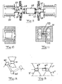
- Fig 2b It is schematically illustrated in Fig 2b how said second means is controlled by the control unit to move the main contact electrode 2 apart from the main contact electrode 1 at an instant determined to be appropriate for said transfer. Said first means 9 will then with a determined delay, such as in the order of 0.1-5 ms, move the auxiliary contact electrode 4 as shown in Fig 2c for transferring the switch to an open state with a sufficient insulation between the main contact electrodes.
- a transfer of the switch from an open state to a closed state may be started by moving the main contact electrodes 1, 2 slightly apart, whereupon the auxiliary contact electrode 4 is moved in between the main contact electrodes, whereupon these are moved towards each other while obtaining a sufficient pressure upon the auxiliary contact electrode located therebetween for obtaining a good contact with a low contact resistance and which may take a high current, such as in the order of some kA.
- Figs 4 and 5 illustrate two possible ways of obtaining the required movability of the auxiliary contact electrode for transferring the switch between said two states by moving this contact electrode.
- Fig 4 shows how the auxiliary contact electrode 4' may be connected to an axle 14, which may be rotated for moving the auxiliary contact electrode.
- Fig 5 shows how the auxiliary contact electrode 4" may have an elliptical shape and be rotated when the switch is to be transferred between said two states.
- FIG. 6 An electric switch according to an embodiment of the present invention will now be more in detail described while making reference to Figs 6-11 . It is shown in the exploded view in Fig 6 how the switch has two parallel first main contact electrodes 1 formed by conductor rails and accordingly also two second main contact electrodes 2 in the form of contact arms, which may be moved towards and away from the first contact electrodes by displacing a pull rod 15 connected to one end 16 of the respective contact arm.
- a torsion spring 17 is connected to the other end 18 of the respective contact arm while biasing this towards the first main contact electrodes for applying a contact pressure to auxiliary contact electrodes located between the main contact electrodes in the closed state of the switch. The tension of the torsion springs will be increased when the pull rod 15 is controlled for opening the switch.
- Fig 6 It is shown in Fig 6 how the two auxiliary contact electrodes 4 are arranged on a slid 19 movable along a substantially rectilinear path defined by guiding plates 20, 21. How this movement of the auxiliary contact electrodes is achieved will now be explained while making reference mainly to Fig 8 showing this more in detail.
- the auxiliary electrode contact slid 19 is provided with armature plates 22 on one end thereof, so that the slid may be fixed by means of permanent magnets 23 (see Fig 9 ) in the end position thereof assumed in the open state of the switch.
- the slid is accelerated from a first of these bi-stable end positions by being hit by a member 24 in the form of a hammer brought to be accelerated by sending a current through a Thomson coil 25 indicated in Fig 9 and for which only the seat 26 is shown in Fig 8 .
- the hammer 24 has substantially the same mass and by that the same mechanical impedance as the slid 19, so that substantially all the kinetic energy thereof is transferred to the slid when this is hit by the hammer.
- Means are also provided for braking the member 24, 27 once hit by the slid and this comprises a piece 29 loaded by springs 30 in a position shown in Fig 9 for being hit by the member 27.
- the piece 29 has substantially the same mechanical impedance as the respective member 24, 27, so that substantially all the kinetic energy thereof will be transferred to the piece 29.
- the piece 29 is in the form of an electrically conducting plate located in the pole gap between permanent magnets 31, 32, so that a magnet flux is directed substantially perpendicularly to the flat large surfaces thereof. This means that eddy currents will be induced in the plate 29 as soon as it starts to move, so that these eddy currents and said magnetic flux will interact and result in a braking force applied on the plate 29 being proportional to the velocity of the plate 29.
- the kinetic energy is absorbed by resistive heating of the plate 29 and by that completely without any mechanical wear, which would result if friction or the like was used instead.
- the switch is symmetric with respect to the members 24, 27, the function of said apparatus and the pieces 29 with brakes, so that the members are always in opposite bi-stable positions.
- the members 24, 27 are provided with bumping layers 33 on opposite sides thereof. These layers shall be of a material showing low inner energy losses and at the same time a high mechanical strength.
- a very fast electric switch is obtained by having the means for obtaining the movement of the auxiliary contact electrodes completely separated therefrom, so that the mass of these conduct electrodes with the slid 19 may be low and by that be given a very high acceleration.
- This means in practice that such an electric switch according to an embodiment of the invention may be transferred from one of the states to the other in less than 2 ms, and thanks to the braking of the eddy current brake the switch may be triggered to a state transfer again after about 10 ms.
- FIG. 12 A simulated acceleration of a hammer of the electric switch shown in Figs 6-11 versus time is shown in Fig 12 , in which XA is the acceleration, XV is the velocity and XP is the position of the hammer.
- Fig 13 illustrates a simulation of the velocity of the hammer XV, the velocity of the auxiliary conduct electrode slid YV when hit by the hammer at the instant 0 and F is the interaction force between the hammer and the slid versus time.
- FIG. 14 illustrates schematically how a hammer 40 may be connected to a rotatable rod 41, which may be brought to rotate for transfer of state of the switch by striking the hammer 40 against the auxiliary contact electrode 4.
- Several such hammers 40 may be connected to the same rotatable rod 41 for controlling a plurality of electric switches.
- Fig 15 illustrates very schematically an embodiment of an electric switch according to the invention, which has a first main contact electrode 1' in common to said first and second current paths and two second main contact electrodes 2', 2" configured to be arranged in one of said first and second current paths each.
- This embodiment comprises said first means configured to close one of said current paths when opening the other by moving the two auxiliary contact electrodes 4''', 4"" as shown in Fig 15 .
- Preferred uses of an electric switch according to the present invention is in tap changers, such as in on-load tap changers, in current limiters and in equipment for reactive power compensation, such as in Static Var Compensation (SVC) or in Controlled Series Capacitors (CSC).
- SVC Static Var Compensation
- CSC Controlled Series Capacitors
- AgSnO 2 and/or Ag are advantageous materials for the contact electrodes, since they are very resistant to welding at the voltages normally occurring when an electric switch of this type is controlled to switch.
- Said first means may be of other types than described above, such as utilizing magnetostriction or even explosives if it is a one way switch.
- the eddy current brake may be replaced by any other suitable brake, such as a pneumatic brake.
Landscapes
- Arc-Extinguishing Devices That Are Switches (AREA)
Priority Applications (1)
| Application Number | Priority Date | Filing Date | Title |
|---|---|---|---|
| EP09180362A EP2339599A1 (de) | 2009-12-22 | 2009-12-22 | Schalter und Verwendung dafür |
Applications Claiming Priority (1)
| Application Number | Priority Date | Filing Date | Title |
|---|---|---|---|
| EP09180362A EP2339599A1 (de) | 2009-12-22 | 2009-12-22 | Schalter und Verwendung dafür |
Publications (1)
| Publication Number | Publication Date |
|---|---|
| EP2339599A1 true EP2339599A1 (de) | 2011-06-29 |
Family
ID=42101452
Family Applications (1)
| Application Number | Title | Priority Date | Filing Date |
|---|---|---|---|
| EP09180362A Withdrawn EP2339599A1 (de) | 2009-12-22 | 2009-12-22 | Schalter und Verwendung dafür |
Country Status (1)
| Country | Link |
|---|---|
| EP (1) | EP2339599A1 (de) |
Cited By (1)
| Publication number | Priority date | Publication date | Assignee | Title |
|---|---|---|---|---|
| CN112713046A (zh) * | 2020-12-11 | 2021-04-27 | 平高集团有限公司 | 一种缓冲装置、操动机构及极速开断高压开关 |
Citations (8)
| Publication number | Priority date | Publication date | Assignee | Title |
|---|---|---|---|---|
| FR2333337A1 (fr) * | 1975-11-25 | 1977-06-24 | Merlin Gerin | Interrupteur electrique limiteur a coupure rapide |
| EP0017575A1 (de) * | 1979-04-09 | 1980-10-15 | Merlin Gerin | Schalter mit Schnellauslösung im Falle eines Fehlers |
| FR2512268A1 (fr) * | 1981-08-27 | 1983-03-04 | Merlin Gerin | Interrupteur electrique a commande rapide |
| EP0450104A1 (de) * | 1990-03-28 | 1991-10-09 | Siemens Aktiengesellschaft | Schnellschalter |
| WO2000022641A1 (de) * | 1998-10-09 | 2000-04-20 | Siemens Aktiengesellschaft | Mittelspannungsschalter |
| EP1067569A1 (de) * | 1999-07-06 | 2001-01-10 | ABB Hochspannungstechnik AG | Schnelle mechanische Schaltstelle |
| EP1098332A2 (de) | 1999-11-08 | 2001-05-09 | ABB Hochspannungstechnik AG | Schneller strombegrenzender Schalter |
| EP1538645A1 (de) * | 2003-12-05 | 2005-06-08 | Société Technique pour l'Energie Atomique TECHNICATOME | Hybrid-Leistungsschalter |
-
2009
- 2009-12-22 EP EP09180362A patent/EP2339599A1/de not_active Withdrawn
Patent Citations (8)
| Publication number | Priority date | Publication date | Assignee | Title |
|---|---|---|---|---|
| FR2333337A1 (fr) * | 1975-11-25 | 1977-06-24 | Merlin Gerin | Interrupteur electrique limiteur a coupure rapide |
| EP0017575A1 (de) * | 1979-04-09 | 1980-10-15 | Merlin Gerin | Schalter mit Schnellauslösung im Falle eines Fehlers |
| FR2512268A1 (fr) * | 1981-08-27 | 1983-03-04 | Merlin Gerin | Interrupteur electrique a commande rapide |
| EP0450104A1 (de) * | 1990-03-28 | 1991-10-09 | Siemens Aktiengesellschaft | Schnellschalter |
| WO2000022641A1 (de) * | 1998-10-09 | 2000-04-20 | Siemens Aktiengesellschaft | Mittelspannungsschalter |
| EP1067569A1 (de) * | 1999-07-06 | 2001-01-10 | ABB Hochspannungstechnik AG | Schnelle mechanische Schaltstelle |
| EP1098332A2 (de) | 1999-11-08 | 2001-05-09 | ABB Hochspannungstechnik AG | Schneller strombegrenzender Schalter |
| EP1538645A1 (de) * | 2003-12-05 | 2005-06-08 | Société Technique pour l'Energie Atomique TECHNICATOME | Hybrid-Leistungsschalter |
Non-Patent Citations (2)
| Title |
|---|
| MEYER J-M ET AL: "A DC Hybrid Cricuit Breaker With Ultra-Fast Contact Opening and Integrated Gate-Commutated Thyristors (IGCTs)", IEEE TRANSACTIONS ON POWER DELIVERY, IEEE SERVICE CENTER, NEW YORK, NY, US LNKD- DOI:10.1109/TPWRD.2006.870981, vol. 21, no. 2, 1 April 2006 (2006-04-01), pages 646 - 651, XP001546353, ISSN: 0885-8977 * |
| MEYER J-M: "A DC Hybrid Circuit Breaker With Ultra-Fast Contact Opening and Integrated Gate-Commutated Thyristors (IGCTs", IEEE TRANSACTIONS ON POWER DELIVERY, vol. 21, no. 1, April 2006 (2006-04-01), pages 646 - 651 |
Cited By (1)
| Publication number | Priority date | Publication date | Assignee | Title |
|---|---|---|---|---|
| CN112713046A (zh) * | 2020-12-11 | 2021-04-27 | 平高集团有限公司 | 一种缓冲装置、操动机构及极速开断高压开关 |
Similar Documents
| Publication | Publication Date | Title |
|---|---|---|
| RU2410783C2 (ru) | Электромагнитный исполнительный элемент управления, в частности, для выключателя среднего напряжения | |
| EP2312605B1 (de) | Bistabiler magnetischer Aktuator für einen Mittelspannungsschutzschalter | |
| TW200834628A (en) | Circuit breaker and opening and closing method thereof | |
| CN106449203B (zh) | 双电源不停电特快速切换装置 | |
| CN109036994A (zh) | 无极性微型断路器 | |
| CN104282497B (zh) | 电接触器 | |
| WO2014017241A1 (ja) | 開閉器 | |
| US11817258B2 (en) | Flexible thomson coil to shape force profile/multi-stage thomson coil | |
| CN104303251A (zh) | 线路保护开关 | |
| WO2013013984A1 (en) | Method for driving an actuator of a circuit breaker, and actuator for a circuit breaker | |
| US10032589B2 (en) | Actuating apparatus for a vacuum interrupter and disconnecting arrangement | |
| CN116798804A (zh) | 一种中压快速机械开关及分合闸方法 | |
| US7482902B2 (en) | Linear magnetic drive | |
| CN101901718A (zh) | 配双稳态永磁操动机构的直动式真空断路器 | |
| EP2339599A1 (de) | Schalter und Verwendung dafür | |
| US20220139654A1 (en) | Thomson coil with energized coil damping | |
| US9679727B2 (en) | Switch assembly | |
| TWI351705B (de) | ||
| Lammers et al. | MV vacuum switchgear based on magnetic actuators | |
| US20150270766A1 (en) | Scalable, Highly Dynamic Electromagnetic Linear Drive With Limited Travel And Low Transverse Forces | |
| CN209822486U (zh) | 一种快速开关的通断机构和快速开关 | |
| WO2016106917A1 (zh) | 一种永磁驱动有载调压开关 | |
| Jian et al. | Simulation analysis and design of a high speed mechanical contact base on electro-magnetic repulsion mechanism | |
| CN114097054B (zh) | 断路器 | |
| JP2021500730A (ja) | 瞬間的な高電流の影響に対して耐性を有する高電圧リレー |
Legal Events
| Date | Code | Title | Description |
|---|---|---|---|
| PUAI | Public reference made under article 153(3) epc to a published international application that has entered the european phase |
Free format text: ORIGINAL CODE: 0009012 |
|
| AK | Designated contracting states |
Kind code of ref document: A1 Designated state(s): AT BE BG CH CY CZ DE DK EE ES FI FR GB GR HR HU IE IS IT LI LT LU LV MC MK MT NL NO PL PT RO SE SI SK SM TR |
|
| 17P | Request for examination filed |
Effective date: 20111229 |
|
| STAA | Information on the status of an ep patent application or granted ep patent |
Free format text: STATUS: THE APPLICATION HAS BEEN WITHDRAWN |
|
| 18W | Application withdrawn |
Effective date: 20121018 |