EP2339374A2 - Procédé de détection d'objet et agencement associé des transducteurs - Google Patents
Procédé de détection d'objet et agencement associé des transducteurs Download PDFInfo
- Publication number
- EP2339374A2 EP2339374A2 EP10192353A EP10192353A EP2339374A2 EP 2339374 A2 EP2339374 A2 EP 2339374A2 EP 10192353 A EP10192353 A EP 10192353A EP 10192353 A EP10192353 A EP 10192353A EP 2339374 A2 EP2339374 A2 EP 2339374A2
- Authority
- EP
- European Patent Office
- Prior art keywords
- transducers
- objects
- environment
- vehicle
- pulses
- Prior art date
- Legal status (The legal status is an assumption and is not a legal conclusion. Google has not performed a legal analysis and makes no representation as to the accuracy of the status listed.)
- Withdrawn
Links
Images

Classifications
-
- G—PHYSICS
- G01—MEASURING; TESTING
- G01S—RADIO DIRECTION-FINDING; RADIO NAVIGATION; DETERMINING DISTANCE OR VELOCITY BY USE OF RADIO WAVES; LOCATING OR PRESENCE-DETECTING BY USE OF THE REFLECTION OR RERADIATION OF RADIO WAVES; ANALOGOUS ARRANGEMENTS USING OTHER WAVES
- G01S15/00—Systems using the reflection or reradiation of acoustic waves, e.g. sonar systems
- G01S15/88—Sonar systems specially adapted for specific applications
- G01S15/93—Sonar systems specially adapted for specific applications for anti-collision purposes
- G01S15/931—Sonar systems specially adapted for specific applications for anti-collision purposes of land vehicles
-
- G—PHYSICS
- G01—MEASURING; TESTING
- G01S—RADIO DIRECTION-FINDING; RADIO NAVIGATION; DETERMINING DISTANCE OR VELOCITY BY USE OF RADIO WAVES; LOCATING OR PRESENCE-DETECTING BY USE OF THE REFLECTION OR RERADIATION OF RADIO WAVES; ANALOGOUS ARRANGEMENTS USING OTHER WAVES
- G01S15/00—Systems using the reflection or reradiation of acoustic waves, e.g. sonar systems
- G01S15/02—Systems using the reflection or reradiation of acoustic waves, e.g. sonar systems using reflection of acoustic waves
- G01S15/06—Systems determining the position data of a target
- G01S15/08—Systems for measuring distance only
- G01S15/10—Systems for measuring distance only using transmission of interrupted, pulse-modulated waves
- G01S15/101—Particularities of the measurement of distance
-
- G—PHYSICS
- G01—MEASURING; TESTING
- G01S—RADIO DIRECTION-FINDING; RADIO NAVIGATION; DETERMINING DISTANCE OR VELOCITY BY USE OF RADIO WAVES; LOCATING OR PRESENCE-DETECTING BY USE OF THE REFLECTION OR RERADIATION OF RADIO WAVES; ANALOGOUS ARRANGEMENTS USING OTHER WAVES
- G01S15/00—Systems using the reflection or reradiation of acoustic waves, e.g. sonar systems
- G01S15/87—Combinations of sonar systems
-
- G—PHYSICS
- G01—MEASURING; TESTING
- G01S—RADIO DIRECTION-FINDING; RADIO NAVIGATION; DETERMINING DISTANCE OR VELOCITY BY USE OF RADIO WAVES; LOCATING OR PRESENCE-DETECTING BY USE OF THE REFLECTION OR RERADIATION OF RADIO WAVES; ANALOGOUS ARRANGEMENTS USING OTHER WAVES
- G01S7/00—Details of systems according to groups G01S13/00, G01S15/00, G01S17/00
- G01S7/52—Details of systems according to groups G01S13/00, G01S15/00, G01S17/00 of systems according to group G01S15/00
- G01S7/523—Details of pulse systems
- G01S7/526—Receivers
- G01S7/527—Extracting wanted echo signals
-
- G—PHYSICS
- G01—MEASURING; TESTING
- G01S—RADIO DIRECTION-FINDING; RADIO NAVIGATION; DETERMINING DISTANCE OR VELOCITY BY USE OF RADIO WAVES; LOCATING OR PRESENCE-DETECTING BY USE OF THE REFLECTION OR RERADIATION OF RADIO WAVES; ANALOGOUS ARRANGEMENTS USING OTHER WAVES
- G01S13/00—Systems using the reflection or reradiation of radio waves, e.g. radar systems; Analogous systems using reflection or reradiation of waves whose nature or wavelength is irrelevant or unspecified
- G01S13/88—Radar or analogous systems specially adapted for specific applications
- G01S13/93—Radar or analogous systems specially adapted for specific applications for anti-collision purposes
- G01S13/931—Radar or analogous systems specially adapted for specific applications for anti-collision purposes of land vehicles
- G01S2013/9314—Parking operations
-
- G—PHYSICS
- G01—MEASURING; TESTING
- G01S—RADIO DIRECTION-FINDING; RADIO NAVIGATION; DETERMINING DISTANCE OR VELOCITY BY USE OF RADIO WAVES; LOCATING OR PRESENCE-DETECTING BY USE OF THE REFLECTION OR RERADIATION OF RADIO WAVES; ANALOGOUS ARRANGEMENTS USING OTHER WAVES
- G01S13/00—Systems using the reflection or reradiation of radio waves, e.g. radar systems; Analogous systems using reflection or reradiation of waves whose nature or wavelength is irrelevant or unspecified
- G01S13/88—Radar or analogous systems specially adapted for specific applications
- G01S13/93—Radar or analogous systems specially adapted for specific applications for anti-collision purposes
- G01S13/931—Radar or analogous systems specially adapted for specific applications for anti-collision purposes of land vehicles
- G01S2013/9317—Driving backwards
-
- G—PHYSICS
- G01—MEASURING; TESTING
- G01S—RADIO DIRECTION-FINDING; RADIO NAVIGATION; DETERMINING DISTANCE OR VELOCITY BY USE OF RADIO WAVES; LOCATING OR PRESENCE-DETECTING BY USE OF THE REFLECTION OR RERADIATION OF RADIO WAVES; ANALOGOUS ARRANGEMENTS USING OTHER WAVES
- G01S13/00—Systems using the reflection or reradiation of radio waves, e.g. radar systems; Analogous systems using reflection or reradiation of waves whose nature or wavelength is irrelevant or unspecified
- G01S13/88—Radar or analogous systems specially adapted for specific applications
- G01S13/93—Radar or analogous systems specially adapted for specific applications for anti-collision purposes
- G01S13/931—Radar or analogous systems specially adapted for specific applications for anti-collision purposes of land vehicles
- G01S2013/9324—Alternative operation using ultrasonic waves
-
- G—PHYSICS
- G01—MEASURING; TESTING
- G01S—RADIO DIRECTION-FINDING; RADIO NAVIGATION; DETERMINING DISTANCE OR VELOCITY BY USE OF RADIO WAVES; LOCATING OR PRESENCE-DETECTING BY USE OF THE REFLECTION OR RERADIATION OF RADIO WAVES; ANALOGOUS ARRANGEMENTS USING OTHER WAVES
- G01S13/00—Systems using the reflection or reradiation of radio waves, e.g. radar systems; Analogous systems using reflection or reradiation of waves whose nature or wavelength is irrelevant or unspecified
- G01S13/88—Radar or analogous systems specially adapted for specific applications
- G01S13/93—Radar or analogous systems specially adapted for specific applications for anti-collision purposes
- G01S13/931—Radar or analogous systems specially adapted for specific applications for anti-collision purposes of land vehicles
- G01S2013/9327—Sensor installation details
- G01S2013/93275—Sensor installation details in the bumper area
-
- G—PHYSICS
- G01—MEASURING; TESTING
- G01S—RADIO DIRECTION-FINDING; RADIO NAVIGATION; DETERMINING DISTANCE OR VELOCITY BY USE OF RADIO WAVES; LOCATING OR PRESENCE-DETECTING BY USE OF THE REFLECTION OR RERADIATION OF RADIO WAVES; ANALOGOUS ARRANGEMENTS USING OTHER WAVES
- G01S15/00—Systems using the reflection or reradiation of acoustic waves, e.g. sonar systems
- G01S15/88—Sonar systems specially adapted for specific applications
- G01S15/93—Sonar systems specially adapted for specific applications for anti-collision purposes
- G01S15/931—Sonar systems specially adapted for specific applications for anti-collision purposes of land vehicles
- G01S2015/937—Sonar systems specially adapted for specific applications for anti-collision purposes of land vehicles sensor installation details
- G01S2015/939—Sonar systems specially adapted for specific applications for anti-collision purposes of land vehicles sensor installation details vertical stacking of sensors, e.g. to enable obstacle height determination
Definitions
- the invention relates to an environment detection for vehicles, in particular by means of ultrasound.
- the invention relates in particular to an object-related environment identification and presentation.
- transducers It is known to attach transducers to the outer sides of vehicles, to emit ultrasonic pulses into the environment by means of these transducers and to close objects in the surroundings by means of the reflected sound waves.
- the methods provided in the prior art are reduced to information that is sensor related and that indicates whether or not one or more objects are within range and within the orientation of a particular transducer, but without distinguishing number or type of objects. Therefore, according to the prior art, if only one reflection (or even several) is detected, then general information is output, according to which obstacles are present within the reception range of a transducer without providing further information.
- the evaluation related to the range of a converter offers only limited information about object arrangements in the environment.
- surround detections according to the prior art are related to a direction of travel and therefore only provide information as to whether an object would be hit while maintaining a certain direction of travel or not.
- the concept underlying the invention is to detect objects in a driving environment more specifically by means of ultrasound by detecting object data not only in one plane but at different heights relative to the driving plane of the vehicle. Therefore, the invention particularly relates to ultrasound-based detection in which a plurality of sensors not only extend in a plane parallel to the driving plane (and have the same azimuthal angle), but ultrasonic reflection measurements with different (azimuthal) orientations are carried out in a targeted manner in the direction of the normal driving plane (ie perpendicular to the driving plane).
- the driving plane of the vehicle is the plane in which the four points lie, which represent the contact points between the wheels of the vehicle and the ground.
- Another aspect of the invention is object classification enabled by the additional data.
- an object is scanned by the different orientations in at least two different heights, so that it is possible to give clearly more precise information about the extent or the acoustic properties of the object than in comparison to the prior art, in which it was only detected that within a transducer detection area reflections that suggest obstacles.
- object detection data that differs in the direction of the car's normal, but corresponds to substantially the same (two-dimensional) location, allow individual detected object elements by comparing their ultrasonically acquired properties to each other and to conclude from the similarity of the individual object elements that they belong to the same object. This creates a resolution of the objects into individual object elements, which significantly increases the precision of the environmental detection.
- the individual data collected on the object elements can be correlated by a variety of physical magnitudes, such as motion, distance, orientation, signal strength, time of flight, or the like, so that there is a large amount of data available from a single ultrasound measurement to correlate the object elements can be determined and based on this correlation, whether or not the object elements belong to that object.
- the increased precision allows the objects to be spatially separated from one another so that the increased resolution of the environmental detection leads to a more precise representation of the environment with regard to the type and location of the objects.
- the three-dimensional resolution allows much more precise and significant environmental information, even if the same number of transducers as used in the two-dimensional case are used.
- the method according to the invention for the individual detection of objects in an environment of a vehicle provides that first several transmit pulses are sent into the environment by means of a plurality of transducers, and these are received as receive pulses after transmission and reflection by the environment.
- first several transmit pulses are sent into the environment by means of a plurality of transducers, and these are received as receive pulses after transmission and reflection by the environment.
- reflection components within the received pulses which are provided by the individual reflections on the objects.
- a received pulse is thus not only associated with a single object, but the received pulse is examined on the basis of reflection components that are associated with the reflection of a transmission pulse to an object.
- a multiplicity of reflection components within one receive pulse thus results.
- the steps of receiving and despatching with orientations concerning the transducer relate to a major axis of the directivity of the transducers that occurs during reception and transmission.
- the orientations differ in the direction of the driving plane normal of the driving plane of the vehicle.
- the vehicle plane normal corresponds essentially to a vertical direction, perpendicular to the horizontal and along the direction of action of the gravitation.
- the individual object elements of the objects in the environment are detected according to the invention, preferably by evaluating the individual reflection components.
- the object elements are distinguished by the reflection components.
- An object can be provided by one or more object elements, wherein the individual object elements are subdivided according to the resolution during the object detection, or can be distinguished on the basis of the reflection components within corresponding reception pulses.
- the fact that the orientations differ in the direction of the car plane normal results in a resolution in the height direction, the detection being provided for a plurality of zones into which the environment is divided, and a plurality of zones being different due to the resolution in the direction of the car plane normal , For different heights or azimuthal angles, therefore, the resolution results in several different zones, but at least two in order to obtain additional altitude information.
- a vehicle can only move along the driving plane and therefore a two-dimensional resolution initially appears sufficient, the resolution in the third dimension allows a more precise object assignment or object detection, since more information about the environment is provided.
- the orientation of the transducers is differentiated in the direction of the driving plane normal that they are offset from one another either in the direction of the normal driving plane. Since the orientation of the transducer depends on the position of the transducer, a reference point for each transducer results, which essentially represents the location of the transducer or transducer membrane. The orientation is thus not only a direction vector, but comprises a three-dimensional location representation including a reference point, from which the directional lobe of the transducer represents the directional sensitivity. The reference point of the transducer is therefore the height along the driving plane normal, preferably including the information of the other two spatial dimensions.
- the orientations of the transducers can be inclined in the direction of the driving plane normal to each other. Therefore, the orientations of the transducers and the orientations of the respective directivity characteristics are inclined to each other according to an azimuthal angle as far as the azimuthal angle refers to the driving plane.
- the transmission pulses are transmitted from the outside of the vehicle and also received from this outside of the vehicle.
- the location of the transmission or reception is the location of the transducers, so that the transducers in this method are located on the outside of the vehicle. Therefore, the transducers are arranged at different heights of the vehicle, i. offset each other in the direction of the normal driving plane.
- a different inclination between the transducers may be provided by having different orientations with respect to the outside of the vehicle, the inclination differing in the direction of the vehicular plane normal. This defines the location and orientation of the transmission and reception since the transmission or reception alignment is directly linked to the orientation of the transducer.
- the environment is resolved in three spatial dimensions. This resolution results in several three-dimensional zones.
- the three spatial dimensions form a Cartesian coordinate system.
- One of the space dimensions is provided by the car's normal, i. for example, the z-axis of the coordinate system. Angles to this z-axis are therefore called the azimuthal angle.
- object elements present there are detected.
- the resolution of the environment in three spatial dimensions therefore includes a resolution in the direction of the driving plane normal, so that the zones are also distinguished in the direction of the driving plane normal.
- the object elements of the environment are detected by detecting object classes of the object elements into which the objects are classified according to different types of objects. Instead, or preferably in combination with, an accuracy value for the object elements, ie for the individual subdivided object elements, is detected, the accuracy value representing the estimator quality.
- an accuracy value for the object elements ie for the individual subdivided object elements
- object elements detected per zone or object element detected per zone are provided with an accuracy value that determines the probability indicates that the object element actually exists there and thus the detection is correct. This probability depends, for example, on the signal strength or can be provided on the basis of the signal strength, with high signal strengths representing a high estimator quality, and low signal strengths representing a low estimator quality.
- the link between signal strength and estimator can be provided proportionally in a particularly simple embodiment, or in principle by means of a monotonically or preferably strictly monotonically increasing function, which assigns a signal strength of an estimator.
- object elements are detected in which physical properties of the object elements are detected. These physical properties can also be used for the object classification described above and for the acquisition of the accuracy value or the estimator quality. Based on the physical properties of individual object elements, these can be compared with each other and, with great similarity, linked together to form an object. Object elements with different physical properties are therefore assigned to different objects, and object elements with similar physical properties are assigned the same path, preferably as far as their position reflects a coherent object or a specific object pattern.
- the signal strength described above, from which the estimator quality is determined, which in turn can be sent to detect the similarity of object elements, can also be used directly to close the same object at similar signal strengths of different object elements, and at different signal strengths, the object elements close different objects.
- physical properties of the object elements are detected in order to conclude by their comparison on the similarity of object elements and thus to assign the same object.
- the period duration deviation relates to a length of the received pulse, ie based on the envelope of the received pulse, compared with the period of the transmit pulse.
- the period duration is shortened due to the Doppler shift, and extends as the object moves away from the converter.
- the signal pulse is compressed or stretched by the reflection to an object that moves relative to each other according to the relative movement.
- properties of the object element can be provided, which result from evaluation of the received pulse.
- properties include, for example, the location of the object element resulting, for example, by transit time measurements.
- properties are the result of evaluation speed, acceleration and / or direction of movement of the object element.
- Speed, acceleration and direction of movement can be detected, for example, by means of the Doppler shift or by means of successive location measurements.
- Further properties of the object element, which result from evaluations can be provided by the transducer, with which the object or the object element was detected.
- the identification of the associated transducer can be directly concluded that its directional characteristic, so that when an object element has been detected by the transducer, so that it was also detected that the object element is present within the sensor range of the transducer.
- the environment can be divided into sections, so that when the associated transducer has been detected, also a location determination of the object element is provided, in which it is assumed that the object element resides within the detection range of the transducer.
- the location of the converter can thereby be provided as a property of the object element with which the object element was detected.
- the location of the transducer refers to a location relative to the vehicle, such as an outside of the vehicle, such as a corner or a particular side surface.
- a property of the object element is also provided when an object element is detected by the transducer located at a particular location.
- Another property that results from evaluations of the received pulse is the transmission time when the transmission pulses are not delivered simultaneously but offset from each other by the various transducers. On the basis of the transmission time can be closed to the converter, since they are time encoded due to the output sequence or are distinguishable. This is provided when several transducers emit the transmission pulses sequentially, so that it is possible to conclude the identity and thus the location of the converter solely on the basis of the time of reception.
- object classification In a further classification or scheduling variant, it is provided that the similarity of object elements is provided on the basis of an object classification.
- object types are classified on the basis of physical properties. Object elements with similar physical properties are divided into the same object class, and object elements with different physical properties are divided into different object classes. Classifications or object types can be assigned to the directly acoustic properties and the properties provided by the evaluation. For example, when detecting a Doppler shift, it can be concluded that the object element belongs to the object class "moving vehicle". Similarly, whether the object type "wall" is correct or whether an object class representing a plurality of distributed object elements is appropriate, for example, a plurality of bars, can be detected based on the signal strength or the number of echoes.
- the method therefore also includes determining a similarity of the object elements based on the properties or on the types of objects or object classes that were detected for the object elements, wherein a plurality of object elements can also be correlated with each other or jointly provide a similarity with an object pattern.
- a similarity of the object elements based on the properties or on the types of objects or object classes that were detected for the object elements, wherein a plurality of object elements can also be correlated with each other or jointly provide a similarity with an object pattern.
- several captured object elements are combined into one object, so that in a further processing or display of the environment, only the composite object, but not the object elements, must be reproduced or processed.
- the acoustic properties can be instantaneous recordings of the surroundings, whereby the assignment to objects takes place on the basis of the instantaneous recordings.
- multiple consecutive snapshots may be made in accordance with the invention that result in successive object detections, for example, to detect that an object element performs a similar motion as another object element according to the history thus detected. Due to this similarity, the similarly moving object elements can be assigned to a moving object. This motion-based detection is based on the repeated enclosing of the environment and the object elements present there.
- the temporal offset between the snapshots and the successive plurality of snapshots can be considered as a "film" that results for the environment and allows further inferences on the association of different object elements with objects. Basically, it applies here that differently moving object elements can not be assigned to the same object, and similarly moving objects, for example at the same speed, can be assigned to the same object.
- the time window is associated with a single environment detection, and the multiple pulses serve to further dissolve the environment.
- the resolution is provided as spatial resolution.
- the sending and the receiving are repeated for each of the plurality of pulses Therefore, the time window in which the plurality of pulses repeating the reception and transmission of multiple pulses as a sequence of environment acquisitions, thereby rendering the objects one resolution
- the temporal resolution results from the repetition of the time windows and the time interval between the time windows, wherein it is to be expected during the time interval that the environment changes at least slightly (for example if a a relative movement to the vehicle takes place), whereby movements can be represented as "film”.
- object elements of individual zones are assigned to a common object on the basis of similar detection features of the object elements.
- the detection features correspond to the detection features or object classes or feature types presented above.
- the detection features include distance, direction, transit time, period duration deviation, Doppler shift, movement history, speed, acceleration, direction of movement, associated sensor or transducer with which the object elements were detected, transmission time, the sequential transmission of the transmission pulses through the plurality of transducers a specific transducer or transducer location, or object classification.
- object elements are compared with one another, and combined with or assigned to a common object with a certain similarity.
- the assignment can be provided, for example, by a threshold value comparison, by correlation or by a common affiliation or similarity to a predefined pattern of an object type.
- a predefined pattern of an object type can be represented by typical value intervals, so that when the detection features of the transducers fall within these intervals, the object is considered to belong to the object type.
- the object type of the object is determined, and the object itself is provided by merging the object element according to the predetermined pattern.
- the method according to the invention is based on a three-dimensional resolution of the surroundings of a vehicle, wherein the resolution is provided by ultrasound transducers having different orientations, in particular orientations which differ in the direction of the car plane normal.
- the resolution is provided by zones that completely fill the room. The zones can therefore have a constant size.
- this requires a relatively high processing effort, without this would result in an accuracy advantage. Therefore, it is preferably provided that the resolution is not constant and decreases with the distance to the vehicle.
- the basis for this is that near objects or object elements can in principle be resolved better spatially than object elements located remotely, this being a result of the decreasing signal-to-noise ratio with increasing distance.
- the resolution is not made constant depending on the arrangement of the zone to a driving corridor.
- a driving corridor may be estimated by means of traffic measures or objects, for example by means of processing the objects which are detected by means of ultrasound or by processing optical data of a vehicle-protected camera, or a combination thereof.
- video camera images that capture the traffic environment and in particular traffic measures such as lane markings are used to represent the driving corridor.
- the travel corridor can be adjusted based on objects within the environment, for example other road users, for example moving vehicles.
- the travel corridor has border areas that reflect the corridor outer edge. In these peripheral areas, the resolution is greater than in the interior of the driving corridor or as outside areas of the driving corridor. The larger resolution can be reproduced by reducing the size of the zones.
- the travel corridor itself can be defined in two spatial dimensions, preferably in the driving plane of the vehicle.
- the travel corridor may be defined in three spatial dimensions, with additional altitude information being added, i. Information according to a resolution in the direction of the driving plane normal, wherein objects or object elements near the driving plane are distinguished from objects near the middle of the vehicle, which in turn are distinguished from objects or object elements above the vehicle or above the vehicle center.
- the estimator quality can be taken into account, whereby object elements with a low estimator quality are considered less in the assignment to an object than object elements with a high estimator quality.
- previously executed object captures are taken into account in successive instantaneous captures, in particular in the assignment of the object elements in subsequent snapshots.
- the association may also be performed by filtering the associated sensed characteristics, the filtering allowing similar object elements associated with a particular object to pass on the same physical properties, while distinguishing them from the object elements of another object.
- these properties are averaged and assigned to the object.
- velocities detected for different object elements but similar and thus assigned to the same path may, for example, be averaged and the mean assigned to the object.
- all of the above-mentioned properties i.e., physical properties or properties resulting from evaluation of the physical properties
- the object thus assigned then obtains the mean value of the properties of the individual object elements.
- the individual properties are weighted on the basis of the estimator quality, wherein a high estimator quality leads to a strong consideration, i. gives a high weighting of the associated property in the averaging, and a low estimation quality leads to a small consideration of the property in averaging.
- the weighting can be provided in particular as a directly proportional weighting.
- the invention is further provided by an arrangement of transducers adapted to deliver and receive ultrasonic pulses, the arrangement of transducers providing that the transducers are not only differently oriented in one direction (for example in the horizontal direction), but also also in a direction perpendicular thereto (ie vertical direction), which, however, differs from the propagation direction of the transducer.
- the arrangement may be arranged for attachment to a vehicle, which is not part of the arrangement.
- a driving plane is defined for the vehicle, which also applies to the arrangement, although the vehicle is not part of the arrangement.
- the arrangement may be defined in terms of its orientation on the basis of the driving plane, in which the transmission and reception orientations of the transducers differ in the direction of a driving plane normal of the driving plane.
- the arrangement of the transducers may be further defined without reference to a vehicle, wherein the transducers are oriented differently in two different directions, both directions being perpendicular or at least inclined to a main propagation direction of the transducers, which are the main propagation direction (ie, mean propagation direction) of sound waves which are radiated from the transducers.
- This arrangement of the transducer automatically results in a three-dimensional resolution, since the orientations the converter in an actual solid angle (horizontal angle and azimuthal angle nonzero) differ.
- the distinction may, as already described above with reference to the method, be provided either by dislocation, by different inclination or by both.
- the transducers may be offset from one another by the arrangement of the plane of the plane normal, or the transducers may be inclined to the plane of travel normal by arrangement with different orientation angles. Further, the transducers may be offset from one another in the direction of the normal plane of travel, as well as inclined at different orientation angles to the plane of the vehicle.
- the arrangement of the transducers provides an offset or an inclination (or both) in one direction that is perpendicular to another direction, but both directions are perpendicular to the main propagation direction of the sound waves. Both directions thus represent an offset or tilt in two directions, which, together with depth information, span a three-dimensional space.
- the three zones therefore concern objects provided (a) above the vehicle, (b) in front of the vehicle (but outside the travel corridor outside time) and (c) object elements provided below the vehicle itself, however Reason the ground clearance of the vehicle are passable. On the basis of these data, it is possible to make significantly more precise statements about passability or to take measures adapted to the situation (for example triggering of ABS or airbag, initiation of a braking process or the like).
- the properties as well as the estimator quality or the accuracy value are specified as discrete values and in particular
- the estimator quality is represented by a few discrete values, for example by four values associated with each object element or zone.
- the invention is further provided by methods comprising the use of the above-mentioned arrangement or the execution of the method described above, wherein it is further provided that based on the detected objects either object data are output for visual display, when detecting critical data warnings safety measures such as the deployment of airbags, the commencement of deceleration maneuvers, an intervention in the steering or possibly an acceleration of the vehicle.
- object data can be displayed to the driver by means of a perspective representation of the environment, the individual objects being reproduced, for example, by means of simple symbols which are formed according to the properties.
- the environment may be represented by a plan view, or merely by numerical data or the like.
- the individual objects or object elements can be reproduced by simple geometric shapes such as sphere, cylinder or surface.
- the arrangement according to the invention which is also used in the context of the method according to the invention, arranges the transducers in an at least two-dimensional surface which is perpendicular or inclined with respect to all main radiation directions of the transducers or main reception directions of the transducers (defined by their directivity). While in the prior art, the transducers are arranged in a line, and all directional characteristics in the same or in parallel directions, the arrangement provides not only to offset the directional characteristics in parallel along a line (which is parallel to a driving plane) but to incline toward each other at a solid angle that differs from an angle that runs in a plane that is parallel to the driving plane. Instead of or in combination with a different arrangement of the transducer itself, they may have such a tendency.
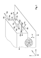
- FIG. 1 a vehicle 10 is shown, which is arranged on a driving plane 12.
- the figure also shows schematically the arrangement of transducers 20a, b, c, d with the respective directional characteristics, which are shown simplified in the form of their main lobe or their main lobe.
- the directional characteristics 22a-d are shown according to their sensitivity or emission signal strength as a function of the angle. Further, each directional characteristic 22a-d includes an associated orientation 24a-d representing the direction of maximum sensitivity and maximum radiation, respectively.
- the transducers 22a, b are disposed along a line 30 which is parallel to the driving plane 12
- the transducers 20c, d are offset from one another in a direction 40 which is perpendicular to the driving plane but may be generally inclined to the driving plane.
- the distance 40 corresponds to an offset that allows the three-dimensional resolution along the z-axis.
- the main direction 24c, d are offset from one another in the direction of the normal plane 12 'of the driving plane 12.
- the transducers 20c and 20d can also be mutually offset in the direction of the line 30, ie along the y-axis, or their directional characteristics 24c, d can have an additional inclination in the direction of the y-axis.
- the transducers 20a, b further enable three-dimensional resolution in the z-axis direction, although they do not have an offset in the z-axis direction, in which the main directions 24a, b or their directional characteristics 22a, b are inclined by angles 26a, b to the x -Axis (which runs parallel to the driving plane 12) are inclined differently.
- the angles 26a, b are chosen only by way of example and may have any orientation as long as the inclinations to the driving plane 12 are different.
- the x and y axes span the driving plane, with the z-axis extending in the direction of the travel plane normal 12 '.
- the transducers are in the FIG. 1 for reasons of clarity in the same plane.
- the plane ie the rear side of the vehicle 10
- the plane may correspond to a curved surface, so that solely due to the bending of the surface in which the transducers are arranged, they have mutually different directional characteristics.
- the transducers 20c, d may have different directional characteristics because their surface portion, on which they are mounted, bent (or curved) and despite the same relative arrangement of the respective transducers c, d to the ground due to the bending or curvature of the mounting surface they have a different orientation, to different main directions 24c, d in the direction of the driving plane normal 12 'leads.
- FIG. 2 shows the resolution of the zones relative to the vehicle 110 in plan view.
- Transducers 120 are disposed at the rear of the vehicle.
- the number and the arrangement of the converter is shown only by way of example.
- the result is a resolution in zones, the zones increase with increasing distance x from the transducers or from the vehicle in their length (measured in the x direction) and in their width (measured in the y direction).
- the z-axis is perpendicular to the plane of the drawing, so that the additional three-dimensional resolution from the figure is not immediately apparent.
- FIG. 2 arrangements can be used as described above, in particular the arrangement of FIG. 1 ,
- the width 160 of the zones 170 increases.
- the length 180 of the zones 170 increases.
- the area also increases with increasing x, in particular the volume, assuming similar size increases for the zone size in the z-direction (ie its height) as for the length 160 and the width 180.
- the zones are discretely divided and completely fill at least one sector of the environment.
- the zoning directly on the transducers 120 may be provided by the number of transducers and their signal processing. The division into FIG. 2 however, the transducers 120 are shown by way of example only and in a symbolic manner.
- FIG. 2 Furthermore, two objects 200, 210 are shown, each of which is divided into several zones.
- object 200 there are echoes that indicate object elements 200a-c.
- the zones in which the object elements 200a-c have been detected have a similar Doppler shift or similar pulse duration shortening or extension so that it can be assumed that the individual object elements 200a-c are moving at a similar speed. Since the object elements 20a-c belong to the same object 200, they actually move at exactly the same speed, but the discretization and measurement spreads merely give a similarity for the movement, for example a difference for the Doppler shift of +/- 5%.
- the object 200 is used in the following instead of the individual objects 200a-c.
- the associated signal strengths are also determined, the object element 200c generating a lower signal strength than the object elements 200a-b due to the greater distance. Therefore, the object element or zone 200c is assigned a lower estimator quality than the object elements 200a, b.
- the object elements 200a-c are not represented as elements of the object 200 itself, but already in the discretized resolution as shown in FIG FIG. 2 is shown.
- the object elements (210a, b) are detected, but which have substantially the same Doppler shift, namely zero. Due to the Doppler shift, it is concluded that the object (210) is not moving relative to the vehicle (110). Furthermore, similar signal strengths are detected for the object elements (210a, b), since they have approximately the same distance to the vehicle. The similarity of physical properties (i.e., Doppler shift and signal strength) is reflected in these physical properties. Therefore, to compare whether the object (210a) is similar to the object (210b), first a first physical quantity (i.e., Doppler shift) and then a second physical quantity (i.e., signal strength) may be compared, combining the comparison results.
- a first physical quantity i.e., Doppler shift
- a second physical quantity i.e., signal strength
- the object elements (210a, b) have substantially the same duration (and thus the same location determination).
- the velocity calculated for the individual elements 200a-c), (210a, b) may also be used to determine the physical (ie Property to check the similarity of the properties.
- object element 200b of object element 210a must be distinguished on the one hand from the different Doppler shift (object 200 and 210 have different speeds on the other hand, due to the specific transducers 120 which detect the received pulses belonging to the individual elements.
- object elements can also be assigned to the same object if they are detected by the same converter (for example in combination with a similar runtime).
- the top converter of the back converters 120 detects the object elements 200a, b, for example, but not the object element 210a due to the orientation.
- different object elements can be distinguished and assigned to different objects.
- all or a group of the properties or criteria with which the elements can be assigned can be combined with one another, for example combining weights, wherein the weighting can depend on the type of physical property or categorization or on the estimator quality, which in turn from the signal strength.
Landscapes
- Engineering & Computer Science (AREA)
- Radar, Positioning & Navigation (AREA)
- Remote Sensing (AREA)
- Physics & Mathematics (AREA)
- Computer Networks & Wireless Communication (AREA)
- General Physics & Mathematics (AREA)
- Acoustics & Sound (AREA)
- Measurement Of Velocity Or Position Using Acoustic Or Ultrasonic Waves (AREA)
Applications Claiming Priority (1)
| Application Number | Priority Date | Filing Date | Title |
|---|---|---|---|
| DE102009054663A DE102009054663A1 (de) | 2009-12-15 | 2009-12-15 | Verfahren zur Objekterfassung und Wandleranordnung hierfür |
Publications (2)
| Publication Number | Publication Date |
|---|---|
| EP2339374A2 true EP2339374A2 (fr) | 2011-06-29 |
| EP2339374A3 EP2339374A3 (fr) | 2013-03-27 |
Family
ID=43875379
Family Applications (1)
| Application Number | Title | Priority Date | Filing Date |
|---|---|---|---|
| EP10192353A Withdrawn EP2339374A3 (fr) | 2009-12-15 | 2010-11-24 | Procédé de détection d'objet et agencement associé des transducteurs |
Country Status (3)
| Country | Link |
|---|---|
| EP (1) | EP2339374A3 (fr) |
| CN (1) | CN102162849B (fr) |
| DE (1) | DE102009054663A1 (fr) |
Cited By (3)
| Publication number | Priority date | Publication date | Assignee | Title |
|---|---|---|---|---|
| WO2012031957A1 (fr) * | 2010-09-07 | 2012-03-15 | Valeo Schalter Und Sensoren Gmbh | Ensemble capteur à ultrasons pour un véhicule automobile comprenant un capteur à ultrasons central appliqué de manière excentrée par rapport au milieu du véhicule et à azimut incliné dans sa caractéristique de rayonnement |
| WO2019020271A1 (fr) * | 2017-07-26 | 2019-01-31 | Robert Bosch Gmbh | Dispositif et procédé de reconnaissance de la hauteur d'un objet |
| WO2019215028A1 (fr) * | 2018-05-09 | 2019-11-14 | Robert Bosch Gmbh | Système de capteurs à ultrasons et procédé de détection d'objets dans l'environnement d'un véhicule et véhicule équipé d'un système de capteurs à ultrasons |
Families Citing this family (5)
| Publication number | Priority date | Publication date | Assignee | Title |
|---|---|---|---|---|
| CA2884160C (fr) * | 2012-09-13 | 2020-03-31 | Mbda Uk Limited | Appareil et procede de detection d'occupation de piece |
| WO2014082511A1 (fr) * | 2012-11-30 | 2014-06-05 | Wang Fangqi | Procédé de sélection de terminal cible, système, et terminal mobile |
| CN109738905B (zh) * | 2018-12-28 | 2021-03-23 | 百度在线网络技术(北京)有限公司 | 超声波传感器安装位的确定方法、装置及设备 |
| US11519716B2 (en) * | 2019-02-12 | 2022-12-06 | Sew-Eurodrive Gmbh & Co. Kg | Apparatus, method for operating an apparatus having a mobile part movable on a movement plane, and use thereof |
| CN110618420A (zh) * | 2019-10-15 | 2019-12-27 | 广州小鹏汽车科技有限公司 | 一种超声波数据的处理方法、系统、车辆及存储介质 |
Family Cites Families (13)
| Publication number | Priority date | Publication date | Assignee | Title |
|---|---|---|---|---|
| JPS60249075A (ja) * | 1984-05-25 | 1985-12-09 | Casio Comput Co Ltd | 障害物位置検出装置 |
| DE19711467C2 (de) * | 1997-03-20 | 2000-12-07 | Mannesmann Vdo Ag | Verfahren zur Bestimmung des senkrechten Abstandes zwischen einem Objekt und einer sich örtlich verändernden Einrichtung |
| JP3385304B2 (ja) * | 1997-08-29 | 2003-03-10 | 三菱電機株式会社 | 車載用レーダ装置 |
| DE10134070A1 (de) * | 2001-07-13 | 2003-01-23 | Valeo Schalter & Sensoren Gmbh | Abstandmesssystem |
| DE10138001A1 (de) * | 2001-08-02 | 2003-02-20 | Bosch Gmbh Robert | Echosignalüberwachungsvorrichtung und -verfahren |
| US6888622B2 (en) * | 2002-03-12 | 2005-05-03 | Nissan Motor Co., Ltd. | Method for determining object type of reflective object on track |
| EP1467225A1 (fr) * | 2003-04-10 | 2004-10-13 | IEE International Electronics & Engineering S.A.R.L. | Aide au parcage de véhicule |
| JP2005145301A (ja) * | 2003-11-17 | 2005-06-09 | Denso Corp | 車両の運転支援装置 |
| DE102004047177A1 (de) * | 2004-09-29 | 2006-04-13 | Robert Bosch Gmbh | Anfahrassistent für Kraftfahrzeuge |
| DE102005055107A1 (de) * | 2005-11-18 | 2007-05-24 | Valeo Schalter Und Sensoren Gmbh | System zur Erfassung von Objekten in den Umgebung eines Kraftfahrzeugs |
| DE102006004865A1 (de) * | 2006-02-02 | 2007-08-16 | Siemens Ag | Parkassistenzsystem für ein Fahrzeug |
| JP2009031165A (ja) * | 2007-07-27 | 2009-02-12 | Toyota Motor Corp | パルスレーダ装置 |
| DE102008001838A1 (de) * | 2008-05-19 | 2009-11-26 | Robert Bosch Gmbh | Verfahren und Vorrichtung zur Vermessung eines Hindernisses |
-
2009
- 2009-12-15 DE DE102009054663A patent/DE102009054663A1/de active Pending
-
2010
- 2010-11-24 EP EP10192353A patent/EP2339374A3/fr not_active Withdrawn
- 2010-12-15 CN CN201010602830.3A patent/CN102162849B/zh active Active
Non-Patent Citations (1)
| Title |
|---|
| None |
Cited By (4)
| Publication number | Priority date | Publication date | Assignee | Title |
|---|---|---|---|---|
| WO2012031957A1 (fr) * | 2010-09-07 | 2012-03-15 | Valeo Schalter Und Sensoren Gmbh | Ensemble capteur à ultrasons pour un véhicule automobile comprenant un capteur à ultrasons central appliqué de manière excentrée par rapport au milieu du véhicule et à azimut incliné dans sa caractéristique de rayonnement |
| WO2019020271A1 (fr) * | 2017-07-26 | 2019-01-31 | Robert Bosch Gmbh | Dispositif et procédé de reconnaissance de la hauteur d'un objet |
| US11313961B2 (en) | 2017-07-26 | 2022-04-26 | Robert Bosch Gmbh | Method and device for identifying the height of an object |
| WO2019215028A1 (fr) * | 2018-05-09 | 2019-11-14 | Robert Bosch Gmbh | Système de capteurs à ultrasons et procédé de détection d'objets dans l'environnement d'un véhicule et véhicule équipé d'un système de capteurs à ultrasons |
Also Published As
| Publication number | Publication date |
|---|---|
| DE102009054663A1 (de) | 2011-06-16 |
| EP2339374A3 (fr) | 2013-03-27 |
| CN102162849A (zh) | 2011-08-24 |
| CN102162849B (zh) | 2015-05-20 |
Similar Documents
| Publication | Publication Date | Title |
|---|---|---|
| EP2800982B1 (fr) | Procédé et dispositif pour la mesure de vitesse indépendante des roues, pour un véhicule | |
| EP2339374A2 (fr) | Procédé de détection d'objet et agencement associé des transducteurs | |
| DE102017003067B4 (de) | Kollisionsverhinderungsvorrichtung und kollisionsverhinderungsverfahren | |
| DE102004016025B4 (de) | Verfahren zur Klassifizierung eines Objektstandorts eines 3D-Objekts an einer Seite eines Transportfahrzeugs | |
| EP3485290B1 (fr) | Procédé et système de balayage d'un produit | |
| EP3394638B1 (fr) | Dispositif lidar de balayage pour un véhicule | |
| DE102004016023B4 (de) | Verfahren zur Objektklassifizierung aus Daten eines seitwärts gerichteten Sensors | |
| DE10359212B4 (de) | Hinderniserfassungssystem für ein Kraftfahrzeug | |
| DE102004016024A1 (de) | Ausfilterung eines stillstehenden Objekts für ein Seitenobjekterfassungssystem | |
| EP2630514B1 (fr) | Procédé et dispositif de détection d'objets | |
| DE102013008953B4 (de) | Verfahren zum Betreiben einer Radareinrichtung eines Fahrzeugs, insbesondere eines Kraftwagens, sowie Radareinrichtung für ein Fahrzeug, insbesondere einen Kraftwagen | |
| EP2804014B1 (fr) | Dispositif et procédé destinés à la détermination d'une caractéristique de véhicule | |
| DE102014202752B4 (de) | Erkennung dynamischer Objekte mittels Ultraschall | |
| DE102016113736A1 (de) | Verfahren zum Erfassen eines Objekts in einer Umgebung eines Fahrzeugs mit Höhenbestimmung, Fahrerassistenzsystem sowie Fahrzeug | |
| WO2019038174A1 (fr) | Évitement d'avertissements d'angle mort dûs à des éclaboussures | |
| DE102010015723A1 (de) | Verfahren und Vorrichtung zum Erfassen einer Bewegung eines Straßenfahrzeugs | |
| EP2895880B1 (fr) | Procédé de surveillance fonctionnelle de capteurs à ultrasons | |
| DE102008054579B4 (de) | Dejustageerkennung für einen Radarsensor | |
| DE102012004320A1 (de) | Verfahren und Vorrichtung zur Umfelderfassung unter Ausnutzung des Dopplereffekts | |
| DE102015122413B4 (de) | Verfahren zum Betreiben eines Ultraschallsensors eines Kraftfahrzeugs, Ultraschallsensorvorrichtung, Fahrerassistenzsystem sowie Kraftfahrzeug | |
| EP3531167B1 (fr) | Procédé et dispositif de mesure de distance optique | |
| WO2021069130A1 (fr) | Procédé et dispositif de classification d'un objet, plus particulièrement dans l'environnement d'un véhicule automobile | |
| EP1966631B1 (fr) | Dispositif pour la detection d'un objet | |
| DE102021212901B4 (de) | Verfahren zur Charakterisierung eines Objekts in einer Umgebung eines Kraftfahrzeugs | |
| DE102020205127A1 (de) | Verfahren zum Generieren einer Objektrepräsentation mittels empfangener Ultraschallsignale |
Legal Events
| Date | Code | Title | Description |
|---|---|---|---|
| PUAI | Public reference made under article 153(3) epc to a published international application that has entered the european phase |
Free format text: ORIGINAL CODE: 0009012 |
|
| AK | Designated contracting states |
Kind code of ref document: A2 Designated state(s): AL AT BE BG CH CY CZ DE DK EE ES FI FR GB GR HR HU IE IS IT LI LT LU LV MC MK MT NL NO PL PT RO RS SE SI SK SM TR |
|
| AX | Request for extension of the european patent |
Extension state: BA ME |
|
| RIC1 | Information provided on ipc code assigned before grant |
Ipc: G01S 15/10 20060101AFI20120109BHEP Ipc: G01S 13/93 20060101ALN20120109BHEP Ipc: G01S 15/87 20060101ALI20120109BHEP Ipc: G01S 15/93 20060101ALI20120109BHEP |
|
| PUAL | Search report despatched |
Free format text: ORIGINAL CODE: 0009013 |
|
| AK | Designated contracting states |
Kind code of ref document: A3 Designated state(s): AL AT BE BG CH CY CZ DE DK EE ES FI FR GB GR HR HU IE IS IT LI LT LU LV MC MK MT NL NO PL PT RO RS SE SI SK SM TR |
|
| AX | Request for extension of the european patent |
Extension state: BA ME |
|
| RIC1 | Information provided on ipc code assigned before grant |
Ipc: G01S 15/93 20060101ALI20130218BHEP Ipc: G01S 13/93 20060101ALN20130218BHEP Ipc: G01S 7/527 20060101ALI20130218BHEP Ipc: G01S 15/10 20060101AFI20130218BHEP Ipc: G01S 15/87 20060101ALI20130218BHEP |
|
| 17P | Request for examination filed |
Effective date: 20130927 |
|
| RBV | Designated contracting states (corrected) |
Designated state(s): AL AT BE BG CH CY CZ DE DK EE ES FI FR GB GR HR HU IE IS IT LI LT LU LV MC MK MT NL NO PL PT RO RS SE SI SK SM TR |
|
| 17Q | First examination report despatched |
Effective date: 20160617 |
|
| STAA | Information on the status of an ep patent application or granted ep patent |
Free format text: STATUS: THE APPLICATION IS DEEMED TO BE WITHDRAWN |
|
| 18D | Application deemed to be withdrawn |
Effective date: 20161028 |