EP2338794A1 - Lift device for replacing dynamic or static components of helicopter-type aircraft - Google Patents
Lift device for replacing dynamic or static components of helicopter-type aircraft Download PDFInfo
- Publication number
- EP2338794A1 EP2338794A1 EP09400062A EP09400062A EP2338794A1 EP 2338794 A1 EP2338794 A1 EP 2338794A1 EP 09400062 A EP09400062 A EP 09400062A EP 09400062 A EP09400062 A EP 09400062A EP 2338794 A1 EP2338794 A1 EP 2338794A1
- Authority
- EP
- European Patent Office
- Prior art keywords
- lifting device
- airframe
- supporting structure
- lifting
- helicopter
- Prior art date
- Legal status (The legal status is an assumption and is not a legal conclusion. Google has not performed a legal analysis and makes no representation as to the accuracy of the status listed.)
- Granted
Links
- 230000003068 static effect Effects 0.000 title claims abstract description 7
- 238000009434 installation Methods 0.000 claims abstract description 7
- 230000006641 stabilisation Effects 0.000 claims description 20
- 230000002787 reinforcement Effects 0.000 claims description 10
- 230000000284 resting effect Effects 0.000 claims description 9
- 230000007257 malfunction Effects 0.000 description 2
- 230000006978 adaptation Effects 0.000 description 1
- 230000002950 deficient Effects 0.000 description 1
- 230000006866 deterioration Effects 0.000 description 1
- 238000012423 maintenance Methods 0.000 description 1
- 238000000034 method Methods 0.000 description 1
- 238000011105 stabilization Methods 0.000 description 1
Images




Classifications
-
- B—PERFORMING OPERATIONS; TRANSPORTING
- B66—HOISTING; LIFTING; HAULING
- B66C—CRANES; LOAD-ENGAGING ELEMENTS OR DEVICES FOR CRANES, CAPSTANS, WINCHES, OR TACKLES
- B66C5/00—Base supporting structures with legs
- B66C5/02—Fixed or travelling bridges or gantries, i.e. elongated structures of inverted L or of inverted U shape or tripods
-
- B—PERFORMING OPERATIONS; TRANSPORTING
- B64—AIRCRAFT; AVIATION; COSMONAUTICS
- B64F—GROUND OR AIRCRAFT-CARRIER-DECK INSTALLATIONS SPECIALLY ADAPTED FOR USE IN CONNECTION WITH AIRCRAFT; DESIGNING, MANUFACTURING, ASSEMBLING, CLEANING, MAINTAINING OR REPAIRING AIRCRAFT, NOT OTHERWISE PROVIDED FOR; HANDLING, TRANSPORTING, TESTING OR INSPECTING AIRCRAFT COMPONENTS, NOT OTHERWISE PROVIDED FOR
- B64F5/00—Designing, manufacturing, assembling, cleaning, maintaining or repairing aircraft, not otherwise provided for; Handling, transporting, testing or inspecting aircraft components, not otherwise provided for
- B64F5/50—Handling or transporting aircraft components
-
- B—PERFORMING OPERATIONS; TRANSPORTING
- B66—HOISTING; LIFTING; HAULING
- B66C—CRANES; LOAD-ENGAGING ELEMENTS OR DEVICES FOR CRANES, CAPSTANS, WINCHES, OR TACKLES
- B66C1/00—Load-engaging elements or devices attached to lifting or lowering gear of cranes or adapted for connection therewith for transmitting lifting forces to articles or groups of articles
- B66C1/10—Load-engaging elements or devices attached to lifting or lowering gear of cranes or adapted for connection therewith for transmitting lifting forces to articles or groups of articles by mechanical means
- B66C1/107—Load-engaging elements or devices attached to lifting or lowering gear of cranes or adapted for connection therewith for transmitting lifting forces to articles or groups of articles by mechanical means for lifting engines
-
- B—PERFORMING OPERATIONS; TRANSPORTING
- B64—AIRCRAFT; AVIATION; COSMONAUTICS
- B64C—AEROPLANES; HELICOPTERS
- B64C27/00—Rotorcraft; Rotors peculiar thereto
- B64C27/04—Helicopters
Definitions
- the present invention generally concerns the technical repair of rotary wing aircraft, particularly helicopters. Although specific reference will be made hereinafter to helicopters, the present invention is clearly applicable to all types of rotary wing aircraft.
- a helicopter When a helicopter suffers a severe malfunction that prevents it from pursuing its mission, it may need to perform an emergency landing in an area that is difficult or impossible to access due to the nature of the terrain, such as a mountain area.
- the helicopter may suffer a mechanical or electrical engine malfunction and/or a deterioration of one of its structural components, damages on dynamic components (rotor blades, shafts, gearboxes etc%), causing it to remain immobilised without possibility of repair by crew members using on-board equipment.
- landing areas may be controlled by enemy forces and therefore inaccessible for land vehicles transporting the components needed to repair the helicopter or used to load and retrieve said helicopter. In war zones, the helicopter is therefore either abandoned or destroyed.
- the present invention aims to provide a new device that can be used to overcome the above-mentioned limitations and repair the helicopter on site.
- Another aim of the invention is to provide a new device suitable for the type of helicopter to be repaired.
- Another aim of the invention is to provide a new device suited for use in all types of terrain.
- a lifting device for replacing dynamic or static components of helicopter-type rotary wing aircraft characterised in that it comprises the following:
- the lifting means is mounted in a movable manner on the supporting structure. This facilitates access to the various dynamic or static components to be removed from the helicopter.
- the lifting device comprises handling means to move the lifting means from a position located near the aircraft to an operational position on the supporting structure, once the latter has been secured to the airframe. This facilitates the work of repair personnel, particularly in the absence of other means, such as a crane, to place the lifting means in an operational position.
- the lifting device comprises stabilisation means designed to be secured to the supporting structure and to rest on the ground.
- the stabilisation means are subsequently also used to stabilize the aircraft.
- the handling means at least partly constitute the stabilisation means.
- the support means comprise pads capable of locally adapting to the outer shape of the airframe and resting directly on said airframe.
- the helicopter is used as a means to stabilise the lifting device. The number of stabilisation components required can therefore be reduced.
- the pads are distributed on the supporting structure in such a manner that when said supporting structure is mounted on the airframe, their positions correspond to reinforced regions of said airframe. This prevents risks of airframe deformation.
- the supporting structure comprises at least one part on which the lifting means travels.
- the latter can thus position itself in an optimal manner with respect to the components to be replaced.
- the supporting structure comprises a first part equipped with support means and a second part equipped with ground-based support members, extending longitudinally from the first part.
- the first part of the supporting structure comprises two parallel rails resting on the airframe in a substantially centred manner, via the support means.
- the helicopter alone can ensure the stability of the lifting device.
- the lifting means is an articulated and/or telescopic arm.
- the lifting means may, for example, be mounted rotationally movable on a trolley, which itself is translationally movable on the supporting structure.
- the lifting device is associated with airframe reinforcement means arranged inside said airframe. This prevents the risk of airframe deformation due to the significant weight of the lifting means when lifting a component such as an engine.
- the supporting structure comprises a first lateral part equipped with support means in contact with an upper lateral part of the airframe, and a second lateral part extending from the first lateral part, said second lateral part being equipped with ground-based support members.
- the helicopter alone can significantly contribute to ensuring the stability of the lifting device.
- Such an example of an embodiment is suited for replacing the lateral components of the helicopter as well as other components.
- the lifting means is a winch or hoist type device mounted on a mobile structure moving at least translationally in at least one direction on the first and second lateral parts.
- the lifting device comprises hydraulic and/or electrical control means. These control means are advantageously powered by the helicopter itself or by a specific power source that is part of the lifting device.
- the lifting device is modular, with dimensions after disassembly allowing it to be transported as internal or external load on a helicopter.
- the possibility of integrating the lifting device with the helicopter's on-board equipment can also be considered.
- the lifting device of the present invention provides the advantage of being compact and adaptable to all types of terrain.
- Another advantage of the lifting device of the present invention is its modular design, allowing easy assembly and disassembly.
- Another advantage of the lifting device of the present invention is that it can be used to replace all dynamic or static components of the helicopter, even large or heavy components, thus allowing said helicopter to pursue its mission or return to its base once the replacement of the defective components has been completed.
- Another advantage of the lifting device of the present invention is that it is independent on the infrastructure.
- Another advantage of the lifting device of the present invention is it can be used to replace/change all necessary components of the aircraft or helicopter.
- Another advantage of the lifting device of the present invention is that it can be carried by internal or external cargo (load).
- Another advantage of the lifting device of the present invention is that it contributes to stabilize the helicopter or aircraft.
- Another advantage of the lifting device of the present invention is that it reduces risks.
- the helicopter can land instead of flying with a damage, since a maintenance operation can take place.
- a first design of the lifting device of the present invention is shown in figures 1 to 10 .
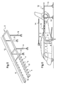
- Figure 1 shows an example of an embodiment of a lifting device 1 for replacing dynamic or static components of helicopter-type rotary wing aircraft, characterised in that it comprises a lifting means 2 to move said components between an installation/removal position on the aircraft and a loading/unloading position near the aircraft, for example on the ground.
- Figure 1 shows the lifting device 1 in a first installation configuration on a helicopter (not shown).
- the lifting device 1 comprises a supporting structure 3 on which the lifting means 2 is mounted,
- the lifting device 1 comprises support means 4 rigidly attached to the supporting structure 3 and designed to rest directly on an airframe 5 (not shown) of the aircraft.
- the supporting structure 3 comprises attachment or immobilisation means 6 having a shape that complements the shape of the airframe 5 (not shown), intended to partly encompass said airframe 5.
- the attachment or immobilisation means 6 are known as such.
- Additional attachment members 7 consisting of attachment rods connected to the supporting structure 3 are also provided for this purpose. These rods are secured for instance at fixed provisions of the helicopter or at the landing gear with a clamping belt or at other positions.
- the lifting device 1 also comprises handling means 8 to move the lifting means 2 from a position located near the aircraft to an operational position on the supporting structure 3, once the latter has been secured to the airframe 5.
- the handling means 8 may, for example, consist of installation rails.
- the lifting means 2 is preferably mounted in a movable manner on the supporting structure 3.
- the lifting means 2 is mounted rotationally movable on a trolley 9, which itself is translationally movable on the supporting structure 3.
- the trolley 9 is also used to move the lifting means 2 on the handling means 8, for example by means of a manually or motor-operated winch (not shown).
- the supporting structure 3 therefore comprises at least one part on which the lifting means 2 travels.
- the supporting structure 3 may, for example, comprise two parallel rails 10 resting on the airframe 5 in a substantially centred manner, via the support means 4.
- the support means 4 comprise pads capable of locally adapting to the outer shape of the airframe 5. These pads may, for example, comprise a flexible element or contact layer. The airframe 5 can so be protected.
- the pads may comprise attachment members cooperating with external predefined parts of said airframe 5.
- the pads are preferably distributed on the supporting structure 3 in such a manner that when said supporting structure 3 is mounted on the airframe 5, their positions correspond to reinforced regions of said airframe 5.
- the supporting structure 3 shown in figure 3 comprises a first part 11 equipped with support means 4 and a second part 12 equipped with ground-based support members 13.
- the second part 12 extends longitudinally from the first part 11 along a longitudinal direction of the helicopter.
- the trolley 9 can thus travel on each of parts 11 and 12 of the supporting structure 3.
- the latter is positioned at the forward end of the airframe 5 of the helicopter.
- Figure 4 shows the supporting structure 3 of figure 3 once mounted on the airframe 5 of a helicopter, below the extension plane of the rotor blades 14.
- the supporting structure 3 shown in figure 5 is intended to be positioned at the aft end of the airframe 5 of a helicopter.
- Figure 6 can be referred to, for example.
- the supporting structures 3 shown in figures 3 and 5 may constitute identical or different modules. In certain cases, it is possible to differentiate the first parts 11 from the supporting structures 3 so as to ensure good adaptability to the airframe 5. This is indispensable when the outer shape of the airframe 5 in the regions where the pads rest is different at the forward and aft ends.
- the ground-based support members 13 are preferably adjustable lengthwise to adapt to ground irregularities. All known length adjustment systems, such as screw jacks, adjusting screws or others, may be integrated into the ground-based support members 13.
- the lifting device may, for example, be associated with airframe reinforcement means 15 arranged inside said airframe 5.
- the reinforcement means 15 shown in figure 7 or 9 comprise adjustable length beams positioned in a substantially vertical position inside the airframe 5 and resting at one end on the floor 5a of said airframe 5 and at the other end against the roof of the airframe 5 via a crossbar 16. The latter allows better distribution of the stresses generated by the lifting device.
- the reinforcement means 15 may extend substantially along the diagonal directions of the airframe 5.
- the number and position of the reinforcement means 15 are of course adapted to the load to be withstood by the airframe 5 and to the intrinsic structural reinforcements of said airframe 5. A specific adaptation for each type or model of helicopter is preferable.
- the lifting means 2 may, for example, consist of an articulated and/or telescopic arm.
- the lifting means known as such, may comprise one or more articulated sections.
- the lifting device also comprises hydraulic and/or electrical control means to move the lifting arm and the trolley 9.
- the trolley 9 is moved for instance with manpower or with other elements at a transport device or via tracks on stabilization means.
- a transportation device which includes elements to bring the lifting means in the working position and hydraulic and/or electrical control means.
- the lifting device comprises stabilisation means 17 designed to be secured to the supporting structure 3 and to rest on the ground.
- the stabilisation means 17 may, for example, consist of adjustable length rods arranged on both sides of the airframe 5, with the most distant end from the airframe 5 resting on the ground. This improves the stability of the assembly formed by the lifting device 1 and the helicopter.
- the handling means 8 may at least partly constitute the stabilisation means 17.
- Figures 1 and 2 can be referred to, for example.
- the lifting device 1 of the present invention shown in figure 9 and figure 10 comprises additional stabilisation means 18 rigidly attached to the rails 10 and resting on the ground.
- the additional stabilisation means 18 advantageously comprise two horizontal beams 19 extending transversely to the rails 10 and between which the trolley 9 is positioned.
- the additional stabilisation means 18 also comprise, on both sides of the airframe 5, two vertical beams 20 with adjustable lengths and resting on the ground.
- the additional stabilisation means 18 advantageously move with the trolley 9. This ensures optimal stability for each position of the lifting means 2 on the supporting structure 3.
- these beams 19, 20 are connected at fixed provisions of the helicopter or at the landing gear with a clamping belt or at other positions.
- the additional stabilisation means 18 may be used alone or in association with the stabilisation means 17 and/or the handling means 8.
- the lifting device is modular, with dimensions after disassembly allowing it to be transported as internal or external load on a helicopter.
- the supporting structure 3 comprises a first lateral part 21 equipped with support means 4 in contact with an upper lateral part of the airframe 5.
- the lifting means 2 is a winch or hoist type device mounted on a mobile structure 23. The latter moves translationally along a lateral direction on the second lateral part 22.
- the lifting means 2 is raised with respect to the second lateral part 22 and moves translationally along a longitudinal direction on the mobile structure 23.
- the lifting device 1 of the present invention can therefore easily lower an engine 24 onto the ground and load a new engine 24 to place it in its compartment on the airframe 5.
- a third design of the lifting device of the present invention would consist of associating the lifting device 1 according to the second design with a lifting device 1 according to the first design. Such a complex lifting device could be useful when repairing a helicopter of significant size and/or with specific structural characteristics.
Landscapes
- Engineering & Computer Science (AREA)
- Mechanical Engineering (AREA)
- Transportation (AREA)
- Civil Engineering (AREA)
- Structural Engineering (AREA)
- Manufacturing & Machinery (AREA)
- Aviation & Aerospace Engineering (AREA)
- Load-Engaging Elements For Cranes (AREA)
- Toys (AREA)
- Automatic Assembly (AREA)
Abstract
Description
- The present invention generally concerns the technical repair of rotary wing aircraft, particularly helicopters. Although specific reference will be made hereinafter to helicopters, the present invention is clearly applicable to all types of rotary wing aircraft.
- When a helicopter suffers a severe malfunction that prevents it from pursuing its mission, it may need to perform an emergency landing in an area that is difficult or impossible to access due to the nature of the terrain, such as a mountain area. The helicopter may suffer a mechanical or electrical engine malfunction and/or a deterioration of one of its structural components, damages on dynamic components (rotor blades, shafts, gearboxes etc...), causing it to remain immobilised without possibility of repair by crew members using on-board equipment.
- In addition, landing areas may be controlled by enemy forces and therefore inaccessible for land vehicles transporting the components needed to repair the helicopter or used to load and retrieve said helicopter. In war zones, the helicopter is therefore either abandoned or destroyed.
- The present invention aims to provide a new device that can be used to overcome the above-mentioned limitations and repair the helicopter on site.
- Another aim of the invention is to provide a new device suitable for the type of helicopter to be repaired.
- Another aim of the invention is to provide a new device suited for use in all types of terrain.
- The intended aims of the present invention are achieved by means of a lifting device for replacing dynamic or static components of helicopter-type rotary wing aircraft, characterised in that it comprises the following:
- a lifting means to move said components between an installation/removal position and a loading/unloading position located near the aircraft,
- a supporting structure on which the lifting means is mounted,
- support means rigidly attached to the supporting structure, designed to rest on and/or be directly secured to an airframe of the aircraft,
- and immobilisation or attachment means to secure the supporting structure to the airframe.
- According to an example of an embodiment of the lifting device of the present invention, the lifting means is mounted in a movable manner on the supporting structure. This facilitates access to the various dynamic or static components to be removed from the helicopter.
- According to an example of an embodiment of the present invention, the lifting device comprises handling means to move the lifting means from a position located near the aircraft to an operational position on the supporting structure, once the latter has been secured to the airframe. This facilitates the work of repair personnel, particularly in the absence of other means, such as a crane, to place the lifting means in an operational position.
- According to an example of an embodiment of the present invention, the lifting device comprises stabilisation means designed to be secured to the supporting structure and to rest on the ground. The stabilisation means are subsequently also used to stabilize the aircraft.
- According to another example of an embodiment of the present invention, the handling means at least partly constitute the stabilisation means.
- According to an example of an embodiment of the present invention, the support means comprise pads capable of locally adapting to the outer shape of the airframe and resting directly on said airframe. In this manner, the helicopter is used as a means to stabilise the lifting device. The number of stabilisation components required can therefore be reduced.
- According to an example of an embodiment of the present invention, the pads are distributed on the supporting structure in such a manner that when said supporting structure is mounted on the airframe, their positions correspond to reinforced regions of said airframe. This prevents risks of airframe deformation.
- According to an example of an embodiment of the present invention, the supporting structure comprises at least one part on which the lifting means travels. The latter can thus position itself in an optimal manner with respect to the components to be replaced.
- According to an example of an embodiment of the present invention, the supporting structure comprises a first part equipped with support means and a second part equipped with ground-based support members, extending longitudinally from the first part.
- According to an example of an embodiment of the present invention, the first part of the supporting structure comprises two parallel rails resting on the airframe in a substantially centred manner, via the support means.
- Therefore, in case of unstable terrain, the helicopter alone can ensure the stability of the lifting device.
- According to an example of an embodiment of the present invention, the lifting means is an articulated and/or telescopic arm.
- The lifting means may, for example, be mounted rotationally movable on a trolley, which itself is translationally movable on the supporting structure.
- According to an example of an embodiment of the present invention, the lifting device is associated with airframe reinforcement means arranged inside said airframe. This prevents the risk of airframe deformation due to the significant weight of the lifting means when lifting a component such as an engine.
- According to an example of an embodiment of the present invention, the supporting structure comprises a first lateral part equipped with support means in contact with an upper lateral part of the airframe, and a second lateral part extending from the first lateral part, said second lateral part being equipped with ground-based support members.
- Therefore, in case of unstable terrain, the helicopter alone can significantly contribute to ensuring the stability of the lifting device. Such an example of an embodiment is suited for replacing the lateral components of the helicopter as well as other components.
- According to such an example of an embodiment of the present invention, the lifting means is a winch or hoist type device mounted on a mobile structure moving at least translationally in at least one direction on the first and second lateral parts.
- According to an example of an embodiment of the present invention, the lifting device comprises hydraulic and/or electrical control means. These control means are advantageously powered by the helicopter itself or by a specific power source that is part of the lifting device.
- According to an example of an embodiment of the present invention, the lifting device is modular, with dimensions after disassembly allowing it to be transported as internal or external load on a helicopter. In certain situations, the possibility of integrating the lifting device with the helicopter's on-board equipment can also be considered.
- The lifting device of the present invention provides the advantage of being compact and adaptable to all types of terrain.
- Another advantage of the lifting device of the present invention is its modular design, allowing easy assembly and disassembly.
- Another advantage of the lifting device of the present invention is that it can be used to replace all dynamic or static components of the helicopter, even large or heavy components, thus allowing said helicopter to pursue its mission or return to its base once the replacement of the defective components has been completed.
- Another advantage of the lifting device of the present invention is that it is independent on the infrastructure.
- Another advantage of the lifting device of the present invention is it can be used to replace/change all necessary components of the aircraft or helicopter.
- Another advantage of the lifting device of the present invention is that it can be carried by internal or external cargo (load).
- Another advantage of the lifting device of the present invention is that it contributes to stabilize the helicopter or aircraft.
- Another advantage of the lifting device of the present invention is that it reduces risks. The helicopter can land instead of flying with a damage, since a maintenance operation can take place.
- The characteristics and advantages of the present invention will become more apparent from the description that follows of illustrative, non-exhaustive examples of embodiments, given with reference to the attached figures, where:
-
figure 1 is a schematic perspective view of an example of an embodiment of the lifting device of the present invention, in a first configuration, -
figure 2 is a schematic perspective view of an example of an embodiment of the lifting device of the present invention, in a second configuration, -
figure 3 is a schematic perspective view of part of another example of an embodiment of the lifting device of the present invention, in a third configuration, -
figure 4 is a schematic profile view of the part of the device of the present invention shown infigure 3 , mounted on a helicopter, -
figure 5 is a schematic perspective view of part of another example of an embodiment of the lifting device of the present invention, in a fourth configuration, -
figure 6 is a schematic profile view of the part of the device of the present invention shown infigure 5 , mounted on a helicopter, -
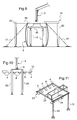
figure 7 is a cross-sectional front view of a helicopter airframe on which the lifting device of the present invention has been mounted, associated with stabilisation means and airframe reinforcement means, in a first configuration, -
figure 8 is a cross-sectional front view of a helicopter airframe on which the lifting device of the present invention has been mounted, associated with stabilisation means and airframe reinforcement means, in a second configuration, -
figure 9 is a cross-sectional front view of a helicopter airframe on which the lifting device of the present invention has been mounted, associated with additional stabilisation means and airframe reinforcement means, in a first configuration, -
figure 10 is a partial schematic view, along direction A infigure 9 , of the additional stabilisation means associated with lifting device of the present invention, -
figure 11 is a schematic perspective view of another example of an embodiment of the lifting device of the present invention, -
figure 12 is a schematic front view of the part of the lifting device shown infigure 11 , mounted laterally on the airframe of a helicopter, - and
figure 13 is an enlarged and simplified view offigure 12 . - Structurally and functionally identical components appearing in different figures are assigned the same numerical or alphanumerical reference.
- In addition, structural and/or functional characteristics described for a given embodiment of the lifting device of the present invention may be present in another embodiment without necessarily being described again.
- A first design of the lifting device of the present invention is shown in
figures 1 to 10 . -
Figure 1 shows an example of an embodiment of a lifting device 1 for replacing dynamic or static components of helicopter-type rotary wing aircraft, characterised in that it comprises a lifting means 2 to move said components between an installation/removal position on the aircraft and a loading/unloading position near the aircraft, for example on the ground.Figure 1 shows the lifting device 1 in a first installation configuration on a helicopter (not shown). - The lifting device 1 comprises a supporting
structure 3 on which the lifting means 2 is mounted, - The lifting device 1 comprises support means 4 rigidly attached to the supporting
structure 3 and designed to rest directly on an airframe 5 (not shown) of the aircraft. - For this purpose, the supporting
structure 3 comprises attachment or immobilisation means 6 having a shape that complements the shape of the airframe 5 (not shown), intended to partly encompass saidairframe 5. The attachment or immobilisation means 6 are known as such. -
Additional attachment members 7 consisting of attachment rods connected to the supportingstructure 3 are also provided for this purpose. These rods are secured for instance at fixed provisions of the helicopter or at the landing gear with a clamping belt or at other positions. - The lifting device 1 also comprises handling means 8 to move the lifting means 2 from a position located near the aircraft to an operational position on the supporting
structure 3, once the latter has been secured to theairframe 5. The handling means 8 may, for example, consist of installation rails. - The lifting means 2 is preferably mounted in a movable manner on the supporting
structure 3. For example, in an operational configuration shown infigure 2 , the lifting means 2 is mounted rotationally movable on atrolley 9, which itself is translationally movable on the supportingstructure 3. Thetrolley 9 is also used to move the lifting means 2 on the handling means 8, for example by means of a manually or motor-operated winch (not shown). - The supporting
structure 3 therefore comprises at least one part on which the lifting means 2 travels. The supportingstructure 3 may, for example, comprise twoparallel rails 10 resting on theairframe 5 in a substantially centred manner, via the support means 4. - The support means 4 comprise pads capable of locally adapting to the outer shape of the
airframe 5. These pads may, for example, comprise a flexible element or contact layer. Theairframe 5 can so be protected. - Advantageously, the pads may comprise attachment members cooperating with external predefined parts of said
airframe 5. - The pads are preferably distributed on the supporting
structure 3 in such a manner that when said supportingstructure 3 is mounted on theairframe 5, their positions correspond to reinforced regions of saidairframe 5. - The supporting
structure 3 shown infigure 3 comprises afirst part 11 equipped with support means 4 and asecond part 12 equipped with ground-basedsupport members 13. Thesecond part 12 extends longitudinally from thefirst part 11 along a longitudinal direction of the helicopter. Thetrolley 9 can thus travel on each ofparts structure 3. The latter is positioned at the forward end of theairframe 5 of the helicopter. -
Figure 4 shows the supportingstructure 3 offigure 3 once mounted on theairframe 5 of a helicopter, below the extension plane of therotor blades 14. - The supporting
structure 3 shown infigure 5 is intended to be positioned at the aft end of theairframe 5 of a helicopter.Figure 6 can be referred to, for example. The supportingstructures 3 shown infigures 3 and5 may constitute identical or different modules. In certain cases, it is possible to differentiate thefirst parts 11 from the supportingstructures 3 so as to ensure good adaptability to theairframe 5. This is indispensable when the outer shape of theairframe 5 in the regions where the pads rest is different at the forward and aft ends. - The ground-based
support members 13 are preferably adjustable lengthwise to adapt to ground irregularities. All known length adjustment systems, such as screw jacks, adjusting screws or others, may be integrated into the ground-basedsupport members 13. - The lifting device may, for example, be associated with airframe reinforcement means 15 arranged inside said
airframe 5. - The reinforcement means 15 shown in
figure 7 or9 comprise adjustable length beams positioned in a substantially vertical position inside theairframe 5 and resting at one end on the floor 5a of saidairframe 5 and at the other end against the roof of theairframe 5 via acrossbar 16. The latter allows better distribution of the stresses generated by the lifting device. - According to another installation method shown in
figure 8 , the reinforcement means 15 may extend substantially along the diagonal directions of theairframe 5. - The number and position of the reinforcement means 15 are of course adapted to the load to be withstood by the
airframe 5 and to the intrinsic structural reinforcements of saidairframe 5. A specific adaptation for each type or model of helicopter is preferable. - The lifting means 2 may, for example, consist of an articulated and/or telescopic arm. The lifting means, known as such, may comprise one or more articulated sections.
- The lifting device also comprises hydraulic and/or electrical control means to move the lifting arm and the
trolley 9. Thetrolley 9 is moved for instance with manpower or with other elements at a transport device or via tracks on stabilization means. - In another possibility, a transportation device can be used which includes elements to bring the lifting means in the working position and hydraulic and/or electrical control means.
- According to an example of an embodiment, the lifting device comprises stabilisation means 17 designed to be secured to the supporting
structure 3 and to rest on the ground. The stabilisation means 17 may, for example, consist of adjustable length rods arranged on both sides of theairframe 5, with the most distant end from theairframe 5 resting on the ground. This improves the stability of the assembly formed by the lifting device 1 and the helicopter. - According to another example of an embodiment of the lifting device 1, the handling means 8 may at least partly constitute the stabilisation means 17.
Figures 1 and 2 can be referred to, for example. - The lifting device 1 of the present invention shown in
figure 9 and figure 10 comprises additional stabilisation means 18 rigidly attached to therails 10 and resting on the ground. The additional stabilisation means 18 advantageously comprise twohorizontal beams 19 extending transversely to therails 10 and between which thetrolley 9 is positioned. The additional stabilisation means 18 also comprise, on both sides of theairframe 5, twovertical beams 20 with adjustable lengths and resting on the ground. - The additional stabilisation means 18 advantageously move with the
trolley 9. This ensures optimal stability for each position of the lifting means 2 on the supportingstructure 3. By way of examples, thesebeams - The additional stabilisation means 18 may be used alone or in association with the stabilisation means 17 and/or the handling means 8.
- According to an example of an embodiment of the present invention, the lifting device is modular, with dimensions after disassembly allowing it to be transported as internal or external load on a helicopter.
- According to a second modular design of the lifting device of the present invention, shown in
figures 11 to 13 , the supportingstructure 3 comprises a firstlateral part 21 equipped with support means 4 in contact with an upper lateral part of theairframe 5. - A second
lateral part 22, consisting for example of parallel rails extending laterally from the firstlateral part 21, is equipped with ground-basedsupport members 13. - The lifting means 2 is a winch or hoist type device mounted on a
mobile structure 23. The latter moves translationally along a lateral direction on the secondlateral part 22. - The lifting means 2 is raised with respect to the second
lateral part 22 and moves translationally along a longitudinal direction on themobile structure 23. - The lifting device 1 of the present invention can therefore easily lower an
engine 24 onto the ground and load anew engine 24 to place it in its compartment on theairframe 5. - A third design of the lifting device of the present invention would consist of associating the lifting device 1 according to the second design with a lifting device 1 according to the first design. Such a complex lifting device could be useful when repairing a helicopter of significant size and/or with specific structural characteristics.
- Naturally, the present invention is subject to numerous variations as to its implementation. Although several embodiments have been described, it is obviously not possible to exhaustively identify all possible embodiments. The possibility of replacing one of the means described with an equivalent means can of course be considered without departing from the scope of the present invention.
Claims (17)
- Lifting device (1) for replacing dynamic or static components of helicopter-type rotary wing aircraft,
characterised in that it comprises the following:- a lifting means (2) to move said components between an installation/removal position and a loading/unloading position located near the aircraft,- a supporting structure (3) on which the lifting means (2) is mounted,- support means (4) rigidly attached to the supporting structure, designed to rest on and/or be directly secured to an airframe (5) of the aircraft,- and immobilisation or attachment means (6,7) to secure the supporting structure (3) to the airframe (5). - Lifting device (1) according to claim 1,
characterised in that the lifting means (2) is mounted in a movable manner on the supporting structure (3). - Lifting device (1) according to claim 1 or 2,
characterised in that it comprises handling means (8) to move the lifting means (2) from a position located near the aircraft to an operational position on the supporting structure (3), once the latter has been secured to the airframe (5). - Lifting device (1) according to any of the previous claims,
characterised in that it comprises stabilisation means (17,18) designed to be secured to the supporting structure (3) and to rest on the ground. - Lifting device (1) according to claims 3 and 4,
characterised in that the handling means (8) at least partly constitute the stabilisation means (17). - Lifting device (1) according to any of the previous claims,
characterised in that the support means (4) comprise pads capable of locally adapting to the outer shape of the airframe (5) and resting directly on said airframe (5). - Lifting device (1) according to claim 6,
characterised in that the pads are distributed on the supporting structure (3) in such a manner that when said supporting structure (3) is mounted on the airframe (5), their positions correspond to reinforced regions of said airframe (5). - Lifting device (1) according to claim 7,
characterised in that the supporting structure (3) comprises at least one part on which the lifting means (2) travels. - Lifting device (1) according to any of claims 1 to 8,
characterised in that the supporting structure (3) comprises a first part (11) equipped with support means (4) and a second part (12) equipped with ground-based support members (13), extending longitudinally from the first part (11). - Lifting device (1) according to claim 9,
characterised in that the first part (11) of the supporting structure (3) comprises two parallel rails (10) resting on the airframe (5) in a substantially centred manner, via the support means (4). - Lifting device (1) according to claim 9 or 10,
characterised in that the lifting means (2) is an articulated and/or telescopic arm. - Lifting device (1) according to claim 11,
characterised in that the lifting means (2) is mounted rotationally movable on a trolley (9), which is translationally movable on the supporting structure (3). - Lifting device (1) according to any of claims 9 to 12,
characterised in that it is associated with airframe reinforcement means (15) arranged inside said airframe (5). - Lifting device (1) according to any of claims 1 to 8,
characterised in that the supporting structure (3) comprises a first lateral part (21) equipped with support means (4) in contact with an upper lateral part of the airframe (5), and a second lateral part (22) extending from the first lateral part (21), said second lateral part (22) being equipped with ground-based support members (13). - Lifting device (1) according to claim 14,
characterised in that the lifting means (2) is a winch or hoist type device mounted on a mobile structure (23) moving translationally in at least one direction on the first and second lateral parts (21,22). - Lifting device (1) according to any of claims 1 to 15,
characterised in that it comprises hydraulic and/or electrical control means. - Lifting device (1) according to any of claims 1 to 16,
characterised in that it is modular, with dimensions after disassembly allowing it to be transported as internal or external load on a helicopter.
Priority Applications (4)
| Application Number | Priority Date | Filing Date | Title |
|---|---|---|---|
| EP09400062.7A EP2338794B1 (en) | 2009-12-22 | 2009-12-22 | Lift device for replacing dynamic or static components of helicopter-type aircraft |
| US12/899,790 US8695817B2 (en) | 2009-12-22 | 2010-10-07 | Lifting device for replacing dynamic or static components of helicopter-type aircraft |
| KR1020100103449A KR101321827B1 (en) | 2009-12-22 | 2010-10-22 | Lifting device for replacing dynamic or static components of helicopter-type aircraft |
| CN201010554062.9A CN102101531B (en) | 2009-12-22 | 2010-11-11 | Lift device for replacing dynamic or static components of helicopter-type aircraft |
Applications Claiming Priority (1)
| Application Number | Priority Date | Filing Date | Title |
|---|---|---|---|
| EP09400062.7A EP2338794B1 (en) | 2009-12-22 | 2009-12-22 | Lift device for replacing dynamic or static components of helicopter-type aircraft |
Publications (2)
| Publication Number | Publication Date |
|---|---|
| EP2338794A1 true EP2338794A1 (en) | 2011-06-29 |
| EP2338794B1 EP2338794B1 (en) | 2018-08-29 |
Family
ID=42124341
Family Applications (1)
| Application Number | Title | Priority Date | Filing Date |
|---|---|---|---|
| EP09400062.7A Not-in-force EP2338794B1 (en) | 2009-12-22 | 2009-12-22 | Lift device for replacing dynamic or static components of helicopter-type aircraft |
Country Status (4)
| Country | Link |
|---|---|
| US (1) | US8695817B2 (en) |
| EP (1) | EP2338794B1 (en) |
| KR (1) | KR101321827B1 (en) |
| CN (1) | CN102101531B (en) |
Cited By (4)
| Publication number | Priority date | Publication date | Assignee | Title |
|---|---|---|---|---|
| RU2611446C1 (en) * | 2015-12-09 | 2017-02-22 | Акционерное общество "Московский вертолетный завод им. М.Л. Миля" | Stand for helicopter ground tests |
| CN107922057A (en) * | 2015-07-16 | 2018-04-17 | 吉诺公司 | Intelligent aircraft floor supporter |
| DE102020116443A1 (en) | 2020-06-22 | 2021-12-23 | Airbus Defence and Space GmbH | Transport system for transporting a load device, method for controlling a transport system and aircraft with a transport system |
| DE102020116442A1 (en) | 2020-06-22 | 2021-12-23 | Airbus Defence and Space GmbH | Fastening device for releasably fastening a load device to a guide device, transport system and aircraft with a fastening device |
Families Citing this family (8)
| Publication number | Priority date | Publication date | Assignee | Title |
|---|---|---|---|---|
| CN103407579B (en) * | 2012-12-10 | 2016-03-30 | 中国飞机强度研究所 | A kind of major diameter airframe test loads fixture |
| FR3014838B1 (en) * | 2013-12-17 | 2015-12-25 | Eurocopter France | GIRAVION EQUIPPED WITH A REVERSE ROTOR ANTI COUPLE PARTICIPATING SELECTIVELY TO THE SUSTENTATION AND PROPULSION IN TRANSLATION OF THE GIRAVION |
| CN103991649B (en) * | 2014-06-12 | 2016-04-20 | 沈阳飞机工业(集团)有限公司 | The collapsible pallet for transporting of large-scale main body section section |
| US10982805B2 (en) * | 2015-03-23 | 2021-04-20 | Lockheed Martin Corporation | Ergonomic device for suspending aircraft flight control apparatuses |
| CN107628252A (en) * | 2017-09-11 | 2018-01-26 | 中国航空工业集团公司西安飞机设计研究所 | A kind of aviation goods handler |
| CN108910679A (en) * | 2018-07-06 | 2018-11-30 | 西安爱生技术集团公司 | A kind of unmanned plane flexible hanger |
| US11443640B2 (en) | 2018-10-19 | 2022-09-13 | Anduril Industries, Inc. | Ruggedized autonomous helicopter platform |
| KR102517049B1 (en) * | 2021-04-08 | 2023-04-04 | 한국항공우주산업 주식회사 | Lifting apparatus of assembly parts for aircraft |
Citations (5)
| Publication number | Priority date | Publication date | Assignee | Title |
|---|---|---|---|---|
| GB273912A (en) * | 1926-07-24 | 1927-07-14 | Blackburn Aeroplane & Motor Co | Improvements in or connected with means for changing or installing engines on aircraft |
| GB863085A (en) * | 1956-10-17 | 1961-03-15 | Sud Aviation | Improvements in or relating to outfits for emplaning and servicing light helicopters |
| US3071349A (en) * | 1958-12-12 | 1963-01-01 | Herbert L Glaze | Hoist |
| US3380688A (en) * | 1966-10-13 | 1968-04-30 | Roger S. Adams | Helicopter hoist |
| WO1993006008A1 (en) * | 1991-09-17 | 1993-04-01 | Rolls-Royce Plc | Method of and apparatus for removing and replacing a part or parts of a gas turbine engine powerplant |
Family Cites Families (3)
| Publication number | Priority date | Publication date | Assignee | Title |
|---|---|---|---|---|
| US3845937A (en) * | 1973-12-14 | 1974-11-05 | Us Navy | Helicopter cargo lifting system |
| KR200178117Y1 (en) * | 1996-01-31 | 2000-06-01 | 유무성 | Lifting device for airplane wing assembly |
| DE10201202B4 (en) | 2002-01-14 | 2009-11-26 | Otmar Fahrion | Docking unit for servicing an aircraft or the like |
-
2009
- 2009-12-22 EP EP09400062.7A patent/EP2338794B1/en not_active Not-in-force
-
2010
- 2010-10-07 US US12/899,790 patent/US8695817B2/en not_active Expired - Fee Related
- 2010-10-22 KR KR1020100103449A patent/KR101321827B1/en not_active Expired - Fee Related
- 2010-11-11 CN CN201010554062.9A patent/CN102101531B/en not_active Expired - Fee Related
Patent Citations (5)
| Publication number | Priority date | Publication date | Assignee | Title |
|---|---|---|---|---|
| GB273912A (en) * | 1926-07-24 | 1927-07-14 | Blackburn Aeroplane & Motor Co | Improvements in or connected with means for changing or installing engines on aircraft |
| GB863085A (en) * | 1956-10-17 | 1961-03-15 | Sud Aviation | Improvements in or relating to outfits for emplaning and servicing light helicopters |
| US3071349A (en) * | 1958-12-12 | 1963-01-01 | Herbert L Glaze | Hoist |
| US3380688A (en) * | 1966-10-13 | 1968-04-30 | Roger S. Adams | Helicopter hoist |
| WO1993006008A1 (en) * | 1991-09-17 | 1993-04-01 | Rolls-Royce Plc | Method of and apparatus for removing and replacing a part or parts of a gas turbine engine powerplant |
Cited By (8)
| Publication number | Priority date | Publication date | Assignee | Title |
|---|---|---|---|---|
| CN107922057A (en) * | 2015-07-16 | 2018-04-17 | 吉诺公司 | Intelligent aircraft floor supporter |
| RU2611446C1 (en) * | 2015-12-09 | 2017-02-22 | Акционерное общество "Московский вертолетный завод им. М.Л. Миля" | Stand for helicopter ground tests |
| DE102020116443A1 (en) | 2020-06-22 | 2021-12-23 | Airbus Defence and Space GmbH | Transport system for transporting a load device, method for controlling a transport system and aircraft with a transport system |
| DE102020116442A1 (en) | 2020-06-22 | 2021-12-23 | Airbus Defence and Space GmbH | Fastening device for releasably fastening a load device to a guide device, transport system and aircraft with a fastening device |
| EP3929082A1 (en) | 2020-06-22 | 2021-12-29 | Airbus Defence and Space GmbH | Fastening device for detachably fixing a load device to a guiding device, transport system and aircraft with a fixing device |
| EP3929139A1 (en) | 2020-06-22 | 2021-12-29 | Airbus Defence and Space GmbH | Transport system for transporting a load device, method for controlling a transport system and aircraft with a transport system |
| DE102020116443B4 (en) | 2020-06-22 | 2022-08-11 | Airbus Defence and Space GmbH | Transport system for transporting a load device, method for controlling a transport system and aircraft with a transport system |
| DE102020116442B4 (en) * | 2020-06-22 | 2025-08-07 | Airbus Defence and Space GmbH | Fastening device for releasably fastening a load device to a guide device, transport system and aircraft with a fastening device |
Also Published As
| Publication number | Publication date |
|---|---|
| US20110147328A1 (en) | 2011-06-23 |
| CN102101531B (en) | 2014-10-08 |
| EP2338794B1 (en) | 2018-08-29 |
| KR20110073237A (en) | 2011-06-29 |
| US8695817B2 (en) | 2014-04-15 |
| CN102101531A (en) | 2011-06-22 |
| KR101321827B1 (en) | 2013-10-29 |
Similar Documents
| Publication | Publication Date | Title |
|---|---|---|
| US8695817B2 (en) | Lifting device for replacing dynamic or static components of helicopter-type aircraft | |
| US5575607A (en) | Jet engine transport vehicle lift system and a build cell | |
| US8465247B2 (en) | Aircraft landing gear loader | |
| US7604134B2 (en) | Portable knockdown trolley hoist | |
| US9663228B2 (en) | Automated sling load handler for an aircraft | |
| CN101479470B (en) | Steering systems for wind turbine nacelles, methods of transport and vertical displacement, and applications of the maneuvering systems | |
| US6292999B1 (en) | Method of installing and removing jet aircraft engine | |
| US7103952B2 (en) | Engine loader and transporter apparatus and methods | |
| US11713139B2 (en) | Movable carriage system and method for implementing a movable carriage system | |
| DE102019101310B4 (en) | Dock leveler and method for reloading a load between two spaced depots | |
| CN110167868B (en) | Mobile base for a transfer device and method for transferring a device | |
| EP1785350B1 (en) | Apparatus for manipulating heavy loads | |
| CN104121144A (en) | Assembly method of wind power generation system | |
| ES2258587T3 (en) | PROCEDURE FOR LOADING AND UNLOADING AN AIRPLANE AS WELL AS MOBILE DEVICE FOR LOADING AN AIRPLANE | |
| US9260176B2 (en) | Retractable cargo roller system | |
| KR20190024953A (en) | Airborne forklifts and loading methods | |
| US20110146046A1 (en) | Method and apparatus for removing and replacing components of an airplane | |
| EP2165932A2 (en) | Transport and fitting vehicle for a component module | |
| WO2022191839A1 (en) | Removable cargo floor systems and methods for cargo aircraft | |
| US12280892B2 (en) | Cradle for an aircraft landing gear assembly | |
| JP4507913B2 (en) | Transporting and loading heavy objects | |
| KR102817485B1 (en) | Towing vehicle for taxiing various skid-type vtol aircraft | |
| EP4143124B1 (en) | A work machine with double-operator cabin and crane system | |
| CN114290343B (en) | Bridging robot | |
| CN113338091B (en) | Construction operation platform of high-speed magnetic levitation elevated section |
Legal Events
| Date | Code | Title | Description |
|---|---|---|---|
| PUAI | Public reference made under article 153(3) epc to a published international application that has entered the european phase |
Free format text: ORIGINAL CODE: 0009012 |
|
| AK | Designated contracting states |
Kind code of ref document: A1 Designated state(s): AT BE BG CH CY CZ DE DK EE ES FI FR GB GR HR HU IE IS IT LI LT LU LV MC MK MT NL NO PL PT RO SE SI SK SM TR |
|
| AX | Request for extension of the european patent |
Extension state: AL BA RS |
|
| 17P | Request for examination filed |
Effective date: 20110609 |
|
| RIC1 | Information provided on ipc code assigned before grant |
Ipc: B66C 1/10 20060101ALI20120305BHEP Ipc: B64F 5/00 20060101AFI20120305BHEP Ipc: B66C 5/02 20060101ALI20120305BHEP |
|
| 17Q | First examination report despatched |
Effective date: 20130528 |
|
| RAP1 | Party data changed (applicant data changed or rights of an application transferred) |
Owner name: AIRBUS HELICOPTERS DEUTSCHLAND GMBH |
|
| GRAP | Despatch of communication of intention to grant a patent |
Free format text: ORIGINAL CODE: EPIDOSNIGR1 |
|
| INTG | Intention to grant announced |
Effective date: 20180607 |
|
| GRAS | Grant fee paid |
Free format text: ORIGINAL CODE: EPIDOSNIGR3 |
|
| GRAA | (expected) grant |
Free format text: ORIGINAL CODE: 0009210 |
|
| AK | Designated contracting states |
Kind code of ref document: B1 Designated state(s): AT BE BG CH CY CZ DE DK EE ES FI FR GB GR HR HU IE IS IT LI LT LU LV MC MK MT NL NO PL PT RO SE SI SK SM TR |
|
| REG | Reference to a national code |
Ref country code: GB Ref legal event code: FG4D |
|
| REG | Reference to a national code |
Ref country code: CH Ref legal event code: EP |
|
| REG | Reference to a national code |
Ref country code: AT Ref legal event code: REF Ref document number: 1034836 Country of ref document: AT Kind code of ref document: T Effective date: 20180915 |
|
| REG | Reference to a national code |
Ref country code: IE Ref legal event code: FG4D |
|
| REG | Reference to a national code |
Ref country code: DE Ref legal event code: R096 Ref document number: 602009054139 Country of ref document: DE |
|
| REG | Reference to a national code |
Ref country code: NL Ref legal event code: MP Effective date: 20180829 |
|
| REG | Reference to a national code |
Ref country code: LT Ref legal event code: MG4D |
|
| PG25 | Lapsed in a contracting state [announced via postgrant information from national office to epo] |
Ref country code: NO Free format text: LAPSE BECAUSE OF FAILURE TO SUBMIT A TRANSLATION OF THE DESCRIPTION OR TO PAY THE FEE WITHIN THE PRESCRIBED TIME-LIMIT Effective date: 20181129 Ref country code: NL Free format text: LAPSE BECAUSE OF FAILURE TO SUBMIT A TRANSLATION OF THE DESCRIPTION OR TO PAY THE FEE WITHIN THE PRESCRIBED TIME-LIMIT Effective date: 20180829 Ref country code: BG Free format text: LAPSE BECAUSE OF FAILURE TO SUBMIT A TRANSLATION OF THE DESCRIPTION OR TO PAY THE FEE WITHIN THE PRESCRIBED TIME-LIMIT Effective date: 20181129 Ref country code: IS Free format text: LAPSE BECAUSE OF FAILURE TO SUBMIT A TRANSLATION OF THE DESCRIPTION OR TO PAY THE FEE WITHIN THE PRESCRIBED TIME-LIMIT Effective date: 20181229 Ref country code: GR Free format text: LAPSE BECAUSE OF FAILURE TO SUBMIT A TRANSLATION OF THE DESCRIPTION OR TO PAY THE FEE WITHIN THE PRESCRIBED TIME-LIMIT Effective date: 20181130 Ref country code: FI Free format text: LAPSE BECAUSE OF FAILURE TO SUBMIT A TRANSLATION OF THE DESCRIPTION OR TO PAY THE FEE WITHIN THE PRESCRIBED TIME-LIMIT Effective date: 20180829 Ref country code: LT Free format text: LAPSE BECAUSE OF FAILURE TO SUBMIT A TRANSLATION OF THE DESCRIPTION OR TO PAY THE FEE WITHIN THE PRESCRIBED TIME-LIMIT Effective date: 20180829 Ref country code: SE Free format text: LAPSE BECAUSE OF FAILURE TO SUBMIT A TRANSLATION OF THE DESCRIPTION OR TO PAY THE FEE WITHIN THE PRESCRIBED TIME-LIMIT Effective date: 20180829 |
|
| REG | Reference to a national code |
Ref country code: AT Ref legal event code: MK05 Ref document number: 1034836 Country of ref document: AT Kind code of ref document: T Effective date: 20180829 |
|
| PG25 | Lapsed in a contracting state [announced via postgrant information from national office to epo] |
Ref country code: ES Free format text: LAPSE BECAUSE OF FAILURE TO SUBMIT A TRANSLATION OF THE DESCRIPTION OR TO PAY THE FEE WITHIN THE PRESCRIBED TIME-LIMIT Effective date: 20180829 Ref country code: LV Free format text: LAPSE BECAUSE OF FAILURE TO SUBMIT A TRANSLATION OF THE DESCRIPTION OR TO PAY THE FEE WITHIN THE PRESCRIBED TIME-LIMIT Effective date: 20180829 Ref country code: HR Free format text: LAPSE BECAUSE OF FAILURE TO SUBMIT A TRANSLATION OF THE DESCRIPTION OR TO PAY THE FEE WITHIN THE PRESCRIBED TIME-LIMIT Effective date: 20180829 |
|
| PG25 | Lapsed in a contracting state [announced via postgrant information from national office to epo] |
Ref country code: PL Free format text: LAPSE BECAUSE OF FAILURE TO SUBMIT A TRANSLATION OF THE DESCRIPTION OR TO PAY THE FEE WITHIN THE PRESCRIBED TIME-LIMIT Effective date: 20180829 Ref country code: EE Free format text: LAPSE BECAUSE OF FAILURE TO SUBMIT A TRANSLATION OF THE DESCRIPTION OR TO PAY THE FEE WITHIN THE PRESCRIBED TIME-LIMIT Effective date: 20180829 Ref country code: AT Free format text: LAPSE BECAUSE OF FAILURE TO SUBMIT A TRANSLATION OF THE DESCRIPTION OR TO PAY THE FEE WITHIN THE PRESCRIBED TIME-LIMIT Effective date: 20180829 Ref country code: IT Free format text: LAPSE BECAUSE OF FAILURE TO SUBMIT A TRANSLATION OF THE DESCRIPTION OR TO PAY THE FEE WITHIN THE PRESCRIBED TIME-LIMIT Effective date: 20180829 Ref country code: CZ Free format text: LAPSE BECAUSE OF FAILURE TO SUBMIT A TRANSLATION OF THE DESCRIPTION OR TO PAY THE FEE WITHIN THE PRESCRIBED TIME-LIMIT Effective date: 20180829 Ref country code: RO Free format text: LAPSE BECAUSE OF FAILURE TO SUBMIT A TRANSLATION OF THE DESCRIPTION OR TO PAY THE FEE WITHIN THE PRESCRIBED TIME-LIMIT Effective date: 20180829 |
|
| PG25 | Lapsed in a contracting state [announced via postgrant information from national office to epo] |
Ref country code: SM Free format text: LAPSE BECAUSE OF FAILURE TO SUBMIT A TRANSLATION OF THE DESCRIPTION OR TO PAY THE FEE WITHIN THE PRESCRIBED TIME-LIMIT Effective date: 20180829 Ref country code: DK Free format text: LAPSE BECAUSE OF FAILURE TO SUBMIT A TRANSLATION OF THE DESCRIPTION OR TO PAY THE FEE WITHIN THE PRESCRIBED TIME-LIMIT Effective date: 20180829 Ref country code: SK Free format text: LAPSE BECAUSE OF FAILURE TO SUBMIT A TRANSLATION OF THE DESCRIPTION OR TO PAY THE FEE WITHIN THE PRESCRIBED TIME-LIMIT Effective date: 20180829 |
|
| REG | Reference to a national code |
Ref country code: DE Ref legal event code: R097 Ref document number: 602009054139 Country of ref document: DE |
|
| PLBE | No opposition filed within time limit |
Free format text: ORIGINAL CODE: 0009261 |
|
| STAA | Information on the status of an ep patent application or granted ep patent |
Free format text: STATUS: NO OPPOSITION FILED WITHIN TIME LIMIT |
|
| REG | Reference to a national code |
Ref country code: CH Ref legal event code: PL |
|
| 26N | No opposition filed |
Effective date: 20190531 |
|
| GBPC | Gb: european patent ceased through non-payment of renewal fee |
Effective date: 20181222 |
|
| PG25 | Lapsed in a contracting state [announced via postgrant information from national office to epo] |
Ref country code: MC Free format text: LAPSE BECAUSE OF FAILURE TO SUBMIT A TRANSLATION OF THE DESCRIPTION OR TO PAY THE FEE WITHIN THE PRESCRIBED TIME-LIMIT Effective date: 20180829 Ref country code: LU Free format text: LAPSE BECAUSE OF NON-PAYMENT OF DUE FEES Effective date: 20181222 Ref country code: SI Free format text: LAPSE BECAUSE OF FAILURE TO SUBMIT A TRANSLATION OF THE DESCRIPTION OR TO PAY THE FEE WITHIN THE PRESCRIBED TIME-LIMIT Effective date: 20180829 |
|
| REG | Reference to a national code |
Ref country code: IE Ref legal event code: MM4A |
|
| REG | Reference to a national code |
Ref country code: BE Ref legal event code: MM Effective date: 20181231 |
|
| PG25 | Lapsed in a contracting state [announced via postgrant information from national office to epo] |
Ref country code: FR Free format text: LAPSE BECAUSE OF NON-PAYMENT OF DUE FEES Effective date: 20181231 Ref country code: IE Free format text: LAPSE BECAUSE OF NON-PAYMENT OF DUE FEES Effective date: 20181222 |
|
| PG25 | Lapsed in a contracting state [announced via postgrant information from national office to epo] |
Ref country code: BE Free format text: LAPSE BECAUSE OF NON-PAYMENT OF DUE FEES Effective date: 20181231 |
|
| PG25 | Lapsed in a contracting state [announced via postgrant information from national office to epo] |
Ref country code: CH Free format text: LAPSE BECAUSE OF NON-PAYMENT OF DUE FEES Effective date: 20181231 Ref country code: LI Free format text: LAPSE BECAUSE OF NON-PAYMENT OF DUE FEES Effective date: 20181231 Ref country code: GB Free format text: LAPSE BECAUSE OF NON-PAYMENT OF DUE FEES Effective date: 20181222 |
|
| PG25 | Lapsed in a contracting state [announced via postgrant information from national office to epo] |
Ref country code: MT Free format text: LAPSE BECAUSE OF NON-PAYMENT OF DUE FEES Effective date: 20181222 |
|
| PG25 | Lapsed in a contracting state [announced via postgrant information from national office to epo] |
Ref country code: TR Free format text: LAPSE BECAUSE OF FAILURE TO SUBMIT A TRANSLATION OF THE DESCRIPTION OR TO PAY THE FEE WITHIN THE PRESCRIBED TIME-LIMIT Effective date: 20180829 |
|
| PG25 | Lapsed in a contracting state [announced via postgrant information from national office to epo] |
Ref country code: PT Free format text: LAPSE BECAUSE OF FAILURE TO SUBMIT A TRANSLATION OF THE DESCRIPTION OR TO PAY THE FEE WITHIN THE PRESCRIBED TIME-LIMIT Effective date: 20180829 |
|
| PG25 | Lapsed in a contracting state [announced via postgrant information from national office to epo] |
Ref country code: CY Free format text: LAPSE BECAUSE OF FAILURE TO SUBMIT A TRANSLATION OF THE DESCRIPTION OR TO PAY THE FEE WITHIN THE PRESCRIBED TIME-LIMIT Effective date: 20180829 Ref country code: MK Free format text: LAPSE BECAUSE OF NON-PAYMENT OF DUE FEES Effective date: 20180829 Ref country code: HU Free format text: LAPSE BECAUSE OF FAILURE TO SUBMIT A TRANSLATION OF THE DESCRIPTION OR TO PAY THE FEE WITHIN THE PRESCRIBED TIME-LIMIT; INVALID AB INITIO Effective date: 20091222 |
|
| PGFP | Annual fee paid to national office [announced via postgrant information from national office to epo] |
Ref country code: DE Payment date: 20211210 Year of fee payment: 13 |
|
| REG | Reference to a national code |
Ref country code: DE Ref legal event code: R119 Ref document number: 602009054139 Country of ref document: DE |
|
| PG25 | Lapsed in a contracting state [announced via postgrant information from national office to epo] |
Ref country code: DE Free format text: LAPSE BECAUSE OF NON-PAYMENT OF DUE FEES Effective date: 20230701 |