EP2338706A1 - Suspension unit for a front axle of an industrial or commercial vehicle with damper struts and a transverse leaf spring - Google Patents
Suspension unit for a front axle of an industrial or commercial vehicle with damper struts and a transverse leaf spring Download PDFInfo
- Publication number
- EP2338706A1 EP2338706A1 EP09425523A EP09425523A EP2338706A1 EP 2338706 A1 EP2338706 A1 EP 2338706A1 EP 09425523 A EP09425523 A EP 09425523A EP 09425523 A EP09425523 A EP 09425523A EP 2338706 A1 EP2338706 A1 EP 2338706A1
- Authority
- EP
- European Patent Office
- Prior art keywords
- suspension unit
- vehicle
- shock
- wheel hub
- absorbing means
- Prior art date
- Legal status (The legal status is an assumption and is not a legal conclusion. Google has not performed a legal analysis and makes no representation as to the accuracy of the status listed.)
- Ceased
Links
- 239000000725 suspension Substances 0.000 title claims abstract description 33
- 230000035939 shock Effects 0.000 claims abstract description 14
- 239000003381 stabilizer Substances 0.000 claims abstract description 4
- 230000008878 coupling Effects 0.000 claims abstract description 3
- 238000010168 coupling process Methods 0.000 claims abstract description 3
- 238000005859 coupling reaction Methods 0.000 claims abstract description 3
- 239000006096 absorbing agent Substances 0.000 description 8
- 238000010276 construction Methods 0.000 description 1
- 230000004048 modification Effects 0.000 description 1
- 238000012986 modification Methods 0.000 description 1
- 230000010355 oscillation Effects 0.000 description 1
Images


Classifications
-
- B—PERFORMING OPERATIONS; TRANSPORTING
- B60—VEHICLES IN GENERAL
- B60G—VEHICLE SUSPENSION ARRANGEMENTS
- B60G3/00—Resilient suspensions for a single wheel
- B60G3/02—Resilient suspensions for a single wheel with a single pivoted arm
- B60G3/04—Resilient suspensions for a single wheel with a single pivoted arm the arm being essentially transverse to the longitudinal axis of the vehicle
- B60G3/06—Resilient suspensions for a single wheel with a single pivoted arm the arm being essentially transverse to the longitudinal axis of the vehicle the arm being rigid
-
- B—PERFORMING OPERATIONS; TRANSPORTING
- B60—VEHICLES IN GENERAL
- B60G—VEHICLE SUSPENSION ARRANGEMENTS
- B60G11/00—Resilient suspensions characterised by arrangement, location or kind of springs
- B60G11/02—Resilient suspensions characterised by arrangement, location or kind of springs having leaf springs only
- B60G11/08—Resilient suspensions characterised by arrangement, location or kind of springs having leaf springs only arranged substantially transverse to the longitudinal axis of the vehicle
-
- B—PERFORMING OPERATIONS; TRANSPORTING
- B60—VEHICLES IN GENERAL
- B60G—VEHICLE SUSPENSION ARRANGEMENTS
- B60G13/00—Resilient suspensions characterised by arrangement, location or type of vibration dampers
- B60G13/001—Arrangements for attachment of dampers
- B60G13/005—Arrangements for attachment of dampers characterised by the mounting on the axle or suspension arm of the damper unit
- B60G13/006—Arrangements for attachment of dampers characterised by the mounting on the axle or suspension arm of the damper unit on the stub axle
-
- B—PERFORMING OPERATIONS; TRANSPORTING
- B60—VEHICLES IN GENERAL
- B60G—VEHICLE SUSPENSION ARRANGEMENTS
- B60G2200/00—Indexing codes relating to suspension types
- B60G2200/10—Independent suspensions
- B60G2200/17—Independent suspensions with a strut contributing to the suspension geometry by being articulated onto the wheel support
-
- B—PERFORMING OPERATIONS; TRANSPORTING
- B60—VEHICLES IN GENERAL
- B60G—VEHICLE SUSPENSION ARRANGEMENTS
- B60G2200/00—Indexing codes relating to suspension types
- B60G2200/40—Indexing codes relating to the wheels in the suspensions
- B60G2200/42—Driven wheels or dead axles
-
- B—PERFORMING OPERATIONS; TRANSPORTING
- B60—VEHICLES IN GENERAL
- B60G—VEHICLE SUSPENSION ARRANGEMENTS
- B60G2200/00—Indexing codes relating to suspension types
- B60G2200/40—Indexing codes relating to the wheels in the suspensions
- B60G2200/44—Indexing codes relating to the wheels in the suspensions steerable
-
- B—PERFORMING OPERATIONS; TRANSPORTING
- B60—VEHICLES IN GENERAL
- B60G—VEHICLE SUSPENSION ARRANGEMENTS
- B60G2202/00—Indexing codes relating to the type of spring, damper or actuator
- B60G2202/10—Type of spring
- B60G2202/11—Leaf spring
- B60G2202/114—Leaf spring transversally arranged
-
- B—PERFORMING OPERATIONS; TRANSPORTING
- B60—VEHICLES IN GENERAL
- B60G—VEHICLE SUSPENSION ARRANGEMENTS
- B60G2206/00—Indexing codes related to the manufacturing of suspensions: constructional features, the materials used, procedures or tools
- B60G2206/01—Constructional features of suspension elements, e.g. arms, dampers, springs
- B60G2206/10—Constructional features of arms
- B60G2206/124—Constructional features of arms the arm having triangular or Y-shape, e.g. wishbone
-
- B—PERFORMING OPERATIONS; TRANSPORTING
- B60—VEHICLES IN GENERAL
- B60G—VEHICLE SUSPENSION ARRANGEMENTS
- B60G2300/00—Indexing codes relating to the type of vehicle
- B60G2300/02—Trucks; Load vehicles
- B60G2300/024—Light trucks
Definitions
- the present invention relates to a suspension unit for a front axle of an industrial or commercial vehicle.
- the invention is advantageously used for the shock absorbing of at least the front wheels of a transport vehicle of the unitized body type or of the unitized frame type with rear-wheel drive, such as for example a truck or similar, used for the commercial or the industrial transport, in order to guarantee the optimal stability of the vehicle and a constant and high comfort for the driver of the vehicle itself.
- suspension units which are applied to each wheel by connecting the wheel hub to the vehicle frame, as it is widely known in the art.
- the most widely used suspension unit in particular for the shock absorbing of the front steering axle of a commercial and/or industrial transport vehicles, is of the McPherson type with springing system using coil springs, which is mounted on a shock absorber in order to absorb the oscillations of the vehicle's wheel on which it is applied.
- This type of suspension unit even though it is able to effectively absorb the ground irregularities and to guarantee a good vehicle stability, presents structural limitations especially connected to the high tensions on the coil spring; such structural limitations increase the dimensions of the suspension system, thus making it not compatible with commercial vehicles.
- the specific configuration of the mentioned suspension unit needs some external space, in the wheelhouse, suitable for housing each wheel and its respective bulky suspension unit, consequently reducing the space in the cabin of the vehicle over the front wheels, devoted to the driving parts, namely pedals and steering wheels.
- the aim of the present invention is therefore to overcome the drawbacks of the prior art described above.
- an aim of the present invention is to realize a suspension unit for the front steering wheels of a vehicle, in particular for the commercial and industrial transport, which is effective and compact, in order to make the inside cabin wider and more comfortable, and consequently to make the driving of the vehicle itself safer and easier.
- a front suspension unit for a commercial or industrial vehicle with rear-wheel drive of the unitized body (S) type or of the unitized frame type comprises, coupled to each wheel hub at least of the front steering wheels of said vehicle: shock-absorbing means whose upper end is fixed to a wheelhouse of said body; a lower arm, to which a lower part of said shock-absorbing means is fixed, said lower arm being hinged on one side to a frame structure, and on the other side to a lower pin of the wheel hub; a support and coupling element of said shock-absorbing means to said wheel hub, said element being suitable for oscillating together with said wheel hub; leaf spring means connected to said wheel hub and transversally extending with respect to the longitudinal axis of the vehicle.
- the subject of the present invention is in particular a suspension unit for a front steering axle of an industrial or commercial vehicle, as described more fully in the claims, which are an integral part of this description.
- G generally indicates a suspension unit suitable for being applied and act on each wheel hub MR of the two front wheels of a vehicle V, in particular a vehicle for the commercial and industrial transport, with rear-wheel drive and with the engine (known in the art and not shown in the attached figures) longitudinally placed and mounted on a unitized body S or on a unitized frame by means of support and fixing means known in the art.
- the front part of the bodywork comprises a frame structure T suitable for supporting the longitudinal engine, such structure T being formed by a pair of longitudinal members T1 and T2 connected to each other by a rear cross bar Bt and by a front cradle C substantially saddle-shaped and transversally extending with respect to the longitudinal axis of the vehicle V.
- the unit G comprises as associated to each wheel hub MR:
Landscapes
- Engineering & Computer Science (AREA)
- Mechanical Engineering (AREA)
- Vehicle Body Suspensions (AREA)
Abstract
Description
- The present invention relates to a suspension unit for a front axle of an industrial or commercial vehicle.
- In particular, the invention is advantageously used for the shock absorbing of at least the front wheels of a transport vehicle of the unitized body type or of the unitized frame type with rear-wheel drive, such as for example a truck or similar, used for the commercial or the industrial transport, in order to guarantee the optimal stability of the vehicle and a constant and high comfort for the driver of the vehicle itself.
- In the field of the transport, the stability of the vehicle on uneven grounds is guaranteed by using suspension units which are applied to each wheel by connecting the wheel hub to the vehicle frame, as it is widely known in the art.
- At present, the most widely used suspension unit, in particular for the shock absorbing of the front steering axle of a commercial and/or industrial transport vehicles, is of the McPherson type with springing system using coil springs, which is mounted on a shock absorber in order to absorb the oscillations of the vehicle's wheel on which it is applied. This type of suspension unit, even though it is able to effectively absorb the ground irregularities and to guarantee a good vehicle stability, presents structural limitations especially connected to the high tensions on the coil spring; such structural limitations increase the dimensions of the suspension system, thus making it not compatible with commercial vehicles.
- In particular, the specific configuration of the mentioned suspension unit needs some external space, in the wheelhouse, suitable for housing each wheel and its respective bulky suspension unit, consequently reducing the space in the cabin of the vehicle over the front wheels, devoted to the driving parts, namely pedals and steering wheels.
- This causes not only an uncomfortable condition for the driver, who has a more difficult control over the accelerator, clutch and brake pedal, which can even be not perfectly aligned with the steering wheel, but above all it may cause serious safety problems during the driving of the vehicle.
- The aim of the present invention is therefore to overcome the drawbacks of the prior art described above.
- In particular, an aim of the present invention is to realize a suspension unit for the front steering wheels of a vehicle, in particular for the commercial and industrial transport, which is effective and compact, in order to make the inside cabin wider and more comfortable, and consequently to make the driving of the vehicle itself safer and easier. According to the
claim 1 of the present invention, a front suspension unit for a commercial or industrial vehicle with rear-wheel drive of the unitized body (S) type or of the unitized frame type is realized, characterized in that it comprises, coupled to each wheel hub at least of the front steering wheels of said vehicle: shock-absorbing means whose upper end is fixed to a wheelhouse of said body; a lower arm, to which a lower part of said shock-absorbing means is fixed, said lower arm being hinged on one side to a frame structure, and on the other side to a lower pin of the wheel hub; a support and coupling element of said shock-absorbing means to said wheel hub, said element being suitable for oscillating together with said wheel hub; leaf spring means connected to said wheel hub and transversally extending with respect to the longitudinal axis of the vehicle. - The subject of the present invention is in particular a suspension unit for a front steering axle of an industrial or commercial vehicle, as described more fully in the claims, which are an integral part of this description.
- The technical details and the advantages of the invention will become more clear from the following detailed description given with reference to the figures attached hereto in which a preferred but non-limitative embodiment of the suspension unit according to the invention is schematically shown, in which:
-
figure 1 shows a front schematic view, with some parts removed for the sake of clarity, of a preferred embodiment of the suspension unit for the front wheels of a vehicle according to the present invention; -
figure 2 shows a front view of a the rear part of the suspension unit shown infigure 1 ; -
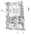
figure 3 shows a perspective view from the bottom and on an enlarged scale of the suspension unit according to the invention applied to a front wheel hub of a vehicle; -
figure 4 shows a perspective view of the suspension unit shown infigure 2 ; -
figure 5 shows a perspective view of a detail of the suspension unit shown infigure 1 ; and -
figure 6 shows a perspective view of an internal portion of the driving cabin of an industrial vehicle equipped with the suspension unit according to the present invention. - With reference to
figures 1 and2 , G generally indicates a suspension unit suitable for being applied and act on each wheel hub MR of the two front wheels of a vehicle V, in particular a vehicle for the commercial and industrial transport, with rear-wheel drive and with the engine (known in the art and not shown in the attached figures) longitudinally placed and mounted on a unitized body S or on a unitized frame by means of support and fixing means known in the art. - According to what shown in
figures 2 and4 , the front part of the bodywork comprises a frame structure T suitable for supporting the longitudinal engine, such structure T being formed by a pair of longitudinal members T1 and T2 connected to each other by a rear cross bar Bt and by a front cradle C substantially saddle-shaped and transversally extending with respect to the longitudinal axis of the vehicle V. - According to what is better shown in
figures 3 and5 , the unit G comprises as associated to each wheel hub MR: - a shock absorber 1, preferably but not limited to, of the hydraulic or oleodynamic type, protected by appropriate covering bellows means, which is placed in a slightly sloped position with respect to the vertical and whose upper part converges towards the shock absorber of the other wheel hub (
figures 1 and2 ), suchupper part 1s being fixed to the vehicle frame V, in particular to thewheelhouse 3; - an
element 4, substantially Y-shaped, to which the lower part li of theshock absorber 1 is fixed; theelement 4 serves as lower arm of the suspension, and is hinged on one side to the frame structure T, and on the other side to the lower pin of the wheel hub MR; - a substantially U-shaped
element 5 for supporting and fixing the shock absorber 1 suitable for connecting the shock absorber 1 itself to the wheel hub MR, and for oscillating with the wheel hub MR itself; - a
transversal leaf spring 6 connected to theelement 4, such leaf spring being preferably of the single-leaf type or of the multi-leaf type, and extending under the cradle C itself, namely transversally with respect to the longitudinal axis X of the vehicle V; - a
stabilizer bar 7 having a curved profile with the concavity facing the front part of the vehicle V,such bar 7 being fixed by means of arod 8 to theshock absorber 1, therod 8 being fixed to the shock absorber 1 in correspondence of the connection point pl placed in an upper position with respect of the fixing point p2 of thesupport element 5. - The advantages deriving from the use of this invention are evident.
Using the suspension unit G described above, since there are no spring means, as shown infigure 6 , the front part of the driving cabin CG, where the control pedals P (clutch, brake and accelerator) are placed, is larger than the prior art, thanks to the reduced dimensions of the wheelhouse deriving from the positioning of the suspension group G for front wheels described above. The driver of the vehicle V, therefore, can drive in a more comfortable and safer way, by removing any possibility of acting on a control pedal and acting also on the adjacent pedal by mistake, because of the reduced space available for the driver's foot.
Moreover, no upper arm of the suspension is present, since it is replaced by thesupport element 5.
The invention thus contrived can be subjected to numerous variations or modification, without departing from the scope of the invention; moreover all the details may be replaced by others technically equivalent.
From the description set forth above it will be possible for the person skilled in the art to embody the invention with no need of describing further construction details.
Claims (8)
- Front suspension unit (G) for a commercial or industrial vehicle (V) with rear-wheel drive of the unitized body (S) type or of the unitized frame type, characterized in that it comprises, coupled to each wheel hub (MR) of at least the front steering wheels of said vehicle (V):- shock-absorbing means (1), an upper end of which is fixed in a wheelhouse (3) of said body;- a lower arm (4), to which a lower part (1i) of said shock absorbing means (1) is fixed, said lower arm being hinged on one side to a frame structure (T), and on the other side to a lower pin of the wheel hub (MR);- support and coupling element (5) of said shock-absorbing means to said wheel hub (MR), said element (5) being suitable for oscillating together with said wheel hub (MR);- leaf spring means (6) connected to said wheel hub (MR) and transversally extending with respect to the longitudinal axis (X) of the vehicle (V).
- Suspension group according to claim 1, characterized in that it further comprises stabilizer means (7) fixed to said shock-absorbing means.
- Suspension unit according to claim 1, characterized in that said leaf spring means (6) are placed inside a transversal cradle (C) suitable for defining a housing of the motor means.
- Suspension unit according to claim 2, characterized in that said cradle (C) is suitable for connecting between each other the two longitudinal members (T1, T2) of said frame structure (T).
- Suspension unit according to any of the previous claims from 1 to 3, characterized in that said support element (5) comprises a substantially U-shaped element.
- Suspension unit according to any of the previous claims from 1 to 4, characterized in that said stabilizer means (7) comprise a bar (7) having a curved profile with the concavity substantially facing the front part of the vehicle (V) and being connected to said shock-absorbing means (1) by means of a rod (8).
- Suspension unit according to claim 4 and 5, characterized in that said rod (8) is fixed to said shock-absorbing means in correspondence of a connection point (p1) on the shock-absorbing means themselves (1) placed in an upper position with respect to the fixing point (p2) of said support element (5) of the shock absorbing means.
- Commercial or industrial vehicle (V) with rear-wheel drive of the unitized body (S) type or of the unitized frame type, characterized in that it comprises the suspension unit according to one or more of the previous claims from 1 to 7, coupled to each wheel hub (MR) of at least the front wheels of the vehicle (V) itself.
Priority Applications (1)
| Application Number | Priority Date | Filing Date | Title |
|---|---|---|---|
| EP09425523A EP2338706A1 (en) | 2009-12-22 | 2009-12-22 | Suspension unit for a front axle of an industrial or commercial vehicle with damper struts and a transverse leaf spring |
Applications Claiming Priority (1)
| Application Number | Priority Date | Filing Date | Title |
|---|---|---|---|
| EP09425523A EP2338706A1 (en) | 2009-12-22 | 2009-12-22 | Suspension unit for a front axle of an industrial or commercial vehicle with damper struts and a transverse leaf spring |
Publications (2)
| Publication Number | Publication Date |
|---|---|
| EP2338706A1 true EP2338706A1 (en) | 2011-06-29 |
| EP2338706A8 EP2338706A8 (en) | 2012-02-15 |
Family
ID=42008508
Family Applications (1)
| Application Number | Title | Priority Date | Filing Date |
|---|---|---|---|
| EP09425523A Ceased EP2338706A1 (en) | 2009-12-22 | 2009-12-22 | Suspension unit for a front axle of an industrial or commercial vehicle with damper struts and a transverse leaf spring |
Country Status (1)
| Country | Link |
|---|---|
| EP (1) | EP2338706A1 (en) |
Cited By (1)
| Publication number | Priority date | Publication date | Assignee | Title |
|---|---|---|---|---|
| CN106061767A (en) * | 2014-02-17 | 2016-10-26 | Zf腓特烈斯哈芬股份公司 | Chassis components of motor vehicles |
Citations (7)
| Publication number | Priority date | Publication date | Assignee | Title |
|---|---|---|---|---|
| GB1205850A (en) | 1967-10-26 | 1970-09-16 | Toyota Motor Co Ltd | Improvements in or relating to suspension springs and suspension systems for vehicles |
| US4813704A (en) * | 1988-06-20 | 1989-03-21 | Chrysler Motors Corporation | Dual strut wheel suspension |
| US4887841A (en) * | 1986-04-23 | 1989-12-19 | Gkn Technology Limited | Vehicle suspension |
| EP0768195A2 (en) * | 1995-10-09 | 1997-04-16 | IGLHAUT GmbH | Four wheel drive vehicle |
| US5879026A (en) * | 1995-12-19 | 1999-03-09 | Chrysler Corporation | Vehicle suspension and steering cradle |
| US6029987A (en) | 1997-05-26 | 2000-02-29 | Dr. Ing. H.C.F. Porsche Ag | Front axle for a motor vehicle |
| FR2832101A1 (en) * | 2001-11-09 | 2003-05-16 | Peugeot Citroen Automobiles Sa | Multi-arm rear wheel axle unit comprises, for each wheel, rear and front transverse arms pivoted by elastic connections to chassis and to wheel pivot and suspension leaf spring |
-
2009
- 2009-12-22 EP EP09425523A patent/EP2338706A1/en not_active Ceased
Patent Citations (7)
| Publication number | Priority date | Publication date | Assignee | Title |
|---|---|---|---|---|
| GB1205850A (en) | 1967-10-26 | 1970-09-16 | Toyota Motor Co Ltd | Improvements in or relating to suspension springs and suspension systems for vehicles |
| US4887841A (en) * | 1986-04-23 | 1989-12-19 | Gkn Technology Limited | Vehicle suspension |
| US4813704A (en) * | 1988-06-20 | 1989-03-21 | Chrysler Motors Corporation | Dual strut wheel suspension |
| EP0768195A2 (en) * | 1995-10-09 | 1997-04-16 | IGLHAUT GmbH | Four wheel drive vehicle |
| US5879026A (en) * | 1995-12-19 | 1999-03-09 | Chrysler Corporation | Vehicle suspension and steering cradle |
| US6029987A (en) | 1997-05-26 | 2000-02-29 | Dr. Ing. H.C.F. Porsche Ag | Front axle for a motor vehicle |
| FR2832101A1 (en) * | 2001-11-09 | 2003-05-16 | Peugeot Citroen Automobiles Sa | Multi-arm rear wheel axle unit comprises, for each wheel, rear and front transverse arms pivoted by elastic connections to chassis and to wheel pivot and suspension leaf spring |
Cited By (2)
| Publication number | Priority date | Publication date | Assignee | Title |
|---|---|---|---|---|
| CN106061767A (en) * | 2014-02-17 | 2016-10-26 | Zf腓特烈斯哈芬股份公司 | Chassis components of motor vehicles |
| CN106061767B (en) * | 2014-02-17 | 2019-08-13 | Zf腓特烈斯哈芬股份公司 | Chassis components for motor vehicles |
Also Published As
| Publication number | Publication date |
|---|---|
| EP2338706A8 (en) | 2012-02-15 |
Similar Documents
| Publication | Publication Date | Title |
|---|---|---|
| EP2338707A1 (en) | Suspension unit for a front axle of an industrial or commercial vehicle with upper and lower V-shaped arms and a transverse leaf spring | |
| US10836226B2 (en) | Semi-trailing arm suspension for a motor vehicle | |
| US4248455A (en) | Heavy-duty suspension system | |
| CN102745032B (en) | Wheel suspension for axle of motor vehicle | |
| US7270341B2 (en) | Vehicle suspension with improved radius arm to axle attachment | |
| US20140327219A1 (en) | Motor-vehicle multi-link suspension system including a transverse leaf spring | |
| KR20100019207A (en) | Lower arm assembly for suspension system | |
| JP2008540201A (en) | Wishbon-type linkage components and suspensions incorporating them | |
| CN104070949A (en) | Independent wheel suspension for the non-driven wheels of a vehicle | |
| KR101201895B1 (en) | Chassis frame for green car | |
| KR20180007252A (en) | Carrier for suspension system of vehicles | |
| EP1789268B1 (en) | Wheel suspension | |
| JPH10258621A (en) | Car steering system | |
| CN102729756A (en) | Rear suspension system for rear-drive off-road vehicle | |
| KR102602979B1 (en) | Suspension system for vehicle with composite spring | |
| EP2338706A1 (en) | Suspension unit for a front axle of an industrial or commercial vehicle with damper struts and a transverse leaf spring | |
| JP7206173B2 (en) | work vehicle | |
| KR101244923B1 (en) | Front suspension structure of green car | |
| JP3961114B2 (en) | Air suspension device | |
| CN204020469U (en) | A kind of trailing arm assembly, vehicle suspension system and use the vehicle of this suspension system | |
| GB2351050A (en) | A rear suspension for a road vehicle | |
| KR102755945B1 (en) | Suspension for vehicle with leaf spring | |
| KR100901578B1 (en) | Trailing Arm Mounting Structure of Vehicle | |
| CN206030986U (en) | Suspension | |
| KR100699482B1 (en) | Car rear suspension |
Legal Events
| Date | Code | Title | Description |
|---|---|---|---|
| PUAI | Public reference made under article 153(3) epc to a published international application that has entered the european phase |
Free format text: ORIGINAL CODE: 0009012 |
|
| AK | Designated contracting states |
Kind code of ref document: A1 Designated state(s): AT BE BG CH CY CZ DE DK EE ES FI FR GB GR HR HU IE IS IT LI LT LU LV MC MK MT NL NO PL PT RO SE SI SK SM TR |
|
| AX | Request for extension of the european patent |
Extension state: AL BA RS |
|
| 17P | Request for examination filed |
Effective date: 20111228 |
|
| RAP1 | Party data changed (applicant data changed or rights of an application transferred) |
Owner name: IVECO S.P.A. |
|
| 17Q | First examination report despatched |
Effective date: 20120208 |
|
| STAA | Information on the status of an ep patent application or granted ep patent |
Free format text: STATUS: THE APPLICATION HAS BEEN REFUSED |
|
| 18R | Application refused |
Effective date: 20130323 |