EP2338566B1 - Dispositif médical implantable avec des moyens pour la reconstruction d'un signal imparfaitement capté - Google Patents
Dispositif médical implantable avec des moyens pour la reconstruction d'un signal imparfaitement capté Download PDFInfo
- Publication number
- EP2338566B1 EP2338566B1 EP10192894.3A EP10192894A EP2338566B1 EP 2338566 B1 EP2338566 B1 EP 2338566B1 EP 10192894 A EP10192894 A EP 10192894A EP 2338566 B1 EP2338566 B1 EP 2338566B1
- Authority
- EP
- European Patent Office
- Prior art keywords
- electromagnetic interference
- imd
- control unit
- detected
- detection
- Prior art date
- Legal status (The legal status is an assumption and is not a legal conclusion. Google has not performed a legal analysis and makes no representation as to the accuracy of the status listed.)
- Active
Links
Images


Classifications
-
- A—HUMAN NECESSITIES
- A61—MEDICAL OR VETERINARY SCIENCE; HYGIENE
- A61N—ELECTROTHERAPY; MAGNETOTHERAPY; RADIATION THERAPY; ULTRASOUND THERAPY
- A61N1/00—Electrotherapy; Circuits therefor
- A61N1/18—Applying electric currents by contact electrodes
- A61N1/32—Applying electric currents by contact electrodes alternating or intermittent currents
- A61N1/36—Applying electric currents by contact electrodes alternating or intermittent currents for stimulation
- A61N1/362—Heart stimulators
- A61N1/37—Monitoring; Protecting
- A61N1/3718—Monitoring of or protection against external electromagnetic fields or currents
Definitions
- the invention relates to a device and a method for dealing with electromagnetic fields, especially those fields that occur in imaging magnetic resonance imaging (hereinafter MRI or MRI) devices.
- MRI imaging magnetic resonance imaging
- MRI examinations are becoming increasingly important in diagnostic medicine, some patients are contraindicated for MRI examinations.
- a contraindication can be given by an at least partially implanted medical device (hereinafter also called an implant or IMD).
- IMD implanted medical device
- other technical applications also pose a danger to users of medical devices or implantable medical devices, especially if they generate strong electromagnetic interference fields (EMI, Electro Magnetic Interference) in your environment.
- EMI Electro Magnetic Interference
- US 20060293591 A1 describes an implantable medical device with a telemetry antenna and a lead with an elongated body comprising a conductor which extends from a proximal connection to a distal electrode.
- US 20040263172 A1 describes a voltage compensation unit which reduces effects caused by induced voltages on a device with a single conductor.
- IMD implantable medical device
- the at least partially implanted medical device included at least one unit for the detection of electromagnetic interference, at least including a sensor or indicator for electromagnetic interference fields and at least one Timepiece, at least one control unit that can be connected to the unit for detecting electromagnetic interference, at least one electrode line that is connected to the control unit and that has an electrode at the other end that is in contact with body tissue and that the electrode is either ins Extends inside the body or is located on the surface of an implant, the control unit only permitting the delivery of electrical stimulation pulses via the at least one electrode in time windows in which no electromagnetic interference is detected and / or the control unit reconstructing electrical signals detected via the at least one electrode Performs measurements for the time window in which electromagnetic interference is detected.
- IMD included at least one unit for the detection of electromagnetic interference, at least including a sensor or indicator for electromagnetic interference fields and at least one Timepiece, at least one control unit that can be connected to the unit for detecting electromagnetic interference, at least one electrode line that is connected to the control unit and that has an electrode at the other end that is in contact with body tissue and that
- the term at least partially implanted includes both fully implanted systems and those in which only components, for example, but not limited to, electrodes, including parts of the electrode lines and / or optical conductors, with sensors and / or actuators and / or stimulators, and / or lines from internal or external medication pumps and / or liquid pumps for diagnosis and / or therapy.
- the liquid pumps can be suitable for conveying liquids from the inside of the body to an analysis unit and / or therapy unit, which can be located both inside and outside the body.
- the at least partially implantable medical device is an external pacemaker and / or external defibrillator or implanted pacemaker and / or defibrillator / cardioverter and / or a cardiac resynchronization therapy device (CRT), a cardiac support system, such as a cardiac support pump, an artificial heart, a neurostimulator , an implanted monitoring device (patient monitor), an implanted medication pump, an implanted fluid pump, and / or an external heart-lung system, and that the control unit of the IMD determines the operating state of the IMD on the basis of the detected electromagnetic interference and / or of the at least one an electrode detects measured values and / or reconstructed measured values from predeterminable operating states.
- CTR cardiac resynchronization therapy device
- the timepiece has a memory that is designed to store time differences, such as therapy intervals and / or intervals of intrinsic system events.
- Therapy intervals are understood to mean the intervals at which therapies are delivered, both individual therapies and groups of therapies being included. Therapy intervals are, for example, but not limited to, RR or QT or TQ time or a corresponding parameter tuple from an IEGM.
- Various intervals are also possible with the intervals of intrinsic system events, such as, but not limited to, individual system events and / or groups of system events, such as QRS or other complexes or complete cardiac cycles and / or pathological events.
- IEGM is generally understood by those skilled in the art to be an intracardiac electrocardiogram.
- the time interval between two electrical stimuli is a therapy interval and that at least the previous therapy interval can be stored.
- the memory is organized as a "first in first out” (fifo).
- control unit uses the data from the timer to calculate the time of the next therapy.
- the calculation of the next therapy point in time is based on a cardiac rhythm estimate and / or a cardiac simulator.
- Parameters for the models for calculating the therapy times are programmable and / or the models for calculating the therapy times use the IEGM and / or EKG and / or reconstructed IEGM measurements for the calculation, ECG data being determined via external aids and at least partially implanted medical device are made available and also data from the patient history from the available information sources, such as, but not limited to, patient files, patient databases and / or patient device, and / or the calculation is based on the parameters and measurements stored in the implant a long-term storage and / or the calculation is based on the parameters and measurements stored in the implant, during the recording of which no electromagnetic interference has been detected.
- the calculation is based on an approximation model of the cardiac restitution and / or a linear or non-linear time series model and / or on a weighted mean of n previous time differences, with n greater than or equal to 1.
- Cardiac restitution is understood by the person skilled in the art to mean the relationship between the action potential duration of cardiac muscle cells as a function of the duration of the preceding diastolic interval - also known graphically as the restitution curve.
- the restitution curve can be used to estimate the repolarization time of the next cardiac cycle, thus avoiding stimulation into the vulnerable phase.
- the restitution curve can also be specified in a modified form depending on the previous RR intervals. In the simplest case, the curve only shows the static relationship between heart rate and repolarization behavior. A model approach with a higher level of detail also takes the dynamic relationships into account.
- the repolarization time also depends on the further past of the cardiac activity (e.g.
- the vulnerable phases of the cardiac excitation cycle are avoided when calculating the next therapy time and / or parameters for the models for calculating the therapy times are programmable and / or the models for calculating the therapy times include the IEGM and / or EKG and / or use reconstructed IEGM measurements for the calculation, whereby ECG data are determined via external aids and made available to the at least partially implanted medical device and also data from the patient history from the available information sources are included, such as patient files, patient databases, and / or Patient device, and / or the calculation is based on the parameters and measurements stored in the implant, specifically from a long-term memory and / or the calculation is based on the parameters and measurements stored in the implant, and no electromagnetic interference is detected when they are recorded have been recognized.
- This version is particularly relevant in connection with the so-called home monitoring, in which data from an implant are sent to a central location at predeterminable intervals and are made available from there or directly to a doctor.
- This exemplary embodiment can ensure that only valid data are forwarded to the patient database or the doctor.
- the stimulation unit is triggerable and / or retriggerable, especially by measurements in time windows without detected electromagnetic interference fields and / or by reconstructed measurement data between the time windows without detected electromagnetic interference fields, and / or the control unit suppresses the stimulation output or triggers a sub-threshold or zero-intensity stimulation output if an intrinsic event was detected by the detection unit of the control unit and / or was identified by the reconstruction of detection gaps.
- Sub-threshold intensity means stimulation pulses which lie below a predeterminable and / or presettable stimulation threshold, while the zero-intensity stimulations are carried out with a non-existent intensity or are only triggered.
- control unit has a priority circuit that temporarily allows therapy even in time windows in which electromagnetic interference have been detected by the unit for the detection of electromagnetic interference, the priority circuit being always activatable and / or only being activatable if an electromagnetic disturbance has been detected by the unit for the detection of electromagnetic interference and the disturbance has been measured under at least one predeterminable sensor value and / or at least one predeterminable indicator value.
- predeterminable should also be understood to mean that one of a plurality of predetermined sensor measured values and / or predetermined indicator values are used as a function of the patient's condition.
- the reconstruction of the measurement data between the time windows without a detected electromagnetic disturbance has at least one of the following properties
- the detection unit additionally has a blanking unit which hides overshoots in detected measurement signals, the blanking unit reflecting the relaxation behavior of the system, such as the electrode system and Input circuit, and / or the nature of the disturbance, such as high-frequency disturbances such as from RF fields, low-frequency disturbances, such as from gradient fields, are taken into account for the reconstruction, depending on the length of the disturbance, a reconstruction method is automatically selected, such as linear or polynomial interpolation, whereby the derivations at the connection points to the measured values are constant, for short interference lengths and pattern recognition of typical measurement curves, such as QRS complexes and / or T-waves and / or p-waves and / or combinations such as QRS-T section un d / or TP section and / or P-QRS section, a pattern recognition is used for the reconstruction, which recognizes typical measurement curves and forwards the recognized
- the IMD is switched to an operating state that is independent of a signal detection if no signal reconstruction from the detected signals is possible, which among other things, but not limited to, in the case of short time windows without electromagnetic interference in combination with at least medium-long periods electromagnetic interference occurs.
- At least one of the following measures is initiated when electromagnetic interference is detected, changing to an MRI-safe state, prolonged remaining in an MRI-safe state or insensitive to electromagnetic interference fields, and the delivery of electromagnetic pulses
- a medical device especially an implant
- the electromagnetic field especially for signaling to an MRI device, with the possibility of transmitting information in addition to the fault in this way and making it visible on the MRI screen.
- the unit for the detection of electromagnetic interference for the detection of electromagnetic fields comprises at least one of the following sensors or indicators, GMR sensor, MagFET sensor, Hall sensor, electro-optical converter as an indicator, the monitoring of battery voltages during capacitor charging processes as an indicator, the detection of RF fields as an indicator, the detection of magnetic gradient fields as an indicator, the detection of currents induced by electromagnetic fields as an indicator, the detection of specific vibrations or components designed as sensors for the detection of vibrations induced by Lorentz forces as an indicator.
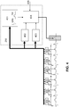
- Figure 1 describes the prior art in which the ICD patient (100) is followed up by a cardiologist before the planned MRI examination and the ICD is switched off (110).
- the MRI examination is performed by a radiologist with a delay of hours to days (120).
- the patient is looked after again by the cardiologist (130) and the ICD is switched on again.
- the patient is without the protection of the implanted defibrillator and largely without rhythm monitoring. This residual risk, measured by the benefits of the MRI scan, is currently accepted.
- the Figure 2 shows a possible interpretation matrix for possible reactions for different ratios of fault gap length and fault length, the fault gap length denoting the periods without disturbances and the disturbance length the length of the occurring and / or perceived electromagnetic interference.
- the type of detection of the electromagnetic interference is not important for the adapted IEGM scanning, in principle all technologies suitable for the detection of electromagnetic interference are possible, particularly but not limited to these, GMR sensors, MagFET sensors, Hall sensors, electro-optical ones Transducers, the monitoring of battery voltages during capacitor charging processes, the detection of RF fields, the detection of magnetic gradient fields, the detection of currents induced by electromagnetic fields, the detection of specific vibrations or components designed as sensors for the detection of vibrations induced by Lorentz forces.
- the matrix indicates, by way of example, the ratios of the gap length to the fault length which are reconstructed, interpolated and / or the original signal is used.
- the Figure 3 shows an exemplary reconstruction of the original signal 210 during the interference.
- the original signal 210 is overlaid by a disturbance 220 in the upper representation, which creates a blanking window 230, that is to say a window in which no signals can be detected that extend beyond the duration of the disturbance 220.
- the blanking window 240 the signal is reconstructed by interpolation, so that a reconstructed section 240 is created.
- the measured original signal 210 is forwarded to a heart simulator 250, and the gap that arises during the blanking window 230 due to the disturbance 220 in the original signal 210 is filled by the heart simulator 250 with the reconstruction 240.
- the reconstruction is an estimate of the T pattern.
- Metric extractors 400 measure continuously or by a trigger such as B. triggered by the interference field detector via signal 405 cardiac cycles with regard to RR intervals, RT intervals, QRS amplitude, width, area, T wave amplitude, width, area, and morphologies, but not limited to these.
- This is input information for the heart simulator 250, in one according to the invention particularly preferred implementation consisting of a morphology database 401, an RR predictor 402 and RT predictor 403.
- the next following RR and RT interval is estimated so that these are immediately available in the event of an upcoming fault.
- the database also prepares the morphologies based on the input information (as normalized curves for e.g. QRS or T-wave reconstruction), which has followed this pattern in the past (in the sense of the highest probability) with a similar previous morphology sequence. This pattern is then scaled and positioned with the results of the RR and RT predictors. Reconstructor 404 realizes this.
- FIG. 5 explains the RT predictor.
- Each RT interval corresponding to the depth of memory is plotted as the ordinate over the previous RR interval as the abscissa.
- the currently valid restitution curve is fitted (e.g. method of least squares). This enables the RT interval of the next cardiac cycle to be determined.
- This process can be implemented as a sliding window or in blocks.
- the RR predictor (not shown) can e.g. B. be implemented as a time series model with the following calculation rule.
- an expanded implementation In addition to RR intervals, an expanded implementation also takes into account RT intervals, QRS amplitude, width, area, T-wave amplitude, width, area, and morphologies (e.g. morphology classes and / or indices such as e.g. defined in the US 2006 / 0047216A1 , but not limited to this). Another expanded implementation also provides for non-linear links between the input information.
- the reconstructor selects the morphology of the signal section to be estimated (e.g. QRS complex or T-wave, etc.) from the database and scales and positions it on the time axis in the missing signal section according to the estimated RT and RR interval values.
- the amplitude scaling takes place on the basis of proportionality which is learned from past signal sections were. So z.
- the amplitude of the reconstructed T-wave is scaled as a percentage of the previous R wave, possibly also taking into account mean values from previous R waves and previous T wave amplitudes.
- the next QRS is first estimated.
- the RT predictor uses this RR interval to estimate the next RT time.
- this continues as in cases g and h.
- this is fixed frequency stimulation, e.g. B. D00, V00 or A00 mode.
- a security stimulus 701 is therefore provided after the watchdog counter 702 has expired. Taking the RR and RT predictors into account, the position of the vulnerable phase into which stimulation should not be used is estimated, as this could otherwise trigger an arrhythmia. Therefore, after the watchdog counter has elapsed, the delivery of this stimulus may be further delayed by a safety distance 703 ( Fig. 7 ).
Landscapes
- Health & Medical Sciences (AREA)
- Cardiology (AREA)
- Heart & Thoracic Surgery (AREA)
- Engineering & Computer Science (AREA)
- Biomedical Technology (AREA)
- Nuclear Medicine, Radiotherapy & Molecular Imaging (AREA)
- Radiology & Medical Imaging (AREA)
- Life Sciences & Earth Sciences (AREA)
- Animal Behavior & Ethology (AREA)
- General Health & Medical Sciences (AREA)
- Public Health (AREA)
- Veterinary Medicine (AREA)
- Electrotherapy Devices (AREA)
Claims (15)
- Appareil médical au moins partiellement implantable (IMD) doté :- d'au moins une unité de reconnaissance de perturbations électromagnétiques (220), contenant au moins un capteur ou un indicateur de champs perturbateurs électromagnétiques et au moins un chronomètre,- d'au moins une unité de commande qui peut être reliée avec l'unité de reconnaissance de perturbations électromagnétiques (220),- d'au moins une ligne d'électrode qui est reliée avec l'unité de commande et qui présente une électrode à l'autre extrémité, oùl'unité de commande est conçue pour effectuer une reconstruction de mesures électriques détectées par le biais de l'au moins une électrode pour les intervalles de temps dans lesquels les perturbations électromagnétiques (220) sont remarquées, caractérisé en ce que
l'unité de commande est conçue pour choisir, de manière automatique, en fonction de l'ampleur de la perturbation, un procédé de reconstruction pour la reconstruction des données de mesure entre des intervalles de temps sans perturbation électromagnétique détectée. - IMD selon la revendication 1, caractérisé en ce que l'appareil médical au moins partiellement implantable est :- un stimulateur cardiaque extérieur ou un défibrillateur extérieur ou un stimulateur cardiaque implantable ou un défibrillateur/cardioverteur ou un appareil thérapeutique de resynchronisation cardiaque (CRT),- un système d'assistance cardiaque tel qu'une pompe d'assistance cardiaque,- un cœur artificiel,- un neuro-stimulateur,- un appareil de surveillance implantable (moniteur pour patient,- une pompe à médicament implantable,- une pompe à liquide implantable ou- un système cœur-poumons externe,et que l'unité de commande de l'IMD choisit l'état de fonctionnement de l'IMD à l'aide de la perturbation électromagnétique détectée et/ou des valeurs de mesure détectées avec l'au moins une électrode et/ou à l'aide de valeurs de mesure reconstruites à partir d'états de fonctionnement pouvant être prédéfinis.
- IMD selon l'une des revendications précédentes, caractérisé en ce que le chronomètre présente une mémoire qui est conçue pour stocker des différences de temps, comme des intervalles de thérapie, et/ou des intervalles d'événements de système intrinsèques.
- IMD selon la revendication 3, caractérisé en ce que l'unité de commande est conçue pour stocker dans la mémoire au moins l'intervalle de thérapie respectivement en cours.
- IMD selon l'une des revendications 3 ou 4, caractérisé en ce que la mémoire est organisée sous forme de « premier entré, premier sorti » (fifo).
- IMD selon l'une des revendications précédentes, caractérisé en ce que l'unité de commande est conçue pour permettre l'administration d'impulsions de stimulation électriques par le biais de l'au moins une électrode uniquement dans des intervalles de temps, dans lesquels aucune perturbation électromagnétique (20) n'est remarquée, où l'unité de commande est conçue pour calculer le moment de la prochaine thérapie avec les données du chronomètre.
- IMD selon la revendication 6, caractérisé en ce que le calcul du moment de la prochaine thérapie repose sur une estimation du rythme cardiaque et/ou sur un stimulateur cardiaque.
- IMD selon l'une des revendications 6 ou 7, caractérisé en ce que le calcul repose sur un modèle d'approximation de la restitution cardiaque et/ou sur un modèle de série chronologique linéaire ou non linéaire, et/ou sur un moyen pondéré de n différences temporelles précédentes avec n supérieur ou égal à 1.
- IMD selon l'une des revendications 6 à 8, caractérisé en ce que l'unité de commande est conçue pour éviter les phases vulnérables du cycle de stimulation cardiaque lors du calcul du prochain moment de thérapie, et/ou
des paramètres sont programmables pour les modèles de calcul des moments de thérapie, et/ou
les modèles de calcul des moments de thérapie tiennent compte des mesures d'IEGM et/ou d'ECG, et/ou d'IEGM reconstruites pour le calcul, où des données d'ECG sont déterminées par le biais de moyens auxiliaires externes et sont mises à disposition de l'appareil médical au moins partiellement implantable et également de données provenant de l'histoire du patient à partir des sources d'informations disponibles, comme des archives de patients, des banques de données de patients et/ou de l'appareil du patient, et/ou
le calcul repose sur des paramètres et des mesures stockés dans l'IMD, et/ou le calcul repose sur des paramètres et des mesures stockés dans l'implant pour la mesure desquels aucune perturbation électromagnétique (220) n'a été détectée. - IMD selon l'une des revendications précédentes, caractérisé en ce que :l'unité de stimulation est conçue pour être déclenchable et/ou redéclenchable, spécialement par des mesures dans des intervalles temporels sans champs perturbateurs électromagnétiques détectés et/ou par des données de mesure reconstruites entre des intervalles de temps sans champs perturbateurs électromagnétiques détectés, et/oul'unité de commande est conçue pour supprimer l'administration d'une stimulation ou délivrer une administration de stimulation de sous-seuil ou d'intensité zéro lorsqu'un évènement intrinsèque a été détecté par une unité de détection de l'unité de commande et/ou a été identifié par la reconstruction de lacunes de détection.
- IMD selon la revendication 10, caractérisé en ce que l'unité de commande possède une commutation de priorité, la commutation de priorité étant conçue pour permettre une thérapie également temporaire dans des intervalles temporels dans lesquels des perturbations électromagnétiques (220) ont été détectées par l'unité de reconnaissance de perturbations électromagnétiques (220), où la commutation de priorité est toujours activable lorsqu'une perturbation électromagnétique a été détectée par l'unité de reconnaissance de perturbations électromagnétiques (220) et la perturbation est au moins en-dessous d'une valeur de mesure de capteur pouvant être prédéterminée et/ou au moins une valeur d'indicateur pouvant être prédéterminée.
- IMD selon l'une des revendications précédentes, caractérisé en ce que l'unité de commande est conçue pour exécuter la reconstruction des données de mesure entre les intervalles temporels sans perturbation électromagnétique détectée avec au moins une des propriétés suivantes :l'unité de détection dispose en outre d'une unité d'obturation qui fait disparaître les sur-oscillations dans les signaux de mesure détectés,une reconnaissance de motif est employée pour la reconstruction, oula reconstruction détermine un motif complémentaire au moyen d'une reconnaissance de motif pour des points de perturbation moyens ou importants sur la base des motifs reconnus.
- IMD selon l'une des revendications précédentes, caractérisé en ce que l'IMD est conçu pour commuter d'un état de fonctionnement indépendant de la détection de signal lorsqu'aucune reconstruction de signal n'est possible à partir des signaux détectés.
- IMD selon l'une des revendications précédentes, caractérisé en ce que l'IMD est conçu pour mettre en œuvre une des mesures suivantes lors d'une reconnaissance de perturbations électromagnétiques (220) :la transition vers un état d'IRM sécurisé,un séjour prolongé dans un état d'IRM sécurisé ou dans un état insensible vis-à-vis de champs perturbateurs électromagnétiques, etla délivrance d'impulsions électromagnétiques pour la signalisation qu'un appareil médical, notamment un implant, est présent dans le champ électromagnétique.
- IMD selon l'une des revendications précédentes, caractérisé en ce que l'unité de reconnaissance de perturbations électromagnétiques (220) pour la détection de champs magnétiques comprend au moins un des capteurs ou indicateurs suivants :- un capteur GMR,- un capteur MagFET,- un capteur de Hall,- un convertisseur électro-optique servant d'indicateur,- la surveillance de tensions de batterie pendant des processus de charge de condensateur servant d'indicateur,- une détection de champs de RF servant d'indicateur,- la détection de champs de gradients magnétiques servant d'indicateur,- la détection de courants induits par des champs électromagnétiques servant d'indicateur,- la détection de vibrations spécifiques ou des composants conçus sous forme de capteurs de détection de vibrations induites par des forces de Lorentz.
Priority Applications (1)
| Application Number | Priority Date | Filing Date | Title |
|---|---|---|---|
| EP19207935.8A EP3628368A1 (fr) | 2009-12-22 | 2010-11-29 | Dispositif médical pouvant être implanté pourvu de moyens de reconstruction d'un signal détecté de manière incomplète |
Applications Claiming Priority (1)
| Application Number | Priority Date | Filing Date | Title |
|---|---|---|---|
| US28885809P | 2009-12-22 | 2009-12-22 |
Related Child Applications (2)
| Application Number | Title | Priority Date | Filing Date |
|---|---|---|---|
| EP19207935.8A Division EP3628368A1 (fr) | 2009-12-22 | 2010-11-29 | Dispositif médical pouvant être implanté pourvu de moyens de reconstruction d'un signal détecté de manière incomplète |
| EP19207935.8A Division-Into EP3628368A1 (fr) | 2009-12-22 | 2010-11-29 | Dispositif médical pouvant être implanté pourvu de moyens de reconstruction d'un signal détecté de manière incomplète |
Publications (2)
| Publication Number | Publication Date |
|---|---|
| EP2338566A1 EP2338566A1 (fr) | 2011-06-29 |
| EP2338566B1 true EP2338566B1 (fr) | 2020-01-08 |
Family
ID=43827513
Family Applications (2)
| Application Number | Title | Priority Date | Filing Date |
|---|---|---|---|
| EP19207935.8A Withdrawn EP3628368A1 (fr) | 2009-12-22 | 2010-11-29 | Dispositif médical pouvant être implanté pourvu de moyens de reconstruction d'un signal détecté de manière incomplète |
| EP10192894.3A Active EP2338566B1 (fr) | 2009-12-22 | 2010-11-29 | Dispositif médical implantable avec des moyens pour la reconstruction d'un signal imparfaitement capté |
Family Applications Before (1)
| Application Number | Title | Priority Date | Filing Date |
|---|---|---|---|
| EP19207935.8A Withdrawn EP3628368A1 (fr) | 2009-12-22 | 2010-11-29 | Dispositif médical pouvant être implanté pourvu de moyens de reconstruction d'un signal détecté de manière incomplète |
Country Status (2)
| Country | Link |
|---|---|
| US (1) | US8423135B2 (fr) |
| EP (2) | EP3628368A1 (fr) |
Families Citing this family (5)
| Publication number | Priority date | Publication date | Assignee | Title |
|---|---|---|---|---|
| ATE539797T1 (de) * | 2009-06-05 | 2012-01-15 | Biotronik Crm Patent Ag | Dispositif ameliore de detection de champ magnetique |
| US8842893B2 (en) * | 2010-04-30 | 2014-09-23 | Medtronic Navigation, Inc. | Method and apparatus for image-based navigation |
| EP2578268B1 (fr) * | 2011-10-06 | 2020-07-22 | BIOTRONIK SE & Co. KG | Capteur de température pour un appareil médical implantable |
| US9652590B2 (en) | 2014-06-26 | 2017-05-16 | General Electric Company | System and method to simulate maintenance of a device |
| US9375181B2 (en) | 2014-10-24 | 2016-06-28 | Medtronic, Inc. | Filtering noise from a signal subjected to blanking |
Family Cites Families (7)
| Publication number | Priority date | Publication date | Assignee | Title |
|---|---|---|---|---|
| US6949929B2 (en) * | 2003-06-24 | 2005-09-27 | Biophan Technologies, Inc. | Magnetic resonance imaging interference immune device |
| US7082328B2 (en) * | 2002-01-29 | 2006-07-25 | Medtronic, Inc. | Methods and apparatus for controlling a pacing system in the presence of EMI |
| SE0300916D0 (sv) * | 2003-03-31 | 2003-03-31 | St Jude Medical | Multi-chamber pacing system |
| US8332011B2 (en) | 2003-09-29 | 2012-12-11 | Medtronic, Inc. | Controlling blanking during magnetic resonance imaging |
| DE102004043005A1 (de) | 2004-09-02 | 2006-03-09 | Biotronik Vi Patent Ag | Signalverarbeitungsvorrichtung für physiologische Signale |
| US20060293591A1 (en) | 2005-05-12 | 2006-12-28 | Wahlstrand John D | Implantable medical device with MRI and gradient field induced capture detection methods |
| US20080154342A1 (en) | 2006-12-21 | 2008-06-26 | Dennis Digby | Implantable medical device comprising magnetic field detector |
-
2010
- 2010-11-29 EP EP19207935.8A patent/EP3628368A1/fr not_active Withdrawn
- 2010-11-29 EP EP10192894.3A patent/EP2338566B1/fr active Active
- 2010-12-18 US US12/972,449 patent/US8423135B2/en active Active
Non-Patent Citations (1)
| Title |
|---|
| None * |
Also Published As
| Publication number | Publication date |
|---|---|
| US8423135B2 (en) | 2013-04-16 |
| EP3628368A1 (fr) | 2020-04-01 |
| US20110153011A1 (en) | 2011-06-23 |
| EP2338566A1 (fr) | 2011-06-29 |
Similar Documents
| Publication | Publication Date | Title |
|---|---|---|
| DE69700748T2 (de) | Egm aufzeichnungssystem für implantierbare medizinische vorrichtung | |
| DE69704170T2 (de) | Leitungsimpedanzmessungssystem für kardiovertier/defibrillator | |
| DE69331961T2 (de) | Frequenzadaptiver Herzschrittmacher gesteuert mittels unipolar gemessener Impedanz | |
| EP2433565B1 (fr) | Appareil médical implantable | |
| DE3686951T2 (de) | Vorrichtung zum erkennen der abstossungsreaktion nach herztransplantation. | |
| EP2338414B1 (fr) | Capteur de position pour la reconnaissance MRT | |
| EP2338566B1 (fr) | Dispositif médical implantable avec des moyens pour la reconstruction d'un signal imparfaitement capté | |
| EP2338563A2 (fr) | Signalisation IRM | |
| EP2123324B1 (fr) | Appareil de commande de direction | |
| EP3025759A1 (fr) | Appareil implantable actif adapté pour une utilisation avec irm | |
| EP2364643B1 (fr) | Implant électromédical et système de surveillance doté de cet implant électromédical | |
| EP3542716A1 (fr) | Appareil médical et procédé d'évaluation de données concernant des erreurs dans un fil d'électrode | |
| EP2338558A1 (fr) | Détecteur pour champs électromagnétiques | |
| EP1262143B1 (fr) | Methode et appareil pour la mémorisation de données en provenance d'un signal cardiaque | |
| EP2338560B1 (fr) | Défibrillateur cardioverseur implantable (ICD) avec unité de détection d'interférence IRM | |
| EP2140910B1 (fr) | Stimulateur cardiaque destiné au traitement des rythmes tachycardiques | |
| EP0793979A2 (fr) | Appareil pour la détermination de la fréquence cardiaque | |
| DE10046241A1 (de) | Herzschrittmachersystem mit verbesserter Klassifizierung physiologischer Ereignisse und verbesserter Herzüberwachung, basierend auf DSP | |
| EP2502646A2 (fr) | Appareil implantable | |
| EP2422843B1 (fr) | Appareil de thérapie électronique implantable | |
| EP3725368A1 (fr) | Dispositif pouvant être implanté destiné à la stimulation d'un c ur humain ou animal | |
| EP2338561B1 (fr) | Dispositif médical implantable avec un mode bruit prolongé | |
| EP3025757A1 (fr) | Appareil actif implantable pour mrt et capteur mrt | |
| EP3733240B1 (fr) | Dispositif pouvant être implanté destiné à la stimulation d'un c ur humain ou animal | |
| EP2250962B1 (fr) | Détecteur de dispersion à ondes P implantable |
Legal Events
| Date | Code | Title | Description |
|---|---|---|---|
| PUAI | Public reference made under article 153(3) epc to a published international application that has entered the european phase |
Free format text: ORIGINAL CODE: 0009012 |
|
| AK | Designated contracting states |
Kind code of ref document: A1 Designated state(s): AL AT BE BG CH CY CZ DE DK EE ES FI FR GB GR HR HU IE IS IT LI LT LU LV MC MK MT NL NO PL PT RO RS SE SI SK SM TR |
|
| AX | Request for extension of the european patent |
Extension state: BA ME |
|
| 17P | Request for examination filed |
Effective date: 20111214 |
|
| STAA | Information on the status of an ep patent application or granted ep patent |
Free format text: STATUS: EXAMINATION IS IN PROGRESS |
|
| 17Q | First examination report despatched |
Effective date: 20170515 |
|
| RAP1 | Party data changed (applicant data changed or rights of an application transferred) |
Owner name: BIOTRONIK SE & CO. KG |
|
| GRAP | Despatch of communication of intention to grant a patent |
Free format text: ORIGINAL CODE: EPIDOSNIGR1 |
|
| STAA | Information on the status of an ep patent application or granted ep patent |
Free format text: STATUS: GRANT OF PATENT IS INTENDED |
|
| INTG | Intention to grant announced |
Effective date: 20190717 |
|
| GRAS | Grant fee paid |
Free format text: ORIGINAL CODE: EPIDOSNIGR3 |
|
| GRAA | (expected) grant |
Free format text: ORIGINAL CODE: 0009210 |
|
| STAA | Information on the status of an ep patent application or granted ep patent |
Free format text: STATUS: THE PATENT HAS BEEN GRANTED |
|
| AK | Designated contracting states |
Kind code of ref document: B1 Designated state(s): AL AT BE BG CH CY CZ DE DK EE ES FI FR GB GR HR HU IE IS IT LI LT LU LV MC MK MT NL NO PL PT RO RS SE SI SK SM TR |
|
| REG | Reference to a national code |
Ref country code: GB Ref legal event code: FG4D Free format text: NOT ENGLISH |
|
| REG | Reference to a national code |
Ref country code: CH Ref legal event code: EP |
|
| REG | Reference to a national code |
Ref country code: DE Ref legal event code: R096 Ref document number: 502010016445 Country of ref document: DE |
|
| REG | Reference to a national code |
Ref country code: IE Ref legal event code: FG4D Free format text: LANGUAGE OF EP DOCUMENT: GERMAN |
|
| REG | Reference to a national code |
Ref country code: AT Ref legal event code: REF Ref document number: 1221946 Country of ref document: AT Kind code of ref document: T Effective date: 20200215 |
|
| REG | Reference to a national code |
Ref country code: NL Ref legal event code: MP Effective date: 20200108 |
|
| REG | Reference to a national code |
Ref country code: LT Ref legal event code: MG4D |
|
| PG25 | Lapsed in a contracting state [announced via postgrant information from national office to epo] |
Ref country code: FI Free format text: LAPSE BECAUSE OF FAILURE TO SUBMIT A TRANSLATION OF THE DESCRIPTION OR TO PAY THE FEE WITHIN THE PRESCRIBED TIME-LIMIT Effective date: 20200108 Ref country code: LT Free format text: LAPSE BECAUSE OF FAILURE TO SUBMIT A TRANSLATION OF THE DESCRIPTION OR TO PAY THE FEE WITHIN THE PRESCRIBED TIME-LIMIT Effective date: 20200108 Ref country code: NL Free format text: LAPSE BECAUSE OF FAILURE TO SUBMIT A TRANSLATION OF THE DESCRIPTION OR TO PAY THE FEE WITHIN THE PRESCRIBED TIME-LIMIT Effective date: 20200108 Ref country code: PT Free format text: LAPSE BECAUSE OF FAILURE TO SUBMIT A TRANSLATION OF THE DESCRIPTION OR TO PAY THE FEE WITHIN THE PRESCRIBED TIME-LIMIT Effective date: 20200531 Ref country code: RS Free format text: LAPSE BECAUSE OF FAILURE TO SUBMIT A TRANSLATION OF THE DESCRIPTION OR TO PAY THE FEE WITHIN THE PRESCRIBED TIME-LIMIT Effective date: 20200108 Ref country code: NO Free format text: LAPSE BECAUSE OF FAILURE TO SUBMIT A TRANSLATION OF THE DESCRIPTION OR TO PAY THE FEE WITHIN THE PRESCRIBED TIME-LIMIT Effective date: 20200408 |
|
| PG25 | Lapsed in a contracting state [announced via postgrant information from national office to epo] |
Ref country code: BG Free format text: LAPSE BECAUSE OF FAILURE TO SUBMIT A TRANSLATION OF THE DESCRIPTION OR TO PAY THE FEE WITHIN THE PRESCRIBED TIME-LIMIT Effective date: 20200408 Ref country code: IS Free format text: LAPSE BECAUSE OF FAILURE TO SUBMIT A TRANSLATION OF THE DESCRIPTION OR TO PAY THE FEE WITHIN THE PRESCRIBED TIME-LIMIT Effective date: 20200508 Ref country code: SE Free format text: LAPSE BECAUSE OF FAILURE TO SUBMIT A TRANSLATION OF THE DESCRIPTION OR TO PAY THE FEE WITHIN THE PRESCRIBED TIME-LIMIT Effective date: 20200108 Ref country code: HR Free format text: LAPSE BECAUSE OF FAILURE TO SUBMIT A TRANSLATION OF THE DESCRIPTION OR TO PAY THE FEE WITHIN THE PRESCRIBED TIME-LIMIT Effective date: 20200108 Ref country code: GR Free format text: LAPSE BECAUSE OF FAILURE TO SUBMIT A TRANSLATION OF THE DESCRIPTION OR TO PAY THE FEE WITHIN THE PRESCRIBED TIME-LIMIT Effective date: 20200409 Ref country code: LV Free format text: LAPSE BECAUSE OF FAILURE TO SUBMIT A TRANSLATION OF THE DESCRIPTION OR TO PAY THE FEE WITHIN THE PRESCRIBED TIME-LIMIT Effective date: 20200108 |
|
| REG | Reference to a national code |
Ref country code: DE Ref legal event code: R097 Ref document number: 502010016445 Country of ref document: DE |
|
| PG25 | Lapsed in a contracting state [announced via postgrant information from national office to epo] |
Ref country code: CZ Free format text: LAPSE BECAUSE OF FAILURE TO SUBMIT A TRANSLATION OF THE DESCRIPTION OR TO PAY THE FEE WITHIN THE PRESCRIBED TIME-LIMIT Effective date: 20200108 Ref country code: DK Free format text: LAPSE BECAUSE OF FAILURE TO SUBMIT A TRANSLATION OF THE DESCRIPTION OR TO PAY THE FEE WITHIN THE PRESCRIBED TIME-LIMIT Effective date: 20200108 Ref country code: SM Free format text: LAPSE BECAUSE OF FAILURE TO SUBMIT A TRANSLATION OF THE DESCRIPTION OR TO PAY THE FEE WITHIN THE PRESCRIBED TIME-LIMIT Effective date: 20200108 Ref country code: EE Free format text: LAPSE BECAUSE OF FAILURE TO SUBMIT A TRANSLATION OF THE DESCRIPTION OR TO PAY THE FEE WITHIN THE PRESCRIBED TIME-LIMIT Effective date: 20200108 Ref country code: SK Free format text: LAPSE BECAUSE OF FAILURE TO SUBMIT A TRANSLATION OF THE DESCRIPTION OR TO PAY THE FEE WITHIN THE PRESCRIBED TIME-LIMIT Effective date: 20200108 Ref country code: RO Free format text: LAPSE BECAUSE OF FAILURE TO SUBMIT A TRANSLATION OF THE DESCRIPTION OR TO PAY THE FEE WITHIN THE PRESCRIBED TIME-LIMIT Effective date: 20200108 Ref country code: ES Free format text: LAPSE BECAUSE OF FAILURE TO SUBMIT A TRANSLATION OF THE DESCRIPTION OR TO PAY THE FEE WITHIN THE PRESCRIBED TIME-LIMIT Effective date: 20200108 |
|
| PLBE | No opposition filed within time limit |
Free format text: ORIGINAL CODE: 0009261 |
|
| STAA | Information on the status of an ep patent application or granted ep patent |
Free format text: STATUS: NO OPPOSITION FILED WITHIN TIME LIMIT |
|
| 26N | No opposition filed |
Effective date: 20201009 |
|
| PG25 | Lapsed in a contracting state [announced via postgrant information from national office to epo] |
Ref country code: IT Free format text: LAPSE BECAUSE OF FAILURE TO SUBMIT A TRANSLATION OF THE DESCRIPTION OR TO PAY THE FEE WITHIN THE PRESCRIBED TIME-LIMIT Effective date: 20200108 |
|
| PG25 | Lapsed in a contracting state [announced via postgrant information from national office to epo] |
Ref country code: PL Free format text: LAPSE BECAUSE OF FAILURE TO SUBMIT A TRANSLATION OF THE DESCRIPTION OR TO PAY THE FEE WITHIN THE PRESCRIBED TIME-LIMIT Effective date: 20200108 Ref country code: SI Free format text: LAPSE BECAUSE OF FAILURE TO SUBMIT A TRANSLATION OF THE DESCRIPTION OR TO PAY THE FEE WITHIN THE PRESCRIBED TIME-LIMIT Effective date: 20200108 |
|
| PG25 | Lapsed in a contracting state [announced via postgrant information from national office to epo] |
Ref country code: MC Free format text: LAPSE BECAUSE OF FAILURE TO SUBMIT A TRANSLATION OF THE DESCRIPTION OR TO PAY THE FEE WITHIN THE PRESCRIBED TIME-LIMIT Effective date: 20200108 |
|
| GBPC | Gb: european patent ceased through non-payment of renewal fee |
Effective date: 20201129 |
|
| PG25 | Lapsed in a contracting state [announced via postgrant information from national office to epo] |
Ref country code: LU Free format text: LAPSE BECAUSE OF NON-PAYMENT OF DUE FEES Effective date: 20201129 |
|
| REG | Reference to a national code |
Ref country code: BE Ref legal event code: MM Effective date: 20201130 |
|
| PG25 | Lapsed in a contracting state [announced via postgrant information from national office to epo] |
Ref country code: FR Free format text: LAPSE BECAUSE OF NON-PAYMENT OF DUE FEES Effective date: 20201130 |
|
| PG25 | Lapsed in a contracting state [announced via postgrant information from national office to epo] |
Ref country code: GB Free format text: LAPSE BECAUSE OF NON-PAYMENT OF DUE FEES Effective date: 20201129 |
|
| REG | Reference to a national code |
Ref country code: AT Ref legal event code: MM01 Ref document number: 1221946 Country of ref document: AT Kind code of ref document: T Effective date: 20201129 |
|
| PG25 | Lapsed in a contracting state [announced via postgrant information from national office to epo] |
Ref country code: AT Free format text: LAPSE BECAUSE OF NON-PAYMENT OF DUE FEES Effective date: 20201129 |
|
| PGFP | Annual fee paid to national office [announced via postgrant information from national office to epo] |
Ref country code: DE Payment date: 20211126 Year of fee payment: 12 Ref country code: IE Payment date: 20211118 Year of fee payment: 12 |
|
| PGFP | Annual fee paid to national office [announced via postgrant information from national office to epo] |
Ref country code: CH Payment date: 20211123 Year of fee payment: 12 |
|
| PG25 | Lapsed in a contracting state [announced via postgrant information from national office to epo] |
Ref country code: TR Free format text: LAPSE BECAUSE OF FAILURE TO SUBMIT A TRANSLATION OF THE DESCRIPTION OR TO PAY THE FEE WITHIN THE PRESCRIBED TIME-LIMIT Effective date: 20200108 Ref country code: MT Free format text: LAPSE BECAUSE OF FAILURE TO SUBMIT A TRANSLATION OF THE DESCRIPTION OR TO PAY THE FEE WITHIN THE PRESCRIBED TIME-LIMIT Effective date: 20200108 Ref country code: CY Free format text: LAPSE BECAUSE OF FAILURE TO SUBMIT A TRANSLATION OF THE DESCRIPTION OR TO PAY THE FEE WITHIN THE PRESCRIBED TIME-LIMIT Effective date: 20200108 |
|
| PG25 | Lapsed in a contracting state [announced via postgrant information from national office to epo] |
Ref country code: MK Free format text: LAPSE BECAUSE OF FAILURE TO SUBMIT A TRANSLATION OF THE DESCRIPTION OR TO PAY THE FEE WITHIN THE PRESCRIBED TIME-LIMIT Effective date: 20200108 Ref country code: AL Free format text: LAPSE BECAUSE OF FAILURE TO SUBMIT A TRANSLATION OF THE DESCRIPTION OR TO PAY THE FEE WITHIN THE PRESCRIBED TIME-LIMIT Effective date: 20200108 |
|
| PG25 | Lapsed in a contracting state [announced via postgrant information from national office to epo] |
Ref country code: BE Free format text: LAPSE BECAUSE OF NON-PAYMENT OF DUE FEES Effective date: 20201130 |
|
| REG | Reference to a national code |
Ref country code: DE Ref legal event code: R119 Ref document number: 502010016445 Country of ref document: DE |
|
| REG | Reference to a national code |
Ref country code: CH Ref legal event code: PL |
|
| PG25 | Lapsed in a contracting state [announced via postgrant information from national office to epo] |
Ref country code: LI Free format text: LAPSE BECAUSE OF NON-PAYMENT OF DUE FEES Effective date: 20221130 Ref country code: CH Free format text: LAPSE BECAUSE OF NON-PAYMENT OF DUE FEES Effective date: 20221130 |
|
| PG25 | Lapsed in a contracting state [announced via postgrant information from national office to epo] |
Ref country code: IE Free format text: LAPSE BECAUSE OF NON-PAYMENT OF DUE FEES Effective date: 20221129 Ref country code: DE Free format text: LAPSE BECAUSE OF NON-PAYMENT OF DUE FEES Effective date: 20230601 |