EP2502646A2 - Appareil implantable - Google Patents
Appareil implantable Download PDFInfo
- Publication number
- EP2502646A2 EP2502646A2 EP12159241A EP12159241A EP2502646A2 EP 2502646 A2 EP2502646 A2 EP 2502646A2 EP 12159241 A EP12159241 A EP 12159241A EP 12159241 A EP12159241 A EP 12159241A EP 2502646 A2 EP2502646 A2 EP 2502646A2
- Authority
- EP
- European Patent Office
- Prior art keywords
- unit
- test
- mri
- implantable
- control unit
- Prior art date
- Legal status (The legal status is an assumption and is not a legal conclusion. Google has not performed a legal analysis and makes no representation as to the accuracy of the status listed.)
- Granted
Links
- 238000012360 testing method Methods 0.000 claims abstract description 59
- 238000001514 detection method Methods 0.000 claims abstract description 30
- 230000000694 effects Effects 0.000 claims abstract description 7
- 230000005672 electromagnetic field Effects 0.000 claims abstract description 5
- 239000007943 implant Substances 0.000 claims description 44
- 238000002560 therapeutic procedure Methods 0.000 claims description 34
- 230000000638 stimulation Effects 0.000 claims description 23
- 230000010358 mechanical oscillation Effects 0.000 claims description 12
- 206010030113 Oedema Diseases 0.000 claims description 10
- 230000015572 biosynthetic process Effects 0.000 claims description 6
- 238000002847 impedance measurement Methods 0.000 claims description 6
- 238000012544 monitoring process Methods 0.000 claims description 6
- 230000008602 contraction Effects 0.000 claims description 5
- 230000009471 action Effects 0.000 claims description 3
- 210000005242 cardiac chamber Anatomy 0.000 claims description 3
- 230000010354 integration Effects 0.000 claims description 3
- 230000004936 stimulating effect Effects 0.000 claims 1
- 238000002595 magnetic resonance imaging Methods 0.000 description 66
- 238000000034 method Methods 0.000 description 21
- 230000000747 cardiac effect Effects 0.000 description 16
- 239000004020 conductor Substances 0.000 description 15
- 210000005003 heart tissue Anatomy 0.000 description 10
- 210000001519 tissue Anatomy 0.000 description 10
- 210000005241 right ventricle Anatomy 0.000 description 7
- 230000002861 ventricular Effects 0.000 description 7
- 238000003745 diagnosis Methods 0.000 description 5
- 238000010438 heat treatment Methods 0.000 description 5
- 230000008859 change Effects 0.000 description 4
- 230000001960 triggered effect Effects 0.000 description 4
- 230000005540 biological transmission Effects 0.000 description 3
- 238000001816 cooling Methods 0.000 description 3
- 125000004122 cyclic group Chemical group 0.000 description 3
- 210000004165 myocardium Anatomy 0.000 description 3
- 239000008280 blood Substances 0.000 description 2
- 210000004369 blood Anatomy 0.000 description 2
- 230000003247 decreasing effect Effects 0.000 description 2
- 230000006870 function Effects 0.000 description 2
- 230000000116 mitigating effect Effects 0.000 description 2
- 238000012552 review Methods 0.000 description 2
- 208000032366 Oversensing Diseases 0.000 description 1
- 208000032364 Undersensing Diseases 0.000 description 1
- 230000008901 benefit Effects 0.000 description 1
- 238000002405 diagnostic procedure Methods 0.000 description 1
- 230000009977 dual effect Effects 0.000 description 1
- 230000005684 electric field Effects 0.000 description 1
- 238000005265 energy consumption Methods 0.000 description 1
- 238000005516 engineering process Methods 0.000 description 1
- 238000011156 evaluation Methods 0.000 description 1
- 238000003384 imaging method Methods 0.000 description 1
- 230000007794 irritation Effects 0.000 description 1
- 210000005240 left ventricle Anatomy 0.000 description 1
- 238000005259 measurement Methods 0.000 description 1
- 239000002184 metal Substances 0.000 description 1
- 238000010606 normalization Methods 0.000 description 1
- 230000008569 process Effects 0.000 description 1
- 210000005245 right atrium Anatomy 0.000 description 1
- 230000001225 therapeutic effect Effects 0.000 description 1
- 238000010792 warming Methods 0.000 description 1
Images


Classifications
-
- A—HUMAN NECESSITIES
- A61—MEDICAL OR VETERINARY SCIENCE; HYGIENE
- A61N—ELECTROTHERAPY; MAGNETOTHERAPY; RADIATION THERAPY; ULTRASOUND THERAPY
- A61N1/00—Electrotherapy; Circuits therefor
- A61N1/02—Details
- A61N1/025—Digital circuitry features of electrotherapy devices, e.g. memory, clocks, processors
-
- A—HUMAN NECESSITIES
- A61—MEDICAL OR VETERINARY SCIENCE; HYGIENE
- A61N—ELECTROTHERAPY; MAGNETOTHERAPY; RADIATION THERAPY; ULTRASOUND THERAPY
- A61N1/00—Electrotherapy; Circuits therefor
- A61N1/18—Applying electric currents by contact electrodes
- A61N1/32—Applying electric currents by contact electrodes alternating or intermittent currents
- A61N1/36—Applying electric currents by contact electrodes alternating or intermittent currents for stimulation
- A61N1/362—Heart stimulators
- A61N1/37—Monitoring; Protecting
- A61N1/3718—Monitoring of or protection against external electromagnetic fields or currents
-
- A—HUMAN NECESSITIES
- A61—MEDICAL OR VETERINARY SCIENCE; HYGIENE
- A61N—ELECTROTHERAPY; MAGNETOTHERAPY; RADIATION THERAPY; ULTRASOUND THERAPY
- A61N1/00—Electrotherapy; Circuits therefor
- A61N1/18—Applying electric currents by contact electrodes
- A61N1/32—Applying electric currents by contact electrodes alternating or intermittent currents
- A61N1/36—Applying electric currents by contact electrodes alternating or intermittent currents for stimulation
- A61N1/362—Heart stimulators
- A61N1/37—Monitoring; Protecting
-
- A—HUMAN NECESSITIES
- A61—MEDICAL OR VETERINARY SCIENCE; HYGIENE
- A61N—ELECTROTHERAPY; MAGNETOTHERAPY; RADIATION THERAPY; ULTRASOUND THERAPY
- A61N1/00—Electrotherapy; Circuits therefor
- A61N1/18—Applying electric currents by contact electrodes
- A61N1/32—Applying electric currents by contact electrodes alternating or intermittent currents
- A61N1/36—Applying electric currents by contact electrodes alternating or intermittent currents for stimulation
- A61N1/372—Arrangements in connection with the implantation of stimulators
- A61N1/37211—Means for communicating with stimulators
- A61N1/37252—Details of algorithms or data aspects of communication system, e.g. handshaking, transmitting specific data or segmenting data
- A61N1/37282—Details of algorithms or data aspects of communication system, e.g. handshaking, transmitting specific data or segmenting data characterised by communication with experts in remote locations using a network
-
- A—HUMAN NECESSITIES
- A61—MEDICAL OR VETERINARY SCIENCE; HYGIENE
- A61B—DIAGNOSIS; SURGERY; IDENTIFICATION
- A61B2560/00—Constructional details of operational features of apparatus; Accessories for medical measuring apparatus
- A61B2560/06—Accessories for medical measuring apparatus
- A61B2560/063—Devices specially adapted for delivering implantable medical measuring apparatus
- A61B2560/066—Devices specially adapted for delivering implantable medical measuring apparatus catheters therefor
Definitions
- the invention relates to an implantable electromedical device with a control unit which is connected to a diagnostic or therapy unit of a test unit.
- the control unit is connected to an MRI detection unit for detecting MRT-typical magnetic and / or electromagnetic fields and / or mechanical oscillations.
- the MRI detection unit can have an MRT sensor for this purpose.
- the test unit is designed to test the diagnostic therapy unit or components of the diagnostic therapy unit and to output test results thus obtained for storage (to a memory unit).
- the diagnostic or therapy unit has components such as sensor units and / or therapy delivery units and is designed to receive physiological parameters and / or to effect a therapy delivery.
- the control unit is designed to control the test unit for testing the diagnostic therapy unit.
- Such implantable medical devices are, for example, implantable defibrillators (ICDs) or cardiac pacemakers, which can deliver electrical stimulation pulses to heart tissue (myocardium) via electrode leads or can detect electrical potentials in cardiac tissue via corresponding sensors.
- Other implants such as neurostimulators serve to stimulate other tissues.
- ICDs implantable defibrillators
- cardiac pacemakers it is known that these automatically automatic aftercare eg as so - called chronjobs, ie perform in terms of timing and timing preprogrammed self - tests, as usual under current guidelines, certain parameters such as threshold, lead impedance, battery voltage, signal amplitudes, etc . are recorded.
- the test unit controlled by the control unit serves this purpose.
- Implantable cardiac pacemakers or defibrillators are typically connected to electrode lines for electrostimulation, which entail the disadvantage that their electrical conductor can heat up in an MRI scanner (also referred to as a magnetic resonance tomograph) because the magnetic fields prevailing in the MRI scanner in the electrical conductor are not insignificant induce electrical currents. Also, such induced currents can be delivered via electrode poles of the electrode line to surrounding tissue and thus, for example, lead to undesired tissue warming. Also, induced currents could affect or destroy components of the device, or electrical resistance could change between potential sensing or pulse emitting electrode poles on the electrode lead, e.g. increase. This would impair the detection or evaluation of electrical signals of a heart and thus the therapy control or the therapy delivery. Therefore, cardiac pacemaker patients today can usually not be examined or only to a limited extent in a magnetic resonance tomograph.
- implantable pacemakers or defibrillators are typically connected at least to such a stimulation electrode lead which has a standardized electrical connection at its proximal end for connection to the pacemaker or defibrillator and at its distal end provided for placement in the heart has one or more electrode poles.
- Such an electrode pole serves to deliver electrical impulses to the tissue (myocardium) of the heart or to sense electric fields in order to be able to sense an activity of a heart within the scope of so-called sensing.
- electrode poles typically form electrically conductive surface portions of an electrode lead.
- Electrode poles are typically provided as a ring electrode in the form of a ring around the electrode lead or in the form of a tip or tip electrode at the distal end of the electrode lead.
- the electrode poles are electrically conductively connected via one or more electrical conductors to contacts of the electrical connection of the electrode line at its proximal end.
- the electrode leads extend at the proximal end thereof and the electrode poles at the distal end of the electrode lead one or more electrical leads Conductors electrically connecting one or more of the electrode poles to one or more of the contacts.
- These electrical conductors can be used, on the one hand, to transmit stimulation pulses to the electrode poles and, on the other hand, to transmit electrical signals picked up by the electrode poles to the proximal end of the electrode line.
- the invention has for its object to realize a safe MRI examination of patients with electronic implants.
- the MRI detection unit may have an MRI sensor, as it. for example US 12 / 970,290 is known.
- the diagnostic therapy unit can be a pure diagnostic unit or a pure therapy unit, eg a stimulation unit of a cardiac pacemaker or a combination of both.
- the diagnostic unit can be, for example, a sensing unit known from cardiac pacemakers for detecting and optionally evaluating cardiac events indicative of electrical potentials.
- the implantable medical device is capable of automatically detecting MRI-typical (and similar) magnetic and / or electromagnetic alternating fields and / or mechanical oscillations and subsequently values of more importantly detecting the system integrity parameters characterizing an operability of the implantable medical device and thus creates the prerequisite for being able to recognize a change in these values as a result of the action of such fields on the device.
- the MRI scan has been used in patients with electronic implants, e.g. Cardiac pacemakers, ICDs, CRT-Ds or neurostimulators are contraindicated because of problems in the vicinity of the MRI, such as the heating of the electrode tip caused by the strong electromagnetic fields in MRI.
- the heating of the electrode tip can lead to a temporary or permanent threshold increase, undersensing or oversensing or even dislocation.
- the latter can automatically detect the device according to the invention and thus permits, for example, the checking of an implant and electrode system after the MRI examination has taken place in order to detect system errors of the electronic implant and MRI-induced electrode problems.
- an implant specialist here cardiologist / electrophysiologist
- MRI is typically performed by radiologists who are not trained and have the authority to review the implant functionality of an electronic implant. Therefore, the patient must typically visit a second specialist before, but especially after the MRI examination. This significantly increases the procedure costs for the MRI and involves the risk that the post-examination will not takes place.
- the device according to the invention makes such a preliminary examination by a specialist before an MRI procedure superfluous.
- FIG. 3 for a better understanding of the currently prescribed procedure of a pre- and post-examination of an implantable medical device before and after an MRI procedure.
- a patient is examined by an implant specialist immediately prior to a planned MRI procedure (110).
- the system integrity and electrode measurements are recorded as a reference for later comparison with the results of the follow-up examination.
- the implant may also be programmed in a so-called MRI-safe mode.
- the implant specialist will need to perform follow-up care (130) on the implant system and system integrity, etc., in accordance with applicable regulations. evaluate by comparison with the initially determined values.
- the overall procedure involves two additional procedures with an implant specialist and requires that the implant specialist and radiologist work closely together in terms of time and space, something that can only be achieved in practice with significantly increased effort.
- the implantable electromedical device is designed to detect an omission of an MRT-typical magnetic and / or electromagnetic alternating field and / or mechanical oscillations indicating output signal of the MRI detection unit and then a post-test of preferably that component of the diagnostic therapy unit by the Test unit to be triggered, in which a pre-test has been performed and in which preferably values of those system integrity parameters are recorded, to which values from a pre-test are present.
- a pre-test has been performed and in which preferably values of those system integrity parameters are recorded, to which values from a pre-test are present.
- Such an implantable electromedical device also makes a local follow-up by, for example, a cardiologist superfluous or at least relieved. Values detected by the implantable electromedical device during pre- and post-test can namely transmitted telemetrically to a central service center and evaluated there automatically or by a doctor.
- the controller is configured to place the implantable medical device in a post-MRI mode of operation subsequent to a post-test in which cyclic post-tests are performed, the control unit being further configured to output values of a respective system integrity parameter compare a respective post-test with a corresponding value of the same system integrity parameter from the last pre-test.
- the implantable medical device may be able to automatically detect critical changes in values of the system integrity parameters.
- control unit is preferably designed to terminate the post-MRI operating mode if a deviation of the values lies below a predefined threshold value.
- the implantable electromedical device is a stimulator or monitoring implant having a tissue-contacting electrode pad or terminal for a tissue-contacting electrode pad
- the or one of the system integrity parameters is preferably an impedance value characterizing an electrode-tissue contact. This preferred embodiment is based on the recognition that the impedance value between an electrode pole and adjacent tissue can change particularly as a result of MRT-related heating and can assume critical values.
- control unit is designed to set the implantable medical device to an MRT-typical magnetic and / or electromagnetic alternating field and / or mechanical oscillations indicating output signal of the MRI detection unit in an MRI operating mode, wherein the The control unit is further configured to cause a detection of an impedance value characterizing an electrode-tissue contact during the MRI operating mode and to evaluate detected impedance values with regard to an impedance value change indicative of local edema formation.
- an implantable medical device may already undergo critical changes during an MRI procedure and, if necessary, detect edema formation and, if necessary, initiate appropriate countermeasures such as tissue cooling or termination of the MRI procedure. The latter can be done, for example, in that the implantable medical device emits control signals to an MRI scanner or emits perceptible signals to the operating personnel of a magnetic resonance tomograph.
- control unit is preferably designed to detect an omission of an MRT-type magnetic and / or electromagnetic alternating field and / or mechanical oscillations indicating output signal of the MRI detection unit and then terminate the MRT mode of operation.
- control unit configured to detect changes in impedance value indicative of local edema
- the control unit is preferably further configured to induce edema-alleviating measures, particularly tissue cooling in the region of an affected electrode pole, as soon as it senses changes in impedance value indicative of local edema formation Has.
- the implantable medical device has a telemetry unit connected and configured to transmit values of one or more system integration parameters to an external device. Then these values could be evaluated in a central service center and / or transmitted to a supervising physician.
- the telemetry unit is connected to the control unit and configured to receive control commands from an external device; so that the implantable medical device can be controlled by means of control commands from outside, possibly also remotely controlled by a central service center, as indicated by the detected values of the system integrity parameters.
- the test unit preferably has or is connected to an impedance determination unit. As related to below FIG. 2 can be described with the aid of such an impedance determination unit a number of values of system integrity parameters are detected.
- the implantable electromedical device is a heart stimulator that is configured to deliver stimulation pulses that may cause a stimulated contraction of a heart chamber
- the test unit is preferably configured to perform an automatic stimulation performance check.
- automatic stimulation success control is also known as Automatic Capture Control (ACC) and can be used in a variety of known ways, e.g. via impedance measurement.
- ACC Automatic Capture Control
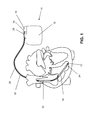
- FIG. 1 an implantable medical device in the form of an implantable cardiac stimulator 10 is shown, to which an electrode lead 20 having an elongated conductor is connected.
- the implantable cardiac stimulator 10 may be a pacemaker or a cardioverter / defibrillator (ICD).
- the heart stimulator 10 is a ventricular pacemaker and defibrillator.
- Other known cardiac stimulators are dual chamber pacemakers for stimulation of the right atrium and right ventricle, or biventricular pacemakers, which can also stimulate the left ventricle in addition to the right ventricle.
- Such stimulators typically have a housing 12, which is usually made of metal and thus is electrically conductive and can serve as a large electrode pole.
- a terminal housing 14 is typically attached, which is also referred to as a header.
- Such a header typically has contact sockets for receiving plug contacts.
- the contact sockets have electrical contacts 16, which are connected via corresponding conductors with an arranged in the housing 12 of the heart stimulator 10 electronics.
- the electrode line 20 represents an implantable medical device with an elongate, electrical function conductor. Electrode poles in the form of a tip or tip electrode 22 and a ring electrode 24 arranged in the vicinity thereof are arranged at a distal end of the electrode line 20 in a manner known per se arranged.
- the electrode poles 22 and 24 are designed such that, depending on the function of a cardiac stimulator to which the electrode lead 20 is connected, they serve to sense electrical potentials of the heart tissue (myocardium) or to emit electrical signals, for example to deliver stimulation pulses to the surrounding them Heart tissue, are formed.
- FIG. 1 shows how the electrode poles, so the tip electrode 22 and the ring electrode 24, in the application, the electrode line 20, located in the apex of a right ventricle of a heart.
- Both the tip electrode 22 and the ring electrode 24 are electrically connected via at least one electrical conductor 26 to a contact of a plug 28 at the proximal end of the electrode line 20.
- the plug 28 has electrical contacts which correspond to the electrical contacts 16 of the contact socket in the connection housing 14 of the implantable cardiac stimulator.
- the electrical conductors 26 in the electrode line 20 may be formed as approximately elongated cable conductor or as a helical coiled conductor. Such conductors electrically conductively connect functional electrode poles to electrical contacts of the plug contact at the proximal end of the electrode line 20 serve to transmit electrical signals from plug contact to the respective electrode pole or to guide sensed signals representing electrical potential from the respective electrode pole to the plug contact.
- the electrical conductors 26, which connect the electrode poles 22 and 24, respectively, to the electrical contacts of the plug 28 of the electrode line 20, are surrounded over most of their length by an insulating sheath, so that an electrical contact to the tissue of the heart is targeted via the electrode poles comes about.
- the electrode line 20 In addition to the electrode poles 22 and 24, which typically serve the (in this case, ventricular) stimulation of the heart tissue, the electrode line 20 also has two larger-area electrode poles 30 and 32, which serve as defibrillation electrodes and are formed by at least one bare helix-like coiled wire ,
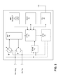
- FIG. 2 shows exemplary and schematically some components of the heart stimulator 10 from FIG. 1 .
- Typical components of such a heart stimulator are a control unit 40, one or more sensing units 42, which each represent a diagnostic unit and one or more stimulation units 44, which each represent a therapy unit.
- the control unit 40 is previously connected to the sensing unit 42 as well as to the stimulation unit 44.
- Both the sensing unit 42 and the stimulation unit 44 are each connected to electrode terminals in order to be able to detect electrical potentials of the heart tissue via the right ventricular ring electrode 24 and / or the right ventricular tip electrode 22 in the case of the sensing unit 42 or, for example, in the case of the stimulation unit 44 the right ventricular ring electrode 24 and / or the right ventricular tip electrode 22 to spend.
- control unit 40 is connected to a memory unit 46 for storing detected values of respective parameters to be measured.
- a telemetry unit 48 also connected to the control unit 40 makes it possible to transmit acquired values of parameters to an external device or to receive control commands from an external device.
- the control unit 40 is also connected to an MRI detection unit 50, which is designed to detect MRT-typical magnetic and / or electromagnetic alternating field and / or mechanical oscillations and to output an output signal to the control unit 40, which detects the presence of such MRT. indicates typical magnetic and / or electromagnetic alternating field and / or mechanical vibrations.
- the MRT detection unit 50 has a magnetic field sensor 52 and / or sensors for detecting alternating electromagnetic fields and / or sensors for detecting mechanical vibrations.
- the control unit 40 is also connected to a test unit in the form of an impedance determination unit 56.
- the impedance determination unit 56 is connected to a current source I and a voltage measuring unit U, which in turn are in turn connected to the terminals for the ring electrode 24 and the tip electrode 22.
- the DC power source I constantly emit current pulses via the tip electrode 22 and the ring electrode 24 and the voltage measuring unit U can thereby each falling Measure the voltage. From these values, the impedance determination unit 56 can determine a respective impedance value.
- an impedance value determined in this way depends on various factors. For example, a break of an electrical conductor in the electrode line 20 would manifest itself in a very high impedance value.
- the impedance to be measured between the electrode poles 22 and 24 also depends on the amount of blood in the right ventricle of a heart, so that the impedance to be measured varies cyclically in accordance with the cardiac cycle. For example, the impedance increases with decreasing blood volume, i. H. with decreasing volume of the right ventricle, so that a cyclic increase in impedance indicates the cyclic contraction of the right ventricle (right ventricle). Similarly, a corresponding increase in the measured impedance due to a chamber contraction after delivery of a stimulation pulse may indicate the stimulation success.
- the impedance determination unit 56 is capable of performing an automatic capture control (ACC).
- the measured impedance also depends on the impedance of the electrode-pole tissue contact. Therefore, by evaluating the measured impedance values, it is also possible to detect edema formation, as may occur, for example, as a result of heating of the electrode poles as a result of alternating magnetic fields of an MRI scanner.
- FIG. 4 is the desired MRI procedure for a patient with an electronic implant and thus the task is shown.
- the patient can undergo an MRI scan (220) without prior follow-up by the implant specialist, and the implant specialist (230) will automatically be notified of the exam, providing system integrity without having to examine the patient directly.
- the system integrity check should be opposite FIG. 3 additionally be improved by further automatic follow-up examinations.
- the operation of the heart stimulator 10 or other aspects of the invention described herein implements electronic implant is preferably as follows:
- an MRT environment is automatically detected by the electronic implant (with, for example, a sensor as in, for example, the copending patent application) US 12 / 970,290 described), triggered by a predetermined delay automatic pre-tests for detecting certain parameters such as stimulus threshold, electrode impedance, battery voltage, signal amplitudes, etc. triggered. Thereafter, the treating implant specialist is automatically informed via a central service center that his patient had an MRI examination and thus receives the data via remote data transmission - that is, the acquired values of the system integrity parameters - which he would have had to charge according to the current state of technology.
- the control unit 40 immediately starts a "pre-check of the patient" as usual according to current guidelines before an MRI examination.
- a pre-test eg, electrode data such as impedance, stimulus threshold, signal amplitudes etc. are automatically determined and evaluated by the implant. If this test is not passed, the implant makes itself felt with the MRI device - ie the MRI scanner - with resources such as in the parallel pending patent application US 12 / 972,452 are disclosed and the MRI procedure is aborted.
- the control unit 40 immediately triggers an MRT operating mode and thus an impedance monitoring for characterizing the electrode-tissue contact for a possible local edema formation determine, for example, the result of high heating or other irritation (by vibration, etc.) of the tissue may be.
- the control unit terminates the MRI mode of operation and thus the impedance monitoring after "MRI end detected” and sends the results via the telemetry unit 48 to a central service center. If a threshold for the detected impedance is exceeded, this is considered an indication of an edema.
- control unit causes the control unit to trigger a signal to the magnetic resonance tomograph and / or the control unit triggers mitigating measures, possibly at the expense of higher energy consumption.
- mitigating measures can be eg active procedures such as cooling by means of a Peltier element (which would then also be part of the medical device).
- the recorded values of the system integration parameters also run into the Holter for readability later or in the event that there is no radio link for wireless telemetry via the telemetry unit or if the respective patient is not connected to a central service center.
- An impedance measurement as part of the determination of values of the system integrity parameters takes place in a frequency range of more than 100 kHz except the bands +/- 5 MHz to the typical Larmor frequency for the respective MR scanner. This avoids mutual interference, i. the impedance measurement of the implant is not disturbed by the scan sequence, and conversely, the impedance measurement of the implant does not interfere with the imaging.
- impedance measurements in the frequency ranges 100kHz - 59MHz, 69MHz - 123MHz, 133MHz - 290MHz,> 300MHz are preferred.
- the stimulus threshold of cardiac tissue indicates what strength a stimulation pulse must exceed to cause a stimulated contraction of a respective heart chamber.
- stimulation pulses of varying intensity are typically indicated to the heart tissue, and then a stimulation success check is carried out in each case. Thus, it can be determined from which stimulation pulse strength a stimulation success occurs and thus where the stimulus threshold of the respective heart tissue lies.
- the implant cyclically performs system integrity parameter monitoring in a post-MRI mode of operation and compares these with parameters from the MRI scan and informs upon parameter drift after MRI scan the implant specialist via telemetric data transmission to the central service center.
- the control unit 40 After completion of an MRI scan detected by the MRI detection unit, the control unit 40 places the implant in an "automatic post-MRI mode with automatic data transmission", whereby the values to be transmitted in the post MRI mode are adjusted by comparing the measured values before and after of the MRI examination.
- the post MRI mode is terminated either when the control unit 40 and / or the central service detect a "normalization" of the measured values of the system integrity parameters, which are further monitored automatically by the implant, or by a remote programmer commanded by the implant specialist central service center is triggered.
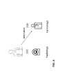
- FIG. 5 shows how an implant 10 is telemetrically connected to a central service center 310 via a patient device 300 serving as a body-external relay station.
- a patient device 300 serving as a body-external relay station.
- values received by the implant 10 can be evaluated and evaluated.
- the available computing capacity is higher in the service center than in the implant.
- values of an implant can be compared with values of other, similar or identical implants.
- a supervising physician (cardiologist) or an implant specialist 320 can also be informed via the central service center, which if necessary can act via central service center or directly on the implant 10 if, for example, deteriorated values of system integrity parameters occur as a result of an MRI exposure there is a corresponding need for action.
- MRI-typical and similar magnetic and / or electromagnetic alternating field and / or mechanical oscillations can also be applied to other currently contraindicated therapy and diagnostic methods, such as e.g. Therapeutic irradiation etc. are transmitted.
- the MRI recognition unit is to be replaced by another therapy recognition unit that is set aside from the respective diagnosis or therapy procedure.
- alternating fields of mechanical nature such as vibrations or acoustic signals are used, on the basis of which the presence or no longer existence an interference field is detected in order to switch the described functional modes of the implant oriented.
- the solution according to the invention offers the advantage that a considerable simplification of an MRI procedure is possible for patients with electronic implants, without restricting patient safety compared to the currently approved process.
Landscapes
- Health & Medical Sciences (AREA)
- Public Health (AREA)
- Life Sciences & Earth Sciences (AREA)
- Veterinary Medicine (AREA)
- General Health & Medical Sciences (AREA)
- Engineering & Computer Science (AREA)
- Biomedical Technology (AREA)
- Animal Behavior & Ethology (AREA)
- Radiology & Medical Imaging (AREA)
- Nuclear Medicine, Radiotherapy & Molecular Imaging (AREA)
- Heart & Thoracic Surgery (AREA)
- Cardiology (AREA)
- Electromagnetism (AREA)
- Physics & Mathematics (AREA)
- Electrotherapy Devices (AREA)
- Measuring And Recording Apparatus For Diagnosis (AREA)
Applications Claiming Priority (1)
| Application Number | Priority Date | Filing Date | Title |
|---|---|---|---|
| US201161466486P | 2011-03-23 | 2011-03-23 |
Publications (3)
| Publication Number | Publication Date |
|---|---|
| EP2502646A2 true EP2502646A2 (fr) | 2012-09-26 |
| EP2502646A3 EP2502646A3 (fr) | 2012-12-26 |
| EP2502646B1 EP2502646B1 (fr) | 2014-03-12 |
Family
ID=45887930
Family Applications (1)
| Application Number | Title | Priority Date | Filing Date |
|---|---|---|---|
| EP12159241.4A Active EP2502646B1 (fr) | 2011-03-23 | 2012-03-13 | Appareil implantable |
Country Status (2)
| Country | Link |
|---|---|
| US (1) | US8750963B2 (fr) |
| EP (1) | EP2502646B1 (fr) |
Families Citing this family (3)
| Publication number | Priority date | Publication date | Assignee | Title |
|---|---|---|---|---|
| WO2016142174A1 (fr) * | 2015-03-09 | 2016-09-15 | Koninklijke Philips N.V. | Procédé et module de sécurité pour détecter de façon automatique ou semi-automatique si un examen par résonance magnétique (rm) d'une personne est approuvé, avec un système de rm prédéterminé |
| WO2023111730A1 (fr) * | 2021-12-15 | 2023-06-22 | Medtronic, Inc. | Vérification secondaire d'une exposition par irm au niveau d'un dispositif médical implantable |
| WO2024104706A1 (fr) * | 2022-11-18 | 2024-05-23 | Biotronik Se & Co. Kg | Dispositif médical implantable ayant un mode de reconnaissance de chirurgie automatique |
Family Cites Families (12)
| Publication number | Priority date | Publication date | Assignee | Title |
|---|---|---|---|---|
| US5957861A (en) | 1997-01-31 | 1999-09-28 | Medtronic, Inc. | Impedance monitor for discerning edema through evaluation of respiratory rate |
| US20090163980A1 (en) | 2007-12-21 | 2009-06-25 | Greatbatch Ltd. | Switch for turning off therapy delivery of an active implantable medical device during mri scans |
| US7369898B1 (en) | 2004-12-22 | 2008-05-06 | Pacesetter, Inc. | System and method for responding to pulsed gradient magnetic fields using an implantable medical device |
| US8165693B2 (en) | 2005-07-21 | 2012-04-24 | Cyberonics, Inc. | Safe-mode implantable medical devices |
| EP2069010B1 (fr) * | 2006-09-25 | 2014-03-12 | St. Jude Medical AB | Système médical pour déterminer les paramètres d'un dispositif implantable |
| US8180438B2 (en) * | 2008-01-30 | 2012-05-15 | Greatbatch Ltd. | Minimally invasive physiologic parameter recorder and introducer system |
| US8160717B2 (en) | 2008-02-19 | 2012-04-17 | Cardiac Pacemakers, Inc. | Model reference identification and cancellation of magnetically-induced voltages in a gradient magnetic field |
| AU2009307979A1 (en) * | 2008-10-23 | 2010-04-29 | Cardiac Pacemakers, Inc. | Systems and methods to detect implantable medical device configuration changes affecting MRI conditional safety |
| US8150516B2 (en) * | 2008-12-11 | 2012-04-03 | Pacesetter, Inc. | Systems and methods for operating an implantable device for medical procedures |
| EP2338564B1 (fr) | 2009-12-22 | 2013-03-27 | BIOTRONIK CRM Patent AG | Optocoupleur IRM |
| EP2338563B1 (fr) | 2009-12-22 | 2013-11-20 | BIOTRONIK CRM Patent AG | Signalisation IRM |
| US9002450B2 (en) * | 2010-12-21 | 2015-04-07 | Pacesetter, Inc. | Systems and methods for assessing the sphericity and dimensional extent of heart chambers for use with an implantable medical device |
-
2012
- 2012-03-12 US US13/418,326 patent/US8750963B2/en active Active
- 2012-03-13 EP EP12159241.4A patent/EP2502646B1/fr active Active
Also Published As
| Publication number | Publication date |
|---|---|
| EP2502646B1 (fr) | 2014-03-12 |
| EP2502646A3 (fr) | 2012-12-26 |
| US8750963B2 (en) | 2014-06-10 |
| US20120245452A1 (en) | 2012-09-27 |
Similar Documents
| Publication | Publication Date | Title |
|---|---|---|
| US9014807B2 (en) | Lead fault detection for implantable medical device | |
| US9539428B2 (en) | Isolating lead conductor for fault detection | |
| US20120191153A1 (en) | Diagnosis of lead fracture and connection problems | |
| US7233825B2 (en) | Impedance measurement in implanted device | |
| US10039919B2 (en) | Methods and apparatus for detecting and localizing partial conductor failures of implantable device leads | |
| CN104334231B (zh) | 带有用于确定是否存在引线相关状况的装置的可植入医疗系统 | |
| EP3284516B1 (fr) | Implant et procédé d'identification d'une ligne d'électrodes | |
| US20190290155A1 (en) | Medical device and method for evaluating data for defects in an electrode lead | |
| EP3025759A1 (fr) | Appareil implantable actif adapté pour une utilisation avec irm | |
| EP2502646B1 (fr) | Appareil implantable | |
| CN104922794A (zh) | 一种测试刺激电极的位置评估装置 | |
| EP2578268B1 (fr) | Capteur de température pour un appareil médical implantable | |
| EP2478932B1 (fr) | Appareil implantable | |
| US20220266035A1 (en) | Short pulse width systems and methods for deep brain stimulation | |
| EP2468353B1 (fr) | Appareil implantable | |
| EP3025757B1 (fr) | Appareil actif implantable pour mrt | |
| EP2140910B1 (fr) | Stimulateur cardiaque destiné au traitement des rythmes tachycardiques | |
| CN204864539U (zh) | 一种测试刺激电极的位置评估装置 | |
| DE102008020123A1 (de) | Ventrikulärer Herzstimulator | |
| DE3722829C2 (de) | Verfahren und Anordnung zur Steuerung der Impulsabgabe eines implantierbaren elektromedizinischen Gerätes | |
| EP2174688B1 (fr) | Dispositif pour traitement des signaux du coeur | |
| US20230019319A1 (en) | Lead integrity evaluation based on impedance variability | |
| EP2915559B1 (fr) | Appareil implantable | |
| US8838241B1 (en) | Neurostimulation controlled by assessment of cardiovascular risk | |
| EP2075033A1 (fr) | Stimulateur cardiaque biventriculair |
Legal Events
| Date | Code | Title | Description |
|---|---|---|---|
| PUAI | Public reference made under article 153(3) epc to a published international application that has entered the european phase |
Free format text: ORIGINAL CODE: 0009012 |
|
| AK | Designated contracting states |
Kind code of ref document: A2 Designated state(s): AL AT BE BG CH CY CZ DE DK EE ES FI FR GB GR HR HU IE IS IT LI LT LU LV MC MK MT NL NO PL PT RO RS SE SI SK SM TR |
|
| AX | Request for extension of the european patent |
Extension state: BA ME |
|
| PUAL | Search report despatched |
Free format text: ORIGINAL CODE: 0009013 |
|
| AK | Designated contracting states |
Kind code of ref document: A3 Designated state(s): AL AT BE BG CH CY CZ DE DK EE ES FI FR GB GR HR HU IE IS IT LI LT LU LV MC MK MT NL NO PL PT RO RS SE SI SK SM TR |
|
| AX | Request for extension of the european patent |
Extension state: BA ME |
|
| RIC1 | Information provided on ipc code assigned before grant |
Ipc: A61N 1/37 20060101AFI20121121BHEP |
|
| 17P | Request for examination filed |
Effective date: 20130619 |
|
| RBV | Designated contracting states (corrected) |
Designated state(s): AL AT BE BG CH CY CZ DE DK EE ES FI FR GB GR HR HU IE IS IT LI LT LU LV MC MK MT NL NO PL PT RO RS SE SI SK SM TR |
|
| GRAP | Despatch of communication of intention to grant a patent |
Free format text: ORIGINAL CODE: EPIDOSNIGR1 |
|
| RIC1 | Information provided on ipc code assigned before grant |
Ipc: A61N 1/37 20060101AFI20130731BHEP Ipc: A61N 1/372 20060101ALN20130731BHEP |
|
| RIC1 | Information provided on ipc code assigned before grant |
Ipc: A61N 1/37 20060101AFI20130808BHEP Ipc: A61N 1/372 20060101ALN20130808BHEP |
|
| INTG | Intention to grant announced |
Effective date: 20130830 |
|
| GRAP | Despatch of communication of intention to grant a patent |
Free format text: ORIGINAL CODE: EPIDOSNIGR1 |
|
| INTG | Intention to grant announced |
Effective date: 20131219 |
|
| RIC1 | Information provided on ipc code assigned before grant |
Ipc: A61N 1/372 20060101ALN20131209BHEP Ipc: A61N 1/37 20060101AFI20131209BHEP |
|
| GRAS | Grant fee paid |
Free format text: ORIGINAL CODE: EPIDOSNIGR3 |
|
| GRAA | (expected) grant |
Free format text: ORIGINAL CODE: 0009210 |
|
| AK | Designated contracting states |
Kind code of ref document: B1 Designated state(s): AL AT BE BG CH CY CZ DE DK EE ES FI FR GB GR HR HU IE IS IT LI LT LU LV MC MK MT NL NO PL PT RO RS SE SI SK SM TR |
|
| REG | Reference to a national code |
Ref country code: GB Ref legal event code: FG4D Free format text: NOT ENGLISH |
|
| REG | Reference to a national code |
Ref country code: CH Ref legal event code: EP |
|
| REG | Reference to a national code |
Ref country code: AT Ref legal event code: REF Ref document number: 655827 Country of ref document: AT Kind code of ref document: T Effective date: 20140315 |
|
| REG | Reference to a national code |
Ref country code: IE Ref legal event code: FG4D Free format text: LANGUAGE OF EP DOCUMENT: GERMAN |
|
| REG | Reference to a national code |
Ref country code: DE Ref legal event code: R096 Ref document number: 502012000406 Country of ref document: DE Effective date: 20140424 |
|
| REG | Reference to a national code |
Ref country code: NL Ref legal event code: VDEP Effective date: 20140312 |
|
| PG25 | Lapsed in a contracting state [announced via postgrant information from national office to epo] |
Ref country code: NO Free format text: LAPSE BECAUSE OF FAILURE TO SUBMIT A TRANSLATION OF THE DESCRIPTION OR TO PAY THE FEE WITHIN THE PRESCRIBED TIME-LIMIT Effective date: 20140612 Ref country code: LT Free format text: LAPSE BECAUSE OF FAILURE TO SUBMIT A TRANSLATION OF THE DESCRIPTION OR TO PAY THE FEE WITHIN THE PRESCRIBED TIME-LIMIT Effective date: 20140312 |
|
| REG | Reference to a national code |
Ref country code: LT Ref legal event code: MG4D |
|
| PG25 | Lapsed in a contracting state [announced via postgrant information from national office to epo] |
Ref country code: SE Free format text: LAPSE BECAUSE OF FAILURE TO SUBMIT A TRANSLATION OF THE DESCRIPTION OR TO PAY THE FEE WITHIN THE PRESCRIBED TIME-LIMIT Effective date: 20140312 Ref country code: CY Free format text: LAPSE BECAUSE OF FAILURE TO SUBMIT A TRANSLATION OF THE DESCRIPTION OR TO PAY THE FEE WITHIN THE PRESCRIBED TIME-LIMIT Effective date: 20140312 Ref country code: FI Free format text: LAPSE BECAUSE OF FAILURE TO SUBMIT A TRANSLATION OF THE DESCRIPTION OR TO PAY THE FEE WITHIN THE PRESCRIBED TIME-LIMIT Effective date: 20140312 |
|
| PG25 | Lapsed in a contracting state [announced via postgrant information from national office to epo] |
Ref country code: RS Free format text: LAPSE BECAUSE OF FAILURE TO SUBMIT A TRANSLATION OF THE DESCRIPTION OR TO PAY THE FEE WITHIN THE PRESCRIBED TIME-LIMIT Effective date: 20140312 Ref country code: LV Free format text: LAPSE BECAUSE OF FAILURE TO SUBMIT A TRANSLATION OF THE DESCRIPTION OR TO PAY THE FEE WITHIN THE PRESCRIBED TIME-LIMIT Effective date: 20140312 Ref country code: HR Free format text: LAPSE BECAUSE OF FAILURE TO SUBMIT A TRANSLATION OF THE DESCRIPTION OR TO PAY THE FEE WITHIN THE PRESCRIBED TIME-LIMIT Effective date: 20140312 |
|
| PG25 | Lapsed in a contracting state [announced via postgrant information from national office to epo] |
Ref country code: NL Free format text: LAPSE BECAUSE OF FAILURE TO SUBMIT A TRANSLATION OF THE DESCRIPTION OR TO PAY THE FEE WITHIN THE PRESCRIBED TIME-LIMIT Effective date: 20140312 Ref country code: BG Free format text: LAPSE BECAUSE OF FAILURE TO SUBMIT A TRANSLATION OF THE DESCRIPTION OR TO PAY THE FEE WITHIN THE PRESCRIBED TIME-LIMIT Effective date: 20140612 Ref country code: IS Free format text: LAPSE BECAUSE OF FAILURE TO SUBMIT A TRANSLATION OF THE DESCRIPTION OR TO PAY THE FEE WITHIN THE PRESCRIBED TIME-LIMIT Effective date: 20140712 Ref country code: RO Free format text: LAPSE BECAUSE OF FAILURE TO SUBMIT A TRANSLATION OF THE DESCRIPTION OR TO PAY THE FEE WITHIN THE PRESCRIBED TIME-LIMIT Effective date: 20140312 Ref country code: CZ Free format text: LAPSE BECAUSE OF FAILURE TO SUBMIT A TRANSLATION OF THE DESCRIPTION OR TO PAY THE FEE WITHIN THE PRESCRIBED TIME-LIMIT Effective date: 20140312 Ref country code: EE Free format text: LAPSE BECAUSE OF FAILURE TO SUBMIT A TRANSLATION OF THE DESCRIPTION OR TO PAY THE FEE WITHIN THE PRESCRIBED TIME-LIMIT Effective date: 20140312 |
|
| PG25 | Lapsed in a contracting state [announced via postgrant information from national office to epo] |
Ref country code: ES Free format text: LAPSE BECAUSE OF FAILURE TO SUBMIT A TRANSLATION OF THE DESCRIPTION OR TO PAY THE FEE WITHIN THE PRESCRIBED TIME-LIMIT Effective date: 20140312 Ref country code: SK Free format text: LAPSE BECAUSE OF FAILURE TO SUBMIT A TRANSLATION OF THE DESCRIPTION OR TO PAY THE FEE WITHIN THE PRESCRIBED TIME-LIMIT Effective date: 20140312 Ref country code: PL Free format text: LAPSE BECAUSE OF FAILURE TO SUBMIT A TRANSLATION OF THE DESCRIPTION OR TO PAY THE FEE WITHIN THE PRESCRIBED TIME-LIMIT Effective date: 20140312 |
|
| REG | Reference to a national code |
Ref country code: DE Ref legal event code: R097 Ref document number: 502012000406 Country of ref document: DE |
|
| PG25 | Lapsed in a contracting state [announced via postgrant information from national office to epo] |
Ref country code: PT Free format text: LAPSE BECAUSE OF FAILURE TO SUBMIT A TRANSLATION OF THE DESCRIPTION OR TO PAY THE FEE WITHIN THE PRESCRIBED TIME-LIMIT Effective date: 20140714 |
|
| PLBE | No opposition filed within time limit |
Free format text: ORIGINAL CODE: 0009261 |
|
| STAA | Information on the status of an ep patent application or granted ep patent |
Free format text: STATUS: NO OPPOSITION FILED WITHIN TIME LIMIT |
|
| PG25 | Lapsed in a contracting state [announced via postgrant information from national office to epo] |
Ref country code: MC Free format text: LAPSE BECAUSE OF FAILURE TO SUBMIT A TRANSLATION OF THE DESCRIPTION OR TO PAY THE FEE WITHIN THE PRESCRIBED TIME-LIMIT Effective date: 20140312 Ref country code: DK Free format text: LAPSE BECAUSE OF FAILURE TO SUBMIT A TRANSLATION OF THE DESCRIPTION OR TO PAY THE FEE WITHIN THE PRESCRIBED TIME-LIMIT Effective date: 20140312 |
|
| 26N | No opposition filed |
Effective date: 20141215 |
|
| PG25 | Lapsed in a contracting state [announced via postgrant information from national office to epo] |
Ref country code: RS Free format text: LAPSE BECAUSE OF FAILURE TO SUBMIT A TRANSLATION OF THE DESCRIPTION OR TO PAY THE FEE WITHIN THE PRESCRIBED TIME-LIMIT Effective date: 20140903 |
|
| REG | Reference to a national code |
Ref country code: FR Ref legal event code: ST Effective date: 20150213 |
|
| REG | Reference to a national code |
Ref country code: DE Ref legal event code: R097 Ref document number: 502012000406 Country of ref document: DE Effective date: 20141215 |
|
| PG25 | Lapsed in a contracting state [announced via postgrant information from national office to epo] |
Ref country code: IT Free format text: LAPSE BECAUSE OF FAILURE TO SUBMIT A TRANSLATION OF THE DESCRIPTION OR TO PAY THE FEE WITHIN THE PRESCRIBED TIME-LIMIT Effective date: 20140312 |
|
| PG25 | Lapsed in a contracting state [announced via postgrant information from national office to epo] |
Ref country code: FR Free format text: LAPSE BECAUSE OF NON-PAYMENT OF DUE FEES Effective date: 20140512 |
|
| REG | Reference to a national code |
Ref country code: DE Ref legal event code: R082 Ref document number: 502012000406 Country of ref document: DE Representative=s name: RANDOLL, SOEREN, DIPL.-CHEM. UNIV. DR. RER. NA, DE |
|
| PG25 | Lapsed in a contracting state [announced via postgrant information from national office to epo] |
Ref country code: SI Free format text: LAPSE BECAUSE OF FAILURE TO SUBMIT A TRANSLATION OF THE DESCRIPTION OR TO PAY THE FEE WITHIN THE PRESCRIBED TIME-LIMIT Effective date: 20140312 |
|
| PG25 | Lapsed in a contracting state [announced via postgrant information from national office to epo] |
Ref country code: MT Free format text: LAPSE BECAUSE OF FAILURE TO SUBMIT A TRANSLATION OF THE DESCRIPTION OR TO PAY THE FEE WITHIN THE PRESCRIBED TIME-LIMIT Effective date: 20140312 |
|
| PG25 | Lapsed in a contracting state [announced via postgrant information from national office to epo] |
Ref country code: SM Free format text: LAPSE BECAUSE OF FAILURE TO SUBMIT A TRANSLATION OF THE DESCRIPTION OR TO PAY THE FEE WITHIN THE PRESCRIBED TIME-LIMIT Effective date: 20140312 |
|
| PG25 | Lapsed in a contracting state [announced via postgrant information from national office to epo] |
Ref country code: GR Free format text: LAPSE BECAUSE OF FAILURE TO SUBMIT A TRANSLATION OF THE DESCRIPTION OR TO PAY THE FEE WITHIN THE PRESCRIBED TIME-LIMIT Effective date: 20140613 |
|
| PG25 | Lapsed in a contracting state [announced via postgrant information from national office to epo] |
Ref country code: LU Free format text: LAPSE BECAUSE OF NON-PAYMENT OF DUE FEES Effective date: 20140313 Ref country code: HU Free format text: LAPSE BECAUSE OF FAILURE TO SUBMIT A TRANSLATION OF THE DESCRIPTION OR TO PAY THE FEE WITHIN THE PRESCRIBED TIME-LIMIT; INVALID AB INITIO Effective date: 20120313 Ref country code: TR Free format text: LAPSE BECAUSE OF FAILURE TO SUBMIT A TRANSLATION OF THE DESCRIPTION OR TO PAY THE FEE WITHIN THE PRESCRIBED TIME-LIMIT Effective date: 20140312 Ref country code: BE Free format text: LAPSE BECAUSE OF FAILURE TO SUBMIT A TRANSLATION OF THE DESCRIPTION OR TO PAY THE FEE WITHIN THE PRESCRIBED TIME-LIMIT Effective date: 20140331 |
|
| GBPC | Gb: european patent ceased through non-payment of renewal fee |
Effective date: 20160313 |
|
| PG25 | Lapsed in a contracting state [announced via postgrant information from national office to epo] |
Ref country code: GB Free format text: LAPSE BECAUSE OF NON-PAYMENT OF DUE FEES Effective date: 20160313 |
|
| REG | Reference to a national code |
Ref country code: AT Ref legal event code: MM01 Ref document number: 655827 Country of ref document: AT Kind code of ref document: T Effective date: 20170313 |
|
| PG25 | Lapsed in a contracting state [announced via postgrant information from national office to epo] |
Ref country code: MK Free format text: LAPSE BECAUSE OF FAILURE TO SUBMIT A TRANSLATION OF THE DESCRIPTION OR TO PAY THE FEE WITHIN THE PRESCRIBED TIME-LIMIT Effective date: 20140312 |
|
| PG25 | Lapsed in a contracting state [announced via postgrant information from national office to epo] |
Ref country code: AT Free format text: LAPSE BECAUSE OF NON-PAYMENT OF DUE FEES Effective date: 20170313 |
|
| PG25 | Lapsed in a contracting state [announced via postgrant information from national office to epo] |
Ref country code: AL Free format text: LAPSE BECAUSE OF FAILURE TO SUBMIT A TRANSLATION OF THE DESCRIPTION OR TO PAY THE FEE WITHIN THE PRESCRIBED TIME-LIMIT Effective date: 20140312 |
|
| P01 | Opt-out of the competence of the unified patent court (upc) registered |
Effective date: 20230607 |
|
| PGFP | Annual fee paid to national office [announced via postgrant information from national office to epo] |
Ref country code: CH Payment date: 20230402 Year of fee payment: 12 |
|
| PGFP | Annual fee paid to national office [announced via postgrant information from national office to epo] |
Ref country code: IE Payment date: 20240319 Year of fee payment: 13 |
|
| PGFP | Annual fee paid to national office [announced via postgrant information from national office to epo] |
Ref country code: DE Payment date: 20240321 Year of fee payment: 13 |