EP2338566B1 - Implantable medical device with means for reconstructing an imperfectly sensed signal - Google Patents
Implantable medical device with means for reconstructing an imperfectly sensed signal Download PDFInfo
- Publication number
- EP2338566B1 EP2338566B1 EP10192894.3A EP10192894A EP2338566B1 EP 2338566 B1 EP2338566 B1 EP 2338566B1 EP 10192894 A EP10192894 A EP 10192894A EP 2338566 B1 EP2338566 B1 EP 2338566B1
- Authority
- EP
- European Patent Office
- Prior art keywords
- electromagnetic interference
- imd
- control unit
- detected
- detection
- Prior art date
- Legal status (The legal status is an assumption and is not a legal conclusion. Google has not performed a legal analysis and makes no representation as to the accuracy of the status listed.)
- Active
Links
Images


Classifications
-
- A—HUMAN NECESSITIES
- A61—MEDICAL OR VETERINARY SCIENCE; HYGIENE
- A61N—ELECTROTHERAPY; MAGNETOTHERAPY; RADIATION THERAPY; ULTRASOUND THERAPY
- A61N1/00—Electrotherapy; Circuits therefor
- A61N1/18—Applying electric currents by contact electrodes
- A61N1/32—Applying electric currents by contact electrodes alternating or intermittent currents
- A61N1/36—Applying electric currents by contact electrodes alternating or intermittent currents for stimulation
- A61N1/362—Heart stimulators
- A61N1/37—Monitoring; Protecting
- A61N1/3718—Monitoring of or protection against external electromagnetic fields or currents
Definitions
- the invention relates to a device and a method for dealing with electromagnetic fields, especially those fields that occur in imaging magnetic resonance imaging (hereinafter MRI or MRI) devices.
- MRI imaging magnetic resonance imaging
- MRI examinations are becoming increasingly important in diagnostic medicine, some patients are contraindicated for MRI examinations.
- a contraindication can be given by an at least partially implanted medical device (hereinafter also called an implant or IMD).
- IMD implanted medical device
- other technical applications also pose a danger to users of medical devices or implantable medical devices, especially if they generate strong electromagnetic interference fields (EMI, Electro Magnetic Interference) in your environment.
- EMI Electro Magnetic Interference
- US 20060293591 A1 describes an implantable medical device with a telemetry antenna and a lead with an elongated body comprising a conductor which extends from a proximal connection to a distal electrode.
- US 20040263172 A1 describes a voltage compensation unit which reduces effects caused by induced voltages on a device with a single conductor.
- IMD implantable medical device
- the at least partially implanted medical device included at least one unit for the detection of electromagnetic interference, at least including a sensor or indicator for electromagnetic interference fields and at least one Timepiece, at least one control unit that can be connected to the unit for detecting electromagnetic interference, at least one electrode line that is connected to the control unit and that has an electrode at the other end that is in contact with body tissue and that the electrode is either ins Extends inside the body or is located on the surface of an implant, the control unit only permitting the delivery of electrical stimulation pulses via the at least one electrode in time windows in which no electromagnetic interference is detected and / or the control unit reconstructing electrical signals detected via the at least one electrode Performs measurements for the time window in which electromagnetic interference is detected.
- IMD included at least one unit for the detection of electromagnetic interference, at least including a sensor or indicator for electromagnetic interference fields and at least one Timepiece, at least one control unit that can be connected to the unit for detecting electromagnetic interference, at least one electrode line that is connected to the control unit and that has an electrode at the other end that is in contact with body tissue and that
- the term at least partially implanted includes both fully implanted systems and those in which only components, for example, but not limited to, electrodes, including parts of the electrode lines and / or optical conductors, with sensors and / or actuators and / or stimulators, and / or lines from internal or external medication pumps and / or liquid pumps for diagnosis and / or therapy.
- the liquid pumps can be suitable for conveying liquids from the inside of the body to an analysis unit and / or therapy unit, which can be located both inside and outside the body.
- the at least partially implantable medical device is an external pacemaker and / or external defibrillator or implanted pacemaker and / or defibrillator / cardioverter and / or a cardiac resynchronization therapy device (CRT), a cardiac support system, such as a cardiac support pump, an artificial heart, a neurostimulator , an implanted monitoring device (patient monitor), an implanted medication pump, an implanted fluid pump, and / or an external heart-lung system, and that the control unit of the IMD determines the operating state of the IMD on the basis of the detected electromagnetic interference and / or of the at least one an electrode detects measured values and / or reconstructed measured values from predeterminable operating states.
- CTR cardiac resynchronization therapy device
- the timepiece has a memory that is designed to store time differences, such as therapy intervals and / or intervals of intrinsic system events.
- Therapy intervals are understood to mean the intervals at which therapies are delivered, both individual therapies and groups of therapies being included. Therapy intervals are, for example, but not limited to, RR or QT or TQ time or a corresponding parameter tuple from an IEGM.
- Various intervals are also possible with the intervals of intrinsic system events, such as, but not limited to, individual system events and / or groups of system events, such as QRS or other complexes or complete cardiac cycles and / or pathological events.
- IEGM is generally understood by those skilled in the art to be an intracardiac electrocardiogram.
- the time interval between two electrical stimuli is a therapy interval and that at least the previous therapy interval can be stored.
- the memory is organized as a "first in first out” (fifo).
- control unit uses the data from the timer to calculate the time of the next therapy.
- the calculation of the next therapy point in time is based on a cardiac rhythm estimate and / or a cardiac simulator.
- Parameters for the models for calculating the therapy times are programmable and / or the models for calculating the therapy times use the IEGM and / or EKG and / or reconstructed IEGM measurements for the calculation, ECG data being determined via external aids and at least partially implanted medical device are made available and also data from the patient history from the available information sources, such as, but not limited to, patient files, patient databases and / or patient device, and / or the calculation is based on the parameters and measurements stored in the implant a long-term storage and / or the calculation is based on the parameters and measurements stored in the implant, during the recording of which no electromagnetic interference has been detected.
- the calculation is based on an approximation model of the cardiac restitution and / or a linear or non-linear time series model and / or on a weighted mean of n previous time differences, with n greater than or equal to 1.
- Cardiac restitution is understood by the person skilled in the art to mean the relationship between the action potential duration of cardiac muscle cells as a function of the duration of the preceding diastolic interval - also known graphically as the restitution curve.
- the restitution curve can be used to estimate the repolarization time of the next cardiac cycle, thus avoiding stimulation into the vulnerable phase.
- the restitution curve can also be specified in a modified form depending on the previous RR intervals. In the simplest case, the curve only shows the static relationship between heart rate and repolarization behavior. A model approach with a higher level of detail also takes the dynamic relationships into account.
- the repolarization time also depends on the further past of the cardiac activity (e.g.
- the vulnerable phases of the cardiac excitation cycle are avoided when calculating the next therapy time and / or parameters for the models for calculating the therapy times are programmable and / or the models for calculating the therapy times include the IEGM and / or EKG and / or use reconstructed IEGM measurements for the calculation, whereby ECG data are determined via external aids and made available to the at least partially implanted medical device and also data from the patient history from the available information sources are included, such as patient files, patient databases, and / or Patient device, and / or the calculation is based on the parameters and measurements stored in the implant, specifically from a long-term memory and / or the calculation is based on the parameters and measurements stored in the implant, and no electromagnetic interference is detected when they are recorded have been recognized.
- This version is particularly relevant in connection with the so-called home monitoring, in which data from an implant are sent to a central location at predeterminable intervals and are made available from there or directly to a doctor.
- This exemplary embodiment can ensure that only valid data are forwarded to the patient database or the doctor.
- the stimulation unit is triggerable and / or retriggerable, especially by measurements in time windows without detected electromagnetic interference fields and / or by reconstructed measurement data between the time windows without detected electromagnetic interference fields, and / or the control unit suppresses the stimulation output or triggers a sub-threshold or zero-intensity stimulation output if an intrinsic event was detected by the detection unit of the control unit and / or was identified by the reconstruction of detection gaps.
- Sub-threshold intensity means stimulation pulses which lie below a predeterminable and / or presettable stimulation threshold, while the zero-intensity stimulations are carried out with a non-existent intensity or are only triggered.
- control unit has a priority circuit that temporarily allows therapy even in time windows in which electromagnetic interference have been detected by the unit for the detection of electromagnetic interference, the priority circuit being always activatable and / or only being activatable if an electromagnetic disturbance has been detected by the unit for the detection of electromagnetic interference and the disturbance has been measured under at least one predeterminable sensor value and / or at least one predeterminable indicator value.
- predeterminable should also be understood to mean that one of a plurality of predetermined sensor measured values and / or predetermined indicator values are used as a function of the patient's condition.
- the reconstruction of the measurement data between the time windows without a detected electromagnetic disturbance has at least one of the following properties
- the detection unit additionally has a blanking unit which hides overshoots in detected measurement signals, the blanking unit reflecting the relaxation behavior of the system, such as the electrode system and Input circuit, and / or the nature of the disturbance, such as high-frequency disturbances such as from RF fields, low-frequency disturbances, such as from gradient fields, are taken into account for the reconstruction, depending on the length of the disturbance, a reconstruction method is automatically selected, such as linear or polynomial interpolation, whereby the derivations at the connection points to the measured values are constant, for short interference lengths and pattern recognition of typical measurement curves, such as QRS complexes and / or T-waves and / or p-waves and / or combinations such as QRS-T section un d / or TP section and / or P-QRS section, a pattern recognition is used for the reconstruction, which recognizes typical measurement curves and forwards the recognized
- the IMD is switched to an operating state that is independent of a signal detection if no signal reconstruction from the detected signals is possible, which among other things, but not limited to, in the case of short time windows without electromagnetic interference in combination with at least medium-long periods electromagnetic interference occurs.
- At least one of the following measures is initiated when electromagnetic interference is detected, changing to an MRI-safe state, prolonged remaining in an MRI-safe state or insensitive to electromagnetic interference fields, and the delivery of electromagnetic pulses
- a medical device especially an implant
- the electromagnetic field especially for signaling to an MRI device, with the possibility of transmitting information in addition to the fault in this way and making it visible on the MRI screen.
- the unit for the detection of electromagnetic interference for the detection of electromagnetic fields comprises at least one of the following sensors or indicators, GMR sensor, MagFET sensor, Hall sensor, electro-optical converter as an indicator, the monitoring of battery voltages during capacitor charging processes as an indicator, the detection of RF fields as an indicator, the detection of magnetic gradient fields as an indicator, the detection of currents induced by electromagnetic fields as an indicator, the detection of specific vibrations or components designed as sensors for the detection of vibrations induced by Lorentz forces as an indicator.
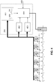
- Figure 1 describes the prior art in which the ICD patient (100) is followed up by a cardiologist before the planned MRI examination and the ICD is switched off (110).
- the MRI examination is performed by a radiologist with a delay of hours to days (120).
- the patient is looked after again by the cardiologist (130) and the ICD is switched on again.
- the patient is without the protection of the implanted defibrillator and largely without rhythm monitoring. This residual risk, measured by the benefits of the MRI scan, is currently accepted.
- the Figure 2 shows a possible interpretation matrix for possible reactions for different ratios of fault gap length and fault length, the fault gap length denoting the periods without disturbances and the disturbance length the length of the occurring and / or perceived electromagnetic interference.
- the type of detection of the electromagnetic interference is not important for the adapted IEGM scanning, in principle all technologies suitable for the detection of electromagnetic interference are possible, particularly but not limited to these, GMR sensors, MagFET sensors, Hall sensors, electro-optical ones Transducers, the monitoring of battery voltages during capacitor charging processes, the detection of RF fields, the detection of magnetic gradient fields, the detection of currents induced by electromagnetic fields, the detection of specific vibrations or components designed as sensors for the detection of vibrations induced by Lorentz forces.
- the matrix indicates, by way of example, the ratios of the gap length to the fault length which are reconstructed, interpolated and / or the original signal is used.
- the Figure 3 shows an exemplary reconstruction of the original signal 210 during the interference.
- the original signal 210 is overlaid by a disturbance 220 in the upper representation, which creates a blanking window 230, that is to say a window in which no signals can be detected that extend beyond the duration of the disturbance 220.
- the blanking window 240 the signal is reconstructed by interpolation, so that a reconstructed section 240 is created.
- the measured original signal 210 is forwarded to a heart simulator 250, and the gap that arises during the blanking window 230 due to the disturbance 220 in the original signal 210 is filled by the heart simulator 250 with the reconstruction 240.
- the reconstruction is an estimate of the T pattern.
- Metric extractors 400 measure continuously or by a trigger such as B. triggered by the interference field detector via signal 405 cardiac cycles with regard to RR intervals, RT intervals, QRS amplitude, width, area, T wave amplitude, width, area, and morphologies, but not limited to these.
- This is input information for the heart simulator 250, in one according to the invention particularly preferred implementation consisting of a morphology database 401, an RR predictor 402 and RT predictor 403.
- the next following RR and RT interval is estimated so that these are immediately available in the event of an upcoming fault.
- the database also prepares the morphologies based on the input information (as normalized curves for e.g. QRS or T-wave reconstruction), which has followed this pattern in the past (in the sense of the highest probability) with a similar previous morphology sequence. This pattern is then scaled and positioned with the results of the RR and RT predictors. Reconstructor 404 realizes this.
- FIG. 5 explains the RT predictor.
- Each RT interval corresponding to the depth of memory is plotted as the ordinate over the previous RR interval as the abscissa.
- the currently valid restitution curve is fitted (e.g. method of least squares). This enables the RT interval of the next cardiac cycle to be determined.
- This process can be implemented as a sliding window or in blocks.
- the RR predictor (not shown) can e.g. B. be implemented as a time series model with the following calculation rule.
- an expanded implementation In addition to RR intervals, an expanded implementation also takes into account RT intervals, QRS amplitude, width, area, T-wave amplitude, width, area, and morphologies (e.g. morphology classes and / or indices such as e.g. defined in the US 2006 / 0047216A1 , but not limited to this). Another expanded implementation also provides for non-linear links between the input information.
- the reconstructor selects the morphology of the signal section to be estimated (e.g. QRS complex or T-wave, etc.) from the database and scales and positions it on the time axis in the missing signal section according to the estimated RT and RR interval values.
- the amplitude scaling takes place on the basis of proportionality which is learned from past signal sections were. So z.
- the amplitude of the reconstructed T-wave is scaled as a percentage of the previous R wave, possibly also taking into account mean values from previous R waves and previous T wave amplitudes.
- the next QRS is first estimated.
- the RT predictor uses this RR interval to estimate the next RT time.
- this continues as in cases g and h.
- this is fixed frequency stimulation, e.g. B. D00, V00 or A00 mode.
- a security stimulus 701 is therefore provided after the watchdog counter 702 has expired. Taking the RR and RT predictors into account, the position of the vulnerable phase into which stimulation should not be used is estimated, as this could otherwise trigger an arrhythmia. Therefore, after the watchdog counter has elapsed, the delivery of this stimulus may be further delayed by a safety distance 703 ( Fig. 7 ).
Description
Die Erfindung bezieht sich auf eine Vorrichtung und ein Verfahren zum Umgang mit elektromagnetischen Feldern, speziell solchen Feldern, wie sie bei bildgebenden Kernspintomographie- (im folgenden MRT- oder MRI-) Geräten auftreten.The invention relates to a device and a method for dealing with electromagnetic fields, especially those fields that occur in imaging magnetic resonance imaging (hereinafter MRI or MRI) devices.
Obwohl MRI-Untersuchungen einen immer höheren Stellenwert in der diagnostischen Medizin erhalten, ist ein Teil der Patienten für MRI-Untersuchungen kontraindiziert. Eine solche Kontraindizierung kann durch ein mindestens teilweise implantiertes medizinisches Gerät (im Folgenden auch Implantat oder IMD) gegeben sein. Neben den MRI-Untersuchungen stellen aber auch andere technische Anwendungen eine Gefahr für die Nutzer von medizinischen Geräten oder implantierbaren medizinischen Geräten dar, besonders, wenn diese starke elektromagnetische Störfelder (EMI, Electro Magnetic Interference) in Ihrer Umgebung erzeugen.Although MRI examinations are becoming increasingly important in diagnostic medicine, some patients are contraindicated for MRI examinations. Such a contraindication can be given by an at least partially implanted medical device (hereinafter also called an implant or IMD). In addition to MRI examinations, other technical applications also pose a danger to users of medical devices or implantable medical devices, especially if they generate strong electromagnetic interference fields (EMI, Electro Magnetic Interference) in your environment.
Um MRI-Untersuchungen dennoch zu ermöglichen, sind verschiedene Ansätze, die sich entweder auf die Durchführung der MRI-Untersuchung oder auf das implantierbare medizinische Gerät beziehen, bekannt.In order to enable MRI examinations nevertheless, various approaches are known which relate either to the execution of the MRI examination or to the implantable medical device.
Unter anderem sind Technologien zur Erkennung von Magnetfeldern bekannt, die auf herkömmlichen Verfahren zur Magnetfelddetektion beruhen. So beschreibt die
Auch ist aus dem Stand der Technik die Schrift
Daher ist es Aufgabe der Erfindung, die Mängel im Stand der Technik zu beheben und ein Gerät bereitzustellen, das eine hohe Zuverlässigkeit unter elektromagnetischen Störungen (EMI, Electro Magnetic Interference) ermöglicht.It is therefore an object of the invention to remedy the shortcomings in the prior art and to provide a device which enables high reliability under electromagnetic interference (EMI, Electro Magnetic Interference).
Die Aufgabe wird durch ein zumindest teilweise implantierbares medizinisches Gerät (IMD) mit den Merkmalen des Anspruchs 1 gelöst.The object is achieved by an at least partially implantable medical device (IMD) with the features of
Dabei beinhaltete das zumindest teilweise implantierte medizinisches Gerät (IMD) mindestens eine Einheit zur Erkennung von elektromagnetischen Störungen, mindestens beinhaltend einen Sensor oder Indikator für elektromagnetische Störfelder und mindestens einen Zeitmesser, mindestens eine Steuereinheit, die mit der Einheit zur Erkennung von elektromagnetischen Störungen verbindbar ist, mindestens eine Elektrodenleitung, die mit der Steuereinheit verbunden ist und die am anderen Ende eine Elektrode aufweist, die im Kontakt mit Körpergewebe ist und wobei die Elektrode sich entweder ins Körperinnere erstreckt oder auf der Oberfläche eines Implantates befindet, wobei die Steuereinheit die Abgabe von elektrischen Stimulationsimpulsen über die mindestens eine Elektrode nur in Zeitfenstern erlaubt, in denen keine elektromagnetischen Störungen erkannt werden und/oder die Steuereinheit eine Rekonstruktion von über die mindestens eine Elektrode erfassten elektrischen Messungen für die Zeitfenster durchführt, in denen elektromagnetische Störungen erkannt werden.The at least partially implanted medical device (IMD) included at least one unit for the detection of electromagnetic interference, at least including a sensor or indicator for electromagnetic interference fields and at least one Timepiece, at least one control unit that can be connected to the unit for detecting electromagnetic interference, at least one electrode line that is connected to the control unit and that has an electrode at the other end that is in contact with body tissue and that the electrode is either ins Extends inside the body or is located on the surface of an implant, the control unit only permitting the delivery of electrical stimulation pulses via the at least one electrode in time windows in which no electromagnetic interference is detected and / or the control unit reconstructing electrical signals detected via the at least one electrode Performs measurements for the time window in which electromagnetic interference is detected.
Unter die Begrifflichkeit mindestens teilweise implantiert fallen dabei sowohl vollständig implantierte Systeme, als auch solche, bei denen nur Komponenten, zum Beispiel, aber nicht beschränkt auf, Elektroden, inklusive Teile der Elektrodenleitungen und/oder optische Leiter, mit Sensoren und/oder Aktuatoren und/oder Stimulatoren, und/oder Leitungen von internen oder externen Medikamentenpumpen und/oder Flüssigkeitspumpen zur Diagnose und/oder Therapie.
Die Flüssigkeitspumpen können einerseits geeignet sein, Flüssigkeiten aus dem Körperinneren zu einer Analyseeinheit und/oder Therapieeinheit zu befördern, die sich sowohl innerhalb, als auch außerhalb des Körpers befinden kann.The term at least partially implanted includes both fully implanted systems and those in which only components, for example, but not limited to, electrodes, including parts of the electrode lines and / or optical conductors, with sensors and / or actuators and / or stimulators, and / or lines from internal or external medication pumps and / or liquid pumps for diagnosis and / or therapy.
On the one hand, the liquid pumps can be suitable for conveying liquids from the inside of the body to an analysis unit and / or therapy unit, which can be located both inside and outside the body.
Bevorzugt wird, dass das zumindest teilweise implantierbare medizinische Gerät ein externer Herzschrittmacher und/oder externer Defibrillator oder implantierter Herzschrittmacher und/oder Defibrillator/Cardioverter und/oder ein kardiales Resynchronisationstherapiegerät (CRT), ein Herzunterstützungssystem, wie eine Herzunterstützungspumpe, ein künstliches Herz, ein Neurostimulator, ein implantiertes Überwachungsgerät (Patientenmonitor), eine implantierte Medikamentenpumpe, eine implantierte Flüssigkeitspumpe, und/oder ein externes Herz-Lungen-System ist, und dass die Steuereinheit des IMD den Betriebszustand des IMD anhand der detektierten elektromagnetischen Störung und/oder von mit der mindestens einen Elektrode detektierten Messwerten und/oder von rekonstruierten Messwerten aus vorbestimmbaren Betriebszuständen auswählt.It is preferred that the at least partially implantable medical device is an external pacemaker and / or external defibrillator or implanted pacemaker and / or defibrillator / cardioverter and / or a cardiac resynchronization therapy device (CRT), a cardiac support system, such as a cardiac support pump, an artificial heart, a neurostimulator , an implanted monitoring device (patient monitor), an implanted medication pump, an implanted fluid pump, and / or an external heart-lung system, and that the control unit of the IMD determines the operating state of the IMD on the basis of the detected electromagnetic interference and / or of the at least one an electrode detects measured values and / or reconstructed measured values from predeterminable operating states.
Auch wird bevorzugt, dass der Zeitmesser einen Speicher aufweist, der ausgelegt ist, Zeitdifferenzen, wie Therapieintervalle und/oder Intervalle von intrinsischen Systemereignissen, zu speichern. Unter Therapieintervallen sind dabei die Intervalle zu verstehen, in denen Therapien abgegeben werden, wobei sowohl einzelne Therapien, als auch Gruppen von Therapien umfasst sind. Therapieintervall sind beispielsweise, aber nicht beschränkt auf, RR- oder QT- oder TQ-Zeit oder ein entsprechendes Parametertupel aus einem IEGM. Auch bei den Intervallen von intrinsischen Systemereignissen sind verschiedene Intervalle möglich, wie, aber nicht beschränkt auf einzelne Systemereignisse und/oder Gruppen von Systemereignissen, wie QRS- oder andere Komplexe oder komplette Herzzyklen und/oder krankhafte Ereignisse. Unter IEGM versteht der Fachmann im Allgemeinen ein intrakardiales Elektrokardiogramm.It is also preferred that the timepiece has a memory that is designed to store time differences, such as therapy intervals and / or intervals of intrinsic system events. Therapy intervals are understood to mean the intervals at which therapies are delivered, both individual therapies and groups of therapies being included. Therapy intervals are, for example, but not limited to, RR or QT or TQ time or a corresponding parameter tuple from an IEGM. Various intervals are also possible with the intervals of intrinsic system events, such as, but not limited to, individual system events and / or groups of system events, such as QRS or other complexes or complete cardiac cycles and / or pathological events. IEGM is generally understood by those skilled in the art to be an intracardiac electrocardiogram.
Besonders bevorzugt wird, dass der zeitliche Abstand zwischen zwei elektrischen Stimuli ein Therapieintervall ist und dass zumindest das jeweils vorhergehende Therapieintervall speicherbar ist.It is particularly preferred that the time interval between two electrical stimuli is a therapy interval and that at least the previous therapy interval can be stored.
Auch wird besonders bevorzugt, dass der Speicher als "first in first out" (fifo) organisiert ist.It is also particularly preferred that the memory is organized as a "first in first out" (fifo).
Bevorzugt wird auch, dass die Steuereinheit mit den Daten des Zeitmessers den Zeitpunkt der nächsten Therapie berechnet.It is also preferred that the control unit uses the data from the timer to calculate the time of the next therapy.
Besonders bevorzugt wird, dass die Berechnung des nächsten Therapiezeitpunktes auf einer Herzrhythmusschätzung und/oder einem Herzsimulator beruht.
Parameter für die Modelle der Berechnung der Therapiezeitpunkte sind programmierbar und/oder die Modelle zur Berechnung der Therapiezeitpunkte die IEGM- und/oder EKG- und/oder rekonstruierten IEGM Messungen zur Berechnung heranziehen, wobei EKG-Daten über externe Hilfsmittel ermittelt werden und dem zumindest teilweise implantierten medizinischen Gerät zur Verfügung gestellt werden und auch Daten aus der Patientenhistorie aus den vorhanden Informationsquellen, wie, aber nicht darauf beschränkt, Patientenakten, Patientendatenbanken und/oder Patientengerät, und/oder die Berechnung auf den im Implantat gespeicherten Parameter und Messungen beruht, speziell aus einem Langzeitspeicher und/oder die Berechnung auf den im Implantat gespeicherten Parameter und Messungen beruht, bei deren Aufnahme keine elektromagnetischen Störungen detektiert worden sind.It is particularly preferred that the calculation of the next therapy point in time is based on a cardiac rhythm estimate and / or a cardiac simulator.
Parameters for the models for calculating the therapy times are programmable and / or the models for calculating the therapy times use the IEGM and / or EKG and / or reconstructed IEGM measurements for the calculation, ECG data being determined via external aids and at least partially implanted medical device are made available and also data from the patient history from the available information sources, such as, but not limited to, patient files, patient databases and / or patient device, and / or the calculation is based on the parameters and measurements stored in the implant a long-term storage and / or the calculation is based on the parameters and measurements stored in the implant, during the recording of which no electromagnetic interference has been detected.
Auch wird besonders bevorzugt, dass die Berechnung auf einem Approximationsmodell der kardialen Restitution und/oder einem linearen oder nicht linearen Zeitreihenmodell und/oder auf einem gewichteten Mittel von n vorangegangenen Zeitdifferenzen, mit n größer oder gleich 1, beruht.It is also particularly preferred that the calculation is based on an approximation model of the cardiac restitution and / or a linear or non-linear time series model and / or on a weighted mean of n previous time differences, with n greater than or equal to 1.
Unter kardialer Restitution versteht der Fachmann den Zusammenhang zwischen der Aktionspotentialdauer von Herzmuskelzellen in Abhängigkeit der Dauer des vorangegangenen diastolischen Intervalls - graphisch dargestellt auch als Restitutionskurve bekannt. Umgekehrt, bei Kenntnis des diastolischen Intervalls kann mit Hilfe der Restitutionskurve die Repolarisationszeit des nächstfolgenden Herzzyklus geschätzt werden und damit die Stimulation in die vulnerable Phase vermieden werden.
Die Restitutionskurve kann in abgeänderter Form auch in Abhängigkeit der vorhergehenden RR Intervalls angegeben werden. Im einfachsten Fall bildet die Kurve nur den statischen Zusammenhang zwischen Herzrate und Repolarisationsverhalten ab. Ein Modellansatz höherer Detailtiefe berücksichtigt auch die dynamischen Zusammenhänge, d. h die Repolarisationszeit hängt auch von der weiteren Vergangenheit der Herzaktivität ab (z. B. aber nicht beschränkt auf mehrerer vorangegangenen Herzratenintervalle sowie mehrerer vorangegangenen Repolarisationszeiten), wie insbesondere berücksichtigt in dieser Erfindung. Man spricht hier von einer Gedächtnistiefe. So lautet in einfachster Darstellung das Restitutionsgesetz : ![]()
The restitution curve can also be specified in a modified form depending on the previous RR intervals. In the simplest case, the curve only shows the static relationship between heart rate and repolarization behavior. A model approach with a higher level of detail also takes the dynamic relationships into account. h The repolarization time also depends on the further past of the cardiac activity (e.g. but not limited to several previous heart rate intervals and several previous repolarization times), as particularly taken into account in this invention. One speaks here of a depth of memory. In its simplest representation, the Restitution Act reads: ![]()
Oder allgemeiner
RmTm=f([Rm-i-1Rm-i],[Rm-i-1Tm-i-i],[p]); i=0..N, N=Gedächtnistiefe, p=Parameter-vektor der diese Gesetzmäßigkeit parametriertOr more generally
RMTM = f ([Rm-i-1RM-i], [i-Rm 1Tm-ii], [p]); i = 0..N, N = depth of memory, p = parameter vector that parameterizes this law
Des Weiteren wird bevorzugt, dass bei der Berechnung des nächsten Therapiezeitpunktes die vulnerablen Phasen des Herzerregungszyklus vermieden werden und/oder Parameter für die Modelle der Berechnung der Therapiezeitpunkte programmierbar sind und/oder die Modelle zur Berechnung der Therapiezeitpunkte die IEGM- und/oder EKG- und/oder rekonstruierten IEGM Messungen zur Berechnung heranziehen, wobei EKG-Daten über externe Hilfsmittel ermittelt werden und dem zumindest teilweise implantierten medizinischen Gerät zur Verfügung gestellt werden und auch Daten aus der Patientenhistorie aus den vorhandenen Informationsquellen einbezogen werden, wie Patientenakten, Patientendatenbanken, und/oder Patientengerät, und/oder die Berechnung auf den im Implantat gespeicherten Parametern und Messungen beruht, speziell aus einem Langzeitspeicher und/oder die Berechnung auf den im Implantat gespeicherten Parametern und Messungen beruht, bei deren Aufnahme keine elektromagnetischen Störungen detektiert worden sind. Besonders relevant ist diese Ausführung im Zusammenhang mit dem so genannten Home Monitoring, bei dem in vorbestimmbaren Abständen Daten aus einem Implantat an eine zentrale Stelle gesendet werden und von dort oder auch direkt einem Arzt zur Verfügung gestellt werden. Mit diesem Ausführungsbeispiel kann sichergestellt werden, dass nur valide Daten an die Patientendatenbank, bzw. den Arzt weitergeleitet werden.Furthermore, it is preferred that the vulnerable phases of the cardiac excitation cycle are avoided when calculating the next therapy time and / or parameters for the models for calculating the therapy times are programmable and / or the models for calculating the therapy times include the IEGM and / or EKG and / or use reconstructed IEGM measurements for the calculation, whereby ECG data are determined via external aids and made available to the at least partially implanted medical device and also data from the patient history from the available information sources are included, such as patient files, patient databases, and / or Patient device, and / or the calculation is based on the parameters and measurements stored in the implant, specifically from a long-term memory and / or the calculation is based on the parameters and measurements stored in the implant, and no electromagnetic interference is detected when they are recorded have been recognized. This version is particularly relevant in connection with the so-called home monitoring, in which data from an implant are sent to a central location at predeterminable intervals and are made available from there or directly to a doctor. This exemplary embodiment can ensure that only valid data are forwarded to the patient database or the doctor.
Es wird auch bevorzugt, dass die Stimulationseinheit triggerbar und/oder retriggerbar ist, speziell durch Messungen in Zeitfenstern ohne detektierte elektromagnetische Störfelder und/oder durch rekonstruierte Messdaten zwischen den Zeitfenstern ohne detektierte elektromagnetische Störfelder, und/oder
die Steuereinheit die Stimulationsabgabe unterdrückt oder eine sub-threshold oder zero-intensity Stimulationsabgabe auslöst, wenn ein intrinsisches Ereignis von der Detektionseinheit der Steuereinheit detektiert wurde und/oder durch die Rekonstruktion von Detektionslücken identifiziert wurde. Mit sub-threshold intensity sind Stimulationsimpulse gemeint, die unterhalb einer vorbestimmbaren und/oder voreinstellbaren Reizschwelle liegen, während die zero-intensity Stimulationen mit einer nicht vorhandenen Intensität ausgeführt oder nur getriggert werden.It is also preferred that the stimulation unit is triggerable and / or retriggerable, especially by measurements in time windows without detected electromagnetic interference fields and / or by reconstructed measurement data between the time windows without detected electromagnetic interference fields, and / or
the control unit suppresses the stimulation output or triggers a sub-threshold or zero-intensity stimulation output if an intrinsic event was detected by the detection unit of the control unit and / or was identified by the reconstruction of detection gaps. Sub-threshold intensity means stimulation pulses which lie below a predeterminable and / or presettable stimulation threshold, while the zero-intensity stimulations are carried out with a non-existent intensity or are only triggered.
Besonders bevorzugt wird, dass die Steuereinheit eine Prioritätsschaltung besitzt, die eine Therapie auch in Zeitfenstern temporär erlaubt, in denen elektromagnetische Störungen von der Einheit zur Erkennung von elektromagnetischen Störungen detektiert worden sind, wobei die Prioritätsschaltung immer aktivierbar ist und/oder nur aktivierbar ist, wenn eine elektromagnetische Störung von der Einheit zur Erkennung von elektromagnetischen Störungen detektiert worden ist und die Störung unter mindestens einen vorbestimmbaren Sensormesswert und/oder mindestens einem vorbestimmbaren Indikatorwert liegt. In diesem Zusammenhang ist "vorbestimmbar" auch so zu verstehen, dass einer von mehreren vorbestimmten Sensormesswerten und/oder vorbestimmten Indikatorwerten in Abhängigkeit vom Patientenzustand Anwendung finden.It is particularly preferred that the control unit has a priority circuit that temporarily allows therapy even in time windows in which electromagnetic interference have been detected by the unit for the detection of electromagnetic interference, the priority circuit being always activatable and / or only being activatable if an electromagnetic disturbance has been detected by the unit for the detection of electromagnetic interference and the disturbance has been measured under at least one predeterminable sensor value and / or at least one predeterminable indicator value. In this context, “predeterminable” should also be understood to mean that one of a plurality of predetermined sensor measured values and / or predetermined indicator values are used as a function of the patient's condition.
Ebenfalls wird bevorzugt, dass die Rekonstruktion der Messdaten zwischen den Zeitfenstern ohne eine detektierte elektromagnetische Störung mindestens eine der folgenden Eigenschaften aufweist, die Detektionseinheit verfügt zusätzlich Blankingeinheit, die Überschwinger in detektierten Messsignalen ausblendet, wobei die Blankingeinheit das Relaxationsverhalten des Systems, wie das System Elektrode und Eingangsschaltkreis, und/oder die Beschaffenheit der Störung, wie hochfrequente Störungen wie von RF-Feldern, niederfrequente Störungen, wie von Gradientenfeldern, berücksichtigt, für die Rekonstruktion wird je nach Länge der Störung eine Rekonstruktionsmethode automatisch ausgewählt wird, wie lineare oder polynominale Interpolation, wobei die Ableitungen an den Anschlussstellen an die Messwerte stetig sind, für kurze Störlängen und eine Mustererkennung von typischen Messkurven, wie QRS-Komplexe und/oder T-Wellen und/oder p-Wellen und/oder Kombinationen wie QRS-T-Abschnitt und/oder T-P-Abschnitt und/oder P-QRS-Abschnitt, für die Rekonstruktion eine Mustererkennung verwendet wird, die typische Messkurven erkennt und die erkannten Muster an die Steuereinheit weiterleitet, so dass die erkannten Muster, wie QRS-Komplexe und/oder T-Wellen und/oder p-Wellen und/oder Kombinationen wie QRS-T-Abschnitt und/oder T-P-Abschnitt und/oder P-QRS-Abschnitt, für ein Triggern und/oder Retriggern der Stimulationseinheit verwendbar sind, und die Rekonstruktion mittels einer Mustererkennung bei mittleren oder langen Störstellen auf Basis der erkannten Muster, wie aber nicht beschränkt auf QRS-Komplexe und/oder T-Wellen und/oder p-Wellen und/oder Kombinationen wie QRS-T-Abschnitt und/oder T-P-Abschnitt und/oder P-QRS-Abschnitt, ein Ergänzungsmuster ermittelt.It is also preferred that the reconstruction of the measurement data between the time windows without a detected electromagnetic disturbance has at least one of the following properties, the detection unit additionally has a blanking unit which hides overshoots in detected measurement signals, the blanking unit reflecting the relaxation behavior of the system, such as the electrode system and Input circuit, and / or the nature of the disturbance, such as high-frequency disturbances such as from RF fields, low-frequency disturbances, such as from gradient fields, are taken into account for the reconstruction, depending on the length of the disturbance, a reconstruction method is automatically selected, such as linear or polynomial interpolation, whereby the derivations at the connection points to the measured values are constant, for short interference lengths and pattern recognition of typical measurement curves, such as QRS complexes and / or T-waves and / or p-waves and / or combinations such as QRS-T section un d / or TP section and / or P-QRS section, a pattern recognition is used for the reconstruction, which recognizes typical measurement curves and forwards the recognized patterns to the control unit, so that the recognized patterns, such as QRS complexes and / or T Waves and / or p-waves and / or combinations such as QRS-T section and / or TP section and / or P-QRS section, can be used for triggering and / or retriggering of the stimulation unit, and the reconstruction by means of a Pattern recognition for medium or long defects based on the recognized patterns, but not limited to QRS complexes and / or T-waves and / or p-waves and / or combinations such as QRS-T section and / or TP section and / or P-QRS section, a supplementary pattern is determined.
Auch wird bevorzugt, dass das IMD in einen von einer Signaldetektion unabhängigen Betriebszustand geschaltet wird, wenn keine Signalrekonstruktion aus den detektierten Signalen möglich ist, wobei das unter anderem, aber nicht beschränkt auf, bei kurzen Zeitfenstern ohne elektromagnetische Störungen in Kombination mit mindestens mittellangen Zeiträumen mit elektromagnetischen Störungen auftritt.It is also preferred that the IMD is switched to an operating state that is independent of a signal detection if no signal reconstruction from the detected signals is possible, which among other things, but not limited to, in the case of short time windows without electromagnetic interference in combination with at least medium-long periods electromagnetic interference occurs.
Des Weiteren wird bevorzugt, dass mindestens eine der folgenden Maßnahmen bei einer Erkennung von elektromagnetischen Störungen eingeleitet wird, das Wechseln in einen MRI-Sicherenzustand, ein verlängertes Verbleiben in einem MRI-sicheren oder gegenüber elektromagnetischen Störfeldern unempfindlichen Zustand, und die Abgabe von elektromagnetischen Pulsen zur Signalisierung, dass ein medizinisches Gerät, speziell ein Implantat, im elektromagnetischen Feld vorhanden ist, speziell zur Signalisierung an ein MRI-Gerät, mit der Möglichkeit neben der Störung auch Informationen auf diese Weise zu übertragen und auf dem Bildschirm des MRI sichtbar zu machen.Furthermore, it is preferred that at least one of the following measures is initiated when electromagnetic interference is detected, changing to an MRI-safe state, prolonged remaining in an MRI-safe state or insensitive to electromagnetic interference fields, and the delivery of electromagnetic pulses Signaling that a medical device, especially an implant, is present in the electromagnetic field, especially for signaling to an MRI device, with the possibility of transmitting information in addition to the fault in this way and making it visible on the MRI screen.
Ebenfalls wird bevorzugt, dass die Einheit zur Erkennung von elektromagnetischen Störungen zur Detektion von elektromagnetischen Feldern mindestens einen der folgenden Sensoren oder Indikatoren umfasst, GMR-Sensor, MagFET-Sensor, Hallsensor, elektrooptische Wandler als Indikator, die Überwachung von Batteriespannungen während Kondensatorladeprozessen als Indikator, die Detektion von RF-Feldern als Indikator, die Detektion von magnetischen Grandientenfeldern als Indikator, die Detektion von durch elektromagnetische Felder induzierten Strömen als Indikator, die Detektion von spezifischen Vibrationen oder als Sensoren ausgelegte Bauteile zur Detektion von durch Lorentzkräfte induzierten Vibrationen als Indikator.It is also preferred that the unit for the detection of electromagnetic interference for the detection of electromagnetic fields comprises at least one of the following sensors or indicators, GMR sensor, MagFET sensor, Hall sensor, electro-optical converter as an indicator, the monitoring of battery voltages during capacitor charging processes as an indicator, the detection of RF fields as an indicator, the detection of magnetic gradient fields as an indicator, the detection of currents induced by electromagnetic fields as an indicator, the detection of specific vibrations or components designed as sensors for the detection of vibrations induced by Lorentz forces as an indicator.
Einige Aspekte der Erfindung werden in den
- Fig. 1
- schematische Darstellung des Ablaufs einer MRI-Untersuchung
- Fig. 2
- schematische Darstellung der Vorgehensweise in Bezug auf Rekonstruktion und/oder Interpolation
- Fig. 3
- schematische Darstellung einer Rekonstruktion und/oder Interpolation einer IEGM Abtastlücke
- Fig. 4
- mögliche Implementierung
- Fig. 5
- RT Prädiktor
- Fig. 6
- wichtige Regeln
- Fig. 7
- Verzögerung um Sicherheitsabstand
- Fig. 1
- schematic representation of the course of an MRI examination
- Fig. 2
- schematic representation of the procedure in relation to reconstruction and / or interpolation
- Fig. 3
- schematic representation of a reconstruction and / or interpolation of an IEGM sampling gap
- Fig. 4
- possible implementation
- Fig. 5
- RT predictor
- Fig. 6
- important rules
- Fig. 7
- Safety distance delay
Die
Die
In der unteren Darstellung in
Eine mögliche Implementierung beschreibt
Der RR-Prädiktor (nicht dargestellt) kann z. B. als Zeitreihenmodell realisiert sein, mit folgender Berechungsvorschrift. ![]()
![]()
Eine erweiterte Realisierung berücksichtigt außer RR Intervallen auch RT Intervalle, QRS-Amplitude, -breite, -Fläche ferner T-Wellen-Amplitude, -breite, -Fläche, sowie Morphologien (z. B. Morphologieklassen und/oder -indizes wie z. B. definiert in der
In einer besonders bevorzugten Realisierung wählt der Rekonstruktor die Morphologie des zu schätzenden Signalabschnittes (z. B. QRS-Komplex oder T-Welle etc) aus der Datenbank und skaliert und positioniert diese auf der Zeitachse hinein in den fehlenden Signalabschnitt gemäß den geschätzten RT und RR Intervallwerten. Die Amplitudenskalierung erfolgt aufgrund von Verhältnismäßigkeiten die aus vergangenen Signalabschnitten erlernt wurden. So z. B. wird die Amplitude der rekonstruierten T-Welle prozentual zur davor liegenden R-Zacke skaliert, ggf. auch unter Berücksichtigung von Mittelwerten aus vorherigen R-Zacken sowie vorherigen T-Wellenamplituden.In a particularly preferred implementation, the reconstructor selects the morphology of the signal section to be estimated (e.g. QRS complex or T-wave, etc.) from the database and scales and positions it on the time axis in the missing signal section according to the estimated RT and RR interval values. The amplitude scaling takes place on the basis of proportionality which is learned from past signal sections were. So z. For example, the amplitude of the reconstructed T-wave is scaled as a percentage of the previous R wave, possibly also taking into account mean values from previous R waves and previous T wave amplitudes.
Illustriert mit
- In den Fällen a) und b) sind nur kurze Signalstücke auf isoelektrischen Linien des IEGMs gestört. Hier wird der fehlende Signalabschnitt durch eine Gerade die den letzten Punkt vor der Störung mit dem ersten Punkt nach der Störung verbindet ersetzt. Eine weitere Lösung sieht eine Kurvenlinie geringster Ordnung vor, deren erste Ableitung an den Kontaktpunkten stetig ist.
- Die Fälle c) und d) zeigen Beispiele, wo ein QRS oder T-Wellen Abschnitt nur teilweise gestört ist. Die werden durch den Rekonstruktor ergänzt mit einem Muster, das bei ähnlicher Signalvorgeschichte an dieser Stelle am wahrscheinlichsten folgen würde.
- Im Fall e) schätzt der RT-Prädiktor die RT-Zeit, die T-Wellen-Morphologie wird aus der Datenbank gewählt, die bei ähnlicher Signalvorgeschichte an dieser Stelle am wahrscheinlichsten folgen würde.
- Im Fall f) schätzt der RR-Prädiktor die RR-Zeit, die QRS-Morphologie wird aus der Datenbank gewählt, die bei ähnlicher Signalvorgeschichte an dieser Stelle am wahrscheinlichsten folgen würde.
- Im Fall g) werden die folgenden T- und QRS-Signale geschätzt. In der Implementierung in der der RR-Prädiktor das vorangehende RT Intervall auch benötigt wird dafür der vom RT-Prädiktor geschätzte Wert genommen.
- In cases a) and b) only short signal pieces on isoelectric lines of the IEGM are disturbed. Here the missing signal section is replaced by a straight line connecting the last point before the disturbance with the first point after the disturbance. Another solution provides a curve of the lowest order, the first derivative of which is continuous at the contact points.
- Cases c) and d) show examples where a QRS or T-wave section is only partially disturbed. These are supplemented by the reconstructor with a pattern that would most likely follow at this point if the signal history was similar.
- In case e) the RT predictor estimates the RT time, the T-wave morphology is selected from the database that would most likely follow at this point if the signal history was similar.
- In case f), the RR predictor estimates the RR time, the QRS morphology is selected from the database that would most likely follow at this point if the signal history was similar.
- In case g) the following T and QRS signals are estimated. In the implementation in which the RR predictor also requires the previous RT interval, the value estimated by the RT predictor is used for this.
In den Fällen f) und g) wird in einer besonders bevorzugten Realisierung der fehlende Zeitpunkt Rn nicht nur vom RR-Prädiktor berechnet, sondern zusätzlich aus der Restitutionskurve bestimmt und zwar aus der Lösung des nichtlinearen Gleichungssystems: ![]()
![]()
![]()
![]()
Dabei ist b bekannt, da das Signal zu den Zeitpunkten Rn-1 und Tn nicht gestört ist.Here b is known since the signal is not disturbed at times Rn-1 and Tn.
Die beiden Ergebnisse für Rn-1Rn erhalten durch den RR-Prädiktor einerseits und aufgrund der oben genannten Methode andererseits werden in einer weiterhin bevorzugten Implementierung zu einem Mittelwert verknüpft der dann den gültigen Zeitpunkt Rn ergibt.The two results for Rn-1Rn obtained on the one hand by the RR predictor and on the other hand on the basis of the above-mentioned method are linked in a further preferred implementation to an average which then gives the valid time Rn.
Im Fall h) wird zunächst der nächste QRS geschätzt. Dieses RR Intervall nutzt dann der RT-Prädiktor, die nächste RT-Zeit zu schätzen.
Im Fall i) setzt sich das wie in den Fällen g und h fort. Je länger der gestörte Signalabschnitt ist, desto ungenauer wird die Rekonstruktion, daher wird ab einer voreinstellbaren Störlänge in einen Modus umgeschaltet, der den Patienten therapeutisch versorgt, ohne das IEGM Signal zu benötigen. Dies ist in einer bevorzugten Implementierung eine festfrequente Stimulation, z. B. D00, V00 oder A00 Mode.In case h), the next QRS is first estimated. The RT predictor then uses this RR interval to estimate the next RT time.
In case i) this continues as in cases g and h. The longer the disturbed signal section, the less precise the reconstruction is. Therefore, from a presettable disturbance length, a switch is made to a mode that provides the patient with therapeutic treatment without needing the IEGM signal. In a preferred implementation, this is fixed frequency stimulation, e.g. B. D00, V00 or A00 mode.
Dauert die Störung lange an, kann nicht mehr sicher festgestellt werden, ob eine Herzaktivität vorliegt. Erfindungsgemäß ist daher nach Ablauf des watchdog-Zählers 702 ein Sicherheitsstimulus 701 vorgesehen. Unter Berücksichtigung des RR und RT-Prädiktors wird dabei die Lage der vulnerablen Phase geschätzt, in die nicht hineinstimuliert werden darf, da dies sonst eine Arrhythmie auslösen könnte. Daher wird nach Ablauf des watchdog-Zählers ggf. die Abgabe dieses Stimulus weiter verzögert, um einen Sicherheitsabstand 703 (
Claims (15)
- An at least partially implantable medical device (IMD) comprising:- at least one unit for recognising electromagnetic interference (220), at least containing a sensor or indicator for electromagnetic interference fields and at least one timer,- at least one control unit connectable to the unit for recognising electromagnetic interference (220),- at least one electrode line that is connected to the control unit and that has an electrode at the other end, whereinthe control unit is configured to perform a reconstruction of electrical measurements captured by the at least one electrode line for timeframes in which electromagnetic interference (220) is recognised,
characterised in that
the control unit is configured, depending on the length of the interference, to automatically select a reconstruction method for the reconstruction of the measured data between timeframes without a detected electromagnetic interference. - The IMD according to claim 1, characterised in that the at least partially implantable medical device comprises:- an external cardiac pacemaker or external defibrillator or implanted cardiac pacemaker or defibrillator/cardioverter or a cardiac resynchronisation therapy device (CRT),- a cardiac support system, such as a cardiac support pump,- an artificial heart,- a neurostimulator,- an implanted monitoring device (patient monitor),- an implanted medication pump,- an implanted liquid pump, or- is an external heart-lung system,and in that the control unit of the IMD selects the operating state of the IMD from predeterminable operating states based on the detected electromagnetic interference and/or measured values detected by the at least one electrode and/or reconstructed measured values.
- The IMD according to either one of the preceding claims, characterised in that the timer comprises a memory that is configured to save time differences such as therapy intervals and/or intervals of intrinsic system events.
- The IMD according to claim 3, characterised in that the control unit is configured to store at least the preceding therapy interval in the memory.
- The IMD according to either one of claims 3 or 4, characterised in that the memory is configured as a "first in first out" (fifo) memory.
- The IMD according to any one of the preceding claims, characterised in that the control unit is configured to allow electrical stimulation pulses to be delivered via the at least one electrode only within timeframes in which no electromagnetic interference (220) has been recognised, wherein the control unit is configured to calculate the point in time for the next therapy using the data of the timer.
- The IMD according to claim 6, characterised in that the calculation of the next point in time for therapy is based on an estimation of a cardiac rhythm and/or a heart simulator.
- The IMD according to either one of claims 6 or 7, characterised in that the calculation is based on an approximation model of cardiac restitution and/or a linear or non-linear time series model and/or on a weighted average of n preceding time differences, with n larger than or equal to 1.
- The IMD according to any one of claims 6 to 8, characterised in that the control unit is configured, when calculating the point in time for the next therapy, to avoid the vulnerable phases of the cardiac stimulation cycle and/or
parameters for the calculation models of the point in time for therapy are programmable and/or
the models for calculation of the points in time for therapy include measurements from IEGM and/or ECG and/or reconstructed IEGM measurements in the calculation, wherein ECG data are determined by external tools and are made available to the at least partially implanted medical device, and also data from a patient history are included from the available information sources, such as patient files, patient databases and/or patient device, and/or
the calculation is based on the parameters and measurements stored in the IMD, and/or
the calculation is based on the parameters and measurements stored in the implant, for which no electromagnetic interference (220) was detected during their recording. - The IMD according to any one of the preceding claims, characterised in that:the stimulation unit is configured to be triggerable and/or retriggerable, specifically by measurements in timeframes without detected electromagnetic interference fields and/or by reconstructed measured data between the timeframes without detected electromagnetic interference fields, and/orthe control unit is configured to suppress delivery of stimulation or initiates a sub-threshold or zero-intensity delivery of stimulation, when an intrinsic event has been detected by a detection unit of the control unit and/or has been identified by reconstruction of detection gaps.
- The IMD according to claim 10, characterised in that the control unit has a priority circuit, wherein the priority circuit is designed to temporarily permit therapy also in those timeframes in which electromagnetic interference (220) has been detected by the unit for recognising electromagnetic interference (220), wherein the priority circuit is configured to be activatable whenever electromagnetic interference has been detected by the unit for recognising electromagnetic interference (220) and the interference falls under at least one predeterminable measured sensor value and/or at least one predeterminable indicator value.
- The IMD according to any one of the preceding claims, characterised in that the control unit is configured to reconstruct the measured data between the timeframes without detected electromagnetic interference with at least one of the following properties:the detection unit additionally has a blanking unit, which blends out outliers in detected measured signals,a pattern recognition is used for the reconstruction, orthe reconstruction by means of pattern recognition for medium or long defects determines a complementary pattern on the basis of the recognised pattern.
- The IMD according to any one of the preceding claims, characterised in that the IMD is designed to switch into an operating state that is independent of a signal detection when no signal reconstruction from the detected signals is possible.
- The IMD according to any one of the preceding claims, characterised in that the IMD is designed to initiate at least one of the following measures upon recognition of electromagnetic interference (220):changing into an MRI-safe state,remaining for a prolonged time in an MRI-safe state or a state that is insensitive to electromagnetic interference fields, anddelivery of electromagnetic pulses to signal that a medical device, especially an implant, is present in the electromagnetic field.
- The IMD according to any one of the preceding claims, characterised in that the unit for recognising electromagnetic interferences (220) for the detection of electromagnetic fields comprises at least one of the following sensors or indicators:- GMR sensor,- MagFET sensor,- Hall sensor,- electro-optical converter as indicator,- monitoring of battery voltages during capacitor charging processes as indicator,- detection of RF fields as indicator,- detection of magnetic gradient fields as indicator,- detection of currents induced by electromagnetic fields as indicator,- detection of specific vibrations or components designed as sensors for detection of vibrations induced by Lorentz forces as indicator.
Priority Applications (1)
| Application Number | Priority Date | Filing Date | Title |
|---|---|---|---|
| EP19207935.8A EP3628368A1 (en) | 2009-12-22 | 2010-11-29 | Implantable medical device with means for reconstructing a partially detected signal |
Applications Claiming Priority (1)
| Application Number | Priority Date | Filing Date | Title |
|---|---|---|---|
| US28885809P | 2009-12-22 | 2009-12-22 |
Related Child Applications (2)
| Application Number | Title | Priority Date | Filing Date |
|---|---|---|---|
| EP19207935.8A Division-Into EP3628368A1 (en) | 2009-12-22 | 2010-11-29 | Implantable medical device with means for reconstructing a partially detected signal |
| EP19207935.8A Division EP3628368A1 (en) | 2009-12-22 | 2010-11-29 | Implantable medical device with means for reconstructing a partially detected signal |
Publications (2)
| Publication Number | Publication Date |
|---|---|
| EP2338566A1 EP2338566A1 (en) | 2011-06-29 |
| EP2338566B1 true EP2338566B1 (en) | 2020-01-08 |
Family
ID=43827513
Family Applications (2)
| Application Number | Title | Priority Date | Filing Date |
|---|---|---|---|
| EP19207935.8A Withdrawn EP3628368A1 (en) | 2009-12-22 | 2010-11-29 | Implantable medical device with means for reconstructing a partially detected signal |
| EP10192894.3A Active EP2338566B1 (en) | 2009-12-22 | 2010-11-29 | Implantable medical device with means for reconstructing an imperfectly sensed signal |
Family Applications Before (1)
| Application Number | Title | Priority Date | Filing Date |
|---|---|---|---|
| EP19207935.8A Withdrawn EP3628368A1 (en) | 2009-12-22 | 2010-11-29 | Implantable medical device with means for reconstructing a partially detected signal |
Country Status (2)
| Country | Link |
|---|---|
| US (1) | US8423135B2 (en) |
| EP (2) | EP3628368A1 (en) |
Families Citing this family (5)
| Publication number | Priority date | Publication date | Assignee | Title |
|---|---|---|---|---|
| ATE539797T1 (en) * | 2009-06-05 | 2012-01-15 | Biotronik Crm Patent Ag | DISPOSITIF AMELIORE DE DETECTION DE CHAMP MAGNETIQUE |
| US8842893B2 (en) * | 2010-04-30 | 2014-09-23 | Medtronic Navigation, Inc. | Method and apparatus for image-based navigation |
| EP2578268B1 (en) * | 2011-10-06 | 2020-07-22 | BIOTRONIK SE & Co. KG | Temperature sensor for an implantable medical device |
| US9652590B2 (en) | 2014-06-26 | 2017-05-16 | General Electric Company | System and method to simulate maintenance of a device |
| US9375181B2 (en) | 2014-10-24 | 2016-06-28 | Medtronic, Inc. | Filtering noise from a signal subjected to blanking |
Family Cites Families (7)
| Publication number | Priority date | Publication date | Assignee | Title |
|---|---|---|---|---|
| US6949929B2 (en) | 2003-06-24 | 2005-09-27 | Biophan Technologies, Inc. | Magnetic resonance imaging interference immune device |
| US7082328B2 (en) * | 2002-01-29 | 2006-07-25 | Medtronic, Inc. | Methods and apparatus for controlling a pacing system in the presence of EMI |
| SE0300916D0 (en) * | 2003-03-31 | 2003-03-31 | St Jude Medical | Multi-chamber pacing system |
| US8332011B2 (en) | 2003-09-29 | 2012-12-11 | Medtronic, Inc. | Controlling blanking during magnetic resonance imaging |
| DE102004043005A1 (en) | 2004-09-02 | 2006-03-09 | Biotronik Vi Patent Ag | Signal processing device for physiological signals |
| US20060293591A1 (en) * | 2005-05-12 | 2006-12-28 | Wahlstrand John D | Implantable medical device with MRI and gradient field induced capture detection methods |
| US20080154342A1 (en) | 2006-12-21 | 2008-06-26 | Dennis Digby | Implantable medical device comprising magnetic field detector |
-
2010
- 2010-11-29 EP EP19207935.8A patent/EP3628368A1/en not_active Withdrawn
- 2010-11-29 EP EP10192894.3A patent/EP2338566B1/en active Active
- 2010-12-18 US US12/972,449 patent/US8423135B2/en active Active
Non-Patent Citations (1)
| Title |
|---|
| None * |
Also Published As
| Publication number | Publication date |
|---|---|
| EP3628368A1 (en) | 2020-04-01 |
| US8423135B2 (en) | 2013-04-16 |
| EP2338566A1 (en) | 2011-06-29 |
| US20110153011A1 (en) | 2011-06-23 |
Similar Documents
| Publication | Publication Date | Title |
|---|---|---|
| DE60222071T2 (en) | Implantable pacemaker system with calibration for automatic excitation confirmation | |
| EP2433565B1 (en) | Implantable medical device | |
| EP2338414B1 (en) | Position sensor for MRT detection | |
| EP2338566B1 (en) | Implantable medical device with means for reconstructing an imperfectly sensed signal | |
| EP2338563A2 (en) | MRI signaling | |
| EP2364644A1 (en) | Electromedical implant and monitoring system | |
| EP2123324B1 (en) | ECG Analyzing Device | |
| EP3542716A1 (en) | Medical device and method for the evaluation of data regarding faults in an electrode lead | |
| EP3025759A1 (en) | Mri capable active implantable device | |
| EP2364643B1 (en) | Electromedical implant and monitoring system comprising the electromedical implant | |
| EP2338558A1 (en) | Detector for electromagnetic fields | |
| EP1262143B1 (en) | Method and apparatus for storing heart signal data | |
| EP2338560B1 (en) | Implantable cardioverter defibrillator (ICD) with MRI interference detection unit | |
| EP2140910B1 (en) | Heart stimulator for treating cardiac tachyarrhythmias | |
| EP0793979A2 (en) | Apparatus for the determination of the heart rate | |
| DE10046241A1 (en) | Pacemaker system with improved classification of physiological events and improved heart monitoring, based on DSP | |
| EP3725368A1 (en) | Implantable assembly for stimulating a human or animal heart | |
| EP3025757A1 (en) | Mri capable active implantable device and mri sensor | |
| EP2338561B1 (en) | Implantable medical device with an extended noise mode | |
| EP2502646A2 (en) | Implantable device | |
| EP2250962B1 (en) | Implantable P-wave dispersion detector | |
| DE102007050601A1 (en) | Mobile electrocardiogram device for patient, has additional measuring sensor connectable to body of patient for distribution of pulse wave signal, and signal storage for additional storage of signal distribution | |
| EP2422843B1 (en) | Implantable electronic therapy device | |
| EP2111891A1 (en) | Neurostimulator | |
| WO2020254193A1 (en) | Implementable method for operating a cardiac pacemaker |
Legal Events
| Date | Code | Title | Description |
|---|---|---|---|
| PUAI | Public reference made under article 153(3) epc to a published international application that has entered the european phase |
Free format text: ORIGINAL CODE: 0009012 |
|
| AK | Designated contracting states |
Kind code of ref document: A1 Designated state(s): AL AT BE BG CH CY CZ DE DK EE ES FI FR GB GR HR HU IE IS IT LI LT LU LV MC MK MT NL NO PL PT RO RS SE SI SK SM TR |
|
| AX | Request for extension of the european patent |
Extension state: BA ME |
|
| 17P | Request for examination filed |
Effective date: 20111214 |
|
| STAA | Information on the status of an ep patent application or granted ep patent |
Free format text: STATUS: EXAMINATION IS IN PROGRESS |
|
| 17Q | First examination report despatched |
Effective date: 20170515 |
|
| RAP1 | Party data changed (applicant data changed or rights of an application transferred) |
Owner name: BIOTRONIK SE & CO. KG |
|
| GRAP | Despatch of communication of intention to grant a patent |
Free format text: ORIGINAL CODE: EPIDOSNIGR1 |
|
| STAA | Information on the status of an ep patent application or granted ep patent |
Free format text: STATUS: GRANT OF PATENT IS INTENDED |
|
| INTG | Intention to grant announced |
Effective date: 20190717 |
|
| GRAS | Grant fee paid |
Free format text: ORIGINAL CODE: EPIDOSNIGR3 |
|
| GRAA | (expected) grant |
Free format text: ORIGINAL CODE: 0009210 |
|
| STAA | Information on the status of an ep patent application or granted ep patent |
Free format text: STATUS: THE PATENT HAS BEEN GRANTED |
|
| AK | Designated contracting states |
Kind code of ref document: B1 Designated state(s): AL AT BE BG CH CY CZ DE DK EE ES FI FR GB GR HR HU IE IS IT LI LT LU LV MC MK MT NL NO PL PT RO RS SE SI SK SM TR |
|
| REG | Reference to a national code |
Ref country code: GB Ref legal event code: FG4D Free format text: NOT ENGLISH |
|
| REG | Reference to a national code |
Ref country code: CH Ref legal event code: EP |
|
| REG | Reference to a national code |
Ref country code: DE Ref legal event code: R096 Ref document number: 502010016445 Country of ref document: DE |
|
| REG | Reference to a national code |
Ref country code: IE Ref legal event code: FG4D Free format text: LANGUAGE OF EP DOCUMENT: GERMAN |
|
| REG | Reference to a national code |
Ref country code: AT Ref legal event code: REF Ref document number: 1221946 Country of ref document: AT Kind code of ref document: T Effective date: 20200215 |
|
| REG | Reference to a national code |
Ref country code: NL Ref legal event code: MP Effective date: 20200108 |
|
| REG | Reference to a national code |
Ref country code: LT Ref legal event code: MG4D |
|
| PG25 | Lapsed in a contracting state [announced via postgrant information from national office to epo] |
Ref country code: FI Free format text: LAPSE BECAUSE OF FAILURE TO SUBMIT A TRANSLATION OF THE DESCRIPTION OR TO PAY THE FEE WITHIN THE PRESCRIBED TIME-LIMIT Effective date: 20200108 Ref country code: LT Free format text: LAPSE BECAUSE OF FAILURE TO SUBMIT A TRANSLATION OF THE DESCRIPTION OR TO PAY THE FEE WITHIN THE PRESCRIBED TIME-LIMIT Effective date: 20200108 Ref country code: NL Free format text: LAPSE BECAUSE OF FAILURE TO SUBMIT A TRANSLATION OF THE DESCRIPTION OR TO PAY THE FEE WITHIN THE PRESCRIBED TIME-LIMIT Effective date: 20200108 Ref country code: PT Free format text: LAPSE BECAUSE OF FAILURE TO SUBMIT A TRANSLATION OF THE DESCRIPTION OR TO PAY THE FEE WITHIN THE PRESCRIBED TIME-LIMIT Effective date: 20200531 Ref country code: RS Free format text: LAPSE BECAUSE OF FAILURE TO SUBMIT A TRANSLATION OF THE DESCRIPTION OR TO PAY THE FEE WITHIN THE PRESCRIBED TIME-LIMIT Effective date: 20200108 Ref country code: NO Free format text: LAPSE BECAUSE OF FAILURE TO SUBMIT A TRANSLATION OF THE DESCRIPTION OR TO PAY THE FEE WITHIN THE PRESCRIBED TIME-LIMIT Effective date: 20200408 |
|
| PG25 | Lapsed in a contracting state [announced via postgrant information from national office to epo] |
Ref country code: BG Free format text: LAPSE BECAUSE OF FAILURE TO SUBMIT A TRANSLATION OF THE DESCRIPTION OR TO PAY THE FEE WITHIN THE PRESCRIBED TIME-LIMIT Effective date: 20200408 Ref country code: IS Free format text: LAPSE BECAUSE OF FAILURE TO SUBMIT A TRANSLATION OF THE DESCRIPTION OR TO PAY THE FEE WITHIN THE PRESCRIBED TIME-LIMIT Effective date: 20200508 Ref country code: SE Free format text: LAPSE BECAUSE OF FAILURE TO SUBMIT A TRANSLATION OF THE DESCRIPTION OR TO PAY THE FEE WITHIN THE PRESCRIBED TIME-LIMIT Effective date: 20200108 Ref country code: HR Free format text: LAPSE BECAUSE OF FAILURE TO SUBMIT A TRANSLATION OF THE DESCRIPTION OR TO PAY THE FEE WITHIN THE PRESCRIBED TIME-LIMIT Effective date: 20200108 Ref country code: GR Free format text: LAPSE BECAUSE OF FAILURE TO SUBMIT A TRANSLATION OF THE DESCRIPTION OR TO PAY THE FEE WITHIN THE PRESCRIBED TIME-LIMIT Effective date: 20200409 Ref country code: LV Free format text: LAPSE BECAUSE OF FAILURE TO SUBMIT A TRANSLATION OF THE DESCRIPTION OR TO PAY THE FEE WITHIN THE PRESCRIBED TIME-LIMIT Effective date: 20200108 |
|
| REG | Reference to a national code |
Ref country code: DE Ref legal event code: R097 Ref document number: 502010016445 Country of ref document: DE |
|
| PG25 | Lapsed in a contracting state [announced via postgrant information from national office to epo] |
Ref country code: CZ Free format text: LAPSE BECAUSE OF FAILURE TO SUBMIT A TRANSLATION OF THE DESCRIPTION OR TO PAY THE FEE WITHIN THE PRESCRIBED TIME-LIMIT Effective date: 20200108 Ref country code: DK Free format text: LAPSE BECAUSE OF FAILURE TO SUBMIT A TRANSLATION OF THE DESCRIPTION OR TO PAY THE FEE WITHIN THE PRESCRIBED TIME-LIMIT Effective date: 20200108 Ref country code: SM Free format text: LAPSE BECAUSE OF FAILURE TO SUBMIT A TRANSLATION OF THE DESCRIPTION OR TO PAY THE FEE WITHIN THE PRESCRIBED TIME-LIMIT Effective date: 20200108 Ref country code: EE Free format text: LAPSE BECAUSE OF FAILURE TO SUBMIT A TRANSLATION OF THE DESCRIPTION OR TO PAY THE FEE WITHIN THE PRESCRIBED TIME-LIMIT Effective date: 20200108 Ref country code: SK Free format text: LAPSE BECAUSE OF FAILURE TO SUBMIT A TRANSLATION OF THE DESCRIPTION OR TO PAY THE FEE WITHIN THE PRESCRIBED TIME-LIMIT Effective date: 20200108 Ref country code: RO Free format text: LAPSE BECAUSE OF FAILURE TO SUBMIT A TRANSLATION OF THE DESCRIPTION OR TO PAY THE FEE WITHIN THE PRESCRIBED TIME-LIMIT Effective date: 20200108 Ref country code: ES Free format text: LAPSE BECAUSE OF FAILURE TO SUBMIT A TRANSLATION OF THE DESCRIPTION OR TO PAY THE FEE WITHIN THE PRESCRIBED TIME-LIMIT Effective date: 20200108 |
|
| PLBE | No opposition filed within time limit |
Free format text: ORIGINAL CODE: 0009261 |
|
| STAA | Information on the status of an ep patent application or granted ep patent |
Free format text: STATUS: NO OPPOSITION FILED WITHIN TIME LIMIT |
|
| 26N | No opposition filed |
Effective date: 20201009 |
|
| PG25 | Lapsed in a contracting state [announced via postgrant information from national office to epo] |
Ref country code: IT Free format text: LAPSE BECAUSE OF FAILURE TO SUBMIT A TRANSLATION OF THE DESCRIPTION OR TO PAY THE FEE WITHIN THE PRESCRIBED TIME-LIMIT Effective date: 20200108 |
|
| PG25 | Lapsed in a contracting state [announced via postgrant information from national office to epo] |
Ref country code: PL Free format text: LAPSE BECAUSE OF FAILURE TO SUBMIT A TRANSLATION OF THE DESCRIPTION OR TO PAY THE FEE WITHIN THE PRESCRIBED TIME-LIMIT Effective date: 20200108 Ref country code: SI Free format text: LAPSE BECAUSE OF FAILURE TO SUBMIT A TRANSLATION OF THE DESCRIPTION OR TO PAY THE FEE WITHIN THE PRESCRIBED TIME-LIMIT Effective date: 20200108 |
|
| PG25 | Lapsed in a contracting state [announced via postgrant information from national office to epo] |
Ref country code: MC Free format text: LAPSE BECAUSE OF FAILURE TO SUBMIT A TRANSLATION OF THE DESCRIPTION OR TO PAY THE FEE WITHIN THE PRESCRIBED TIME-LIMIT Effective date: 20200108 |
|
| GBPC | Gb: european patent ceased through non-payment of renewal fee |
Effective date: 20201129 |
|
| PG25 | Lapsed in a contracting state [announced via postgrant information from national office to epo] |
Ref country code: LU Free format text: LAPSE BECAUSE OF NON-PAYMENT OF DUE FEES Effective date: 20201129 |
|
| REG | Reference to a national code |
Ref country code: BE Ref legal event code: MM Effective date: 20201130 |
|
| PG25 | Lapsed in a contracting state [announced via postgrant information from national office to epo] |
Ref country code: FR Free format text: LAPSE BECAUSE OF NON-PAYMENT OF DUE FEES Effective date: 20201130 |
|
| PG25 | Lapsed in a contracting state [announced via postgrant information from national office to epo] |
Ref country code: GB Free format text: LAPSE BECAUSE OF NON-PAYMENT OF DUE FEES Effective date: 20201129 |
|
| REG | Reference to a national code |
Ref country code: AT Ref legal event code: MM01 Ref document number: 1221946 Country of ref document: AT Kind code of ref document: T Effective date: 20201129 |
|
| PG25 | Lapsed in a contracting state [announced via postgrant information from national office to epo] |
Ref country code: AT Free format text: LAPSE BECAUSE OF NON-PAYMENT OF DUE FEES Effective date: 20201129 |
|
| PGFP | Annual fee paid to national office [announced via postgrant information from national office to epo] |
Ref country code: DE Payment date: 20211126 Year of fee payment: 12 Ref country code: IE Payment date: 20211118 Year of fee payment: 12 |
|
| PGFP | Annual fee paid to national office [announced via postgrant information from national office to epo] |
Ref country code: CH Payment date: 20211123 Year of fee payment: 12 |
|
| PG25 | Lapsed in a contracting state [announced via postgrant information from national office to epo] |
Ref country code: TR Free format text: LAPSE BECAUSE OF FAILURE TO SUBMIT A TRANSLATION OF THE DESCRIPTION OR TO PAY THE FEE WITHIN THE PRESCRIBED TIME-LIMIT Effective date: 20200108 Ref country code: MT Free format text: LAPSE BECAUSE OF FAILURE TO SUBMIT A TRANSLATION OF THE DESCRIPTION OR TO PAY THE FEE WITHIN THE PRESCRIBED TIME-LIMIT Effective date: 20200108 Ref country code: CY Free format text: LAPSE BECAUSE OF FAILURE TO SUBMIT A TRANSLATION OF THE DESCRIPTION OR TO PAY THE FEE WITHIN THE PRESCRIBED TIME-LIMIT Effective date: 20200108 |
|
| PG25 | Lapsed in a contracting state [announced via postgrant information from national office to epo] |
Ref country code: MK Free format text: LAPSE BECAUSE OF FAILURE TO SUBMIT A TRANSLATION OF THE DESCRIPTION OR TO PAY THE FEE WITHIN THE PRESCRIBED TIME-LIMIT Effective date: 20200108 Ref country code: AL Free format text: LAPSE BECAUSE OF FAILURE TO SUBMIT A TRANSLATION OF THE DESCRIPTION OR TO PAY THE FEE WITHIN THE PRESCRIBED TIME-LIMIT Effective date: 20200108 |
|
| PG25 | Lapsed in a contracting state [announced via postgrant information from national office to epo] |
Ref country code: BE Free format text: LAPSE BECAUSE OF NON-PAYMENT OF DUE FEES Effective date: 20201130 |
|
| REG | Reference to a national code |
Ref country code: DE Ref legal event code: R119 Ref document number: 502010016445 Country of ref document: DE |
|
| REG | Reference to a national code |
Ref country code: CH Ref legal event code: PL |
|
| PG25 | Lapsed in a contracting state [announced via postgrant information from national office to epo] |
Ref country code: LI Free format text: LAPSE BECAUSE OF NON-PAYMENT OF DUE FEES Effective date: 20221130 Ref country code: CH Free format text: LAPSE BECAUSE OF NON-PAYMENT OF DUE FEES Effective date: 20221130 |
|
| PG25 | Lapsed in a contracting state [announced via postgrant information from national office to epo] |
Ref country code: IE Free format text: LAPSE BECAUSE OF NON-PAYMENT OF DUE FEES Effective date: 20221129 Ref country code: DE Free format text: LAPSE BECAUSE OF NON-PAYMENT OF DUE FEES Effective date: 20230601 |