EP1262143B1 - Method and apparatus for storing heart signal data - Google Patents
Method and apparatus for storing heart signal data Download PDFInfo
- Publication number
- EP1262143B1 EP1262143B1 EP02010671A EP02010671A EP1262143B1 EP 1262143 B1 EP1262143 B1 EP 1262143B1 EP 02010671 A EP02010671 A EP 02010671A EP 02010671 A EP02010671 A EP 02010671A EP 1262143 B1 EP1262143 B1 EP 1262143B1
- Authority
- EP
- European Patent Office
- Prior art keywords
- time
- intervals
- events
- cardiac
- storage
- Prior art date
- Legal status (The legal status is an assumption and is not a legal conclusion. Google has not performed a legal analysis and makes no representation as to the accuracy of the status listed.)
- Expired - Lifetime
Links
Images

Classifications
-
- A—HUMAN NECESSITIES
- A61—MEDICAL OR VETERINARY SCIENCE; HYGIENE
- A61B—DIAGNOSIS; SURGERY; IDENTIFICATION
- A61B5/00—Measuring for diagnostic purposes; Identification of persons
- A61B5/24—Detecting, measuring or recording bioelectric or biomagnetic signals of the body or parts thereof
- A61B5/316—Modalities, i.e. specific diagnostic methods
- A61B5/318—Heart-related electrical modalities, e.g. electrocardiography [ECG]
- A61B5/346—Analysis of electrocardiograms
- A61B5/349—Detecting specific parameters of the electrocardiograph cycle
- A61B5/364—Detecting abnormal ECG interval, e.g. extrasystoles, ectopic heartbeats
-
- A—HUMAN NECESSITIES
- A61—MEDICAL OR VETERINARY SCIENCE; HYGIENE
- A61B—DIAGNOSIS; SURGERY; IDENTIFICATION
- A61B5/00—Measuring for diagnostic purposes; Identification of persons
- A61B5/02—Detecting, measuring or recording pulse, heart rate, blood pressure or blood flow; Combined pulse/heart-rate/blood pressure determination; Evaluating a cardiovascular condition not otherwise provided for, e.g. using combinations of techniques provided for in this group with electrocardiography or electroauscultation; Heart catheters for measuring blood pressure
- A61B5/024—Detecting, measuring or recording pulse rate or heart rate
- A61B5/02405—Determining heart rate variability
-
- A—HUMAN NECESSITIES
- A61—MEDICAL OR VETERINARY SCIENCE; HYGIENE
- A61B—DIAGNOSIS; SURGERY; IDENTIFICATION
- A61B5/00—Measuring for diagnostic purposes; Identification of persons
- A61B5/24—Detecting, measuring or recording bioelectric or biomagnetic signals of the body or parts thereof
- A61B5/316—Modalities, i.e. specific diagnostic methods
- A61B5/318—Heart-related electrical modalities, e.g. electrocardiography [ECG]
- A61B5/346—Analysis of electrocardiograms
- A61B5/349—Detecting specific parameters of the electrocardiograph cycle
-
- A—HUMAN NECESSITIES
- A61—MEDICAL OR VETERINARY SCIENCE; HYGIENE
- A61B—DIAGNOSIS; SURGERY; IDENTIFICATION
- A61B5/00—Measuring for diagnostic purposes; Identification of persons
- A61B5/72—Signal processing specially adapted for physiological signals or for diagnostic purposes
- A61B5/7232—Signal processing specially adapted for physiological signals or for diagnostic purposes involving compression of the physiological signal, e.g. to extend the signal recording period
Definitions
- the invention relates to a method for storing cardiac rhythm information according to the preamble of claim 1, a cardiac rhythm storage device according to the preamble of claim 8 and an implantable stimulation device in which such a method or such a storage device is implemented.
- the most precise possible recording of cardiac rhythm information over sufficiently long periods of time and possibly in different physical and psychological situations of a patient is for the cardiologist - as has been known for a long time - an indispensable diagnostic tool.
- the tracking of temporal developments in the intervals between atrial events (the so-called PP intervals) as well as between chamber actions (especially the so-called RR intervals) and the time intervals between successive atrial and ventricle actions (the PR intervals) and between chamber and atrial events (the RP intervals) allows valuable conclusions about specific cardiac arrhythmias.
- Highly sophisticated devices of this type are in fact equipped with a sensor or a plurality of sensors for recording diagnostically relevant cardiac rhythm information in the patient's body and associated Signalaufhneungs- and processing stages and an evaluation and control unit according to an algorithm stored in the device from a set of preprogrammed operating parameters or Therapy variants and therapy sizes depending on the detected cardiac rhythm information makes a selection.
- These include in particular also stimulation devices that are automatically activated depending on the detected heart condition of the patient or switched from one mode to another.
- the applicant is a method and an apparatus for storing signals in an implantable medical device, in particular for the compressed storage of ECG waveform information known.
- the temporal signal waveform is sampled at predetermined time intervals and stored a subset of the sampling points, which is selected based on a selection criterion - especially the first derivative of the temporal waveform over time.
- the invention is based on the object of providing an improved, simple and inexpensive to implement method or an improved memory device of the generic type, which allow storage of cardiac rhythm information with significantly reduced cost of storage capacity and power consumption without significant loss of information.
- the invention includes the basic idea of storing the frequency at which certain time interval values occur, rather than each and every detected time interval between certain heart actions - that is, all RR or PP or PR or RP intervals acquired in a particular period of time , It can be seen that this can achieve high compression effects, especially when the cardiac rhythm is largely constant over time. This advantage is particularly useful when it comes to the detection and meaningful evaluation of premature atrial or ventricular Actions (PAC or PVC) within a stimulated, so "rigid", heart rhythm.
- PAC or PVC premature atrial or ventricular Actions
- the invention further includes the idea that, contrary to what is known to those skilled in the art, the loss of information associated with this data compression is not critical to the use of cardiac rhythm information. This is true for the just mentioned application of monitoring premature contractions between stimulated heart actions in a good approximation.
- the invention includes the idea of detecting the time intervals mentioned in accordance with a predetermined "rastering" of the time axis or (if they were detected with a higher resolution) assigning the detected values to such a raster.
- the compression rate with respect to the required information content of the cardiac rhythm information can be for a particular device function (eg, triggering of antitachycardia pacing or cardioversion).
- the time intervals between successive chamber actions receive a designation "RR”, the time between successive atrial actions a designation "PP”, the time intervals between an atrial and a subsequent ventricle action the designation "PR” and the intervals between a Chamber and a subsequent atrial action the license plate "RP".
- the method may be designed to detect a single type of cardiac event, and thus a single class of time interval, which then provides class-by-separate counting and storage is dispensable. This simplifies signal processing and storage and thus reduces it the power requirement for this, but at the cost of a lower information content of the stored data.
- the method is preferably carried out by combined time-domain discrimination of the measured interval values with respect to the predetermined time intervals of the time grid and incrementing of a counter associated with that section of the time grid in which the interval measured value is classified by the discrimination has been.
- time grid already implies that the division of the time continuum of the cardiac events into predetermined sections preferably takes place with fixed steps.
- a part of a corresponding time frame can comprise, for example, interval lengths of..., 901-904 ms, 905-908 ms, 909-1002 ms,...
- time segments ie is formed with a grid of 4 ms. It is understood that other grid dimensions - which set the tolerance range of the evaluation of intervals as matching intervals - may also be used; From the current perspective, steps in the range between 2 ms and 20 ms are preferred.
- a methodology of particular practical advantage is that pairs of RP and PR intervals are each registered together and stored in pairs, with the class identifiers individually carried or a separate identifier assigned to the pair. This procedure is useful for the detection of the above-mentioned PVC or PAC in the context of a stimulated heart rhythm.
- a suitable memory device in a broad interpretation of this term, comprises time interval discriminator means for the assignment of the recorded time intervals to sections of the time grid, registration counters for determining the registrations assigned to the time segments respectively in the storage period, and storage sections for storing the number of registrations.
- time interval discriminator means for the assignment of the recorded time intervals to sections of the time grid
- registration counters for determining the registrations assigned to the time segments respectively in the storage period
- storage sections for storing the number of registrations.
- a timer is given to set the registration time range. This interacts expediently with a memory controller in such a way that the stored counter values assigned to the individual time segments are handled on the basis of the known FIFO memory principle.
- the execution of the invention can largely be done by software, so that the functional units mentioned in the preceding section are not to be understood as hardware components.
- the total memory content can be stored as a data word or data string in a hardware unstructured memory, wherein the specific sections of the time frame associated count values are represented by bit groups at certain positions of the data string.
- each time segment can be centered around a scale line of the time axis, that is to say, for example, from 925 ms to 975 ms, or extending between two scale lines, that is, for example, from 900 ms to 950 ms.
- a scale line of the time axis that is to say, for example, from 925 ms to 975 ms, or extending between two scale lines, that is, for example, from 900 ms to 950 ms.
- an equidistant division of the time axis was assumed.
- the time axis can also be divided into sections of unequal lengths. This would be useful, for example, to subdivide the heart rhythm into frequency sections with the same width - because here the reciprocal would forcibly lead to an uneven rastering of the time axis.
- This memory content represents the relevant for the diagnostic function of an implantable cardiac rhythm correction device database. It is used in accordance with a pre-programmed evaluation algorithm continuously to obtain a control signal for this device, which in particular a standby state or the activation of an electro-stimulation therapy in case of threateningly classified distribution of the relevant time intervals controls.
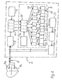
- a time interval storage device 3 is shown in its functional structure and in its interaction with input and output components of the pacemaker on the output side. Its structure is otherwise assumed to be known and therefore neither shown nor explained in the figure.
- the pacemaker 1 is connected via an electrode line 5 with an atrial electrode 7a and a chamber electrode 7b and receives from there a cardiac signal, which is processed in an amplifier stage 9 by means of filter and amplifier stages and a time interval determination stage 11 is supplied, which with a timer 13 in Connection stands.
- the time interval determination stage 11 the above-mentioned relevant time intervals of the cardiac rhythm, ie the PP, RR, PR and RP intervals, are calculated from the (analog) prepared input signal by means of methods of per se known signal analysis Timer 13 determined specific accuracy.
- the time interval determination stage 11 outputs the detected PP, RR, PR and RP intervals separately via four outputs.
- the outputs of the time interval determination stage 11 are connected in each case to an input of a time interval discriminator stage 15 which is connected via a control input to a programmable time lapse memory 17.
- a time grid (according to the second sub-picture from above in Fig. 1 ) before classification of the measured time intervals which is applied in the time interval discriminator stage 15.
- the time interval discriminator stage 15 has a plurality of outputs each associated with one of the preprogrammed time slots for each "channel", ie each processing area associated with an input. Upon registration of a falling in the corresponding period of time a signal is output at the corresponding output, which increments a counter 19 connected there.
- the counters 19 are connected to a memory section 21i of a time-slot memory 21 which has four memory areas 21a, 21b, 21c, 21d for separately storing the frequency distribution of the PP, RR, PR and RP intervals.
- the time segment memory 21 is connected to the input of a cardiac rhythm evaluation stage 23 in which the determined and stored distribution of the relevant time intervals of the patient's cardiac rhythm is evaluated in accordance with a preprogrammed evaluation algorithm and, if appropriate, with the aid of further parameters.
- the cardiac rhythm evaluation stage 23 is finally connected to a stimulation control stage 25, which activates a stimulation pulse generator 27 in accordance with a likewise preprogrammed stimulus pulse therapy for the output of stimulation pulses via the electrode line 5 to the atrial electrode 7a and / or the chamber electrode 7b.
- the dependence of certain stimulation therapies on a particular distribution of the relevant time intervals of the heart rhythm is not the subject of the invention; For this purpose, there are extensive prior art, which is known in the art and can be used in the practice of the invention.
Description
Die Erfindung betrifft ein Verfahren zur Speicherung von Herzrhythmusinformation nach dem Oberbegriff des Anspruchs 1, eine Herzrhythmus-Speichervorrichtung nach dem Oberbegriff des Anspruchs 8 sowie ein implantierbares Stimulationsgerät, in dem ein solches Verfahren bzw. eine solche Speichervorrichtung implementiert ist.The invention relates to a method for storing cardiac rhythm information according to the preamble of claim 1, a cardiac rhythm storage device according to the preamble of claim 8 and an implantable stimulation device in which such a method or such a storage device is implemented.
Die möglichst präzise Erfassung von Herzrhythmusinformationen über hinreichend lange Zeiträume und möglichst in unterschiedlichen physischen und psychischen Situationen eines Patienten ist für den Kardiologen - wie seit langem bekannt ist - ein unverzichtbares Diagnosehilfsmittel. Speziell die Verfolgung zeitlicher Entwicklungen in den Intervallen zwischen Vorhofereignissen (der sogenannten PP-Intervalle) sowie zwischen Kammeraktionen (speziell der sogenannten RR-Intervalle) sowie der zeitlichen Abstände zwischen aufeinanderfolgenden Vorhof- und Kammeraktionen (der PR-Intervalle) bzw. zwischen Kammerund Vorhofaktionen (der RP-Intervalle) erlaubt wertvolle Rückschlüsse auf spezifische Herzrhythmusstörungen.The most precise possible recording of cardiac rhythm information over sufficiently long periods of time and possibly in different physical and psychological situations of a patient is for the cardiologist - as has been known for a long time - an indispensable diagnostic tool. Specifically, the tracking of temporal developments in the intervals between atrial events (the so-called PP intervals) as well as between chamber actions (especially the so-called RR intervals) and the time intervals between successive atrial and ventricle actions (the PR intervals) and between chamber and atrial events ( the RP intervals) allows valuable conclusions about specific cardiac arrhythmias.
Während in der ambulanten und klinischen Praxis des Kardiologen die Erfassung und Aufzeichnung der Herzrhythmusinformationen mittels hochauflösender EKG-Geräte in der Regel möglichst detailreich erfolgt, um dem Arzt neben den oben erwähnten Zeitintervallen wertvolle Kurvenform-Informationen der Herzsignale zu liefern, muss für bestimmte wichtige Einsatzfälle die an einem Patienten über einen bestimmten Zeitraum erfasste Herzrhythmusinformation mit möglichst geringem Aufwand an Verarbeitungsleistung und Speicherkapazität verarbeitet und gespeichert werden. Diese Erfordernis besteht insbesondere bei implantierten Herztherapiegeräten, die in Form von Herzschrittmachern zur Behandlung von bradykarden und/oder tachykarden Herzrhythmusstörungen sowie automatischen Defibrillatoren bzw. Kardiovertern oder auch als kombinierte Schrittmacher/Kardioverter oder implantierte Medikamentendosierpumpen bereits seit längerem bekannt und im praktischen Einsatz sind.While in the ambulatory and clinical practice of the cardiologist recording and recording of cardiac rhythm information using high-resolution ECG devices usually as detailed as possible in order to provide the physician in addition to the above-mentioned time intervals valuable waveform information of the heart signals must be processed and stored for certain important applications, the recorded on a patient over a certain period cardiac rhythm information with the least possible amount of processing power and storage capacity become. This requirement exists in particular in implanted cardiac therapy devices which have long been known and in practical use in the form of pacemakers for the treatment of bradycardic and / or tachycardiac arrhythmias and automatic defibrillators or cardioverters or as combined pacemakers / cardioverter or implanted drug dosing.
Hoch entwickelte Geräte dieser Art sind nämlich mit einem Fühler oder mehreren Fühlern zur Aufnahme diagnostisch relevanter Herzrhythmusinformationen im Körper des Patienten und zugehörigen Signalaufbereitungs- und -verarbeitungsstufen sowie einer Auswertungs- und Steuereinheit ausgestattet, die gemäß einem im Gerät gespeicherten Algorithmus aus einer Menge vorprogrammierter Betriebsparameter bzw. Therapievarianten und Therapiegrößen in Abhängigkeit von der erfassten Herzrhythmusinformation eine Auswahl trifft. Hierzu zählen insbesondere auch Stimulationsgeräte, die in Abhängigkeit vom erfassten Herzzustand des Patienten automatisch aktiviert oder aus einer Betriebsart in eine andere umgeschaltet werden. So erfolgt bei bestimmten Typen automatischer implantierbarer Defibrillatoren und Antitachykardie-Schrittmacher eine laufende Erfassung der Zeitintervalle zwischen Vorhof- und/oder Kammeraktionen über einen hinreichend langen Zeitraum, um lebensbedrohende Beschleunigungen des Herzrhythmus bereits im Ansatz erkennen und mit einer geeigneten Stimulationstherapie darauf reagieren zu können.Highly sophisticated devices of this type are in fact equipped with a sensor or a plurality of sensors for recording diagnostically relevant cardiac rhythm information in the patient's body and associated Signalaufbereitungs- and processing stages and an evaluation and control unit according to an algorithm stored in the device from a set of preprogrammed operating parameters or Therapy variants and therapy sizes depending on the detected cardiac rhythm information makes a selection. These include in particular also stimulation devices that are automatically activated depending on the detected heart condition of the patient or switched from one mode to another. Thus, in certain types of automatic implantable defibrillators and antitachycardia pacemakers, ongoing detection of the time intervals between atrial and / or ventricular events over a sufficiently long period of time involves life-threatening cardiac rhythm enhancements recognize it in the beginning and be able to react to it with a suitable stimulation therapy.
Um die erwähnten lebensbedrohenden Zustände (insbesondere Vorhof- oder Kammerflimmern) bei den verschiedenen bekannten Krankheitsbildern, bei denen die erwähnten automatischen Herzrhythmus-Korrekturgeräte eingesetzt werden, zuverlässig erfassen zu können, muss die Erfassung und Speicherung sich über einen beträchtlichen Zeitraum bzw. eine beträchtliche Anzahl von Herzaktionen erstrecken.In order to be able to reliably detect the mentioned life-threatening conditions (in particular atrial fibrillation or ventricular fibrillation) in the various known clinical pictures in which the above-mentioned automatic cardiac rhythm correction devices are used, the detection and storage must take place over a considerable period of time or a considerable number of times Heart actions extend.
Selbst wenn nur die Zeitintervalle zwischen P- und/oder R-Zacken des Herzsignals erfasst und gespeichert werden und auf die Erfassung, Verarbeitung und Speicherung von Signalforminformation völlig verzichtet wird, wird hierfür eine erhebliche Prozessor- und Speicherkapazität im implantierten Gerät benötigt. Dies ist weniger im Hinblick auf die Kosten der Prozessoren und Speicherbausteine - die natürlich bei erhöhtem Kapazitätsbedarf ebenfalls ansteigen - bedeutsam, sondern viel stärker mit Blick auf den Stromverbrauch und damit die Reduzierung der Batterielebensdauer. Trotz erheblichen Fortschritte in der Primärzellentechnologie und entsprechender Steigerungen der Kapazität der bei implantierten Geräten eingesetzten Lithiumzellen führt bei bekannten Schrittmachern der Energieverbrauch für die Verarbeitung und Speicherung der Zeitintervalle zwischen Herzaktionen zu einer wesentlichen Reduzierung der Batterie- und damit Gerätelebensdauer.Even if only the time intervals between P- and / or R-waves of the cardiac signal are detected and stored and the detection, processing and storage of waveform information is completely eliminated, this requires a considerable amount of processor and memory in the implanted device. This is less significant in terms of the cost of the processors and memory devices - which of course increase with increased capacity requirements - but much more so in terms of power consumption and hence battery life. Despite significant advances in primary cell technology and corresponding increases in the capacity of lithium cells used in implanted devices, in known pacemakers the power consumption for processing and storing the time intervals between cardiac events results in a significant reduction in battery and device lifetimes.
In der Vergangenheit sind mehrfach Vorschläge für Komprimierungsverfahren unterbreitet worden, die speziell zur Vorverarbeitung von Elektrokardiogramminformation vor der Verarbeitung bzw. Speicherung oder allgemein zur Signalkomprimierung für implantierbare, batteriebetriebene Geräte vorgesehen sind.In the past, proposals for compression methods have been made several times, especially for the preprocessing of electrocardiogram information prior to processing or storage, or generally signal compression for implantable, battery powered devices.
So wird in der
In der
In der
In der
Aus der
Aus der
Aus
Aus der
Aus der
Der Erfindung liegt die Aufgabe der Bereitstellung eines verbesserten, einfach und kostengünstig zu implementierenden Verfahrens bzw. eine verbesserten Speichervorrichtung der gattungsgemäßen Art zugrunde, die eine Speicherung von Herzrhythmusinformation mit deutlich verringertem Aufwand an Speicherkapazität und Stromverbrauch ohne wesentlichen Informationsverlust erlauben.The invention is based on the object of providing an improved, simple and inexpensive to implement method or an improved memory device of the generic type, which allow storage of cardiac rhythm information with significantly reduced cost of storage capacity and power consumption without significant loss of information.
Diese Aufgabe wird hinsichtlich ihres Verfahrensaspektes durch ein Verfahren mit den Merkmalen des Anspruchs 1 und hinsichtlich ihres Vorrichtungsaspekts durch eine Speichervorrichtung mit den Merkmalen des Anspruchs 8 gelöst.This object is achieved in terms of its method aspect by a method having the features of claim 1 and in terms of their device aspect by a memory device having the features of claim 8.
Die Erfindung schließt den grundlegenden Gedanken ein, anstelle jedes einzelnen erfassten Zeitintervalls zwischen bestimmten Herzaktionen - also aller einer in einem bestimmten Zeitraum erfassten RR- oder PP- oder PR- oder RP-Intervallen - die Häufigkeit zu speichern, mit der bestimmte Zeitintervall-Werte auftreten. Es ist einsehbar, dass sich hierdurch insbesondere bei weitgehender zeitlicher Konstanz des Herzrhythmus hohe Komprimierungseffekte erzielen lassen. Dieser Vorteil kommt besonders dann zum Tragen, wenn es um die Erfassung und sinnvolle Auswertung verfrühter Vorhof- oder Kammeraktionen (PAC bzw. PVC) innerhalb eines stimulierten, also "starren", Herzrhythmus geht.The invention includes the basic idea of storing the frequency at which certain time interval values occur, rather than each and every detected time interval between certain heart actions - that is, all RR or PP or PR or RP intervals acquired in a particular period of time , It can be seen that this can achieve high compression effects, especially when the cardiac rhythm is largely constant over time. This advantage is particularly useful when it comes to the detection and meaningful evaluation of premature atrial or ventricular Actions (PAC or PVC) within a stimulated, so "rigid", heart rhythm.
Die Erfindung schließt weiterhin den Gedanken ein, dass - entgegen der dem Fachmann geläufigen Sicht - der mit dieser Datenkompression verbundene Informationsverlust für die Verwendung der Herzrhythmusinformation unkritisch ist. Dies trifft für den eben erwähnten Anwendungsfall der Überwachung verfrühter Kontraktionen zwischen stimulierten Herzaktionen in guter Näherung zu.The invention further includes the idea that, contrary to what is known to those skilled in the art, the loss of information associated with this data compression is not critical to the use of cardiac rhythm information. This is true for the just mentioned application of monitoring premature contractions between stimulated heart actions in a good approximation.
Schließlich gehört zur Erfindung der Gedanke, die erwähnten Zeitintervalle gemäß einer vorgegebenen "Rasterung" der Zeitachse zu erfassen bzw. (sofern sie mit höherer Auflösung erfasst wurden) die erfassten Werte einem solchen Raster zuzuordnen. Durch die Wahl der zeitlichen Auflösung des Rasters lässt sich die Kompressionsrate bezüglich des erforderlichen Informationsgehaltes der Herzrhythmusinformation für eine bestimmte Gerätefunktion (z.B. Auslösen einer Antitachykardie-Stimulierung oder einer Kardioversion) weiter optimieren.Finally, the invention includes the idea of detecting the time intervals mentioned in accordance with a predetermined "rastering" of the time axis or (if they were detected with a higher resolution) assigning the detected values to such a raster. By choosing the temporal resolution of the grid, the compression rate with respect to the required information content of the cardiac rhythm information can be for a particular device function (eg, triggering of antitachycardia pacing or cardioversion).
Zur im wesentlichen gleichzeitigen (komprimierten) Speicherung verschiedener Klassen von Zeitintervallen, die für die Auswertung im implantierbaren Gerät voneinander unterschieden werden müssen, wird in einer bevorzugten Ausführung des Verfahrens jeweils eindeutig eine Klassen-Kennzeichnung vergeben. Es erhalten also - vereinfacht gesagt - die Zeitintervalle zwischen aufeinanderfolgenden Kammeraktionen eine Kennzeichnung "RR", die zwischen aufeinanderfolgenden Vorhofaktionen eine Kennzeichnung "PP", die Zeitabstände zwischen einer Vorhof- und einer danach erfolgenden Kammeraktion jeweils die Kennzeichnung "PR" und die Intervalle zwischen einer Kammer- und einer danach auftretenden Vorhofaktion die Kennzeichen "RP". (Es versteht sich, dass in der praktischen Ausführung als Kennzeichnung Zahlenwerte in binärer Darstellung verwendet werden.) Bei der erfindungsgemäßen Abspeicherung der den Abschnitten des gewählten Zeitrasters zugeordneten Messwerten wird dann jeweils die Klassen-Kennzeichnung mitgeführt, und die Zählung der auf die Abschnitte des Zeitrasters entfallenden Registrierungen und die Speicherung der Zählwerte erfolgt separat für die jeweiligen Klassen.For substantially simultaneous (compressed) storage of different classes of time intervals, which must be distinguished from each other for the evaluation in the implantable device, in a preferred embodiment of the method in each case clearly assigned a class marking. Thus, in simple terms, the time intervals between successive chamber actions receive a designation "RR", the time between successive atrial actions a designation "PP", the time intervals between an atrial and a subsequent ventricle action the designation "PR" and the intervals between a Chamber and a subsequent atrial action the license plate "RP". (It is understood that numerical values in binary representation are used in the practical embodiment as identification.) In the inventive storage of the measured values assigned to the sections of the selected time frame, the class marking is then carried respectively and the count of the time intervals Any registrations and the storage of the counts are done separately for the respective classes.
Es versteht sich jedoch, dass das Verfahren für bestimmte Typen implantierbarer Herzrhythmus-Korrekturgeräte, z.B. Antibradykadie-Schrittmacher oder auch bestimmte Defibrillatoren, auf die Erfassung eines einzigen Typs von Herzereignissen und somit einer einzigen Klasse von Zeitintervallen ausgelegt sein kann, womit dann eine klassenbezogen separate Zählung und Speicherung verzichtbar ist. Dies vereinfacht die Signalverarbeitung und -speicherung und verringert damit den Strombedarf hierfür weiter, allerdings um den Preis eines geringeren Informationsgehaltes der gespeicherten Daten.It is understood, however, that for certain types of implantable cardiac rhythm correcting devices, eg, bradycycladie pacemakers or certain defibrillators, the method may be designed to detect a single type of cardiac event, and thus a single class of time interval, which then provides class-by-separate counting and storage is dispensable. This simplifies signal processing and storage and thus reduces it the power requirement for this, but at the cost of a lower information content of the stored data.
Die Ausführung des Verfahrens erfolgt, wie oben bereits angedeutet, bevorzugt durch eine kombinierte Zeitabschnitts-Diskriminierung der gemessenen Intervallwerte bezüglich der vorbestimmten Zeitabschnitte des Zeitrasters und Inkrementierung eines Zählers, welcher demjenigen Abschnitt des Zeitrasters zugeordnet ist, in dem der Intervall-Messwert durch die Diskriminierung eingeordnet wurde. Der Begriff "Zeitraster" besagt bereits, dass die Einteilung des Zeitkontinuums der Herzereignisse in vorbestimmte Abschnitte bevorzugt mit festen Stufen erfolgt. Ein Teil eines entsprechenden Zeitrasters kann beispielsweise Intervalllängen von ..., 901 - 904 ms, 905 - 908 ms, 909 - 1002 ms, ... als Zeitabschnitte umfassen, ist also mit einem Rastermaß von 4 ms gebildet. Es versteht sich, dass auch andere Rastermaße - die den Toleranzbereich der Bewertung von Intervallen als übereinstimmende Intervalle festlegen - verwendet werden können; bevorzugt sind aus derzeitiger Sicht Stufen im Bereich zwischen 2 ms und 20 ms.As already indicated above, the method is preferably carried out by combined time-domain discrimination of the measured interval values with respect to the predetermined time intervals of the time grid and incrementing of a counter associated with that section of the time grid in which the interval measured value is classified by the discrimination has been. The term "time grid" already implies that the division of the time continuum of the cardiac events into predetermined sections preferably takes place with fixed steps. A part of a corresponding time frame can comprise, for example, interval lengths of..., 901-904 ms, 905-908 ms, 909-1002 ms,... As time segments, ie is formed with a grid of 4 ms. It is understood that other grid dimensions - which set the tolerance range of the evaluation of intervals as matching intervals - may also be used; From the current perspective, steps in the range between 2 ms and 20 ms are preferred.
Aus derzeitiger Sicht ist eine Verfahrensführung von besonderem praktischen Vorteil, bei der Paare von RP- und PR-Intervallen jeweils gemeinsam registriert und paarweise gespeichert werden, wobei die Klassenkennzeichnungen einzeln mitgeführt werden oder eine gesonderte Kennzeichnung für das Paar vergeben wird. Dieses Vorgehen ist sinnvoll für die Erfassung der oben erwähnten PVC bzw. PAC im Rahmen eines stimulierten Herzrhythmus.From a current point of view, a methodology of particular practical advantage is that pairs of RP and PR intervals are each registered together and stored in pairs, with the class identifiers individually carried or a separate identifier assigned to the pair. This procedure is useful for the detection of the above-mentioned PVC or PAC in the context of a stimulated heart rhythm.
Gemäß den oben skizzierten Verfahrensaspekten weist eine geeignete Speichervorrichtung (in einer weiten Auslegung dieses Begriffs) Zeitintervall-Diskriminatormittel zur Zuordnung der erfassten Zeitintervalle zu Abschnitten des Zeitrasters, Registrierungszähler zur Ermittlung der den Zeitabschnitten jeweils im Speicherzeitraum zugeordneten Registrierungen und Speicherabschnitte zur Ablage der Anzahl der Registrierungen auf. Zur Festlegung des Registrierungs-Zeitbereiches ist ein Zeitgeber vorgegebenen. Dieser wirkt mit einer Speichersteuerung zweckmäßiger Weise derart zusammen, dass die den einzelnen Zeitabschnitten zugeordneten, gespeicherten Zählwerte in Anlehnung an das bekannte FIFO-Speicherprinzip gehandhabt werden.In accordance with the method aspects outlined above, a suitable memory device (in a broad interpretation of this term) comprises time interval discriminator means for the assignment of the recorded time intervals to sections of the time grid, registration counters for determining the registrations assigned to the time segments respectively in the storage period, and storage sections for storing the number of registrations. To set the registration time range, a timer is given. This interacts expediently with a memory controller in such a way that the stored counter values assigned to the individual time segments are handled on the basis of the known FIFO memory principle.
Es ist also bei fortlaufender Aktualisierung des Speicherstandes jeweils der älteste gespeicherte Zeitintervallwert zu streichen, d. h. der Zählerstand in demjenigen Speicherbereich um 1 zu dekrementieren, in den dieser Intervallwert eingeflossen war. Die Realisierung entsprechender Speichersteuerungen liegt im Bereich fachmännischen Handels und wird daher hier nicht weiter beschrieben.It is therefore to delete the oldest stored time interval value in case of continuous updating of the memory state, d. H. the counter reading in that memory area to decrement by 1, in which this interval value was incorporated. The realization of corresponding memory controls lies in the field of expert trade and will therefore not be described further here.
Die Ausführung der Erfindung kann weitgehend softwaremäßig erfolgen, so dass die im vorangehenden Abschnitt erwähnten Funktionseinheiten nicht als Hardware-Komponenten zu verstehen sind. So kann der Gesamt-Speicherinhalt als Datenwort bzw. Datenstring in einem hardwareseitig unstrukturierten Speicher abgelegt sein, wobei die bestimmten Abschnitten des Zeitrasters zugeordneten Zählwerte durch Bitgruppen an bestimmten Positionen des Datenstrings repräsentiert sind.The execution of the invention can largely be done by software, so that the functional units mentioned in the preceding section are not to be understood as hardware components. Thus, the total memory content can be stored as a data word or data string in a hardware unstructured memory, wherein the specific sections of the time frame associated count values are represented by bit groups at certain positions of the data string.
Die Erfassung der Herzereignisse als solche, d.h., die Extraktion der P- bzw. R-Zacken aus dem analogen Herzsignal, ist dem Fachmann bekannt und nicht Gegenstand der Erfindung, so dass hier auch darauf nicht näher eingegangen wird. Auch die Erfassung des zeitlichen Abstandes zwischen diesen Herzereignissen - also der hier in Rede stehenden Zeitintervalle - liegt im Rahmen fachmännischen Handelns und bedarf daher hier keiner Beschreibung.The detection of the cardiac events as such, ie the extraction of the P or R waves from the analog cardiac signal, is known to the person skilled in the art and is not the subject of the invention, so that no further details are given here becomes. Also, the recording of the time interval between these cardiac events - ie the time intervals in question here - is within the scope of expert action and therefore needs no description here.
Vorteile und Zweckmäßigkeit der Erfindung ergeben sich im übrigen aus den Unteransprüchen sowie der nachfolgenden Beschreibung eines bevorzugten Ausführungsbeispiels anhand der Figuren. Von diesen zeigen:
- Figur 1
- eine grafische Darstellung zur Illustration einer bevorzugten Ausführung des vorgeschlagenen Verfahrens und
- Figur 2
- eine schematische Darstellung von für die Ausführung der Erfindung wesentlichen Komponenten einer bevorzugten Speichervorrichtung.
- FIG. 1
- a graphic representation of a preferred embodiment of the proposed method and
- FIG. 2
- a schematic representation of essential for the practice of the invention components of a preferred storage device.
Im oberen Teil von
- (a) die Zeitintervalle zwischen zwei aufeinanderfolgenden Vorhofaktionen (auch als Vorhofintervalle bezeichnet; PP 1...PPm),
- (b) die Zeitintervalle zwischen aufeinanderfolgenden Kammeraktionen (auch als Kammerintervalle bezeichnet; RR1...RRn),
- (c) die Zeitintervalle zwischen einer Vorhofaktion und einer darauf folgenden Kammeraktion (auch als Vorhof-Kammer-Intervalle bezeichnet; PR1...PRm) und
- (d) die Zeitintervalle zwischen Kammeraktionen und darauffolgenden Vorhofaktionen (auch als Kammer-Vorhof-Intervalle bezeichnet; RP1...RPn).
- (a) the time intervals between two consecutive atrial events (also referred to as atrial intervals; PP 1 ... PPm),
- (b) the time intervals between successive chamber actions (also referred to as chamber intervals; RR1 ... RRn),
- (c) the time intervals between an atrial action and a subsequent ventricle action (also referred to as atrial-ventricular intervals; PR1 ... PRm) and
- (d) the time intervals between chamber actions and subsequent atrial events (also referred to as chamber atrial intervals; RP1 ... RPn).
Unterhalb dieses Teiles von
Unterhalb der gerastert dargestellten Zeitachse ist symbolisch mit vier nebeneinandergestellten Ordinaten und einer gemeinsamen Abszisse dargestellt, dass den Zeitabschnitten jeweils - und zwar für jede Klasse von Zeitintervallen separat - die (als Ordinate aufgetragene) Anzahl der zum jeweiligen Zeitabschnitt gehörenden Registrierungen in Auswertung des Herzsignalverlauf zugeordnet ist. Die dargestellte Häufigkeitsverteilung ist rein willkürlich gewählt.Below the time scale shown in the raster is shown symbolically with four juxtaposed ordinates and a common abscissa that the time periods each - and for each class of time intervals separately - the (plotted as ordinate) number of belonging to the respective period registrations in evaluation of the heart waveform is assigned , The frequency distribution shown is purely arbitrary.
Ganz unten ist - wiederum symbolisch - dargestellt, wie in getrennten Speicherbereichen MPP, MPR, MRR und MRP die bei der Bestimmung der Zeitintervalle belegten Zeitabschnitte jeweils mit der Anzahl der dazugehörigen Registrierungen gespeichert sind. Diese Speicherinhalte stellen die für die Diagnosefunktion eines implantierbaren Herzrhythmus-Korrekturgerätes relevante Datenbasis dar. Sie wird gemäß einem vorprogrammierten Auswertungsalgorithmus fortlaufend zur Gewinnung eines Steuersignals für dieses Gerät benutzt, welches insbesondere ein Verharren im Bereitschaftszustand bzw. die Aktivierung einer Elektrostimulations-Therapie im Falle einer als bedrohlich einzustufenden Verteilung der relevanten Zeitintervalle steuert.At the bottom is shown - again symbolically - how in separate memory areas MPP, MPR, MRR and MRP the time periods used in the determination of the time intervals in each case with the number of associated registrations are stored. This memory content represents the relevant for the diagnostic function of an implantable cardiac rhythm correction device database. It is used in accordance with a pre-programmed evaluation algorithm continuously to obtain a control signal for this device, which in particular a standby state or the activation of an electro-stimulation therapy in case of threateningly classified distribution of the relevant time intervals controls.
In
Der Herzschrittmacher 1 ist über eine Elektrodenleitung 5 mit einer Vorhofelektrode 7a und einer Kammerelektrode 7b verbunden und empfängt von dort ein Herzsignal, welches in einer Verstärkerstufe 9 mittels Filter- und Verstärkerstufen aufbereitet und einer Zeitintervall-Bestimmungsstufe 11 zugeführt wird, welche mit einem Zeitgeber 13 in Verbindung steht. In der Zeitintervall-Bestimmungsstufe 11 werden aus dem (analogen) aufbereiteten Eingangssignal mittels an sich bekannter Verfahren der Signalanalyse die oben erwähnten relevanten Zeitintervalle des Herzrhythmus, also das PP-, RR-, PR- und RP-Intervall, mit einer durch die Genauigkeit des Zeitgebers 13 bestimmten Genauigkeit ermittelt. (In der Praxis wird die hier skizzierte Anordnung mehrkanalig aufgebaut sein-auch ein solcher Aufbau ist aber bekannt und betrifft im übrigen nicht die Erfindung, so dass eine genaue Erläuterung hier verzichtbar ist.) Die Zeitintervall-Bestimmungsstufe 11 gibt über vier Ausgänge die erfassten PP-, RR-, PR- und RP-Intervalle getrennt aus.The pacemaker 1 is connected via an electrode line 5 with an atrial electrode 7a and a chamber electrode 7b and receives from there a cardiac signal, which is processed in an amplifier stage 9 by means of filter and amplifier stages and a time
Die Ausgänge der Zeitintervall-Bestimmungsstufe 11 sind mit jeweils einem Eingang einer Zeitintervall-Diskriminatorstufe 15 verbunden, welche über einen Steuereingang mit einem programmierbaren Zeitrasterspeicher 17 in Verbindung steht. In diesem ist ein Zeitraster (gemäß dem zweiten Teilbild von oben in
Ausgangsseitig ist der Zeitabschnittsspeicher 21 mit dem Eingang einer Herzrhythmus-Auswertungsstufe 23 verbunden, in der gemäß einem vorprogrammierten Auswertungsalgorithmus und gegebenenfalls unter Zuhilfenahme weiterer Parameter die ermittelte und gespeicherte Verteilung der relevanten Zeitintervalle des Herzrhythmus des Patienten ausgewertet wird. Die Herzrhythmus-Auswertungsstufe 23 ist schließlich mit einer Stimulationssteuerstufe 25 verbunden, welche einen Stimulationsimpulserzeuger 27 gemäß einer ebenfalls vorprogrammierten Reizimpulstherapie zur Ausgabe von Reizimpulsen über die Elektrodenleitung 5 an die Vorhofelektrode 7a und/oder die Kammerelektrode 7b ansteuert. Die Abhängigkeit bestimmter Stimulationstherapien von einer bestimmten Verteilung der relevanten Zeitintervalle des Herzrhythmus ist nicht Gegenstand der Erfindung; hierzu gibt es umfangreichen Stand der Technik, der dem Fachmann bekannt ist und bei der Ausführung der Erfindung angewandt werden kann.On the output side, the
Die Ausführung der Erfindung ist nicht auf die oben hervorgehobenen Aspekte und das - lediglich im Sinne einer schematischen Darstellung - erläuterte Ausführungsbeispiel beschränkt, sondern ebenso in einer Vielzahl von Abwandlungen möglich, die im Rahmen fachgemäßen Handelns liegen.The embodiment of the invention is not limited to the aspects highlighted above and the exemplary embodiment explained-merely in the form of a schematic representation-but also in a large number of modifications which are within the scope of expert action.
- 11
- HerzschrittmacherPacemaker
- 33
- Intervall-SpeichervorrichtungInterval storage device
- 55
- Elektrodenleitungelectrode line
- 7a7a
- Vorhofelektrodeatrial electrode
- 7b7b
- Kammerelektrodechamber electrode
- 99
- Eingangsverstärkerinput amplifier
- 1111
- Zeitintervall-BestimmungsstufeTime interval determination stage
- 1313
- Zeitgebertimer
- 1515
- Zeitinvervall-DiskriminatorstufeZeitinvervall discriminator
- 1717
- ZeitrasterspeicherTime pattern memory
- 1919
- Zählercounter
- 2121
- ZeitabschnittsspeicherPeriod memory
- 21a, 21b, 21c, 21d21a, 21b, 21c, 21d
- Speicherbereichstorage area
- 21i21i
- Speicherabschnittstorage section
- 2323
- Herzrhythmus-AuswertungsstufeHeart rhythm evaluation stage
- 2525
- StimulationssteuerstufeStimulation control stage
- 2727
- StimulationsimpulserzeugerStimulation pulse generator
Claims (10)
- A method for storing at least one specific type of existing cardiac rhythm information, in particular a sequence of time intervals between ventricular and/or atrial events, from a time sequence of a plurality of individual cardiac events,
characterized in that- a time interval continuum of the time intervals between the events is divided into time sections having predetermined length, which each receive a unique identifier, in particular a number,- each time interval detected during a detection of the cardiac rhythm is provided with the identifier of the time section in which it falls as a registration,- the number of the registrations from a predetermined total number of detected time intervals or registrations allocated during a predetermined time duration to each identifier is ascertained, and- the identifiers to which at least one registration was assigned from the predetermined number of time intervals or during the predetermined time duration are each stored together with the number of the registrations. - The method according to Claim 1,
characterized in that- multiple classes of time intervals, in particular the various time intervals between ventricular and atrial events, are each uniquely assigned a class identifier,- the class identifier is stored together with the identifier of the time section in which a particular time interval falls, and- the counting of the registrations allocated to the time sections and the storage of the number are performed class-related. - The method according to Claim 1 or 2,
characterized in that- RR intervals between two sequential ventricular events and/or PP intervals between two sequential atrial events and/or PR intervals between sequential atrial and ventricular events and/or RP intervals between ventricular and atrial events are detected for ventricular and/or atrial events as relevant types of cardiac events and- the assigned identifiers of the corresponding time sections are stored class-related, in particular for various classes of time intervals. - The method according to one of the preceding claims,
characterized in that
the ascertainment of the number of the registrations belonging to a time section, building on a type assignment of a newly detected cardiac event, includes- the calculation of the time interval to a cardiac event of identical or different type detected earlier,- a time section discrimination in regard to the predetermined time sections, and- the incrementing of a counter, to which the time section recognized as valid as a result of the discrimination is assigned. - The method according to Claim 3 or 4,
characterized in that RP and PR intervals are each detected in pairs between sequential atrial and ventricular events and/or ventricular and atrial events and the assigned identifiers of these time sections are stored class-related in pairs or combined into a shared identifier of the pair. - The method according to one of the preceding claims,
characterized in that the division into time sections is performed in equal steps, which are predetermined between 2 ms and 20 ms, in particular as 4 ms. - The method according to one of the preceding claims,
characterized in that natural and stimulated cardiac events are subjected to the same registration and storage sequence. - A cardiac rhythm storage device for performing the method according to one of the preceding claims, having at least one storage area for storing the cardiac rhythm information and one timer for establishing a storage time space therefor,
characterized by- time interval discriminator means for assigning time intervals of the cardiac rhythm information detected in the storage time space to one of a plurality of predetermined, uniquely identified time sections in each case,- a plurality of registration counters, corresponding to the plurality of the time sections, for ascertaining the number of the registrations assigned to the individual time sections in the storage time space, and- a plurality of storage sections, corresponding to the plurality of the time sections, which are each permanently assigned to a time section and are implemented for storing the number of the registrations. - The cardiac rhythm storage device according to Claim 8,
characterized by multiple groups of storage areas, each group being assigned uniquely to one class of time intervals and comprising a plurality of storage areas for one predetermined time section within the corresponding class in each case. - An implantable cardiac stimulation apparatus, in particular a pacemaker and/or defibrillator, for influencing the cardiac rhythm using electrical stimulation pulses, having a cardiac rhythm storage device according to Claim 8 or 9.
Applications Claiming Priority (2)
| Application Number | Priority Date | Filing Date | Title |
|---|---|---|---|
| US09/862,082 US6564091B2 (en) | 2001-05-22 | 2001-05-22 | Method and memory means for storing cardiac rhythm information |
| US862082 | 2001-05-22 |
Publications (2)
| Publication Number | Publication Date |
|---|---|
| EP1262143A1 EP1262143A1 (en) | 2002-12-04 |
| EP1262143B1 true EP1262143B1 (en) | 2008-09-17 |
Family
ID=25337599
Family Applications (1)
| Application Number | Title | Priority Date | Filing Date |
|---|---|---|---|
| EP02010671A Expired - Lifetime EP1262143B1 (en) | 2001-05-22 | 2002-05-13 | Method and apparatus for storing heart signal data |
Country Status (3)
| Country | Link |
|---|---|
| US (1) | US6564091B2 (en) |
| EP (1) | EP1262143B1 (en) |
| DE (2) | DE10144655A1 (en) |
Families Citing this family (11)
| Publication number | Priority date | Publication date | Assignee | Title |
|---|---|---|---|---|
| US7840896B2 (en) | 2006-03-30 | 2010-11-23 | Microsoft Corporation | Definition and instantiation of metric based business logic reports |
| US8261181B2 (en) | 2006-03-30 | 2012-09-04 | Microsoft Corporation | Multidimensional metrics-based annotation |
| US8190992B2 (en) | 2006-04-21 | 2012-05-29 | Microsoft Corporation | Grouping and display of logically defined reports |
| US8126750B2 (en) | 2006-04-27 | 2012-02-28 | Microsoft Corporation | Consolidating data source queries for multidimensional scorecards |
| US7702383B2 (en) * | 2006-05-04 | 2010-04-20 | Cardiac Pacemakers, Inc. | Methodology for automated signal morphology analysis in implantable electrotherapy and diagnostic systems |
| US9058307B2 (en) | 2007-01-26 | 2015-06-16 | Microsoft Technology Licensing, Llc | Presentation generation using scorecard elements |
| US8321805B2 (en) | 2007-01-30 | 2012-11-27 | Microsoft Corporation | Service architecture based metric views |
| US8495663B2 (en) | 2007-02-02 | 2013-07-23 | Microsoft Corporation | Real time collaboration using embedded data visualizations |
| DE102007019304A1 (en) * | 2007-04-24 | 2008-11-20 | Airbus Deutschland Gmbh | Operating condition parameter e.g. interior temperature, recording method for e.g. aircraft food cooling device, involves recording time duration when actual value of operating condition parameter is present in each partial value range |
| US9993173B2 (en) * | 2015-09-30 | 2018-06-12 | Biotronik Se & Co. Kg | Analysis of ECG data for arrhythmia |
| WO2018166136A1 (en) * | 2017-03-14 | 2018-09-20 | 华为技术有限公司 | Method and apparatus for processing waveform signal |
Family Cites Families (3)
| Publication number | Priority date | Publication date | Assignee | Title |
|---|---|---|---|---|
| JPS4944513B1 (en) | 1968-05-20 | 1974-11-28 | ||
| DE19609411C2 (en) | 1996-03-04 | 1999-11-25 | Biotronik Mess & Therapieg | Method and device for storing signals in an implantable medical device |
| US6324423B1 (en) * | 1998-04-17 | 2001-11-27 | Timothy Callahan | Quantitative method and apparatus for measuring QT intervals from ambulatory electrocardiographic recordings |
-
2001
- 2001-05-22 US US09/862,082 patent/US6564091B2/en not_active Expired - Lifetime
- 2001-09-11 DE DE10144655A patent/DE10144655A1/en not_active Ceased
-
2002
- 2002-05-13 DE DE50212779T patent/DE50212779D1/en not_active Expired - Lifetime
- 2002-05-13 EP EP02010671A patent/EP1262143B1/en not_active Expired - Lifetime
Also Published As
| Publication number | Publication date |
|---|---|
| DE50212779D1 (en) | 2008-10-30 |
| US20020177784A1 (en) | 2002-11-28 |
| US6564091B2 (en) | 2003-05-13 |
| EP1262143A1 (en) | 2002-12-04 |
| DE10144655A1 (en) | 2002-12-12 |
Similar Documents
| Publication | Publication Date | Title |
|---|---|---|
| DE60122820T2 (en) | Device for reducing the effects of evoked potentials in polarization measurements in a pacemaker system with automatic detection of capture | |
| DE60025486T2 (en) | ADJUSTABLE EVOCATED HEART RESPONSE MEASURING DEVICE FOR AUTOMATIC EXAMINATION | |
| DE60029776T2 (en) | MONITORING DEVICE USING WAVELET TRANSFORMATIONS FOR CARDIAC RATIO ANALYSIS | |
| DE60132407T2 (en) | Implantable pacemaker with automatic selection of the electrode assembly for detecting the evoked response | |
| DE60315068T2 (en) | Differentiation of polymorphic from monomorphic tachyarrhythmias | |
| DE69633957T2 (en) | Implantable device for antitachycardia | |
| DE69727622T2 (en) | Active defibrillator cardiovert medical device with improved tachycardia differentiation | |
| DE69115973T3 (en) | Pacemaker for antitachycardia in an arrhythmia control system | |
| DE69807986T3 (en) | Pacemaker | |
| DE60114969T2 (en) | Prediction of arrhythmia based on changes in morphology of intracardiac ECG signals | |
| DE3732699A1 (en) | IMPLANTABLE HEART PACEMAKER | |
| DE60131041T2 (en) | Implantable cardiac device for monitoring the worsening or improvement of heart disease | |
| EP1262143B1 (en) | Method and apparatus for storing heart signal data | |
| EP1108390B1 (en) | Device for recognition of effect of extrasystols on the circulatory system | |
| EP0583499A1 (en) | Method for detecting cardial ventricular fibrillation and means for detection and treating of cardial ventricular fibrillation | |
| EP2111892B1 (en) | Anti-tachycardic heart stimulator | |
| DE69632673T2 (en) | Pacemaker with evoked response detection | |
| EP2181648B1 (en) | Single chamber heart simulator | |
| DE10151089A1 (en) | Device for predicting tachyarrhythmias | |
| EP2140910B1 (en) | Heart stimulator for treating cardiac tachyarrhythmias | |
| EP0793979A2 (en) | Apparatus for the determination of the heart rate | |
| DE10046241A1 (en) | Pacemaker system with improved classification of physiological events and improved heart monitoring, based on DSP | |
| DE69836881T2 (en) | Apparatus and method for determining a criterion of common or dangerous extrasystoles (atrial or ventricular) | |
| DE69421897T3 (en) | Apparatus for controlling a pacemaker as a function of at least one physiological parameter | |
| DE60302868T2 (en) | Multi-chamber pacing system |
Legal Events
| Date | Code | Title | Description |
|---|---|---|---|
| PUAI | Public reference made under article 153(3) epc to a published international application that has entered the european phase |
Free format text: ORIGINAL CODE: 0009012 |
|
| AK | Designated contracting states |
Kind code of ref document: A1 Designated state(s): AT BE CH CY DE DK ES FI FR GB GR IE IT LI LU MC NL PT SE TR |
|
| AX | Request for extension of the european patent |
Free format text: AL;LT;LV;MK;RO;SI |
|
| 17P | Request for examination filed |
Effective date: 20030128 |
|
| AKX | Designation fees paid |
Designated state(s): CH DE FR GB IT LI NL |
|
| RAP1 | Party data changed (applicant data changed or rights of an application transferred) |
Owner name: BIOTRONIK GMBH & CO. KG |
|
| GRAP | Despatch of communication of intention to grant a patent |
Free format text: ORIGINAL CODE: EPIDOSNIGR1 |
|
| GRAS | Grant fee paid |
Free format text: ORIGINAL CODE: EPIDOSNIGR3 |
|
| GRAA | (expected) grant |
Free format text: ORIGINAL CODE: 0009210 |
|
| STAA | Information on the status of an ep patent application or granted ep patent |
Free format text: STATUS: THE PATENT HAS BEEN GRANTED |
|
| AK | Designated contracting states |
Kind code of ref document: B1 Designated state(s): CH DE FR GB IT LI NL |
|
| REG | Reference to a national code |
Ref country code: GB Ref legal event code: FG4D Free format text: NOT ENGLISH |
|
| REG | Reference to a national code |
Ref country code: CH Ref legal event code: EP |
|
| REF | Corresponds to: |
Ref document number: 50212779 Country of ref document: DE Date of ref document: 20081030 Kind code of ref document: P |
|
| PLBE | No opposition filed within time limit |
Free format text: ORIGINAL CODE: 0009261 |
|
| STAA | Information on the status of an ep patent application or granted ep patent |
Free format text: STATUS: NO OPPOSITION FILED WITHIN TIME LIMIT |
|
| PGFP | Annual fee paid to national office [announced via postgrant information from national office to epo] |
Ref country code: NL Payment date: 20090520 Year of fee payment: 8 |
|
| 26N | No opposition filed |
Effective date: 20090618 |
|
| PGFP | Annual fee paid to national office [announced via postgrant information from national office to epo] |
Ref country code: IT Payment date: 20090526 Year of fee payment: 8 |
|
| REG | Reference to a national code |
Ref country code: NL Ref legal event code: V1 Effective date: 20101201 |
|
| PG25 | Lapsed in a contracting state [announced via postgrant information from national office to epo] |
Ref country code: IT Free format text: LAPSE BECAUSE OF NON-PAYMENT OF DUE FEES Effective date: 20100513 Ref country code: NL Free format text: LAPSE BECAUSE OF NON-PAYMENT OF DUE FEES Effective date: 20101201 |
|
| REG | Reference to a national code |
Representative=s name: RANDOLL, SOEREN, DIPL.-CHEM. UNIV. DR. RER. NA, DE Ref country code: DE Ref legal event code: R082 Ref document number: 50212779 Country of ref document: DE |
|
| REG | Reference to a national code |
Ref country code: DE Ref legal event code: R081 Ref document number: 50212779 Country of ref document: DE Owner name: BIOTRONIK SE & CO. KG, DE Free format text: FORMER OWNER: BIOTRONIK GMBH & CO. KG, 12359 BERLIN, DE Effective date: 20111219 |
|
| PGFP | Annual fee paid to national office [announced via postgrant information from national office to epo] |
Ref country code: GB Payment date: 20120522 Year of fee payment: 11 Ref country code: FR Payment date: 20120608 Year of fee payment: 11 |
|
| GBPC | Gb: european patent ceased through non-payment of renewal fee |
Effective date: 20130513 |
|
| REG | Reference to a national code |
Ref country code: FR Ref legal event code: ST Effective date: 20140131 |
|
| PG25 | Lapsed in a contracting state [announced via postgrant information from national office to epo] |
Ref country code: GB Free format text: LAPSE BECAUSE OF NON-PAYMENT OF DUE FEES Effective date: 20130513 |
|
| PG25 | Lapsed in a contracting state [announced via postgrant information from national office to epo] |
Ref country code: FR Free format text: LAPSE BECAUSE OF NON-PAYMENT OF DUE FEES Effective date: 20130531 |
|
| PGFP | Annual fee paid to national office [announced via postgrant information from national office to epo] |
Ref country code: DE Payment date: 20160504 Year of fee payment: 15 Ref country code: CH Payment date: 20160526 Year of fee payment: 15 |
|
| REG | Reference to a national code |
Ref country code: DE Ref legal event code: R119 Ref document number: 50212779 Country of ref document: DE |
|
| REG | Reference to a national code |
Ref country code: CH Ref legal event code: PL |
|
| PG25 | Lapsed in a contracting state [announced via postgrant information from national office to epo] |
Ref country code: LI Free format text: LAPSE BECAUSE OF NON-PAYMENT OF DUE FEES Effective date: 20170531 Ref country code: CH Free format text: LAPSE BECAUSE OF NON-PAYMENT OF DUE FEES Effective date: 20170531 |
|
| PG25 | Lapsed in a contracting state [announced via postgrant information from national office to epo] |
Ref country code: DE Free format text: LAPSE BECAUSE OF NON-PAYMENT OF DUE FEES Effective date: 20171201 |