EP2338249B1 - Einrichtung und system zum schutzumschalten - Google Patents
Einrichtung und system zum schutzumschalten Download PDFInfo
- Publication number
- EP2338249B1 EP2338249B1 EP08877592.9A EP08877592A EP2338249B1 EP 2338249 B1 EP2338249 B1 EP 2338249B1 EP 08877592 A EP08877592 A EP 08877592A EP 2338249 B1 EP2338249 B1 EP 2338249B1
- Authority
- EP
- European Patent Office
- Prior art keywords
- line
- protection
- unit
- protection unit
- switching
- Prior art date
- Legal status (The legal status is an assumption and is not a legal conclusion. Google has not performed a legal analysis and makes no representation as to the accuracy of the status listed.)
- Not-in-force
Links
Images




Classifications
-
- H—ELECTRICITY
- H04—ELECTRIC COMMUNICATION TECHNIQUE
- H04L—TRANSMISSION OF DIGITAL INFORMATION, e.g. TELEGRAPHIC COMMUNICATION
- H04L1/00—Arrangements for detecting or preventing errors in the information received
- H04L1/22—Arrangements for detecting or preventing errors in the information received using redundant apparatus to increase reliability
-
- G—PHYSICS
- G06—COMPUTING OR CALCULATING; COUNTING
- G06F—ELECTRIC DIGITAL DATA PROCESSING
- G06F11/00—Error detection; Error correction; Monitoring
- G06F11/07—Responding to the occurrence of a fault, e.g. fault tolerance
- G06F11/16—Error detection or correction of the data by redundancy in hardware
- G06F11/20—Error detection or correction of the data by redundancy in hardware using active fault-masking, e.g. by switching out faulty elements or by switching in spare elements
- G06F11/2002—Error detection or correction of the data by redundancy in hardware using active fault-masking, e.g. by switching out faulty elements or by switching in spare elements where interconnections or communication control functionality are redundant
- G06F11/2005—Error detection or correction of the data by redundancy in hardware using active fault-masking, e.g. by switching out faulty elements or by switching in spare elements where interconnections or communication control functionality are redundant using redundant communication controllers
-
- G—PHYSICS
- G06—COMPUTING OR CALCULATING; COUNTING
- G06F—ELECTRIC DIGITAL DATA PROCESSING
- G06F11/00—Error detection; Error correction; Monitoring
- G06F11/07—Responding to the occurrence of a fault, e.g. fault tolerance
- G06F11/16—Error detection or correction of the data by redundancy in hardware
- G06F11/20—Error detection or correction of the data by redundancy in hardware using active fault-masking, e.g. by switching out faulty elements or by switching in spare elements
- G06F11/202—Error detection or correction of the data by redundancy in hardware using active fault-masking, e.g. by switching out faulty elements or by switching in spare elements where processing functionality is redundant
- G06F11/2023—Failover techniques
- G06F11/2028—Failover techniques eliminating a faulty processor or activating a spare
-
- H—ELECTRICITY
- H04—ELECTRIC COMMUNICATION TECHNIQUE
- H04L—TRANSMISSION OF DIGITAL INFORMATION, e.g. TELEGRAPHIC COMMUNICATION
- H04L49/00—Packet switching elements
- H04L49/55—Prevention, detection or correction of errors
- H04L49/552—Prevention, detection or correction of errors by ensuring the integrity of packets received through redundant connections
-
- H—ELECTRICITY
- H04—ELECTRIC COMMUNICATION TECHNIQUE
- H04M—TELEPHONIC COMMUNICATION
- H04M3/00—Automatic or semi-automatic exchanges
- H04M3/18—Automatic or semi-automatic exchanges with means for reducing interference or noise; with means for reducing effects due to line faults with means for protecting lines
-
- G—PHYSICS
- G06—COMPUTING OR CALCULATING; COUNTING
- G06F—ELECTRIC DIGITAL DATA PROCESSING
- G06F11/00—Error detection; Error correction; Monitoring
- G06F11/07—Responding to the occurrence of a fault, e.g. fault tolerance
- G06F11/16—Error detection or correction of the data by redundancy in hardware
- G06F11/20—Error detection or correction of the data by redundancy in hardware using active fault-masking, e.g. by switching out faulty elements or by switching in spare elements
- G06F11/202—Error detection or correction of the data by redundancy in hardware using active fault-masking, e.g. by switching out faulty elements or by switching in spare elements where processing functionality is redundant
- G06F11/2038—Error detection or correction of the data by redundancy in hardware using active fault-masking, e.g. by switching out faulty elements or by switching in spare elements where processing functionality is redundant with a single idle spare processing component
-
- H—ELECTRICITY
- H04—ELECTRIC COMMUNICATION TECHNIQUE
- H04M—TELEPHONIC COMMUNICATION
- H04M3/00—Automatic or semi-automatic exchanges
- H04M3/22—Arrangements for supervision, monitoring or testing
- H04M3/2209—Arrangements for supervision, monitoring or testing for lines also used for data transmission
Definitions
- the present invention relates to a unit and a system for protection switching for line interface units in a telecommunication system.
- the line signals between the communication line and the failed line card are redirected to a stand-by line card.
- An implementation for protection switching known from prior art is to use a fixed bus, a protection bus, in the backplane of the cabinet housing the line cards.
- the protection bus is shared by all line cards. This has the disadvantage that it is not possible to protect a second faulty line card if protection switching already has been performed for a first faulty line card.
- Another disadvantage is that line cards such as 2 Mb/s E1 line cards can not be protected at all.
- a common protection bus introduces severe bridge taps which for example the HDB3 line coding in the E1 line signals does not tolerate.
- Yet another disadvantage is that the standby line card often needs to be of a different design than the other line cards.
- Patent document US 2006/050631 discloses a reconfigurable Automatic Protection Switching featuring point-to-point high speed eraces between backup cards.
- the current invention comprises a protection unit that is adapted to be connected between the communication line and the line card.
- Several protection units can be connected together to form a protection switching system.
- the protection unit comprises a local bridge connector that is adapted to be connected to corresponding bridge connectors in other protection units.
- Each protection unit in the protection switching system is connected to at least one other (e.g. adjacent) protection unit by detachable electrical connection elements via the bridge connectors.
- Each protection unit in the protection switching system is connectable to a corresponding line card where one line card is a standby line card.
- the protection unit further comprises a switching element (e.g. an electrical relay) that in normal operation directs line signals between the communication line and the line card, but when protection switching is needed is adapted to direct the line signals between the communication line and the local bridge connector.
- a switching element e.g. an electrical relay
- the protection unit connectable to the standby line interface unit is further provided with a by-pass element
- the protection switching system is adapted so that when protection switching is needed (e.g. at failure of a line card) the line signal is re-directed between the communication line for the failed line card and the standby line card via the bridge connectors, the detachable electrical connection elements and the by-pass element.
- the protection unit could for example be implemented as a separate printed board assembly connected to the corresponding line card via the backplane in the cabinet.
- the bridge connectors could for example be located in the front of the printed board assembly so that protection units easily can be connected to other protection units by manually inserting the detachable electrical connection elements (e.g. external jumpers or cables) in the bridge connectors.
- One important advantage with the current invention is that different protection switching configurations (1+1 and N+1) can be used in the same sub-rack of a cabinet. Each configuration can have different types of line cards (E1, ADSL etc). Line cards with line signaling sensitive to bridge taps (such as the 2 Mb/s E1 line cards) can now be protected by easily configuring a 1+1 configuration.
- E1, ADSL etc Line cards with line signaling sensitive to bridge taps
- each protection unit can be produced as equal units as they can be connected to a arbitrary type of line cards such as a working E1 or ASDL line card or a standby E1 or ADSL line card. Equal protection units reduce the production and storing costs and the maintenance and other logistics involved are significantly simplified.
- Yet another advantage is that no different design is needed for the standby line card compared to the working line card.
- the objective with the current invention is therefore to allow for a very high degree of flexibility when configuring protection switching in telecommunication systems.
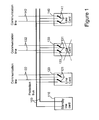
- FIG. 1 illustrates a protection switching system known from prior art.
- Line cards 120,130,140 are connected to corresponding communication lines 122,132,142.
- the communications lines can for example be connected to customer premises equipment CPE, such as modems for digital subscriber lines DSL.
- Each line card 120,130,140 is also connectable to a protection bus 100.
- To the protection bus 100 is also connected a standby line card 110.
- Each line card 120,130,140 also comprises a set of electrical relays 121,131,141. In normal operation the relays 121,131,141 are set so that line signals are directed between the communication lines 122,132,142 and the corresponding line cards 120,130,140.
- the relays 131 are switched in action 133 to a position so that the line signals are directed between the communication line 132 and the protection bus 100 instead.
- the standby line card 110 now takes over the processing of line signals from the communication line 132.
- the line cards 120,130,140 and the standby line card 110 are typically inserted in a cabinet (not shown in Figure 1 ) having a backplane for feeding the cards with power etc.
- the protection bus 100 in Figure 1 is a fixed bus located in said backplane. As the protection bus 100 is fixed, there is no flexibility for having several different protection switching configurations.
- Figure 2 illustrates a protection system 290 comprising three protection units 200,210,220 according the current invention.
- the protection units 200,210,220 and the protection system 290 are located between communication lines 250,240 and line cards 260,270,280.
- Two protection units 200 and 220 are connected to the line cards 270 and 280 respectively.
- the third protection unit 210 is connected to a standby line card 260.
- the protection units 200 and 220 are connected to the communication lines 250, 240 via line connectors 206 and 226 respectively.
- the line connector 216 in the protection unit 210 is in this configuration not used (hatched in Figure 2 ).
- Each protection unit 200,210,220 further comprises a bridge connector 207,217,227.
- the bridge connectors 207,217,227 in the different protection units 200,210,220 are designed to be connected to each other.
- Each bridge connector 207,217,227 is in the embodiment illustrated by Figure 2 divided into a pair of separate bridge connectors 202,212,222 and 203,213,223 where each pair is electrically connected to each other 204,214,224.
- the bridge connectors 207,217,227 are preferably positioned in the front end of the protection units 200,210,220.
- Each bridge connector 202,203,213 etc is designed to receive detachable electrical connection elements 251,252.
- connection elements 251,252 are preferably sets of detachable jumpers or cables. Jumpers can for example be used for connecting two protection units located side-by-side as in Figure 2 and cables can be used between protection units less adjacent to each other.
- Bridge connectors 212 and 223 hatchched in Figure 2 ) are not used in this configuration. Not used connectors can be covered by a proper plastic or metallic lid.
- bridge connector 222 in protection unit 220 is connected to bridge connector 202 in protection unit 200 by the detachable electrical connection element 251 and bridge connector 203 is connected to bridge connector 213 in protection unit 210 by the detachable electrical connection element 252.
- the protection units 200,210,220 can be connected at 205,215,225 to the line cards 270,280 and the standby line card 260 in different ways. Different embodiments on how to do this are described in more detail further below and illustrated by Figure 6 .
- Each protection unit 200,210,220 also comprises a switching element 201,211,221 which in a preferred embodiment is a set of one or more relays.
- the protection unit 210 that is connected to the standby line card 260 is further configured with a electrical by-pass element 218 and an identification element 219 which both could be implemented as detachable internal jumpers.
- the by-pass element 218 is designed to by-pass the switching element 211 and the identification element 219 is designed to identify (for example to a management system) that the protection unit 210 is connected to the standby line card 260. If the protection unit 210 is inserted in a backplane the identification can for example be performed by a read command from a slot management bus in the backplane. Likewise, the switching elements 201,211,221 can be controlled by switch commands from the same slot management bus.
- the switching elements 201,211,221 are set in a 'normal' position 'N'. This means that the line signals 255,245 are directed between the communication lines 250, 240 and the corresponding line card 270,280 and that the bridge connector 217 in protection unit 210 is electrically disconnected from the standby line card 260. If one line card, say line card 280 fails, the switching elements 221 and 211 are set in a 'protection switching' position 'P'.
- Figure 3 illustrates a telecommunication system 3000 having a configuration comprising two protection switching systems 3100,3200 and six line cards 3310,3320,3330,3340,3350,3360 all six line cards mounted in the same sub-rack 3300.
- Protection switching system 3100 is a so called N+1 configuration and consists of four protection units 3110,3120,3130,3140 each unit connected to a corresponding line card 3330,3340,3350,3360 respectively.
- the line cards 3330, 3340, 3350, 3360 are ASDL line cards where one line card 3330 is a standby line card having a by-pass element 3114.
- the four protection units 3110,3120,3130,3140 are interconnected in series by using detachable electrical connection elements such as external jumpers 3115,3125,3135.
- Protection switching system 3200 is a so called 1+1 configuration and consists of two protection units 3210,3220 each unit connected to a corresponding line card 3310,3320 respectively.
- the line cards 3310,3310 are E1 (2 Mb/s) line cards where line card 3310 is a standby line card having a by-pass element 3214.
- the two protection units 3210,3220 are interconnected in series by using an external jumper 3215.
- the two protection switching systems 3100 and 3200 can work independently and have different types of line cards. If for example the ADSL card 3360 fails, protection switching to the standby ADSL card 3330 is performed by setting the switching elements 3111 and 3141 into the 'protection switching' position 'P'. The line signals 3165 are now directed from communication line 3160 to the standby ADSL card 3330 via the detachable connection elements 3135,3125,3115 and the by-pass element 3114.
- protection switching to the standby E1 3310 is performed in a similar way by setting the switching elements 3211 and 3221 into the 'protection switching' position 'P'.
- the line signals 3255 are now directed from communication line 3250 to the standby E1 card 3310 via the detachable connection element 3215 and the by-pass element 3214.
- line cards for line signals sensitive to bridge-taps such as the E1 line cards 3310,3320 can easily be configured in an 1+1 configuration with the external jumper 3215.
- one ADSL card 3360 can be designed to serve a plurality of different ADSL communication lines 3160 (here 64 lines).
- the protection unit 3140 is therefore adapted to serve as many communication lines 3160 as the line card 3360 can serve and has for example a bridge connector 3142 for each communication line 3160.
- the detachable electrical connection element 3135 connected between the bridge connectors 3132 and 3142 also must support a plurality of different communication lines.
- equivalent electrical connection elements here called jumper subunits 715,725,735 comprising a set of jumpers are used.
- jumper subunits 715,725,735 are illustrated in Figure 7a .
- Each jumper subunit 715,725,735 is mounted on two adjacent (side-by-side) protection units 700,710,720,730.
- the protection units 700,710,720,730 are grouped together side-by-side (as done in the protection systems 3100, 3200 in Figure 3 ).
- the front of the jumper subunits 715,725,735 are covered by metallic screens for improved EMI/EMC.
- Figure 7b shows the jumper unit 715 covered by a metallic screen 750.
- the metallic screen 750 is provided with gaskets 751 and 752.
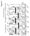
- Two ADSL line cards 4310, 4320 and three SHDSL line cards 4330,4340,4350 have been inserted in two groups in a sub-rack 4300. Each line card is connected to a corresponding protection unit 4110,4120,4130,4140,4150. Line cards 4310 and 4330 are standby line cards.
- the protection units 4110,4120 for the ADSL line cards 4310, 4320 are interconnected with a jumper sub-unit 4201, and the protection units 4130,4140,4150 for the SHDSL line cards 4330,4340,4350 are interconnected with jumper sub-units 4203,4204.
- This new ADSL line card 4360 has to be installed. This new ADSL line card 4360 has to be inserted somewhat distant from the group of other ADSL line cards 4310,4320.
- the new ADSL line card 4360 is connected to a corresponding protection unit 4160.
- Both the group of ADSL line cards 4320,4360 and the group of SDHSL cards 4340,4350 now have protection by the standby line cards 4310 and 4330 respectively, but with the limitation that both groups can not be protected simultaneously.
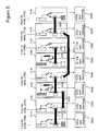
- the jumper sub-units can be replaced with jumper cables where necessary. A configuration illustrating this is found in Figure 5 .
- FIG. 5 three ADSL line cards 5310, 5320, 5340 and an ADSL standby line card 5330 were originally installed together with corresponding protection units 5110,5120, 5140,5130.
- the protection units 5110, 5120, 5140, 5130 are interconnected by three jumper sub-units 5210, 5220 and 5230.
- an E1 line card 5360 and an E1 standby line card 5350 is installed together with corresponding protection units 5150,5160.
- Two new ADSL line cards 5370,5380 are installed together with two corresponding protection units 5170,5180.
- the two new ADSL line cards 5378,5380 are interconnected by a jumper sub-unit 5260.
- Figure 6a illustrates a telecommunication system 600 with a protection unit 610 that is separated from the corresponding line card 613.
- the communication line 602 is connected to the protection unit 610 by a line connector 601.
- the protection unit 610 and the corresponding line card 613 are connected to each other via an interface connector 611 on the protection unit 610 and a backplane 612 in the telecommunication system 600.
- the line connector 601 and bridge connectors 603,604 are located in the front end 605 of the protection unit 610.
- Figure 6b illustrates a second embodiment.
- the protection unit 620 is mounted (piggybacked) in the front of the line card 623 by an interface connector 621.
- the line connector 601 and the bridge connectors 603,604 are located in the front end 605 of the protection unit 620.
- Figure 6c illustrates a third embodiment where the protection unit 630 forms an integrated unit 607 with the line card 633.
- the line connector 601 and the bridge connectors 603,604 are located in the front end 605 of the integrated unit 607.
- protection switching units and system described above are primarily conceived to cope with protection switching when line cards fail. Adding a few additional elements to at least one of the protection units in the system, the protection switching systems described above and illustrated by Figures 2 to 5 can also serve as an aid for testing the communication lines.
- Figure 8 illustrates an example of a protection system 890 having the additional testing features and serving 64 ADSL lines.
- the protection system 890 is limited in Figure 8 to two protection units 800,810.
- Protection unit 810 is connected to the 64 line ADSL lines 815 and a 64 line ADSL line card 870.
- Protection unit 800 is connected to a standby 64 line ADSL line card 850.
- the bridge connectors 803 and 813 in protection units 800 and 810 respectively are interconnected with a jumper subunit 840 (equal to any of the jumper subunits 715,725,735 described above and illustrated by Figure 7a ) or a jumper cable if necessary.
- Protection unit 800 is designed with an on board test head 891 and/or at least one test head connector 892,893.
- the test head connectors 892,893 allow external test heads 861 or other test or telecommunication equipment 862,863 to be connected to the protection unit 800.
- the other telecommunication equipment 862,863 can for example be multiple sub-racks having protection switching systems according to the current invention connected in a daisy chain. By this daisy-chain, a single test equipment can be used for testing communication lines in several protection switching systems.
- test head 891 and test head connectors 892,893 are preferably mounted in the front end of the protection unit 800.
- Bridge connector 802 in protection unit 800 is designed with line taps 880 so that all the 64 ADSL lines are available to a test head switch element 890 which in turn is connected to the test head 891 and/or test head connectors 892,893.
- the test head switch element 890 is designed to select one arbitrary line tap 881 out of the 64 line taps 880.
- switching element 811 in protection unit 810 is set in a 'protection switching' position 'P' for the selected line only and for the remaining 63 communication lines the switching element 811 is set to the 'normal' position 'N'.
- the line signal 816 in the selected line is further directed to bridge connector 802 in protection unit 800 via the bridge connectors 813,803 and the jumper subunit 840.
- the switch element 801 in protection unit 800 is set to the 'normal' position 'N' so that the standby line card 850 is not involved.
- the test head switch element 890 in protection unit 800 is further set to a position so that it is connected to the line tap 881 corresponding to the line that has been selected.
- the line signals 816 for the selected line is now directed to the test head 891 and/or the test head connectors 892,893.
- each of the 64 ADSL lines 815 connected to protection unit 810 are available for testing one by one. In this first test configuration, the line under test is disconnected from the line card 870 and the standby line card 850.
- the line signals 816 for all communication lines 815 are directed to the standby line card 850.
- Switching element 811 in protection unit 810 is set in a 'protection switching' position 'P' for all the 64 ADSL lines 815.
- the switch element 801 in protection unit 800 is also set to the 'protection switching' position 'P' for all the 64 ADSL lines 815.
- the line under test is selected by the test head switch element 890 in the same way as for the first test configuration.
- the main difference from the first test configuration is that in the second test configuration the line under test is still connected to a line card (in this case the standby line card 850).
- a third test configuration is similar to the second test configuration but where the line under test is disconnected from the standby line card 850. This is achieved by setting switching element 801 in protection unit 800 in the 'normal' position 'N' only for the line under test.
Landscapes
- Engineering & Computer Science (AREA)
- Theoretical Computer Science (AREA)
- Signal Processing (AREA)
- Computer Networks & Wireless Communication (AREA)
- Quality & Reliability (AREA)
- Physics & Mathematics (AREA)
- General Engineering & Computer Science (AREA)
- General Physics & Mathematics (AREA)
- Computer Security & Cryptography (AREA)
- Structure Of Telephone Exchanges (AREA)
- Dc Digital Transmission (AREA)
Claims (12)
- Schutzeinheit (200, 210) zum Bereitstellen von Schutzumschalten in einem Telekommunikationssystem, worin die Schutzeinheit (200, 210) in eine Leiterplattenbaugruppe einbezogen und dafür eingerichtet ist, zwischen mindestens eine Kommunikationsleitung (250) und mindestens eine Leitungsschnittstelleneinheit (260, 270) geschaltet zu werden, dadurch gekennzeichnet, dass die Schutzeinheit ferner umfasst:- einen lokalen Brückenverbinder (207, 217), der in der Eingangsstufe (605) der Leiterplattenbaugruppe angeordnet und dafür eingerichtet ist, mindestens ein herausnehmbares elektrisches Verbindungselement (251, 252) aufzunehmen, sodass er mit Brückenverbindern (217, 227) in zwei anderen Schutzeinheiten (210, 220) verbunden werden kann;- ein Schaltelement (201, 211), das dafür eingerichtet ist, im Normalbetrieb Leitungssignale (255) zwischen der Kommunikationsleitung (250) und der Leitungsschnittstelleneinheit (260, 270) zu führen und, wenn Schutzumschalten benötigt wird, die Leitungssignale (255) zwischen der Kommunikationsleitung (250) und dem lokalen Brückenverbinder (207) zu führen;und dass die Schutzeinheit (200, 210) ferner dafür eingerichtet ist, ein herausnehmbares Überbrückungselement (218) aufzunehmen, das dafür eingerichtet ist, das Schaltelement (201, 211) zu überbrücken, sodass Leitungssignale, die vom lokalen Brückenverbinder (217, 227) empfangen werden, zur Leitungsschnittstelleneinheit (260, 270) geführt werden.
- Schutzeinheit (200, 210) nach Anspruch 1, ferner einen Leitungsverbinder (206, 216) zum Koppeln der Leitungssignale (255) zu und von der Kommunikationsleitung (250) umfassend, und worin der Leitungsverbinder (206, 216) in der Eingangsstufe (605) der Leiterplattenbaugruppe angeordnet ist.
- Schutzeinheit (200, 210) nach einem der Ansprüche 1 oder 2, ferner dafür eingerichtet, ein herausnehmbares Identifizierungselement (219) aufzunehmen, das dafür eingerichtet ist, zu kennzeichnen, ob die Leitungsschnittstelleneinheit (260, 270) eine Reserve-Leitungsschnittstelleneinheit (260) ist oder nicht.
- Schutzeinheit (200, 210) nach Anspruch 3, worin das Identifizierungselement (219) von einem Verwaltungssystem lesbar ist.
- Schutzeinheit (610, 620) nach einem der Ansprüche 1 bis 4, ferner einen Schnittstellenverbinder (611, 621) zum Koppeln der Leitungssignale (255) zu und von der Leitungsschnittstelleneinheit (613, 623) umfassend.
- Schutzeinheit (610) nach Anspruch 5, worin der Schnittstellenverbinder (611) über eine Rückwandplatine (612) in dem Telekommunikationssystem (600) mit der Leitungsschnittstelleneinheit (613) verbindbar ist.
- Schutzeinheit (620) nach Anspruch 5, die über den Schnittstellenverbinder (621) direkt an die Leitungsschnittstelleneinheit (623) anschließbar ist.
- Schutzeinheit (630) nach einem der Ansprüche 1 bis 4, die mit der Leitungsschnittstelleneinheit (633) auf der gleichen Leiterplattenbaugruppe (607) integriert ist.
- Schutzeinheit (200, 210) nach einem der vorhergehenden Ansprüche, wobei das Schaltelement (201, 211) mindestens ein elektrisches Relais umfasst.
- System (290) zum Schutzumschalten in einem Telekommunikationssystem, umfassend mindestens eine erste Schutzeinheit (200) nach einem der vorhergehenden Ansprüche und eine zweite Schutzeinheit (210) nach einem der vorhergehenden Ansprüche, die so konfiguriert sind, dass:- die mindestens eine erste Schutzeinheit (200) mit einer Kommunikationsleitung (250) und einer entsprechenden Leitungsschnittstelleneinheit (270) verbindbar ist;- die zweite Schutzeinheit (210) mit einer Reserve-Leitungsschnittstelleneinheit (260) verbindbar ist und mit einem Überbrückungselement (218) versehen ist;- die mindestens eine erste und die zweite Schutzeinheit (200, 210) durch herausnehmbare elektrische Verbindungselemente (252) über die Brückenverbinder (207, 217) miteinander elektrisch verbunden sind; und- worin das System (290) dafür eingerichtet ist, im Normalbetrieb die Leitungssignale (255) zwischen der Kommunikationsleitung (250) und der Leitungsschnittstelleneinheit (270) zu führen und, wenn Schutzumschalten benötigt wird, mittels der herausnehmbaren elektrischen Verbindungselemente (252) und des herausnehmbaren Überbrückungselements (218) zwischen der Kommunikationsleitung (250) und der Reserve-Leitungsschnittstelleneinheit (260) zu führen.
- System (290) nach Anspruch 10, worin die herausnehmbaren elektrischen Verbindungselemente (252) aus externen Steckbrücken bestehen.
- System (290) nach Anspruch 10, worin die herausnehmbaren elektrischen Verbindungselemente (252) aus externen Schaltkabeln bestehen.
Applications Claiming Priority (1)
| Application Number | Priority Date | Filing Date | Title |
|---|---|---|---|
| PCT/SE2008/051200 WO2010047629A1 (en) | 2008-10-23 | 2008-10-23 | Device and system for protection switching |
Publications (3)
| Publication Number | Publication Date |
|---|---|
| EP2338249A1 EP2338249A1 (de) | 2011-06-29 |
| EP2338249A4 EP2338249A4 (de) | 2013-12-11 |
| EP2338249B1 true EP2338249B1 (de) | 2014-12-03 |
Family
ID=42119503
Family Applications (1)
| Application Number | Title | Priority Date | Filing Date |
|---|---|---|---|
| EP08877592.9A Not-in-force EP2338249B1 (de) | 2008-10-23 | 2008-10-23 | Einrichtung und system zum schutzumschalten |
Country Status (4)
| Country | Link |
|---|---|
| US (1) | US8780695B2 (de) |
| EP (1) | EP2338249B1 (de) |
| CN (1) | CN102204150B (de) |
| WO (1) | WO2010047629A1 (de) |
Families Citing this family (4)
| Publication number | Priority date | Publication date | Assignee | Title |
|---|---|---|---|---|
| US9013982B2 (en) | 2011-07-20 | 2015-04-21 | Adc Dsl Systems, Inc. | M-pair mode protection switching |
| US8787151B2 (en) | 2011-07-20 | 2014-07-22 | Adc Dsl Systems, Inc. | N+N protection switching |
| US9318891B2 (en) * | 2012-08-14 | 2016-04-19 | Fisher Controls International Llc | Control signal protection device |
| US9515690B1 (en) | 2014-08-22 | 2016-12-06 | Interstate Electronics Corporation | Receiver with multi-spectrum parallel amplification |
Family Cites Families (17)
| Publication number | Priority date | Publication date | Assignee | Title |
|---|---|---|---|---|
| US4998240A (en) * | 1989-08-15 | 1991-03-05 | C & P Of Virginia | Method of and system for remote testing of integrated services digital networks |
| US5189663A (en) * | 1989-08-15 | 1993-02-23 | C & P Of Virginia | Method of and system for remote testing and reporting of ISDN line conditions |
| US5408462A (en) * | 1993-10-07 | 1995-04-18 | Adc Telecommunications, Inc. | Protection switching apparatus and method |
| US6433988B1 (en) * | 1997-11-05 | 2002-08-13 | Adc Telecommunications, Inc. | Method and apparatus for protection switching |
| US6260155B1 (en) * | 1998-05-01 | 2001-07-10 | Quad Research | Network information server |
| US6529599B1 (en) * | 1998-07-07 | 2003-03-04 | Nec America, Inc. | Flexible tributary unit protection method for a trunk-multiplexed metallic interface |
| US6865693B1 (en) * | 2000-10-19 | 2005-03-08 | Dell Products, L.P. | System and method for debugging multiprocessor systems |
| US7003690B2 (en) * | 2001-05-30 | 2006-02-21 | Juniper Networks, Inc. | Method and apparatus for redundancy switching in line cards |
| US7032135B2 (en) * | 2002-08-02 | 2006-04-18 | Corrigent Systems Ltd. | Equipment protection using a partial star architecture |
| US20040114510A1 (en) | 2002-12-16 | 2004-06-17 | Miller Frank W. | Remote terminal multiplexer/de-multiplexer having protection bus |
| SE0303332A0 (en) * | 2003-12-11 | 2009-03-17 | Nordia Innovation Ab | Method and system for remotely automating crossconnects in telecom networks |
| EP1578167B1 (de) * | 2004-03-09 | 2008-06-18 | Alcatel Lucent | Telekommunikationsvermittlungssystem und Betriebsverfahren |
| US6982952B2 (en) * | 2004-04-20 | 2006-01-03 | Motorola, Inc. | Method and apparatus for bypassing a payload node |
| US7450494B2 (en) * | 2004-09-03 | 2008-11-11 | Cisco Technology, Inc. | Reconfigurable apparatus providing 1:N and 1:1 equipment redundancy for high speed broadband interfaces with 1+1 and 1:N automatic protection switching |
| US7464225B2 (en) * | 2005-09-26 | 2008-12-09 | Rambus Inc. | Memory module including a plurality of integrated circuit memory devices and a plurality of buffer devices in a matrix topology |
| EP1885153A1 (de) * | 2006-08-01 | 2008-02-06 | Alcatel Lucent | Flexibles Einrichtungs- und Verbindungsredundanzschema für einen Media Gateway |
| JP5150146B2 (ja) * | 2007-06-18 | 2013-02-20 | 株式会社東芝 | ケーブル通信装置およびケーブル通信方法 |
-
2008
- 2008-10-23 EP EP08877592.9A patent/EP2338249B1/de not_active Not-in-force
- 2008-10-23 WO PCT/SE2008/051200 patent/WO2010047629A1/en not_active Ceased
- 2008-10-23 US US13/125,614 patent/US8780695B2/en active Active
- 2008-10-23 CN CN200880131676.7A patent/CN102204150B/zh not_active Expired - Fee Related
Also Published As
| Publication number | Publication date |
|---|---|
| WO2010047629A9 (en) | 2010-12-09 |
| CN102204150B (zh) | 2015-01-28 |
| WO2010047629A1 (en) | 2010-04-29 |
| EP2338249A4 (de) | 2013-12-11 |
| EP2338249A1 (de) | 2011-06-29 |
| CN102204150A (zh) | 2011-09-28 |
| US20110286323A1 (en) | 2011-11-24 |
| US8780695B2 (en) | 2014-07-15 |
Similar Documents
| Publication | Publication Date | Title |
|---|---|---|
| EP0749663B1 (de) | Fernmeldevermittlungsanlage mit verbesserter redundanz | |
| CA1252219A (en) | Variable length backplane bus | |
| JP5189014B2 (ja) | 高ポート密度dslamのための組込み型メタリックアクセス | |
| US8780695B2 (en) | Device and system for protection switching | |
| US6917683B2 (en) | Signal splitter with test relays on auxiliary circuit board and system using same | |
| KR20050065447A (ko) | 광대역 원격통신 설비용 필터 시스템 | |
| US20090154049A1 (en) | Network equipment system providing surge protection and DC blocking bypass functionalities | |
| US7032135B2 (en) | Equipment protection using a partial star architecture | |
| US7268993B2 (en) | Integrated protector and splitter | |
| US7760858B2 (en) | Splitter system and test access | |
| EP1760903B1 (de) | Haltedrahteinheit für breitbandtest, haltedrahtplatte für breitbandtest und breitbandtestgerät | |
| RU2353071C1 (ru) | Телекоммуникационный модуль и сборка, включающая телекоммуникационный модуль | |
| US7330543B2 (en) | Termination for a line card in a telecommunication system | |
| EP1662810B1 (de) | Telekommunikationsmodul, Kombination eines Telekommunikationsmoduls und zu mindestens eine Splitter-Schaltungsanordnung, und Anordnung mit zumindestens zwei Telekommunikationsmodulen | |
| US7539298B1 (en) | Passive termination for redundant telecommunication receivers connected to a single twisted pair | |
| KR20050033543A (ko) | Xdsl 접속용 금속 테스트 액세스 | |
| US6829214B1 (en) | Multi-part communications card assembly | |
| EP1578144B1 (de) | Modulare Anordnung im Gebiet der Telekommunikation | |
| WO2007132162A1 (en) | Improvements in xdsl service provision | |
| EP2658276B1 (de) | Telekommunikationseinrichtung | |
| EP1906635B1 (de) | Zugriffsvorrichtung und Verfahren zum Testen von digitalen Teilnehmerleitungen | |
| EP3174272B1 (de) | Splittervorrichtung und -anordnung | |
| US20030197057A1 (en) | Monitor and control port for circuit cards |
Legal Events
| Date | Code | Title | Description |
|---|---|---|---|
| PUAI | Public reference made under article 153(3) epc to a published international application that has entered the european phase |
Free format text: ORIGINAL CODE: 0009012 |
|
| 17P | Request for examination filed |
Effective date: 20110401 |
|
| AK | Designated contracting states |
Kind code of ref document: A1 Designated state(s): AT BE BG CH CY CZ DE DK EE ES FI FR GB GR HR HU IE IS IT LI LT LU LV MC MT NL NO PL PT RO SE SI SK TR |
|
| AX | Request for extension of the european patent |
Extension state: AL BA MK RS |
|
| DAX | Request for extension of the european patent (deleted) | ||
| A4 | Supplementary search report drawn up and despatched |
Effective date: 20131108 |
|
| RIC1 | Information provided on ipc code assigned before grant |
Ipc: H04L 1/22 20060101AFI20131104BHEP Ipc: G06F 11/20 20060101ALI20131104BHEP |
|
| GRAP | Despatch of communication of intention to grant a patent |
Free format text: ORIGINAL CODE: EPIDOSNIGR1 |
|
| RIC1 | Information provided on ipc code assigned before grant |
Ipc: G06F 11/20 20060101ALI20140626BHEP Ipc: H04L 1/22 20060101AFI20140626BHEP |
|
| INTG | Intention to grant announced |
Effective date: 20140708 |
|
| GRAS | Grant fee paid |
Free format text: ORIGINAL CODE: EPIDOSNIGR3 |
|
| GRAA | (expected) grant |
Free format text: ORIGINAL CODE: 0009210 |
|
| AK | Designated contracting states |
Kind code of ref document: B1 Designated state(s): AT BE BG CH CY CZ DE DK EE ES FI FR GB GR HR HU IE IS IT LI LT LU LV MC MT NL NO PL PT RO SE SI SK TR |
|
| REG | Reference to a national code |
Ref country code: GB Ref legal event code: FG4D |
|
| REG | Reference to a national code |
Ref country code: AT Ref legal event code: REF Ref document number: 699912 Country of ref document: AT Kind code of ref document: T Effective date: 20141215 Ref country code: CH Ref legal event code: EP |
|
| REG | Reference to a national code |
Ref country code: IE Ref legal event code: FG4D |
|
| REG | Reference to a national code |
Ref country code: DE Ref legal event code: R096 Ref document number: 602008035742 Country of ref document: DE Effective date: 20150108 |
|
| REG | Reference to a national code |
Ref country code: NL Ref legal event code: VDEP Effective date: 20141203 |
|
| REG | Reference to a national code |
Ref country code: AT Ref legal event code: MK05 Ref document number: 699912 Country of ref document: AT Kind code of ref document: T Effective date: 20141203 |
|
| PG25 | Lapsed in a contracting state [announced via postgrant information from national office to epo] |
Ref country code: LT Free format text: LAPSE BECAUSE OF FAILURE TO SUBMIT A TRANSLATION OF THE DESCRIPTION OR TO PAY THE FEE WITHIN THE PRESCRIBED TIME-LIMIT Effective date: 20141203 Ref country code: ES Free format text: LAPSE BECAUSE OF FAILURE TO SUBMIT A TRANSLATION OF THE DESCRIPTION OR TO PAY THE FEE WITHIN THE PRESCRIBED TIME-LIMIT Effective date: 20141203 Ref country code: FI Free format text: LAPSE BECAUSE OF FAILURE TO SUBMIT A TRANSLATION OF THE DESCRIPTION OR TO PAY THE FEE WITHIN THE PRESCRIBED TIME-LIMIT Effective date: 20141203 Ref country code: NO Free format text: LAPSE BECAUSE OF FAILURE TO SUBMIT A TRANSLATION OF THE DESCRIPTION OR TO PAY THE FEE WITHIN THE PRESCRIBED TIME-LIMIT Effective date: 20150303 Ref country code: NL Free format text: LAPSE BECAUSE OF FAILURE TO SUBMIT A TRANSLATION OF THE DESCRIPTION OR TO PAY THE FEE WITHIN THE PRESCRIBED TIME-LIMIT Effective date: 20141203 |
|
| REG | Reference to a national code |
Ref country code: LT Ref legal event code: MG4D |
|
| PG25 | Lapsed in a contracting state [announced via postgrant information from national office to epo] |
Ref country code: SE Free format text: LAPSE BECAUSE OF FAILURE TO SUBMIT A TRANSLATION OF THE DESCRIPTION OR TO PAY THE FEE WITHIN THE PRESCRIBED TIME-LIMIT Effective date: 20141203 Ref country code: HR Free format text: LAPSE BECAUSE OF FAILURE TO SUBMIT A TRANSLATION OF THE DESCRIPTION OR TO PAY THE FEE WITHIN THE PRESCRIBED TIME-LIMIT Effective date: 20141203 Ref country code: GR Free format text: LAPSE BECAUSE OF FAILURE TO SUBMIT A TRANSLATION OF THE DESCRIPTION OR TO PAY THE FEE WITHIN THE PRESCRIBED TIME-LIMIT Effective date: 20150304 Ref country code: CY Free format text: LAPSE BECAUSE OF FAILURE TO SUBMIT A TRANSLATION OF THE DESCRIPTION OR TO PAY THE FEE WITHIN THE PRESCRIBED TIME-LIMIT Effective date: 20141203 Ref country code: AT Free format text: LAPSE BECAUSE OF FAILURE TO SUBMIT A TRANSLATION OF THE DESCRIPTION OR TO PAY THE FEE WITHIN THE PRESCRIBED TIME-LIMIT Effective date: 20141203 Ref country code: LV Free format text: LAPSE BECAUSE OF FAILURE TO SUBMIT A TRANSLATION OF THE DESCRIPTION OR TO PAY THE FEE WITHIN THE PRESCRIBED TIME-LIMIT Effective date: 20141203 |
|
| PG25 | Lapsed in a contracting state [announced via postgrant information from national office to epo] |
Ref country code: SK Free format text: LAPSE BECAUSE OF FAILURE TO SUBMIT A TRANSLATION OF THE DESCRIPTION OR TO PAY THE FEE WITHIN THE PRESCRIBED TIME-LIMIT Effective date: 20141203 Ref country code: RO Free format text: LAPSE BECAUSE OF FAILURE TO SUBMIT A TRANSLATION OF THE DESCRIPTION OR TO PAY THE FEE WITHIN THE PRESCRIBED TIME-LIMIT Effective date: 20141203 Ref country code: EE Free format text: LAPSE BECAUSE OF FAILURE TO SUBMIT A TRANSLATION OF THE DESCRIPTION OR TO PAY THE FEE WITHIN THE PRESCRIBED TIME-LIMIT Effective date: 20141203 Ref country code: CZ Free format text: LAPSE BECAUSE OF FAILURE TO SUBMIT A TRANSLATION OF THE DESCRIPTION OR TO PAY THE FEE WITHIN THE PRESCRIBED TIME-LIMIT Effective date: 20141203 Ref country code: PT Free format text: LAPSE BECAUSE OF FAILURE TO SUBMIT A TRANSLATION OF THE DESCRIPTION OR TO PAY THE FEE WITHIN THE PRESCRIBED TIME-LIMIT Effective date: 20150403 |
|
| PG25 | Lapsed in a contracting state [announced via postgrant information from national office to epo] |
Ref country code: PL Free format text: LAPSE BECAUSE OF FAILURE TO SUBMIT A TRANSLATION OF THE DESCRIPTION OR TO PAY THE FEE WITHIN THE PRESCRIBED TIME-LIMIT Effective date: 20141203 Ref country code: IS Free format text: LAPSE BECAUSE OF FAILURE TO SUBMIT A TRANSLATION OF THE DESCRIPTION OR TO PAY THE FEE WITHIN THE PRESCRIBED TIME-LIMIT Effective date: 20150403 |
|
| REG | Reference to a national code |
Ref country code: DE Ref legal event code: R097 Ref document number: 602008035742 Country of ref document: DE |
|
| PLBE | No opposition filed within time limit |
Free format text: ORIGINAL CODE: 0009261 |
|
| STAA | Information on the status of an ep patent application or granted ep patent |
Free format text: STATUS: NO OPPOSITION FILED WITHIN TIME LIMIT |
|
| REG | Reference to a national code |
Ref country code: FR Ref legal event code: PLFP Year of fee payment: 8 |
|
| PG25 | Lapsed in a contracting state [announced via postgrant information from national office to epo] |
Ref country code: DK Free format text: LAPSE BECAUSE OF FAILURE TO SUBMIT A TRANSLATION OF THE DESCRIPTION OR TO PAY THE FEE WITHIN THE PRESCRIBED TIME-LIMIT Effective date: 20141203 |
|
| 26N | No opposition filed |
Effective date: 20150904 |
|
| PG25 | Lapsed in a contracting state [announced via postgrant information from national office to epo] |
Ref country code: SI Free format text: LAPSE BECAUSE OF FAILURE TO SUBMIT A TRANSLATION OF THE DESCRIPTION OR TO PAY THE FEE WITHIN THE PRESCRIBED TIME-LIMIT Effective date: 20141203 |
|
| PG25 | Lapsed in a contracting state [announced via postgrant information from national office to epo] |
Ref country code: BE Free format text: LAPSE BECAUSE OF FAILURE TO SUBMIT A TRANSLATION OF THE DESCRIPTION OR TO PAY THE FEE WITHIN THE PRESCRIBED TIME-LIMIT Effective date: 20141203 Ref country code: LU Free format text: LAPSE BECAUSE OF FAILURE TO SUBMIT A TRANSLATION OF THE DESCRIPTION OR TO PAY THE FEE WITHIN THE PRESCRIBED TIME-LIMIT Effective date: 20151023 |
|
| REG | Reference to a national code |
Ref country code: CH Ref legal event code: PL |
|
| PG25 | Lapsed in a contracting state [announced via postgrant information from national office to epo] |
Ref country code: MC Free format text: LAPSE BECAUSE OF FAILURE TO SUBMIT A TRANSLATION OF THE DESCRIPTION OR TO PAY THE FEE WITHIN THE PRESCRIBED TIME-LIMIT Effective date: 20141203 |
|
| REG | Reference to a national code |
Ref country code: IE Ref legal event code: MM4A |
|
| PG25 | Lapsed in a contracting state [announced via postgrant information from national office to epo] |
Ref country code: LI Free format text: LAPSE BECAUSE OF NON-PAYMENT OF DUE FEES Effective date: 20151031 Ref country code: CH Free format text: LAPSE BECAUSE OF NON-PAYMENT OF DUE FEES Effective date: 20151031 |
|
| REG | Reference to a national code |
Ref country code: FR Ref legal event code: PLFP Year of fee payment: 9 |
|
| PG25 | Lapsed in a contracting state [announced via postgrant information from national office to epo] |
Ref country code: IE Free format text: LAPSE BECAUSE OF NON-PAYMENT OF DUE FEES Effective date: 20151023 |
|
| PG25 | Lapsed in a contracting state [announced via postgrant information from national office to epo] |
Ref country code: BG Free format text: LAPSE BECAUSE OF FAILURE TO SUBMIT A TRANSLATION OF THE DESCRIPTION OR TO PAY THE FEE WITHIN THE PRESCRIBED TIME-LIMIT Effective date: 20141203 Ref country code: HU Free format text: LAPSE BECAUSE OF FAILURE TO SUBMIT A TRANSLATION OF THE DESCRIPTION OR TO PAY THE FEE WITHIN THE PRESCRIBED TIME-LIMIT; INVALID AB INITIO Effective date: 20081023 |
|
| PG25 | Lapsed in a contracting state [announced via postgrant information from national office to epo] |
Ref country code: TR Free format text: LAPSE BECAUSE OF FAILURE TO SUBMIT A TRANSLATION OF THE DESCRIPTION OR TO PAY THE FEE WITHIN THE PRESCRIBED TIME-LIMIT Effective date: 20141203 Ref country code: MT Free format text: LAPSE BECAUSE OF FAILURE TO SUBMIT A TRANSLATION OF THE DESCRIPTION OR TO PAY THE FEE WITHIN THE PRESCRIBED TIME-LIMIT Effective date: 20141203 |
|
| REG | Reference to a national code |
Ref country code: FR Ref legal event code: PLFP Year of fee payment: 10 |
|
| REG | Reference to a national code |
Ref country code: FR Ref legal event code: PLFP Year of fee payment: 11 |
|
| PGFP | Annual fee paid to national office [announced via postgrant information from national office to epo] |
Ref country code: DE Payment date: 20181029 Year of fee payment: 11 |
|
| PGFP | Annual fee paid to national office [announced via postgrant information from national office to epo] |
Ref country code: IT Payment date: 20181023 Year of fee payment: 11 Ref country code: FR Payment date: 20181025 Year of fee payment: 11 Ref country code: GB Payment date: 20181029 Year of fee payment: 11 |
|
| REG | Reference to a national code |
Ref country code: DE Ref legal event code: R119 Ref document number: 602008035742 Country of ref document: DE |
|
| PG25 | Lapsed in a contracting state [announced via postgrant information from national office to epo] |
Ref country code: DE Free format text: LAPSE BECAUSE OF NON-PAYMENT OF DUE FEES Effective date: 20200501 |
|
| GBPC | Gb: european patent ceased through non-payment of renewal fee |
Effective date: 20191023 |
|
| PG25 | Lapsed in a contracting state [announced via postgrant information from national office to epo] |
Ref country code: IT Free format text: LAPSE BECAUSE OF NON-PAYMENT OF DUE FEES Effective date: 20191023 Ref country code: FR Free format text: LAPSE BECAUSE OF NON-PAYMENT OF DUE FEES Effective date: 20191031 Ref country code: GB Free format text: LAPSE BECAUSE OF NON-PAYMENT OF DUE FEES Effective date: 20191023 |