EP1578167B1 - Telekommunikationsvermittlungssystem und Betriebsverfahren - Google Patents
Telekommunikationsvermittlungssystem und Betriebsverfahren Download PDFInfo
- Publication number
- EP1578167B1 EP1578167B1 EP04360026A EP04360026A EP1578167B1 EP 1578167 B1 EP1578167 B1 EP 1578167B1 EP 04360026 A EP04360026 A EP 04360026A EP 04360026 A EP04360026 A EP 04360026A EP 1578167 B1 EP1578167 B1 EP 1578167B1
- Authority
- EP
- European Patent Office
- Prior art keywords
- sdh
- protection
- hardware
- link
- module
- Prior art date
- Legal status (The legal status is an assumption and is not a legal conclusion. Google has not performed a legal analysis and makes no representation as to the accuracy of the status listed.)
- Expired - Lifetime
Links
- 238000011017 operating method Methods 0.000 title abstract description 5
- 238000000034 method Methods 0.000 claims description 12
- 230000003287 optical effect Effects 0.000 claims description 12
- 238000004590 computer program Methods 0.000 claims description 3
- 230000005540 biological transmission Effects 0.000 description 4
- 102100040338 Ubiquitin-associated and SH3 domain-containing protein B Human genes 0.000 description 3
- 101710143616 Ubiquitin-associated and SH3 domain-containing protein B Proteins 0.000 description 3
- 230000001360 synchronised effect Effects 0.000 description 2
- 101150012532 NANOG gene Proteins 0.000 description 1
- 101100396520 Saccharomyces cerevisiae (strain ATCC 204508 / S288c) TIF3 gene Proteins 0.000 description 1
- 239000000835 fiber Substances 0.000 description 1
- 101150038107 stm1 gene Proteins 0.000 description 1
Images


Classifications
-
- H—ELECTRICITY
- H04—ELECTRIC COMMUNICATION TECHNIQUE
- H04J—MULTIPLEX COMMUNICATION
- H04J3/00—Time-division multiplex systems
- H04J3/02—Details
- H04J3/14—Monitoring arrangements
-
- H—ELECTRICITY
- H04—ELECTRIC COMMUNICATION TECHNIQUE
- H04Q—SELECTING
- H04Q2213/00—Indexing scheme relating to selecting arrangements in general and for multiplex systems
- H04Q2213/13003—Constructional details of switching devices
-
- H—ELECTRICITY
- H04—ELECTRIC COMMUNICATION TECHNIQUE
- H04Q—SELECTING
- H04Q2213/00—Indexing scheme relating to selecting arrangements in general and for multiplex systems
- H04Q2213/13167—Redundant apparatus
-
- H—ELECTRICITY
- H04—ELECTRIC COMMUNICATION TECHNIQUE
- H04Q—SELECTING
- H04Q2213/00—Indexing scheme relating to selecting arrangements in general and for multiplex systems
- H04Q2213/1334—Configuration within the switch
-
- H—ELECTRICITY
- H04—ELECTRIC COMMUNICATION TECHNIQUE
- H04Q—SELECTING
- H04Q2213/00—Indexing scheme relating to selecting arrangements in general and for multiplex systems
- H04Q2213/13341—Connections within the switch
-
- H—ELECTRICITY
- H04—ELECTRIC COMMUNICATION TECHNIQUE
- H04Q—SELECTING
- H04Q2213/00—Indexing scheme relating to selecting arrangements in general and for multiplex systems
- H04Q2213/13367—Hierarchical multiplexing, add-drop multiplexing
Definitions
- This invention relates to a telecommunication switch to be used in public switching telephony networks, comprising a plurality of Synchronous Digital Hierarchy (SDH) hardware interfaces, each comprising working link connecting means, being designed to be connected to a working SDH link and protection link connecting means, being designed to be connected to a protection SDH link associated to the working SDH link of the SDH hardware interface, wherein to each of said SDH hardware interfaces a SDH termination module is connected and an operating method for handling SDH signals transmitted by a protection SDH link associated to a working SDH link of a SDH hardware interface of a telecommunication switch according to the invention.
- SDH Synchronous Digital Hierarchy
- SDH is an international digital telecommunications network hierarchy which standardises transmission around the bit rate of 51.84 megabits per second, which is also called STS-1. Multiples of this bit rate comprise higher bit rate streams. Thus STS-3 is 3 times STS-1, STS-12 is 12 times STS-1, and so on. STS-3 is the lowest bit rate expected to carry ATM traffic, and is also referred to as Synchronous Transport Module-Level 1 (STM-1).
- STM-1 Synchronous Transport Module-Level 1
- a working SDH link is defined as a default link for transferring data (working SDH signals) to be switched by the telecommunication switch.
- a protection link is defined as a link for transferring the data (protection SDH signals) to be switched by the telecommunication switch in case of a failure occurring on the primary link.
- Primary and secondary link may be implemented as an electrical and/or an optical data transmission connection.
- a telecommunication switch is equipped with means for switching (protection switching) data received from the primary and the secondary link to spare hardware elements in case of failure of a hardware element, e.g. a SDH hardware interface (applique) and/or a SDH termination module, used for switching the data. These means are called Equipment Protection Switching (EPS) means or equipment protection arrangement.
- An applique is used for switching data transmitted by SDH links according to a destination of the data. According to known physical reasons each SDH link has to be connected to a SDH termination module. Therefore a SDH termination module is connected to each applique .
- a separate equipment protection switch using extra space in a rack, wherein the hardware modules of a telecommunication switch are positioned, is used to switch SDH links, meaning working and/or protection link, from an active to a spare termination equipment.
- Each equipment protection switch is associated to a group (protection group) of a number N of SDH hardware interfaces and SDH termination modules. Different solutions are used for equipment protection switching, depending on whether electrical or optical transmission connections are used.
- the document US 2003/043734 A1 (TAKEGUCHI KOJI) 6 March 2003 (2003-03-06) relates to an SDH transmission technique where an SDH equipment is provided with switching means which performs a line switching control between working lines and protection lines, in accordance with setting informations sent by setting information transfer means. An occurrence of disagreement of setting information on the line switching control can be prevented and a normal switching operation between opposite equipments can always be performed.
- the object concerning the telecommunication switch is attained by the telecommunication switch defined in claim 1.
- the object concerning an operating method for handling SDH signals transmitted by a protection SDH link of the telecommunication switch is attained by the method according to claim 7.
- the inventive telecommunication switch is comprising:
- said equipment protection arrangement is being designed to forward said protection SDH signals to said first SDH hardware interface using the second SDH connection of said first SDH hardware interface.
- an existing connection between the SDH termination module and the SDH hardware interface is used to forward the protection SDH signals to the SDH termination module if no failure has occurred. Therefore existing standard SDH termination modules having no supplementary connection can be used.
- said equipment protection arrangement of the inventive telecommunication switch is comprising a primary connecting link and a secondary connecting link, both connecting said protection switching hardware module and said spare SDH termination module, wherein said equipment protection arrangement is being designed to forward said protection SDH signals from said protection switching hardware module to said spare SDH termination module using said secondary connecting link and said first SDH hardware interface is being designed to forward working SDH signals transmitted by said working SDH link of said first SDH hardware interface to said equipment protection arrangement. Furthermore, said equipment protection arrangement is being designed to forward said working SDH signals from said protection switching hardware module to said spare SDH termination module using said primary connecting link.
- both received signals, the protection SDH signals and the working SDH signals can be switched to the spare SDH termination module in case of a failure which has occurred in a SDH termination module of an applique connected to the links, which transmit the signals. This results in an Automatic Protection Switching.
- said protection switching hardware module is located in a rear position of said spare SDH termination module.
- no slot position is occupied in the rack of the inventive telecommunication switch by the protection switching hardware module.
- said protection switching hardware module is comprising a signal converter connected to said SDH hardware interfaces by a protection control bus, said signal converter being designed to switch control signals exchanged by said protection switching hardware module and said SDH termination modules on said protection control bus. Because of the signal converter, no supplementary hardware module is necessary to control the switching of the SDH signals. Also the decision how to switch and where to forward the different SDH signals according to a protection switching control signal may be made by the signal converter.
- SDH termination modules connected to said SDH hardware interfaces are comprising electrical SDH termination modules and optical SDH termination modules, both kind of signals, electrical and optical signals, transmitted by SDH links connected to the telecommunication switch can be switched according to their destination.
- the inventive method for handling protection SDH signals transmitted by a protection SDH link associated to a working SDH link of a first SDH hardware interface of a telecommunication switch is comprising the steps of:
- the inventive method is to be used to handle protection SDH signals to be switched by an inventive telecommunication switch. Therefore, it provides the advantages of the inventive telecommunication switch.
- said switching of said protection SDH signals to said SDH termination module being connected to said first SDH hardware interface is being carried out by forwarding said protection SDH signals from said equipment protection arrangement to said first SDH hardware interface by using a connection between said equipment protection arrangement and a second SDH connection of said first SDH hardware interface and forwarding said protection SDH signals from said first SDH hardware interface to said SDH termination module being connected to said first SDH hardware interface.
- This preferred method is used to forward protection SDH signals from the equipment protection arrangement to the SDH termination module in case of an indirect connection.
- said switching of said protection SDH signals to said spare SDH termination module is being carried out by forwarding said protection SDH signals from a protection switching hardware module of said equipment protection arrangement to said spare SDH termination module by using a secondary connecting link between said protection switching hardware module and said spare SDH termination module and working SDH signals transmitted by said working SDH link of said first SDH hardware interface are forwarded to said equipment protection arrangement by said first SDH hardware interface. Furthermore, said working SDH signals are forwarded from said protection switching hardware module to said spare SDH termination module using a primary connecting link between said protection switching hardware module and said spare SDH termination module.
- both received signals, the protection SDH signals and the working SDH signals, can be switched to the spare SDH termination module in case of a failure, which has occurred in a SDH termination module of an applique connected to the links which transmit the signals. This results in an Equipment Protection Switching.
- the inventive telecommunication switch preferably said equipment protection arrangement is comprising at least one microcomputer loaded with a computer program with software code sections by which the switching of control signals on said protection control bus is controlled to carry out the inventive method.
- said equipment protection arrangement is comprising at least one microcomputer loaded with a computer program with software code sections by which the switching of control signals on said protection control bus is controlled to carry out the inventive method.
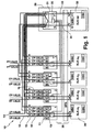
- inventive telecommunication switch 10 comprising a plurality of SDH termination modules (electrical and/or optical) and a plurality of appliques 1,2,3,4, meaning hardware interfaces for connecting the telecommunication switch to SDH links 12, 14, allocated to said SDH terminations is shown.
- SDH connections 12,14 used to forward protection SDH signals or working SDH signals of a SDH hardware interface 1 in case of default routing, when no failure has occurred are shown as thick black lines.
- the telecommunication switch 10 is comprising an equipment protection arrangement 30 comprising at least a protection switching hardware module 31 (protection applique) and a spare SDH termination module 32.
- a working SDH link 12 is connected to the applique 1 of a working SDH termination module 20 and the protection SDH link 14 associated to this working SDH link 12 is connected to the applique 2 of another SDH termination module, from which the protection SDH signals transmitted by the protecting SDH link 14 is forwarded to the protection applique 31 and back to said applique 1 of the working SDH termination 20.
- the protection switching hardware module 31 is further comprising a signal converter (SC) 35, which is designed to switch control signals for each SDH termination module and the protection applique 31 itself.
- SC signal converter
- the signal converter 35 is connected preferably by coax cable links to each applique 1,2,3,4 and the spare SDH termination module 32 via a protection control bus 36.
- the working SDH links (STM1-pn, wherein n is a number between 1 and 4) and the protection SDH links (STM1-sn, wherein n is a number between 1 and 4) are connected to the appliques by coax cables.
- the invention is not restricted to STM1 SDH links. It may also be applied, e.g. to STM4, STM16 and/or OC3 SDH links.
- the Protection Control Bus 36 is part of the Back Panel Assembly (BPA) of the telecommunication switch 10.
- the protection applique 31 is connected to the spare SDH termination module 32 by a primary connecting link (p) 33 and a secondary connecting link (s) 34.
- Each SDH hardware interface 1,2,3,4 is connected to the protection application 31 of the equipment protection arrangement 30 by a first SDH connection 15 and a second SDH connection 16. Both, the first SDH connection and the second SDH connection are implemented as SDH links via wire pairs.
- the appliques are comprising working link connection means 11 and protection link connecting means 13, both marked E/x in the figure.
- E/x stands for either "Electrical to Optical Converter” (E/O) or “Electrical to Electrical Converter” (E/E). In practice, E/O is a fiber transceiver and E/E is a magnetic transformer.
- Each of the active SDH termination modules (XLK-an, wherein n is a number between 1 and 4) and the spare SDH termination module 32 is comprising a Mounted Board Converter (MBC) and an On Board Controller (OBC).
- MBC Mount
- the shown telecommunication switch is able to perform an Embedded Equipment Protection Switching (EPS) for optical and electrical SDH Termination Equipment.
- EPS Embedded Equipment Protection Switching
- N:1 Equipment Protection Switching with flexible usage of slots in the rack of the telecommunication switch and optimized usage of available space. No other equipment space has to be used than that for active and spare termination equipment.
- the same equipment protection system for optical and electrical SDH terminations can be used.
- an Equipment Protection Switch (EPS) is distributed over the appliques of the SDH terminating modules.
- Each working SDH link (according to Automatic Protection Switching) is connected to the applique (first SDH hardware interface) of a working SDH termination module and each protecting SDH link is connected to another applique (second SDH hardware interface) of another SDH termination module.
- an electrical signal is linked to the first SDH hardware interface (working applique) over a protection applique, which is located in the rear position of the spare SDH termination module.
- the working SDH link is connected via the first SDH hardware interface (XLK applique) to the associated SDH termination module (XLK-a n ).
- the protected SDH link is connected to another applique (second SDH hardware interface) of another SDH termination module (XLK-a n+1 ).
- the protection SDH signal is forwarded to the protection applique connected to the spare SDH termination module (XLK-sp).
- the protection SDH signal is forwarded to the same applique (first SDH hardware interface) and SDH termination module as the working SDH signal transmitted on the working SDH link. This describes the normal operating mode.
- FIG 2 the signal routing in case of a failure of the SDH termination module (XLK-a) 100 is shown.
- the SDH connections used to forward protection SDH signals or working SDH signals of a SDH hardware interface in case a failure of the SDH termination module are shown as thick black lines.
- the spare SDH termination module (XLK-sp) has to take over the functionality of the failed SDH termination module. This implies, that the signal of the working SDH link is switched from the applique of the failed module to the protection applique (XLK-sp applique) and from the protection applique to the spare SDH termination module. In this case, the signals transmitted on both links, the protection SDH signal and the working SDH signal, are switched on the XLK-sp applique and to the spare terminating module (XLK-sp).
- FIG 3 the signal routing in case of a failure of an applique (XLK-Applique) 200 is shown. This initiates an Automatic Protection Switch (APS) case and the payload of the failed applique is extracted at the XLK-sp applique from the protection SDH signal transmitted on the protection SDH link, which is forwarded to the protection applique.
- APS Automatic Protection Switch
- the SDH connections used to forward protection SDH signals of a SDH hardware interface in case a failure of the SDH hardware interface are shown as thick black lines.
Landscapes
- Engineering & Computer Science (AREA)
- Computer Networks & Wireless Communication (AREA)
- Signal Processing (AREA)
- Monitoring And Testing Of Exchanges (AREA)
- Data Exchanges In Wide-Area Networks (AREA)
- Transmitters (AREA)
- Mobile Radio Communication Systems (AREA)
- Use Of Switch Circuits For Exchanges And Methods Of Control Of Multiplex Exchanges (AREA)
- Telephonic Communication Services (AREA)
- Optical Communication System (AREA)
Claims (10)
- Telekommunikationsvermittlungseinrichtung (10), umfassend- eine Vielzahl von SDH-Hardwareschnittstellen (1, 2, 3, 4), jede umfassend aktive Leitungsverbindungsmittel (11), die zum Anschluß an eine aktive SDH-Leitung (12) ausgelegt sind, und Schutzleitungsverbindungsmittel (13), die zum Anschluß an eine Schutz-SDH-Leitung (14) ausgelegt sind, die der aktiven SDH-Leitung der SDH-Hardwareschnittstelle zugeordnet ist, in welcher an jeder SDH-Hardwareschnittstelle ein SDH-Abschlußmodul (20) angeschlossen ist, und gekennzeichnet durch- eine Ausrüstungsschutzanordnung (30), umfassend ein protection-switching-Hardwaremodul (31) und ein Rrsatz-SDH-Abschlußmodul (32), in welchem- jede SDH-Hardwareschnittstelle (1, 2, 3, 4) an der Ausrüstungsschutzanordnung (30) durch eine erste SDH-Verbindung (15) und eine zweite SDH-Verbindung (16) angeschlossen wird, und die Schutz-SDH-Leitung (14) einer ersten SDH-Hardwareschnittstelle (1) der SDH-Hardwareschnittstellen (1, 2, 3, 4) an eine zweite SDH-Hardwareschnittstelle (2) der SDH-Hardwareschnittstellen (1, 2, 3, 4) angeschlossen wird,- die zweite SDH-Hardwareschnittstelle (2) zur Weiterleitung von Schutz-SDH-Signalen ausgelegt ist, die durch die Schutz-SDH-Leitung (14) der ersten SDH-Hardwareschnittstelle (1) an die Ausrüstungsschutzanordnung (30) unter Verwendung ihrer ersten SDH-Verbindung (15) gesendet wurden, und- die Ausrüstungsschutzanordnung (30), die zur Vermittlung der Schutz-SDH-Signale an das Ersatz-SDH-Abschlußmodul (32) ausgelegt ist, oder das SDH-Abschlußmodul (20), das an der ersten SDH-Hardwareschnittstelle (1) gemäß einem protection-switching-Steuersignal angeschlossen wird.
- Die Telekommunikationsvermittlungseinrichtung nach Anspruch 1, dadurch gekennzeichnet, daß die Ausrüstungsschutzanordnung zur Weiterleitung der Schutz-SDH-Signale an die erste SDH-Hardwareschnittstelle unter Verwendung der zweiten SDH-Verbindung der ersten SDH-Hardwareschnittstelle ausgelegt ist.
- Die Telekommunikationsvermittlungseinrichtung nach Anspruch 1, dadurch gekennzeichnet, daß die Ausrüstungsschutzanordnung eine primäre Verbindungsleitung (33) und eine sekundäre Verbindungsleitung (34) umfaßt, die beide das protection-switching-Hardwaremodul (31) und das Ersatz-SDH-Abschlußmodul (32) verbinden, in welcher- die Ausrüstungsschutzanordnung zur Weiterleitung der Schutz-SDH-Signale vom protection-switching-Hardwaremodul an das Ersatz-SDH-Abschlußmodul unter Verwendung der sekundären Verbindungsleitung ausgelegt ist, und- die erste SDH-Hardwareschnittstelle zur Weiterleitung der aktiven SDH-Signale ausgelegt ist, die durch die aktive SDH-Leitung der ersten SDH-Hardwareschnittstelle an die Ausrüstungsschutzanordnung übertragen wurden, und- die Ausrüstungsschutzanordnung zur Weiterleitung der aktiven SDH-Signale vom protection-switching-Hardwaremodul an das Ersatz-SDH-Abschlußmodul unter Verwendung der primären Verbindungsleitung ausgelegt ist.
- Die Telekommunikationsvermittlungseinrichtung nach Anspruch 1, dadurch gekennzeichnet, daß sich das protection-switching-Hardwaremodul auf einer hinteren Position des Ersatz-SDH-Abschlußmoduls befindet.
- Die Telekommunikationsvermittlungseinrichtung nach Anspruch 1, dadurch gekennzeichnet, daß das protection-switching-Hardwaremodul einen Signalwandler (35) umfaßt, der mit den SDH-Hardwareschnittstellen durch einen Schutzsteuerungsbus (36) verbunden ist, wobei der Signalwandler (35) zur Vermittlung von Steuersignalen ausgelegt ist, die durch das protection-switching-Hardwaremodul und SDH-Abschlußmodul auf dem Schutzsteuerungsbus ausgetauscht wurden.
- Die Telekommunikationsvermittlungseinrichtung nach Anspruch 1, dadurch gekennzeichnet, daß die SDH-Abschlußmodule, die an den SDH-Hardwareschnittstellen angeschlossen sind, elektrische SDH-Abschlußmodule und optische SDH-Abschlußmodule umfassen.
- Verfahren zur Verarbeitung von Schutz-SDH-Signalen, die durch eine Schutz-SDH-Leitung übertragen wurden, die einer aktiven SDH-Leitung einer ersten SDH-Hardwareschnittstelle der Telekommunikationsvermittlungs-einrichtung zugeordnet ist, nach Anspruch 1, gekennzeichnet durch die Schritte- Empfangen der Schutz-SDH-Signale durch eine zweite SDH-Hardwareschnittstelle der Telekommunikationsvermittlungseinrichtung,- Senden der Schutz-SDH-Signale durch die zweite SDH-Hardwareschnittstelle an eine Ausrüstungsschutzanordnung durch Verwendung einer ersten SDH-verbindung der zweiten SDH-Hardwareschnittstelle mit der Ausrüstungsschutzanordnung,- Vermitteln der Schutz-SDH-Signale durch die Ausrüstungsschutzanordnung an ein Ersatz-SDH-Abschlußmodul der Ausrüstungsschutzanordnung oder an ein SDH-Abschlußmodul, das an der ersten SDH-Hardwareschnittstelle angeschlossen ist, gemäß einem protection-switching-Steuersignal.
- Das Verfahren nach Anspruch 7, dadurch gekennzeichnet, daß die Vermittlung der Schutz-SDH-Signale an das SDH-Abschlußmodul, das an der ersten SDH-Hardwareschnittstelle angeschlossen ist, durch Weiterleitung der Schutz-SDH-Signale von der Ausrüstungsschutzanordnung an die erste SDH-Hardwareschnittstelle unter Verwendung einer Verbindung zwischen der Ausrüstungsschutzanordnung und einer zweiten SDH-Verbindung der ersten SDH-Hardwareschnittstelle und Senden der Schutz-SDH-Signale von der ersten SDH-Hardwareschnittstelle an das SDH-Abschlußmodul durchgeführt wird, das an der ersten SDH-Hardwareschnittstelle angeschlossen ist.
- Das Verfahren nach Anspruch 7, dadurch gekennzeichnet, daß- die Vermittlung der Schutz-SDH-Signale an das Ersatz-SDH-Abschlußmodul durch Weiterleitung der Schutz-SDH-Signale von einem protection-switching-Hardwaremodul der Ausrüstungsschutzanordnung an das Ersatz-SDH-Abschlußmodul unter Verwendung einer sekundären Verbindungsleitung zwischen dem protection-switching-Hardwaremodul und dem Ersatz-SDH-Abschlußmodul erfolgt, und- die aktiven SDH-Siqnale, die durch die aktive SDH-Leitung der ersten SDH-Hardwareschnittstelle übertragen wurden, an die Ausrüstungsschutzanordnung durch die erste SDH-Hardwareschnittstelle weitergeleitet werden, und- die aktiven SDH-Signale vom protection-switching-Hardwaremodul an das Ersatz-SDH-Abschlußmodul unter Verwendung einer primären Verbindungsleitung zwischen dem protection-switching-Hardwaremodul und dem Ersatz-SDH-Abschlußmodul weitergeleitet werden.
- Die Telekommunikationsvermittlungseinrichtung nach Anspruch 5, dadurch gekennzeichnet, daß die Ausrüstungsschutzanordnung mindestens einen Mikrocomputer umfaßt, der mit einem Computerprogramm mit Softwarecodeabschnitten geladen ist, durch welche die Vermittlung der Steuersignale auf dem Schutzsteuerungsbus gesteuert wird, um das Verfahren nach Anspruch 7 durchzuführen.
Priority Applications (4)
| Application Number | Priority Date | Filing Date | Title |
|---|---|---|---|
| DE602004014468T DE602004014468D1 (de) | 2004-03-09 | 2004-03-09 | Telekommunikationsvermittlungssystem und Betriebsverfahren |
| AT04360026T ATE398904T1 (de) | 2004-03-09 | 2004-03-09 | Telekommunikationsvermittlungssystem und betriebsverfahren |
| EP04360026A EP1578167B1 (de) | 2004-03-09 | 2004-03-09 | Telekommunikationsvermittlungssystem und Betriebsverfahren |
| US11/059,438 US7440395B2 (en) | 2004-03-09 | 2005-02-17 | Telecommunication switch and operating method |
Applications Claiming Priority (1)
| Application Number | Priority Date | Filing Date | Title |
|---|---|---|---|
| EP04360026A EP1578167B1 (de) | 2004-03-09 | 2004-03-09 | Telekommunikationsvermittlungssystem und Betriebsverfahren |
Publications (2)
| Publication Number | Publication Date |
|---|---|
| EP1578167A1 EP1578167A1 (de) | 2005-09-21 |
| EP1578167B1 true EP1578167B1 (de) | 2008-06-18 |
Family
ID=34833809
Family Applications (1)
| Application Number | Title | Priority Date | Filing Date |
|---|---|---|---|
| EP04360026A Expired - Lifetime EP1578167B1 (de) | 2004-03-09 | 2004-03-09 | Telekommunikationsvermittlungssystem und Betriebsverfahren |
Country Status (4)
| Country | Link |
|---|---|
| US (1) | US7440395B2 (de) |
| EP (1) | EP1578167B1 (de) |
| AT (1) | ATE398904T1 (de) |
| DE (1) | DE602004014468D1 (de) |
Families Citing this family (2)
| Publication number | Priority date | Publication date | Assignee | Title |
|---|---|---|---|---|
| EP1885153A1 (de) * | 2006-08-01 | 2008-02-06 | Alcatel Lucent | Flexibles Einrichtungs- und Verbindungsredundanzschema für einen Media Gateway |
| WO2010047629A1 (en) * | 2008-10-23 | 2010-04-29 | Telefonaktiebolaget L M Ericsson (Publ) | Device and system for protection switching |
Family Cites Families (6)
| Publication number | Priority date | Publication date | Assignee | Title |
|---|---|---|---|---|
| US5321394A (en) * | 1992-04-10 | 1994-06-14 | Alcatel Network Systems, Inc. | Spare card connection circuitry for high-speed telecommunications transmitters/receivers and methods |
| US6088329A (en) * | 1997-12-11 | 2000-07-11 | Telefonaktiebolaget Lm Ericsson | Fault tolerant subrate switching |
| JP2000049731A (ja) * | 1998-07-28 | 2000-02-18 | Fujitsu Ltd | Sdh伝送システム及びsdh伝送装置並びにsdh伝送システムにおける回線切り替え制御方法 |
| US6690644B1 (en) * | 1999-02-17 | 2004-02-10 | Zhone Technologies, Inc. | Mechanism for 1:1, 1+1, and UPSR path-switched protection switching |
| DE60036008T2 (de) * | 2000-11-10 | 2008-05-08 | Alcatel Lucent | Vorrichtung zum Übertragen und/oder Empfangen von Daten, und Verfahren zur Kontrolle dieser Vorrichtung |
| EP1328085A1 (de) * | 2002-01-15 | 2003-07-16 | Evolium S.A.S. | Verfahren und Vorrichtung zur Heilung von Fehlern von verketteten Karten mit SDH schnittstellen |
-
2004
- 2004-03-09 EP EP04360026A patent/EP1578167B1/de not_active Expired - Lifetime
- 2004-03-09 AT AT04360026T patent/ATE398904T1/de not_active IP Right Cessation
- 2004-03-09 DE DE602004014468T patent/DE602004014468D1/de not_active Expired - Lifetime
-
2005
- 2005-02-17 US US11/059,438 patent/US7440395B2/en not_active Expired - Fee Related
Also Published As
| Publication number | Publication date |
|---|---|
| US20050201298A1 (en) | 2005-09-15 |
| DE602004014468D1 (de) | 2008-07-31 |
| EP1578167A1 (de) | 2005-09-21 |
| ATE398904T1 (de) | 2008-07-15 |
| US7440395B2 (en) | 2008-10-21 |
Similar Documents
| Publication | Publication Date | Title |
|---|---|---|
| EP0573217B1 (de) | Duale Knotenverbindung in einem bidirektionalen leitungsgeschalteten Ringübertragungssystem | |
| EP0890234B1 (de) | Transportschnittstelle für schutzschaltungen von telekommunikationsverkehr | |
| US5440540A (en) | Ring interworking between a bidirectional line-switched ring transmission system and another ring transmission system | |
| CA2065471C (en) | System for squelching communications circuits terminating in failed ring nodes | |
| CN100373884C (zh) | 电信网络的交换设备、其中使用的部件和交换数据流的方法 | |
| EP0857401B1 (de) | Digitales breitband-crossconnect system | |
| US20030002505A1 (en) | Apparatus and method for packet-based switching | |
| JPH07212382A (ja) | 通信システム | |
| US5917827A (en) | Multiple rate network interface and method | |
| EP1280374A1 (de) | Netzelement mit redundanter Schaltmatrix | |
| US6735171B2 (en) | SDH transmission system, SDH transmission equipment and line switching control method in SDH transmission system | |
| CN1308433A (zh) | 用于形成电信信号流的准备设备 | |
| EP1181838B1 (de) | Verfahren und vorrichtung zur vermittlung von signalen mit mehreren verschiedenen kommunikationsprotokollen | |
| EP1578167B1 (de) | Telekommunikationsvermittlungssystem und Betriebsverfahren | |
| EP0206111A1 (de) | Digitales lokales Vermittlungssystem | |
| US7260091B2 (en) | Transmission equipment having a packet switching function | |
| US20040257982A1 (en) | Method and communication system for establishing at least one fail safe communication link | |
| US7065037B1 (en) | Method and apparatus to provide facility and module redundancy in telecommunication switching equipment | |
| US8532131B2 (en) | Multirate communication apparatus and method of controlling line-configuration of multirate communication apparatus | |
| US7130275B2 (en) | Extended automatic protection switching arrangement | |
| CN1319967A (zh) | 在远程通信交换设备中提供设施与模块冗余的方法与装置 | |
| EP1574109B1 (de) | Schalteinheit und verfahren f r eintelekommunikationsnetz | |
| US20050100059A1 (en) | Dual backplane rate, triple OC3 service unit | |
| CA2065558C (en) | Communications system with a single protection loop | |
| CN1217102A (zh) | 用于通信网中的交换保护的系统、装置和方法及含有保护装置的电信系统 |
Legal Events
| Date | Code | Title | Description |
|---|---|---|---|
| PUAI | Public reference made under article 153(3) epc to a published international application that has entered the european phase |
Free format text: ORIGINAL CODE: 0009012 |
|
| 17P | Request for examination filed |
Effective date: 20041019 |
|
| AK | Designated contracting states |
Kind code of ref document: A1 Designated state(s): AT BE BG CH CY CZ DE DK EE ES FI FR GB GR HU IE IT LI LU MC NL PL PT RO SE SI SK TR |
|
| AX | Request for extension of the european patent |
Extension state: AL LT LV MK |
|
| AKX | Designation fees paid |
Designated state(s): AT BE BG CH CY CZ DE DK EE ES FI FR GB GR HU IE IT LI LU MC NL PL PT RO SE SI SK TR |
|
| RAP1 | Party data changed (applicant data changed or rights of an application transferred) |
Owner name: ALCATEL LUCENT |
|
| GRAP | Despatch of communication of intention to grant a patent |
Free format text: ORIGINAL CODE: EPIDOSNIGR1 |
|
| GRAS | Grant fee paid |
Free format text: ORIGINAL CODE: EPIDOSNIGR3 |
|
| GRAA | (expected) grant |
Free format text: ORIGINAL CODE: 0009210 |
|
| AK | Designated contracting states |
Kind code of ref document: B1 Designated state(s): AT BE BG CH CY CZ DE DK EE ES FI FR GB GR HU IE IT LI LU MC NL PL PT RO SE SI SK TR |
|
| REG | Reference to a national code |
Ref country code: GB Ref legal event code: FG4D |
|
| REF | Corresponds to: |
Ref document number: 602004014468 Country of ref document: DE Date of ref document: 20080731 Kind code of ref document: P |
|
| REG | Reference to a national code |
Ref country code: CH Ref legal event code: EP |
|
| REG | Reference to a national code |
Ref country code: IE Ref legal event code: FG4D |
|
| PG25 | Lapsed in a contracting state [announced via postgrant information from national office to epo] |
Ref country code: SI Free format text: LAPSE BECAUSE OF FAILURE TO SUBMIT A TRANSLATION OF THE DESCRIPTION OR TO PAY THE FEE WITHIN THE PRESCRIBED TIME-LIMIT Effective date: 20080618 Ref country code: FI Free format text: LAPSE BECAUSE OF FAILURE TO SUBMIT A TRANSLATION OF THE DESCRIPTION OR TO PAY THE FEE WITHIN THE PRESCRIBED TIME-LIMIT Effective date: 20080618 |
|
| PG25 | Lapsed in a contracting state [announced via postgrant information from national office to epo] |
Ref country code: NL Free format text: LAPSE BECAUSE OF FAILURE TO SUBMIT A TRANSLATION OF THE DESCRIPTION OR TO PAY THE FEE WITHIN THE PRESCRIBED TIME-LIMIT Effective date: 20080618 Ref country code: AT Free format text: LAPSE BECAUSE OF FAILURE TO SUBMIT A TRANSLATION OF THE DESCRIPTION OR TO PAY THE FEE WITHIN THE PRESCRIBED TIME-LIMIT Effective date: 20080618 Ref country code: PL Free format text: LAPSE BECAUSE OF FAILURE TO SUBMIT A TRANSLATION OF THE DESCRIPTION OR TO PAY THE FEE WITHIN THE PRESCRIBED TIME-LIMIT Effective date: 20080618 |
|
| NLV1 | Nl: lapsed or annulled due to failure to fulfill the requirements of art. 29p and 29m of the patents act | ||
| PG25 | Lapsed in a contracting state [announced via postgrant information from national office to epo] |
Ref country code: SE Free format text: LAPSE BECAUSE OF FAILURE TO SUBMIT A TRANSLATION OF THE DESCRIPTION OR TO PAY THE FEE WITHIN THE PRESCRIBED TIME-LIMIT Effective date: 20080918 Ref country code: PT Free format text: LAPSE BECAUSE OF FAILURE TO SUBMIT A TRANSLATION OF THE DESCRIPTION OR TO PAY THE FEE WITHIN THE PRESCRIBED TIME-LIMIT Effective date: 20081118 Ref country code: ES Free format text: LAPSE BECAUSE OF FAILURE TO SUBMIT A TRANSLATION OF THE DESCRIPTION OR TO PAY THE FEE WITHIN THE PRESCRIBED TIME-LIMIT Effective date: 20080929 Ref country code: CZ Free format text: LAPSE BECAUSE OF FAILURE TO SUBMIT A TRANSLATION OF THE DESCRIPTION OR TO PAY THE FEE WITHIN THE PRESCRIBED TIME-LIMIT Effective date: 20080618 |
|
| PG25 | Lapsed in a contracting state [announced via postgrant information from national office to epo] |
Ref country code: SK Free format text: LAPSE BECAUSE OF FAILURE TO SUBMIT A TRANSLATION OF THE DESCRIPTION OR TO PAY THE FEE WITHIN THE PRESCRIBED TIME-LIMIT Effective date: 20080618 Ref country code: RO Free format text: LAPSE BECAUSE OF FAILURE TO SUBMIT A TRANSLATION OF THE DESCRIPTION OR TO PAY THE FEE WITHIN THE PRESCRIBED TIME-LIMIT Effective date: 20080618 Ref country code: BE Free format text: LAPSE BECAUSE OF FAILURE TO SUBMIT A TRANSLATION OF THE DESCRIPTION OR TO PAY THE FEE WITHIN THE PRESCRIBED TIME-LIMIT Effective date: 20080618 |
|
| PLBE | No opposition filed within time limit |
Free format text: ORIGINAL CODE: 0009261 |
|
| STAA | Information on the status of an ep patent application or granted ep patent |
Free format text: STATUS: NO OPPOSITION FILED WITHIN TIME LIMIT |
|
| PG25 | Lapsed in a contracting state [announced via postgrant information from national office to epo] |
Ref country code: EE Free format text: LAPSE BECAUSE OF FAILURE TO SUBMIT A TRANSLATION OF THE DESCRIPTION OR TO PAY THE FEE WITHIN THE PRESCRIBED TIME-LIMIT Effective date: 20080618 Ref country code: DK Free format text: LAPSE BECAUSE OF FAILURE TO SUBMIT A TRANSLATION OF THE DESCRIPTION OR TO PAY THE FEE WITHIN THE PRESCRIBED TIME-LIMIT Effective date: 20080618 Ref country code: BG Free format text: LAPSE BECAUSE OF FAILURE TO SUBMIT A TRANSLATION OF THE DESCRIPTION OR TO PAY THE FEE WITHIN THE PRESCRIBED TIME-LIMIT Effective date: 20080918 |
|
| 26N | No opposition filed |
Effective date: 20090319 |
|
| PG25 | Lapsed in a contracting state [announced via postgrant information from national office to epo] |
Ref country code: IT Free format text: LAPSE BECAUSE OF FAILURE TO SUBMIT A TRANSLATION OF THE DESCRIPTION OR TO PAY THE FEE WITHIN THE PRESCRIBED TIME-LIMIT Effective date: 20080618 |
|
| PG25 | Lapsed in a contracting state [announced via postgrant information from national office to epo] |
Ref country code: MC Free format text: LAPSE BECAUSE OF NON-PAYMENT OF DUE FEES Effective date: 20090331 |
|
| REG | Reference to a national code |
Ref country code: CH Ref legal event code: PL |
|
| PG25 | Lapsed in a contracting state [announced via postgrant information from national office to epo] |
Ref country code: IE Free format text: LAPSE BECAUSE OF NON-PAYMENT OF DUE FEES Effective date: 20090309 Ref country code: CH Free format text: LAPSE BECAUSE OF NON-PAYMENT OF DUE FEES Effective date: 20090331 Ref country code: LI Free format text: LAPSE BECAUSE OF NON-PAYMENT OF DUE FEES Effective date: 20090331 |
|
| PG25 | Lapsed in a contracting state [announced via postgrant information from national office to epo] |
Ref country code: GR Free format text: LAPSE BECAUSE OF FAILURE TO SUBMIT A TRANSLATION OF THE DESCRIPTION OR TO PAY THE FEE WITHIN THE PRESCRIBED TIME-LIMIT Effective date: 20080919 |
|
| PG25 | Lapsed in a contracting state [announced via postgrant information from national office to epo] |
Ref country code: LU Free format text: LAPSE BECAUSE OF NON-PAYMENT OF DUE FEES Effective date: 20090309 |
|
| PG25 | Lapsed in a contracting state [announced via postgrant information from national office to epo] |
Ref country code: HU Free format text: LAPSE BECAUSE OF FAILURE TO SUBMIT A TRANSLATION OF THE DESCRIPTION OR TO PAY THE FEE WITHIN THE PRESCRIBED TIME-LIMIT Effective date: 20081219 |
|
| PG25 | Lapsed in a contracting state [announced via postgrant information from national office to epo] |
Ref country code: TR Free format text: LAPSE BECAUSE OF FAILURE TO SUBMIT A TRANSLATION OF THE DESCRIPTION OR TO PAY THE FEE WITHIN THE PRESCRIBED TIME-LIMIT Effective date: 20080618 |
|
| PG25 | Lapsed in a contracting state [announced via postgrant information from national office to epo] |
Ref country code: CY Free format text: LAPSE BECAUSE OF FAILURE TO SUBMIT A TRANSLATION OF THE DESCRIPTION OR TO PAY THE FEE WITHIN THE PRESCRIBED TIME-LIMIT Effective date: 20080618 |
|
| REG | Reference to a national code |
Ref country code: FR Ref legal event code: GC Effective date: 20131018 |
|
| REG | Reference to a national code |
Ref country code: FR Ref legal event code: RG Effective date: 20141016 |
|
| REG | Reference to a national code |
Ref country code: FR Ref legal event code: PLFP Year of fee payment: 12 |
|
| REG | Reference to a national code |
Ref country code: FR Ref legal event code: CA Effective date: 20150521 |
|
| REG | Reference to a national code |
Ref country code: FR Ref legal event code: CA Effective date: 20150521 |
|
| REG | Reference to a national code |
Ref country code: FR Ref legal event code: PLFP Year of fee payment: 13 |
|
| PGFP | Annual fee paid to national office [announced via postgrant information from national office to epo] |
Ref country code: GB Payment date: 20160321 Year of fee payment: 13 Ref country code: FR Payment date: 20160321 Year of fee payment: 13 |
|
| PGFP | Annual fee paid to national office [announced via postgrant information from national office to epo] |
Ref country code: DE Payment date: 20160330 Year of fee payment: 13 |
|
| REG | Reference to a national code |
Ref country code: DE Ref legal event code: R119 Ref document number: 602004014468 Country of ref document: DE |
|
| GBPC | Gb: european patent ceased through non-payment of renewal fee |
Effective date: 20170309 |
|
| REG | Reference to a national code |
Ref country code: FR Ref legal event code: ST Effective date: 20171130 |
|
| PG25 | Lapsed in a contracting state [announced via postgrant information from national office to epo] |
Ref country code: FR Free format text: LAPSE BECAUSE OF NON-PAYMENT OF DUE FEES Effective date: 20170331 Ref country code: DE Free format text: LAPSE BECAUSE OF NON-PAYMENT OF DUE FEES Effective date: 20171003 |
|
| PG25 | Lapsed in a contracting state [announced via postgrant information from national office to epo] |
Ref country code: GB Free format text: LAPSE BECAUSE OF NON-PAYMENT OF DUE FEES Effective date: 20170309 |