EP2338144B1 - Method and apparatus for diffraction imaging - Google Patents
Method and apparatus for diffraction imaging Download PDFInfo
- Publication number
- EP2338144B1 EP2338144B1 EP09737121.5A EP09737121A EP2338144B1 EP 2338144 B1 EP2338144 B1 EP 2338144B1 EP 09737121 A EP09737121 A EP 09737121A EP 2338144 B1 EP2338144 B1 EP 2338144B1
- Authority
- EP
- European Patent Office
- Prior art keywords
- target object
- region
- function
- sub
- areas
- Prior art date
- Legal status (The legal status is an assumption and is not a legal conclusion. Google has not performed a legal analysis and makes no representation as to the accuracy of the status listed.)
- Active
Links
Images


Classifications
-
- G—PHYSICS
- G06—COMPUTING OR CALCULATING; COUNTING
- G06T—IMAGE DATA PROCESSING OR GENERATION, IN GENERAL
- G06T11/00—2D [Two Dimensional] image generation
- G06T11/003—Reconstruction from projections, e.g. tomography
- G06T11/006—Inverse problem, transformation from projection-space into object-space, e.g. transform methods, back-projection, algebraic methods
-
- A—HUMAN NECESSITIES
- A61—MEDICAL OR VETERINARY SCIENCE; HYGIENE
- A61B—DIAGNOSIS; SURGERY; IDENTIFICATION
- A61B6/00—Apparatus or devices for radiation diagnosis; Apparatus or devices for radiation diagnosis combined with radiation therapy equipment
- A61B6/52—Devices using data or image processing specially adapted for radiation diagnosis
-
- G—PHYSICS
- G01—MEASURING; TESTING
- G01N—INVESTIGATING OR ANALYSING MATERIALS BY DETERMINING THEIR CHEMICAL OR PHYSICAL PROPERTIES
- G01N23/00—Investigating or analysing materials by the use of wave or particle radiation, e.g. X-rays or neutrons, not covered by groups G01N3/00 – G01N17/00, G01N21/00 or G01N22/00
- G01N23/20—Investigating or analysing materials by the use of wave or particle radiation, e.g. X-rays or neutrons, not covered by groups G01N3/00 – G01N17/00, G01N21/00 or G01N22/00 by using diffraction of the radiation by the materials, e.g. for investigating crystal structure; by using scattering of the radiation by the materials, e.g. for investigating non-crystalline materials; by using reflection of the radiation by the materials
-
- A—HUMAN NECESSITIES
- A61—MEDICAL OR VETERINARY SCIENCE; HYGIENE
- A61B—DIAGNOSIS; SURGERY; IDENTIFICATION
- A61B6/00—Apparatus or devices for radiation diagnosis; Apparatus or devices for radiation diagnosis combined with radiation therapy equipment
- A61B6/12—Arrangements for detecting or locating foreign bodies
-
- G—PHYSICS
- G06—COMPUTING OR CALCULATING; COUNTING
- G06T—IMAGE DATA PROCESSING OR GENERATION, IN GENERAL
- G06T1/00—General purpose image data processing
- G06T1/20—Processor architectures; Processor configuration, e.g. pipelining
Definitions
- the present invention relates to an improved method and apparatus for providing image data from which an image of a target object may be generated.
- WO 2005/106531 discloses a method and apparatus for producing high resolution images of a region of a target object.
- incident radiation is caused to fall upon the target object and is scattered as it passes through and beyond the target object, causing a wave function of the incident radiation to be modified in both amplitude and phase with respect to the wave function of the incident radiation at a pre-target side of the object.
- An array of detectors such as a CCD detector, is arranged a suitable distance from the target object and a diffraction pattern is formed by propagation to a diffraction plane.
- an aperture is located post-object to select an area of the target object for investigation.
- a weakly focussing lens is used to illuminate an area of the object.
- an algorithm is utilised to determine an object function in the form of a two dimensional complex function for the target object.
- the algorithm is explained in WO 2005/106531 particularly with reference to Figure 7 of that document.
- the algorithm requires repeated iteration until a predetermined event occurs. For example, the iteration may be repeated 1000 times or until a sum squared error (SSE) is sufficiently small. Repetition of the algorithm represents a significant processing requirement which even on a relatively fast processor takes an appreciable processing time.
- THIBAULT P ET AL "High-resolution scanning X-ray diffraction microscopy", Science, vol. 321, no. 5887, 18 July 2008, pages 379-382 & THIBAULT P ET AL: "Supporting Online Material for High-Resolution Scanning X-ray Diffraction Microscopy” discloses an algorithm for reconstructing images from scanning X-ray diffraction microscopy measurements .
- An aim of embodiments of the present invention is to allow the production of image data in a shorter period of time, from which images, including high resolution images may optionally be produced.
- a method for providing image data of a region of a target object according to claim 1.
- an apparatus for providing image data relating to a region of a target object according to claim 11.
- Embodiments of the present invention reduce an object function computation time by employing parallel processing.
- Two or more computational units are each utilised to compute an intermediate object function.
- a computational unit After computation of the intermediate object functions a computational unit combines the intermediate object functions to form an estimate of the object function for that iteration.
- the two or more processing units utilise the previous estimate of the object function to again form intermediate object functions, which are then combined by a computational unit to form the following iteration's estimate of the object function.
- parallel processing of intermediate object functions is utilised.
- a disparity between object functions estimated for individual regions does not occur, or at least is minimised, by frequent combination of intermediate object function estimates.
- target object refers to any specimen or item placed in the path of incident radiation which causes scattering of that radiation. It will be understood that the target object should be at least partially transparent to incident radiation. The target object may or may not have some repetitive structure.
- the incident radiation 30 is scattered as it passes through and beyond the target object 31.
- the wave function of the incident radiation as it exits the target object 31 will be modified in both amplitude and phase with respect to the wave function of the incident radiation at the pre-target side of the target object 31.
- the scattering which occurs may include Fourier diffraction, refraction and/or Fresnel diffraction and any other form of scattering in which characteristics of the incident radiation are modified as a result of propagating after the target object 31. If an array of detectors such as a CCD detector 32 is arranged a long distance from the target object 31 then a diffraction pattern is formed at a diffraction plane 33.
- a Fourier diffraction pattern will form if the detectors 32 are located a distance D from the target object 31 where D is sufficiently long for the diffraction pattern to be formed effectively from a point source. If the diffraction plane is formed closer to the target object 31, by locating the detectors nearer, then a Fresnel diffraction pattern will be formed.
- An aperture 34 is located post target object to thereby select a region of the target for investigation.
- the aperture is formed in a mask so that the aperture defines a "support".
- a support is an area of a function where that function is not zero. In other words outside the support the function is zero. Outside the support the mask blocks the transmittance of radiation. Apertures for use with the present invention need not be finite and sharply defined.
- aperture describes a localised transmission function of radiation. This may be represented by a complex variable in two dimensions having a modulus value between 0 and 1.
- An example is a mask having a physical aperture region of varying transmittance.
- FIG 2 illustrates schematically the propagation of waves through the arrangement of Figure 1 .
- Incident radiation 30 falls upon the up-stream side of the target object 31 and is scattered by the target object 31 as it is transmitted.
- a target object wave O( r ) is an exit wave function of radiation after interaction with the target object 31.
- O( r ) represents a two-dimensional complex function so that each point in O( r ), where r is a two-dimensional coordinate, has associated with it a complex number.
- O( r ) will physically represent an exit wave that would emanate from the target object 31 which is illuminated by a plane wave.
- O( r ) would represent the phase and amplitude alteration introduced into an incident wave as a result of passing through the target object 31 of interest.
- the aperture 34 provides a probe function P( r ) (or filtering function) which selects a part of the object exit wave function for analysis. It will be understood that rather than selecting an aperture a transmission grating or other such filtering function may be located downstream of the object function.
- the probe function P( r -R) is an aperture transmission function where an aperture is at a position R.
- the probe function can be represented as a complex function with its complex value given by a modulus and phase which represent the modulus and phase alterations introduced by the probe into a perfect plane wave incident up it.
- the exit wave function ⁇ ( r,R ) 43 is an exit wave function of radiation as it exits the aperture 34.
- This exit wave ⁇ ( r,R ) 43 forms a diffraction pattern ⁇ ( k,R ) 44 at a diffraction plane 33.
- r is a vector coordinate in real space and k is a vector coordinate in diffraction space.
- Figure 3 illustrates a prior art algorithm for obtaining a wave function of an object and thus for obtaining image data which may be used subsequently to generate high resolution images of an object.
- Figure 3 illustrates a method using the arrangement illustrated in Figures 1 and 2 and moving the aperture from a first position after measuring the diffraction pattern to a second position where a second respective diffraction pattern may be measured.
- O( r ) and P( r ) represent two-dimensional complex functions, that is, each point in O( r ) or P( r ), where r is a two-dimensional coordinate, has associated with it a complex number.
- O( r ) will physically represent an exit wave that would emanate from an object function which is illuminated by a plane wave.
- O( r ) would represent the phase and amplitude alteration into an incident wave as a result of passing through the object of interest.
- P( r ) represents either an illumination function, such as that generated by a caustic or illumination profile formed by a lens or other optical component or a filtering function, such as an aperture or transmission grating mounted downstream of the object function.
- O( r ) or P( r ) can be moved relative to one another by various distances R.
- the nomenclature adopted is written in terms of moving P( r ), although equivalently we could instead move O( r ) relative to P( r ).
- the algorithm works to find the phase and intensity of the complex function ⁇ (r,R). It requires as input knowledge of the function P( r-R ), and one or more (preferably several) measurements of the intensity of the wave function in a plane which is different to that containing the target object 31. It is convenient to use the diffraction plane, which is related to the specimen plane by the Fourier transform. In this case the measured input data is the intensities of the diffraction patterns at one or more probe/aperture positions. However it is also possible to run the algorithm based on a set of defocused images measured at some distance from the exit surface of the specimen/aperture. In this situation the free space propagator is substituted for the Fourier transform. The algorithm is not restricted to use of these two transforms. Other effective transforms could be used to move from one plane of information to the other. In what follows a general transform T is referred to that transforms a wave function from the first plane, called plane 1, to the second plane, called plane 2.
- the intensity of the diffraction pattern By measuring the intensity of the diffraction pattern by known techniques such as detector array 32 information about the actual transformed exit wave function are known. A measured intensity of the diffraction pattern where the aperture is in a first position thus forms the basis of an estimate of the complex wave function of the diffraction pattern. However the measured intensity does not provide information about the phase of the wave function. Rather the measured intensity is comparable to the squared modulus of ⁇ ( r ). That is
- the update function helps make the effective deconvolution that occurs possible and introduces a weighting factor which causes the object function to be updated most strongly where the probe function has largest amplitude.
- the selectable constant l may be set to 1. It may be selected as any value in the range of 0 to 3 and need not be an integer value. It is useful to set l>1 when there is much noise. l may be selected l ⁇ 1 when because of scattering geometry, the detected intensity is of the form of a Gabor hologram or similar. The value ⁇ is used to prevent a divide-by-zero occurring if
- 0.
- ⁇ is a small real number as is commonly applied in Weiner Filters and is usually (though not necessarily) smaller than Pmax and can be considerably smaller if the noise present in the recorded data is small.
- ⁇ is a parameter which may be set at a fixed value or which may vary. It indicates how noisy the recorded data is and is used to attenuate how the updating is carried out in response to these circumstances. If good conditions exist for data collection that is to say with high beam current (high flux), which would imply low shot-noise, then it is safer to use results gathered to update the guessed estimate. Consequently the value of ⁇ can be a small fraction of Pmax (e.g. less than 1/10th).
- the algorithm has some similarities to the well known Fienup algorithm. If in this situation, only one position R is used, then the algorithm reduces to being mathematically identical to the basic Fienup algorithm. Where more than one position R is used, the algorithm has considerable advantages over known methods, including the fact that it does not suffer from uniqueness issues, and that a wider field of view may be imaged.
- the algorithm shown in Figure 7 progresses to selecting a new position R which at least in part overlaps the previous position.
- the overlap should preferably be more than 20% and is preferably 50% or more. This may be achieved by moving the aperture in the direction of arrow A shown in Figure 1 by a predetermined amount or by causing the illuminating radiation to fall upon a different region of the target. It will be understood that image data for one location of a target object may be provided without any change in location of an aperture or incident radiation being made.
- the algorithm returns to step S702. Instead of the initial estimate of the object function O( r ) being loaded in the new guess for O(r) of step S708 is loaded in. On each iteration the new guess for the object function will approximate closer and closer to the actual object function as on each iteration information of the known intensity and thus the known amplitude component of the incident radiation is added to improve the accuracy of the estimate.
- a known probe function P( r-R 2 ) at the second position is identified at step S709 and then the step as above mentioned are repeated so that the new guess generated in step S708 is multiplied with the new known probe function identified at step S709. This is illustrated in step S710. Effectively this generates an exit wave function either post specimen or post aperture depending upon the embodiment concerned.
- the resulting exit wave function is propagated at step S711 to provide an estimate of the scattering pattern which should be detected at that position.
- the diffraction pattern is measured at step S712 which provides intensity information and thus amplitude information about the transformed wave function. The intensity information is used to correct the amplitude of the transformed wave function whilst phase information is retained at step S713.
- This corrected wave function is inversely propagated via Fourier transformation (when the image is formed in the far field), Fresnel transformation when the image is formed at a location where Fresnel diffraction dominates or by any other suitable transformation. This is illustrated at step S714.
- the running estimate of O( r ) is then corrected according to the update function shown above at step S715 and the result is a new guess for the object function illustrated in step S716.
- the illumination or aperture may be made to a third or further position. Again a location where some overlap occurs between previous illuminated locations is preferable. In this way the whole target object may optionally be mapped.
- the new guess generated at step S716 may be repeated without further positioning knowing known diffraction pattern results.
- the iterative method is illustrated as being repeated by returning to step S702 in which the new guess generated at step S716 is input to the multiplication stage rather than the initial estimate of the object function supplied at step S700.
- the iterative method may be repeated until a predetermined event occurs.
- the iteration may be repeated a predetermined number of times, for example 1000 times or until the sum squared error (SSE) is sufficiently small.
- the most up-to-date guess of the object function provides a running estimate for that object function.
- the running estimate of the object function provides image data at the locations which are either illuminated by the incident radiation or which are selected by location of a post target object aperture. This image data includes amplitude and phase information which can subsequently be used to generate a high resolution image of the selected region of the target object.
- Embodiments of the algorithm according to the present invention operate on diffraction patterns formed with an aperture at different n positions R 1 ...R n , where n is two or more. It will also be realised that embodiments of the algorithm may also be applied to diffraction patterns formed by radiation incident upon different regions of a target object 31. As noted above, each aperture position should at least in part overlap a previous aperture position, preferably by at least 20% or more and more preferably by at least 50%.
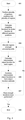
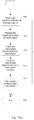
- the method begins in step 401.
- the n aperture positions: R 1 ...R n are partitioned into, or allocated amongst, m regions: S 1 ...S m . It is not necessary to partition the m regions so that each contains the same number of aperture positions, although doing so will lead to the fastest overall computational time.
- the m regions may contain each aperture position exactly once, i.e. the union of all m regions is exactly R 1 ...R n .
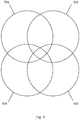
- the four aperture positions R 1 ...R 4 are divided into the two regions S 1 ,S 2 such that S 1 comprises R 1 and R 3 , whilst S 2 comprises aperture positions R 2 and R 4 .
- the aperture positions have been arbitrarily assigned to the regions.
- S 1 could comprise aperture positions R 1 and R 4 and no inter-relationship, such as a positional relationship, between regions and aperture positions is required.
- a weighting function w N (r-R) pertaining to the probe function at different aperture positions is calculated for each aperture position.
- a weighting function for each region w S ( r , S m ) is then calculated. The purpose of weighting is to cause the object function to be updated most strongly where the probe function has the largest amplitude i.e. carries more information.
- weighting factor is identical in definition and meaning to that found in the prior art, wherein the weighting factor is not a scalar variable but instead causes the object function to be updated most strongly where the probe function has largest amplitude.
- the weighting factor is essentially a normalised version of the probe function modified by ⁇ and l as shown above.
- w S r S m ⁇ R ⁇ S m w N r R where S m is the m th region.
- Equations 10-12 used to calculate aperture position weighting functions may be pre-calculated apriori. That is, the weighting functions may be determined in advance before the algorithm is desired to begin, thus saving computation time. In the first embodiment, Equations 13-15 may also be calculated in advance since the allocation of aperture positions amongst regions does not change during iterations of the algorithm.
- step 404 calculation of an intermediate object function for each region is assigned to a computation unit selected from amongst two or more computational units.
- intermediate object functions for each region will be repeatedly calculated. Whilst it may be more convenient to assign the calculation of an intermediate object function to a particular computational unit throughout the repeated iterations, the algorithm is not constrained in this way. That is, a first computational unit may calculate an intermediate object function for region S 1 during a first iteration and the calculation of an intermediate objection function for region S 1 during a second iteration may be performed by a second computational unit.
- computational unit is understood to mean a unit capable of performing independent calculations.
- an individual processor may represent a computational unit.
- a core of a multi-core processor may also represent a computational unit.
- a combination of cores in a multi-core processor or individual processor architectures may also be used.
- the computational units may be local to one-another i.e. connected to a bus interconnect, or may be remotely located and connected together by a wired or wireless communications medium, such as a network e.g. LAN or WAN network.
- each computational unit calculates an intermediate object function for a respective region.
- one or more computational units may calculate intermediate object functions for more than one region, depending upon a speed of execution of those computational units. It will be understood that it would be preferable to balance computing load across the computational units such that each computational unit finishes calculating intermediate objection functions for the one or more regions which it has been allocated at approximately the same time as the other computational units. This allows computational units having different speeds of execution to be used in combination.
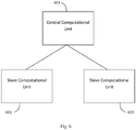
- FIG. 6 an arrangement is shown in Figure 6 comprising a central computational unit and two slave computational units 602, 603.
- the central computational unit is responsible for performing steps 402-404 of the method illustrated in Figure 4 , whilst each of the slave computational units 602, 603 calculates in parallel an intermediate object function for each region S 1 , S 2 of the described example.
- the designations "central” and “slave” do not imply any functional inter-dependency of the slave computational units 602, 603 on the central computational unit 601 or any performance hierarchy amongst the computational units.
- the central computational 601 unit may be identical to the slave computational units 602, 603.
- the central computation unit 601 may calculate an intermediate object function for one region and then calculate the combined object function using an intermediate objection calculated for the other region by one of the slave computational units 602, thus reducing the number of slave computational units required.
- step 405 computational units calculate in parallel intermediate object function guesses for all of the regions.
- the algorithm of WO 2005/106531 is applied which comprises starting with an object function guess and a known probe function and multiplying the two to form a guessed exit wave function in first plane; transforming that exit wave function to form an exit wave function in a second plane which is then corrected against measured intensities of the wave function in the second plane before inversely transforming the function to obtain an improved guess of the exit wave function in the first plane as explained with reference to steps 700-706 in particular.
- the reader is referred to Figure 3 and WO 2005/106531 .
- O g , j + 1 r O g , j r + w r ⁇ R P * r ⁇ R P r ⁇ R 2 + ⁇ ⁇ c , j r R ⁇ P r ⁇ R 2 P r ⁇ R 2 + ⁇ O g , j r
- an intermediate object function guess after j steps for aperture positions in the m th region ⁇ g,m,j is calculated in the same way as shown in Figure 3 for aperture positions in the m th region.
- the object function may equal unity at all points r , or may be randomly chosen at each point. Other initial values may also be used. Further, it will be noted that the initial object function for each region may be equal, or may be different in value.
- n/m is not an integer then a maximum value of j may be chosen appropriately.
- one region would necessarily comprise 3 aperture positions, whilst the other comprises 2 aperture positions.
- j would need to assume values of 1, 2 and 3, whilst for the other region j would need to assume values of 1 and 2. Therefore, the maximum value of j for each region should be chosen appropriately.
- step 405 intermediate object function guesses for all of the regions have been calculated.
- ⁇ g, 1,1 which is the intermediate object function guess for region 1
- ⁇ g, 2,1 for region 2.
- step 406 the intermediate object function guesses are combined to produce an object function guess O g,i for iteration i.
- step 407 it is determined whether the algorithm has been iterated a sufficient number of times.
- the algorithm may proceed for a pre-determined number of iterations, for example 1000, or alternatively can be terminated when the sum squared error (SSE) is sufficiently small.
- SSE sum squared error
- aperture positions are reassigned amongst regions during iterations of computation of the object function.
- the assignment of aperture positions does not have to be fixed for all iterations of the algorithm.
- the assignment of aperture positions may be changed after 50% of the iterations have been performed, or after every 10% or 25% of the iterations. More preferably, the aperture positions may be reassigned amongst the regions for every iteration of the algorithm.
- the assignment of aperture positions to regions may be performed on a predetermined or random basis.
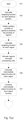
- the method begins in step 701 and in step 702 a weighting function for each aperture position is calculated.
- the weighting function for each aperture may be calculated in advance, as previously discussed.
- step 703 an initial partitioning of aperture positions amongst a plurality of regions is performed. The initial partitioning may be predetermined, in which case it would allow the calculation of initial weighting functions for each region to also be calculated in advance.
- step 705 calculation of intermediate objection functions is assigned amongst computational units, as in step 404 of the first embodiment.
- step 706 a first calculation of an intermediate object function is performed in parallel for each of the regions.
- the intermediate object functions are then combined in step 707 to form an object function for the first iteration.
- step 707 the aperture positions are reassigned amongst the regions.
- region S1 may comprise aperture positions R 1 and R 3 in the first iteration, which is then changed in step 708 to comprise aperture positions R 1 and R 4 in the second iteration.
- weighting functions for the regions are recalculated in step 709. If a predetermined reassignment of aperture positions to regions is utilised, the reassigned weighting functions may be calculated in advance and stored in memory for use in step 709.
- step 710 intermediate object functions are calculated for each of the regions, which are then combined in step 711 to form an object function guess for that iteration.
- step 712 it is determined whether enough iterations have been performed in the same way as in step 407 in the first embodiment.
- Figure 7 shows aperture positions being reassigned amongst regions for every iteration, the second embodiment is not constrained in this way and reassignment may be performed as desired.
- An advantage of the calculation of intermediate object functions for each region which are then combined to produce an object function for that iteration is that the a level of interdependency between intermediate object functions and a combined object function is introduced, reflecting the actual interdependence between regions in the real object. For example, if intermediate object functions for each region were calculated by 1000 iterations of equation 18, then the intermediate object functions for each region combined to produce a final object function, disparities, seen as, for example, a large difference between object functions for each region could exist. However, frequent combination of the intermediate object functions for to produce a combined object function reduces such differences. That is, the intermediate object functions are combined and the combination used in a subsequent iteration for calculating each intermediate object function, thus avoiding each intermediate function being created in isolation.
- embodiments of the present invention can be realised in the form of hardware, software or a combination of hardware and software. Any such software may be stored in the form of volatile or non-volatile storage such as, for example, a storage device like a ROM, whether erasable or rewritable or not, or in the form of memory such as, for example, RAM, memory chips, device or integrated circuits or on an optically or magnetically readable medium such as, for example, a CD, DVD, magnetic disk or magnetic tape. It will be appreciated that the storage devices and storage media are embodiments of machine-readable storage that are suitable for storing a program or programs that, when executed, implement embodiments of the present invention.
- embodiments provide a program comprising code for implementing a system or method as claimed in any preceding claim and a machine readable storage storing such a program. Still further, embodiments of the present invention may be conveyed electronically via any medium such as a communication signal carried over a wired or wireless connection and embodiments suitably encompass the same.
Landscapes
- Engineering & Computer Science (AREA)
- Health & Medical Sciences (AREA)
- Physics & Mathematics (AREA)
- Life Sciences & Earth Sciences (AREA)
- General Physics & Mathematics (AREA)
- Medical Informatics (AREA)
- Pathology (AREA)
- General Health & Medical Sciences (AREA)
- Theoretical Computer Science (AREA)
- Chemical & Material Sciences (AREA)
- Immunology (AREA)
- Algebra (AREA)
- Pure & Applied Mathematics (AREA)
- Analytical Chemistry (AREA)
- Biochemistry (AREA)
- Mathematical Physics (AREA)
- Mathematical Optimization (AREA)
- Mathematical Analysis (AREA)
- Computer Vision & Pattern Recognition (AREA)
- Biophysics (AREA)
- High Energy & Nuclear Physics (AREA)
- Crystallography & Structural Chemistry (AREA)
- Nuclear Medicine, Radiotherapy & Molecular Imaging (AREA)
- Optics & Photonics (AREA)
- Radiology & Medical Imaging (AREA)
- Biomedical Technology (AREA)
- Heart & Thoracic Surgery (AREA)
- Molecular Biology (AREA)
- Surgery (AREA)
- Animal Behavior & Ethology (AREA)
- Public Health (AREA)
- Veterinary Medicine (AREA)
- Analysing Materials By The Use Of Radiation (AREA)
- Investigating Or Analysing Materials By Optical Means (AREA)
Applications Claiming Priority (2)
| Application Number | Priority Date | Filing Date | Title |
|---|---|---|---|
| GBGB0817650.5A GB0817650D0 (en) | 2008-09-26 | 2008-09-26 | Improvements in the field of imaging |
| PCT/GB2009/051243 WO2010035033A1 (en) | 2008-09-26 | 2009-09-23 | Improvements in the field of imaging |
Publications (2)
| Publication Number | Publication Date |
|---|---|
| EP2338144A1 EP2338144A1 (en) | 2011-06-29 |
| EP2338144B1 true EP2338144B1 (en) | 2017-01-11 |
Family
ID=40019607
Family Applications (1)
| Application Number | Title | Priority Date | Filing Date |
|---|---|---|---|
| EP09737121.5A Active EP2338144B1 (en) | 2008-09-26 | 2009-09-23 | Method and apparatus for diffraction imaging |
Country Status (6)
| Country | Link |
|---|---|
| US (1) | US9202295B2 (enExample) |
| EP (1) | EP2338144B1 (enExample) |
| JP (1) | JP5575776B2 (enExample) |
| CN (1) | CN102227751B (enExample) |
| GB (1) | GB0817650D0 (enExample) |
| WO (1) | WO2010035033A1 (enExample) |
Families Citing this family (13)
| Publication number | Priority date | Publication date | Assignee | Title |
|---|---|---|---|---|
| GB0822149D0 (en) * | 2008-12-04 | 2009-01-14 | Univ Sheffield | Provision of image data |
| GB2481589B (en) | 2010-06-28 | 2014-06-11 | Phase Focus Ltd | Calibration of a probe in ptychography |
| US20120127297A1 (en) * | 2010-11-24 | 2012-05-24 | Baxi Vipul A | Digital microscopy with focus grading in zones distinguished for comparable image structures |
| GB201020516D0 (en) | 2010-12-03 | 2011-01-19 | Univ Sheffield | Improvements in providing image data |
| GB201107053D0 (en) | 2011-04-27 | 2011-06-08 | Univ Sheffield | Improvements in providing image data |
| GB201201140D0 (en) | 2012-01-24 | 2012-03-07 | Phase Focus Ltd | Method and apparatus for determining object characteristics |
| GB201207800D0 (en) * | 2012-05-03 | 2012-06-13 | Phase Focus Ltd | Improvements in providing image data |
| GB201215558D0 (en) * | 2012-08-31 | 2012-10-17 | Phase Focus Ltd | Improvements in phase retrieval |
| FR3001544B1 (fr) * | 2013-01-31 | 2015-02-27 | Commissariat Energie Atomique | Procede de reglage de la position relative d'un analyte par rapport a un faisceau lumineux |
| CN107924132B (zh) | 2014-08-28 | 2021-02-12 | Asml荷兰有限公司 | 检查设备、检查方法和制造方法 |
| GB201520426D0 (en) * | 2015-11-19 | 2016-01-06 | Phase Focus Ltd | Improved method |
| US11362481B2 (en) | 2020-05-01 | 2022-06-14 | Mesa Photonics, LLC | Method and apparatus for measuring optical pulses |
| US12367563B2 (en) * | 2021-03-25 | 2025-07-22 | Government Of The United States Of America, As Represented By The Secretary Of Commerce | Tomographic reconstruction apparatus and removing diffraction effects in a tomographic image |
Family Cites Families (6)
| Publication number | Priority date | Publication date | Assignee | Title |
|---|---|---|---|---|
| US6005916A (en) * | 1992-10-14 | 1999-12-21 | Techniscan, Inc. | Apparatus and method for imaging with wavefields using inverse scattering techniques |
| AU716800B2 (en) * | 1996-12-24 | 2000-03-09 | Xrt Limited | Phase retrieval in phase contrast imaging |
| US7295691B2 (en) * | 2002-05-15 | 2007-11-13 | Ge Medical Systems Global Technology Company, Llc | Computer aided diagnosis of an image set |
| GB0409572D0 (en) * | 2004-04-29 | 2004-06-02 | Univ Sheffield | High resolution imaging |
| KR101028354B1 (ko) * | 2007-03-20 | 2011-06-14 | 주식회사 메디슨 | 초음파 영상을 형성하는 초음파 시스템 및 방법 |
| GB0709796D0 (en) * | 2007-05-22 | 2007-06-27 | Phase Focus Ltd | Three dimensional imaging |
-
2008
- 2008-09-26 GB GBGB0817650.5A patent/GB0817650D0/en not_active Ceased
-
2009
- 2009-09-23 CN CN200980147396.XA patent/CN102227751B/zh not_active Expired - Fee Related
- 2009-09-23 US US13/121,064 patent/US9202295B2/en active Active
- 2009-09-23 WO PCT/GB2009/051243 patent/WO2010035033A1/en not_active Ceased
- 2009-09-23 JP JP2011528427A patent/JP5575776B2/ja not_active Expired - Fee Related
- 2009-09-23 EP EP09737121.5A patent/EP2338144B1/en active Active
Non-Patent Citations (1)
| Title |
|---|
| None * |
Also Published As
| Publication number | Publication date |
|---|---|
| US20110235862A1 (en) | 2011-09-29 |
| GB0817650D0 (en) | 2008-11-05 |
| CN102227751A (zh) | 2011-10-26 |
| WO2010035033A1 (en) | 2010-04-01 |
| JP2012510608A (ja) | 2012-05-10 |
| JP5575776B2 (ja) | 2014-08-20 |
| EP2338144A1 (en) | 2011-06-29 |
| US9202295B2 (en) | 2015-12-01 |
| CN102227751B (zh) | 2015-03-04 |
Similar Documents
| Publication | Publication Date | Title |
|---|---|---|
| EP2338144B1 (en) | Method and apparatus for diffraction imaging | |
| KR101810637B1 (ko) | 티코그래피에서 프로브의 보정 | |
| KR101455338B1 (ko) | 3차원 영상화 | |
| JP4926944B2 (ja) | 高分解能撮像 | |
| Whiting et al. | Source-finding for the australian square kilometre array pathfinder | |
| US9448160B2 (en) | Method and apparatus for providing image data for constructing an image of a region of a target object | |
| EP2890975B1 (en) | Estimation of background radiation from ptychography | |
| KR101896506B1 (ko) | 3차원 이미징 | |
| JP4594114B2 (ja) | 画像処理装置および屈折率分布測定装置 | |
| EP2227705B1 (en) | Method and apparatus for providing image data | |
| US12266162B2 (en) | Enhancing contrast sensitivity and resolution in a grating interferometer by machine learning | |
| JPH08110749A (ja) | 位相格子の設計システム | |
| EP2732274B1 (en) | Method and apparatus for position determination | |
| KR20250174455A (ko) | 다중 차수 모드 신호를 이용한 x-반사 분석 시스템 및 x-반사 분석 방법 | |
| US20180328867A1 (en) | Improved method ptychographic detector mapping | |
| HK1144897A (en) | Three dimensional imaging |
Legal Events
| Date | Code | Title | Description |
|---|---|---|---|
| PUAI | Public reference made under article 153(3) epc to a published international application that has entered the european phase |
Free format text: ORIGINAL CODE: 0009012 |
|
| 17P | Request for examination filed |
Effective date: 20110329 |
|
| AK | Designated contracting states |
Kind code of ref document: A1 Designated state(s): AT BE BG CH CY CZ DE DK EE ES FI FR GB GR HR HU IE IS IT LI LT LU LV MC MK MT NL NO PL PT RO SE SI SK SM TR |
|
| AX | Request for extension of the european patent |
Extension state: AL BA RS |
|
| DAX | Request for extension of the european patent (deleted) | ||
| DAX | Request for extension of the european patent (deleted) | ||
| 17Q | First examination report despatched |
Effective date: 20121205 |
|
| GRAP | Despatch of communication of intention to grant a patent |
Free format text: ORIGINAL CODE: EPIDOSNIGR1 |
|
| DAX | Request for extension of the european patent (deleted) | ||
| INTG | Intention to grant announced |
Effective date: 20160608 |
|
| GRAJ | Information related to disapproval of communication of intention to grant by the applicant or resumption of examination proceedings by the epo deleted |
Free format text: ORIGINAL CODE: EPIDOSDIGR1 |
|
| INTC | Intention to grant announced (deleted) | ||
| GRAR | Information related to intention to grant a patent recorded |
Free format text: ORIGINAL CODE: EPIDOSNIGR71 |
|
| GRAS | Grant fee paid |
Free format text: ORIGINAL CODE: EPIDOSNIGR3 |
|
| GRAA | (expected) grant |
Free format text: ORIGINAL CODE: 0009210 |
|
| INTG | Intention to grant announced |
Effective date: 20161121 |
|
| AK | Designated contracting states |
Kind code of ref document: B1 Designated state(s): AT BE BG CH CY CZ DE DK EE ES FI FR GB GR HR HU IE IS IT LI LT LU LV MC MK MT NL NO PL PT RO SE SI SK SM TR |
|
| REG | Reference to a national code |
Ref country code: GB Ref legal event code: FG4D |
|
| REG | Reference to a national code |
Ref country code: CH Ref legal event code: EP |
|
| REG | Reference to a national code |
Ref country code: AT Ref legal event code: REF Ref document number: 861895 Country of ref document: AT Kind code of ref document: T Effective date: 20170115 |
|
| REG | Reference to a national code |
Ref country code: IE Ref legal event code: FG4D |
|
| REG | Reference to a national code |
Ref country code: DE Ref legal event code: R096 Ref document number: 602009043698 Country of ref document: DE |
|
| REG | Reference to a national code |
Ref country code: CH Ref legal event code: NV Representative=s name: MICHELI AND CIE SA, CH |
|
| REG | Reference to a national code |
Ref country code: NL Ref legal event code: FP |
|
| REG | Reference to a national code |
Ref country code: LT Ref legal event code: MG4D |
|
| REG | Reference to a national code |
Ref country code: AT Ref legal event code: MK05 Ref document number: 861895 Country of ref document: AT Kind code of ref document: T Effective date: 20170111 |
|
| PG25 | Lapsed in a contracting state [announced via postgrant information from national office to epo] |
Ref country code: NO Free format text: LAPSE BECAUSE OF FAILURE TO SUBMIT A TRANSLATION OF THE DESCRIPTION OR TO PAY THE FEE WITHIN THE PRESCRIBED TIME-LIMIT Effective date: 20170411 Ref country code: IS Free format text: LAPSE BECAUSE OF FAILURE TO SUBMIT A TRANSLATION OF THE DESCRIPTION OR TO PAY THE FEE WITHIN THE PRESCRIBED TIME-LIMIT Effective date: 20170511 Ref country code: LT Free format text: LAPSE BECAUSE OF FAILURE TO SUBMIT A TRANSLATION OF THE DESCRIPTION OR TO PAY THE FEE WITHIN THE PRESCRIBED TIME-LIMIT Effective date: 20170111 Ref country code: HR Free format text: LAPSE BECAUSE OF FAILURE TO SUBMIT A TRANSLATION OF THE DESCRIPTION OR TO PAY THE FEE WITHIN THE PRESCRIBED TIME-LIMIT Effective date: 20170111 Ref country code: FI Free format text: LAPSE BECAUSE OF FAILURE TO SUBMIT A TRANSLATION OF THE DESCRIPTION OR TO PAY THE FEE WITHIN THE PRESCRIBED TIME-LIMIT Effective date: 20170111 Ref country code: GR Free format text: LAPSE BECAUSE OF FAILURE TO SUBMIT A TRANSLATION OF THE DESCRIPTION OR TO PAY THE FEE WITHIN THE PRESCRIBED TIME-LIMIT Effective date: 20170412 |
|
| PG25 | Lapsed in a contracting state [announced via postgrant information from national office to epo] |
Ref country code: PL Free format text: LAPSE BECAUSE OF FAILURE TO SUBMIT A TRANSLATION OF THE DESCRIPTION OR TO PAY THE FEE WITHIN THE PRESCRIBED TIME-LIMIT Effective date: 20170111 Ref country code: AT Free format text: LAPSE BECAUSE OF FAILURE TO SUBMIT A TRANSLATION OF THE DESCRIPTION OR TO PAY THE FEE WITHIN THE PRESCRIBED TIME-LIMIT Effective date: 20170111 Ref country code: ES Free format text: LAPSE BECAUSE OF FAILURE TO SUBMIT A TRANSLATION OF THE DESCRIPTION OR TO PAY THE FEE WITHIN THE PRESCRIBED TIME-LIMIT Effective date: 20170111 Ref country code: BG Free format text: LAPSE BECAUSE OF FAILURE TO SUBMIT A TRANSLATION OF THE DESCRIPTION OR TO PAY THE FEE WITHIN THE PRESCRIBED TIME-LIMIT Effective date: 20170411 Ref country code: PT Free format text: LAPSE BECAUSE OF FAILURE TO SUBMIT A TRANSLATION OF THE DESCRIPTION OR TO PAY THE FEE WITHIN THE PRESCRIBED TIME-LIMIT Effective date: 20170511 Ref country code: LV Free format text: LAPSE BECAUSE OF FAILURE TO SUBMIT A TRANSLATION OF THE DESCRIPTION OR TO PAY THE FEE WITHIN THE PRESCRIBED TIME-LIMIT Effective date: 20170111 Ref country code: SE Free format text: LAPSE BECAUSE OF FAILURE TO SUBMIT A TRANSLATION OF THE DESCRIPTION OR TO PAY THE FEE WITHIN THE PRESCRIBED TIME-LIMIT Effective date: 20170111 |
|
| REG | Reference to a national code |
Ref country code: FR Ref legal event code: PLFP Year of fee payment: 9 |
|
| REG | Reference to a national code |
Ref country code: DE Ref legal event code: R097 Ref document number: 602009043698 Country of ref document: DE |
|
| PG25 | Lapsed in a contracting state [announced via postgrant information from national office to epo] |
Ref country code: EE Free format text: LAPSE BECAUSE OF FAILURE TO SUBMIT A TRANSLATION OF THE DESCRIPTION OR TO PAY THE FEE WITHIN THE PRESCRIBED TIME-LIMIT Effective date: 20170111 Ref country code: RO Free format text: LAPSE BECAUSE OF FAILURE TO SUBMIT A TRANSLATION OF THE DESCRIPTION OR TO PAY THE FEE WITHIN THE PRESCRIBED TIME-LIMIT Effective date: 20170111 Ref country code: SK Free format text: LAPSE BECAUSE OF FAILURE TO SUBMIT A TRANSLATION OF THE DESCRIPTION OR TO PAY THE FEE WITHIN THE PRESCRIBED TIME-LIMIT Effective date: 20170111 Ref country code: IT Free format text: LAPSE BECAUSE OF FAILURE TO SUBMIT A TRANSLATION OF THE DESCRIPTION OR TO PAY THE FEE WITHIN THE PRESCRIBED TIME-LIMIT Effective date: 20170111 |
|
| PGFP | Annual fee paid to national office [announced via postgrant information from national office to epo] |
Ref country code: FR Payment date: 20170901 Year of fee payment: 9 |
|
| PLBE | No opposition filed within time limit |
Free format text: ORIGINAL CODE: 0009261 |
|
| STAA | Information on the status of an ep patent application or granted ep patent |
Free format text: STATUS: NO OPPOSITION FILED WITHIN TIME LIMIT |
|
| PG25 | Lapsed in a contracting state [announced via postgrant information from national office to epo] |
Ref country code: DK Free format text: LAPSE BECAUSE OF FAILURE TO SUBMIT A TRANSLATION OF THE DESCRIPTION OR TO PAY THE FEE WITHIN THE PRESCRIBED TIME-LIMIT Effective date: 20170111 Ref country code: SM Free format text: LAPSE BECAUSE OF FAILURE TO SUBMIT A TRANSLATION OF THE DESCRIPTION OR TO PAY THE FEE WITHIN THE PRESCRIBED TIME-LIMIT Effective date: 20170111 |
|
| 26N | No opposition filed |
Effective date: 20171012 |
|
| PG25 | Lapsed in a contracting state [announced via postgrant information from national office to epo] |
Ref country code: SI Free format text: LAPSE BECAUSE OF FAILURE TO SUBMIT A TRANSLATION OF THE DESCRIPTION OR TO PAY THE FEE WITHIN THE PRESCRIBED TIME-LIMIT Effective date: 20170111 |
|
| PG25 | Lapsed in a contracting state [announced via postgrant information from national office to epo] |
Ref country code: MC Free format text: LAPSE BECAUSE OF FAILURE TO SUBMIT A TRANSLATION OF THE DESCRIPTION OR TO PAY THE FEE WITHIN THE PRESCRIBED TIME-LIMIT Effective date: 20170111 |
|
| REG | Reference to a national code |
Ref country code: IE Ref legal event code: MM4A |
|
| REG | Reference to a national code |
Ref country code: BE Ref legal event code: MM Effective date: 20170930 |
|
| PG25 | Lapsed in a contracting state [announced via postgrant information from national office to epo] |
Ref country code: LU Free format text: LAPSE BECAUSE OF NON-PAYMENT OF DUE FEES Effective date: 20170923 |
|
| PG25 | Lapsed in a contracting state [announced via postgrant information from national office to epo] |
Ref country code: IE Free format text: LAPSE BECAUSE OF NON-PAYMENT OF DUE FEES Effective date: 20170923 |
|
| PG25 | Lapsed in a contracting state [announced via postgrant information from national office to epo] |
Ref country code: BE Free format text: LAPSE BECAUSE OF NON-PAYMENT OF DUE FEES Effective date: 20170930 |
|
| PG25 | Lapsed in a contracting state [announced via postgrant information from national office to epo] |
Ref country code: MT Free format text: LAPSE BECAUSE OF NON-PAYMENT OF DUE FEES Effective date: 20170923 |
|
| PG25 | Lapsed in a contracting state [announced via postgrant information from national office to epo] |
Ref country code: HU Free format text: LAPSE BECAUSE OF FAILURE TO SUBMIT A TRANSLATION OF THE DESCRIPTION OR TO PAY THE FEE WITHIN THE PRESCRIBED TIME-LIMIT; INVALID AB INITIO Effective date: 20090923 |
|
| PG25 | Lapsed in a contracting state [announced via postgrant information from national office to epo] |
Ref country code: FR Free format text: LAPSE BECAUSE OF NON-PAYMENT OF DUE FEES Effective date: 20180930 |
|
| PG25 | Lapsed in a contracting state [announced via postgrant information from national office to epo] |
Ref country code: CY Free format text: LAPSE BECAUSE OF NON-PAYMENT OF DUE FEES Effective date: 20170111 |
|
| PGFP | Annual fee paid to national office [announced via postgrant information from national office to epo] |
Ref country code: NL Payment date: 20190902 Year of fee payment: 11 Ref country code: DE Payment date: 20190904 Year of fee payment: 11 Ref country code: CZ Payment date: 20190827 Year of fee payment: 11 |
|
| PG25 | Lapsed in a contracting state [announced via postgrant information from national office to epo] |
Ref country code: MK Free format text: LAPSE BECAUSE OF FAILURE TO SUBMIT A TRANSLATION OF THE DESCRIPTION OR TO PAY THE FEE WITHIN THE PRESCRIBED TIME-LIMIT Effective date: 20170111 |
|
| PG25 | Lapsed in a contracting state [announced via postgrant information from national office to epo] |
Ref country code: TR Free format text: LAPSE BECAUSE OF FAILURE TO SUBMIT A TRANSLATION OF THE DESCRIPTION OR TO PAY THE FEE WITHIN THE PRESCRIBED TIME-LIMIT Effective date: 20170111 |
|
| PGFP | Annual fee paid to national office [announced via postgrant information from national office to epo] |
Ref country code: CH Payment date: 20191002 Year of fee payment: 11 |
|
| REG | Reference to a national code |
Ref country code: DE Ref legal event code: R119 Ref document number: 602009043698 Country of ref document: DE |
|
| PG25 | Lapsed in a contracting state [announced via postgrant information from national office to epo] |
Ref country code: CZ Free format text: LAPSE BECAUSE OF NON-PAYMENT OF DUE FEES Effective date: 20200923 |
|
| REG | Reference to a national code |
Ref country code: CH Ref legal event code: PL |
|
| REG | Reference to a national code |
Ref country code: NL Ref legal event code: MM Effective date: 20201001 |
|
| PG25 | Lapsed in a contracting state [announced via postgrant information from national office to epo] |
Ref country code: NL Free format text: LAPSE BECAUSE OF NON-PAYMENT OF DUE FEES Effective date: 20201001 |
|
| PG25 | Lapsed in a contracting state [announced via postgrant information from national office to epo] |
Ref country code: DE Free format text: LAPSE BECAUSE OF NON-PAYMENT OF DUE FEES Effective date: 20210401 |
|
| PG25 | Lapsed in a contracting state [announced via postgrant information from national office to epo] |
Ref country code: CH Free format text: LAPSE BECAUSE OF NON-PAYMENT OF DUE FEES Effective date: 20200930 Ref country code: LI Free format text: LAPSE BECAUSE OF NON-PAYMENT OF DUE FEES Effective date: 20200930 |
|
| REG | Reference to a national code |
Ref country code: GB Ref legal event code: 732E Free format text: REGISTERED BETWEEN 20241205 AND 20241211 |
|
| PGFP | Annual fee paid to national office [announced via postgrant information from national office to epo] |
Ref country code: GB Payment date: 20250923 Year of fee payment: 17 |