EP2337841B1 - Elektrodeneinrichtung, generatoreinrichtung und verfahren zur stromerzeugung durch membranpotential-ableitung - Google Patents
Elektrodeneinrichtung, generatoreinrichtung und verfahren zur stromerzeugung durch membranpotential-ableitung Download PDFInfo
- Publication number
- EP2337841B1 EP2337841B1 EP09778365A EP09778365A EP2337841B1 EP 2337841 B1 EP2337841 B1 EP 2337841B1 EP 09778365 A EP09778365 A EP 09778365A EP 09778365 A EP09778365 A EP 09778365A EP 2337841 B1 EP2337841 B1 EP 2337841B1
- Authority
- EP
- European Patent Office
- Prior art keywords
- electrode
- cells
- electrodes
- layer
- cell
- Prior art date
- Legal status (The legal status is an assumption and is not a legal conclusion. Google has not performed a legal analysis and makes no representation as to the accuracy of the status listed.)
- Not-in-force
Links
Images

Classifications
-
- C—CHEMISTRY; METALLURGY
- C12—BIOCHEMISTRY; BEER; SPIRITS; WINE; VINEGAR; MICROBIOLOGY; ENZYMOLOGY; MUTATION OR GENETIC ENGINEERING
- C12M—APPARATUS FOR ENZYMOLOGY OR MICROBIOLOGY; APPARATUS FOR CULTURING MICROORGANISMS FOR PRODUCING BIOMASS, FOR GROWING CELLS OR FOR OBTAINING FERMENTATION OR METABOLIC PRODUCTS, i.e. BIOREACTORS OR FERMENTERS
- C12M1/00—Apparatus for enzymology or microbiology
- C12M1/34—Measuring or testing with condition measuring or sensing means, e.g. colony counters
-
- G—PHYSICS
- G01—MEASURING; TESTING
- G01N—INVESTIGATING OR ANALYSING MATERIALS BY DETERMINING THEIR CHEMICAL OR PHYSICAL PROPERTIES
- G01N33/00—Investigating or analysing materials by specific methods not covered by groups G01N1/00 - G01N31/00
- G01N33/48—Biological material, e.g. blood, urine; Haemocytometers
- G01N33/483—Physical analysis of biological material
- G01N33/487—Physical analysis of biological material of liquid biological material
- G01N33/48707—Physical analysis of biological material of liquid biological material by electrical means
- G01N33/48728—Investigating individual cells, e.g. by patch clamp, voltage clamp
-
- C—CHEMISTRY; METALLURGY
- C12—BIOCHEMISTRY; BEER; SPIRITS; WINE; VINEGAR; MICROBIOLOGY; ENZYMOLOGY; MUTATION OR GENETIC ENGINEERING
- C12M—APPARATUS FOR ENZYMOLOGY OR MICROBIOLOGY; APPARATUS FOR CULTURING MICROORGANISMS FOR PRODUCING BIOMASS, FOR GROWING CELLS OR FOR OBTAINING FERMENTATION OR METABOLIC PRODUCTS, i.e. BIOREACTORS OR FERMENTERS
- C12M1/00—Apparatus for enzymology or microbiology
-
- C—CHEMISTRY; METALLURGY
- C12—BIOCHEMISTRY; BEER; SPIRITS; WINE; VINEGAR; MICROBIOLOGY; ENZYMOLOGY; MUTATION OR GENETIC ENGINEERING
- C12M—APPARATUS FOR ENZYMOLOGY OR MICROBIOLOGY; APPARATUS FOR CULTURING MICROORGANISMS FOR PRODUCING BIOMASS, FOR GROWING CELLS OR FOR OBTAINING FERMENTATION OR METABOLIC PRODUCTS, i.e. BIOREACTORS OR FERMENTERS
- C12M1/00—Apparatus for enzymology or microbiology
- C12M1/42—Apparatus for the treatment of microorganisms or enzymes with electrical or wave energy, e.g. magnetism, sonic waves
-
- C—CHEMISTRY; METALLURGY
- C12—BIOCHEMISTRY; BEER; SPIRITS; WINE; VINEGAR; MICROBIOLOGY; ENZYMOLOGY; MUTATION OR GENETIC ENGINEERING
- C12M—APPARATUS FOR ENZYMOLOGY OR MICROBIOLOGY; APPARATUS FOR CULTURING MICROORGANISMS FOR PRODUCING BIOMASS, FOR GROWING CELLS OR FOR OBTAINING FERMENTATION OR METABOLIC PRODUCTS, i.e. BIOREACTORS OR FERMENTERS
- C12M3/00—Tissue, human, animal or plant cell, or virus culture apparatus
Definitions
- the invention relates to an electrode device which is designed to derive a membrane potential on at least one membrane-enveloped cell, in particular on a plurality of cells. Furthermore, the invention relates to a generator device which is equipped with the electrode device and adapted to generate electricity by deriving a membrane potential. Finally, the invention also relates to a method for generating electricity by deriving a membrane potential on at least one biological or synthetic cell. Applications of the invention are in the generation of electrical power for operating an electrical device and / or for charging a battery.
- the main concept of energy conversion using biological materials is based on the generation and combustion of biogas (mainly methane) or hydrogen (see J. Niessen et al. in Letters in Applied Microbiology, Vol. 41, 2005, pp. 286-290 ).
- the energy conversion out Biogas is disadvantageous because of the carbon dioxide produced during combustion and because of the occurrence of by-products, such as ammonia and hydrogen sulfide, which require elaborate purification steps.
- Other concepts are based on so-called biofuel cells, which are operated on the basis of an enzymatic degradation of macromolecules, such as sugar (see RF Service in "Science", Vol. 296, 2002, p. 1223 ). Again, these concepts have found no routine application, as the energy yield, the limited stability of the energy conversion and the high cost have proven to be disadvantageous.
- the cell membranes contain membrane parts designed for ion transport. These membrane parts, which include ion pumps and ion channels, will be referred to as ion pumps for short. Ion transport generates an electrochemical gradient across the cell membrane that forms the membrane potential.
- the membrane potential can be measured by electrophysiological methods (see for example E. Neher in “Science”, Vol. 256, 1992, pp. 498-502 ; W. Baumgartner et al. in "Biophysical Journal", Vol. 77, 1999, pp. 1980-1991 ; DE 101 08 968 A1 ; or DE 198 27 957 A1 ).
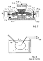
- FIG. 8 The conventional electrophysiological measurement of membrane potential is schematically shown in FIG. 8 illustrated.
- a biological cell 1 ' is held with a pipette 10' in a culture medium 3 '.
- An anode 22 ' is immersed in the culture medium 3' and a cathode 21 'protrudes from the culture medium 3' into the interior of the cell 1 '.
- the anode 22 'and the cathode 21' are connected to an amplifier 30 ', with which the electrical signals derived Represent membrane potential, strengthened and prepared for further processing.
- the pipette 10 ' forms a cell receptacle, which, for example, is known from practice for the measurement of adherent cells, may be replaced by a substrate in the culture medium 3' on which the cell 1 'is arranged.
- the application of the conventional measuring device according to FIG. 8 is limited to measuring the membrane potential on individual cells. Since glass electrodes or metal-filled glass capillaries with tip diameters above 100 nm have hitherto been used as the cathode 21 ', problems result from a low tolerance of the cell 1' with respect to the cathode 21 'and a restriction to high measuring resistances. For example, electrodes with diameters above 10 ⁇ m can be tolerated by the cell only for a few hours.
- the measuring resistor is of the order of 100 M ⁇ , limiting the derived currents to minimum charge quantities.
- the object of the invention is to provide an improved electrode device which is suitable for membrane potential dissipation on membrane-coated cells and with the disadvantages of conventional techniques can be overcome.
- the object of the invention is furthermore to provide an improved generator device for generating electric power using biological materials, which overcomes the limitations of conventional generator devices and is characterized in particular by an increased service life, improved operational stability and reduced costs.
- the object of the invention is also to provide an improved method of energy conversion using biological materials, in particular for power generation, with the disadvantages of conventional renewable energy sources based on biological materials are avoided.
- an electrode device which is adapted for membrane potential discharge on membrane-coated cells and has a cell receptacle for adherent fixing of the cells and an electrode carrier having at least two electrodes of a first polarity, as protrusions formed over a surface of the electrode carrier and are electrically insulated relative to the surface of the electrode carrier.
- the electrode carrier according to the invention is formed so that when the cell receptacle carries the cells, the electrodes protrude into the cells simultaneously.
- the object is achieved by a generator device, which is for generating electrical current is established by the derivation of a membrane potential to cells and having an electrode device according to the above-mentioned first aspect, wherein on the surface of the cell receiving at least one cell, but preferably a plurality of cells is arranged.
- the object is achieved by a method for generating electric current by deriving a membrane potential to cells, which are arranged on the cell receptacle of the electrode device according to the above-mentioned first aspect in an adherent state, wherein the electric current with the electrodes and at least one counter electrode which is in direct electrical contact (touch) or, e.g. B. via a conductive medium, is in indirect electrical contact.
- an electrode arrangement is realized by the electrode carrier with the at least two electrodes, which has an increased stability of the electrodes and a simplified structure compared to conventional techniques.
- the multi-electrode electrode carrier allows the electrodes to be brought into direct electrical contact with the interior of at least one, but preferably a plurality of cells simultaneously and in particular electrically in parallel.
- the inventors have realized that by using the electrode carrier the membrane potential derivative can be scaled and thus the limitation to impractically low currents can be overcome. Furthermore, it is possible to set the current strength and / or the voltage of the generator device as a function of the conditions of the specific application by a parallel connection, a series connection or a combination of parallel and series connection.
- the invention has the following further advantages.
- the generator device according to the invention represents a renewable power source that is suitable as a macroscopic power supply in consumer circuits.
- the contacting of the cells takes place by self-integration of the cells at the electrodes of the electrode device.
- the electrode carrier has a nano- or microstructured surface through the electrode projections. The structure promotes the binding of the cells to the projections and thus the uptake of the electrodes into the cells and their contacting.
- Further advantages of the invention are the environmental compatibility of the generator device and the sustainability and climate neutrality of power generation.
- cell generally refers to a membrane-enveloped fluid region, the membrane being used to create the membrane potential between the fluid region inside the cell and a fluid, for example a culture medium, in the environment of the cell Cell is set up.
- the membrane contains proteins which form ion pumps (and ion channels) and are adapted for ion transport between the outside environment of the cell and the interior of the cell.
- the generator device is thus based on the use of biological materials in that the electrochemical membrane potential of cultured biological cells, which naturally contain ion pumps, or of synthetic lipid vesicles ("phantom cells") containing ion pumps integrated in the membrane, which measures the potential between the cells Build up the interior and the external environment of the vesicles, used for power generation.
- Biological cells have the advantage that the ability to form a membrane potential is naturally given by the existing ion pumps.
- biological cells eukaryotic cells or prokaryotic cells such.
- bacteria eukaryotic cells are preferred because of their larger size.
- the ion pumps in the membrane of the vesicles are known per se with biotechnological Method, preferably provided using genetically modified biological cells.
- the lifetime of the cells can be increased by using immortalized cells in which proteins are continuously regenerated, with their folding being controlled and adapted to variable conditions.
- Synthetic cells have the advantage that the lifetime of the cells can be increased compared to living biological cells and less stringent environmental requirements are imposed than is the case in the culture conditions of biological cells.
- the electrodes are formed as projections, which are electrically insulated relative to the surface of the cell receptacle.
- each of the electrodes has an insulator jacket which surrounds the electrode except for its free end. The insulator jacket extends in the longitudinal direction of the electrode and leaves the tip of the electrode exposed.
- At least one counter electrode of a second, opposite to the said electrodes opposite polarity is provided, wherein the at least one counter electrode is formed on the surface of the electrode carrier and / or on a separate from the electrode carrier counter electrode carrier.
- the at least one counter electrode may comprise a uniform electrically conductive layer or a plurality of electrically conductive electrode layer segments on the electrode carrier and / or the counterelectrode carrier.
- the uniform electrically conductive layer has the advantage that with a single counter electrode, the electrical contact with a plurality of cells, for example with a cell monolayer on the surface of the electrode carrier can be produced.
- the electrically conductive electrode layer segments may be configured to be controllable, e.g. B. are individually connected to a consumer circuit.
- the individually controllable electrode layer segments have advantages if a non-closed layer of the cells is provided on the surface of the carrier device.
- the electrode layer segments may have advantages in avoiding short circuits between the electrode layer segments and the electrodes of opposite polarity.
- the counter electrode may comprise an electrode rod which is immersed in an ion-containing medium in the vicinity of the cells.
- At least one of the electrode carrier and the counterelectrode carrier constitutes the cell receptacle.
- the cells whose membrane potential is dissipated can be adhered directly to the electrode carrier and / or the counterelectrode carrier.
- a negative or a positive potential may form in the interior of the cell relative to the external environment of the cell.
- the electrodes which protrude into the interior of the cells and the at least one counter electrode which is in direct or indirect electrical contact with the outside of the cell have generally opposite relative to each other Polarities.
- the electrodes form cathodes, while the at least one counterelectrode forms at least one anode.
- the electrode forms a cathode while the counter electrode forms an anode.
- the electrode carrier has a multilayer structure with an electrode layer, an insulator layer and a counterelectrode layer, wherein the electrodes protrude electrically insulated from the electrode layer through the insulator layer and the counterelectrode layer over the surface of the counterelectrode layer.
- this creates a particularly compact construction of the electrode carrier with all the electrodes and counterelectrodes.
- the contact between the electrodes and the at least one counterelectrode on the one hand and the cells on the other hand can be improved if at least one of the electrodes and / or counterelectrodes carries a coating which enhances the interaction between the electrode surface and the cell membrane.
- the conductivity between the cells and the electrodes and / or counter electrodes can be increased and the contact resistance can be reduced by the coating.
- the electrodes protruding on the surface of the electrode carrier carry a coating which activates endocytosis of the membrane.
- the endocytosis-activating coating has the advantage of facilitating the uptake of the electrodes into the interior of the cells.
- the endocytosis-activating coating in biological cells causes them to actively pick up the electrodes due to their natural cell movement, so that they form the contact in the interior of the cells.
- the at least a counter electrode carry an adhesion and / or conductivity-enhancing coating.
- this increases the adherent binding of the cell to the surface of the electrode or counterelectrode carrier.
- a closure of possibly occurring holes in a layer with a multiplicity of cells is stimulated.
- the inventive use of the membrane potential for power generation can be facilitated if the electrodes which protrude into the interior of the cells, has a smaller diameter than is the case with the conventional electrophysiological measurements.
- the diameter of the electrodes is less than 10 ⁇ m, more preferably less than 1 ⁇ m, such as less than 500 nm, in particular less than 100 nm, such as less than 10 nm, for example 2 nm or even 1 nm. Electrodes with such a small diameter are advantageously more easily tolerated by cells, especially biological cells. Thus, the long-term stability of power generation is improved. Furthermore, the resistance between each of the electrodes and the interior of the cells can be reduced.
- the electrodes may comprise an array of sub-micron diameter conductors (so-called nanowires) which improve the tapping of the voltage potential formed between the internal spaces and the external environment of the cells.
- the free electrode surface of the electrodes for example a tip of the electrode, has a distance from the surface of the electrode carrier which is at least 10 nm, preferably at least 100 nm, particularly preferably at least 1 ⁇ m, for example 50 ⁇ m or more, up to the mm range.
- This allows a secure positioning of the electrodes inside the cells. It can In particular, synthetic cells with a diameter up to the mm range can be securely contacted.
- two or more electrodes may be provided.
- z. B. at least ten, especially at least one hundred, z. B. at least 1000, such as. B. 10,000 or more electrodes.
- the electrodes are preferably connected to one another electrically.
- the electrodes particularly preferably form a 1- or 2-dimensional array of electrode tips which protrude from the surface of the electrode carrier and are electrically isolated from the at least one counterelectrode of opposite polarity.
- the membrane potential at all cells can be dissipated simultaneously.
- the cells in particular biological cells and / or synthetic vesicles, form a closed cell layer on the surface of the electrode carrier.
- the current derivatives of the membrane potentials of the individual cells are connected in parallel and thus advantageously increase the output current of the generator device according to the invention.
- a total power of 7 ⁇ W can be generated.
- the performance is comparable to the performance of solar cells of the same area.
- the generator device according to the invention can be operated completely independently of light. It requires less space and is subject to less restrictive operating conditions than a solar cell battery.
- the electrodes and the at least one counter electrode are adapted to be connected directly to a load circuit.
- the consumption advantageously has an immediate effect on the derivation of the membrane potential and the activity of the ion pumps.
- a connection can be provided with an accumulator device.
- the accumulator device is generally an electrical energy store, such as an electrochemical accumulator or a capacitor with a predetermined capacity, the actual design of which is selected as a function of the requirements of the specific application of the generator device.
- the accumulator device can be charged with the electricity generated according to the invention, it has the advantage that a consumer circuit is not directly connected to the electrodes, but is decoupled from them. Thus, disturbing repercussions of the consumer circuit, such as rapid load changes to the at least one cell in the generator means, can be avoided.
- a cultivation device is provided.
- the culture means is arranged to supply an ion-containing medium to the environment of the cells.
- the ion-containing medium is a liquid (eg, a culture medium) which supplies and regenerates the cells.
- the culture means comprises a reservoir for the culture medium as known from cell biology and a supply means for supplying the culture medium to the cells on the cell uptake. With the ion-containing medium, ions are continuously supplied to the environment of the cells, which are transported into the interior of the cells under the action of the ion pumps and thus build up the membrane potential.
- the cells contain at least one ion-binding substance in their interior, advantages for the life or stability of the cells may result.
- the ion-binding substance acts as a buffer in the interior of the cell.
- the ions transported through the membrane into the interior are collected by the ion-binding substance.
- the ion-binding substance includes, for example, ethylenediaminetetraacetic acid (EDTA), ascorbic acid (vitamin C) or glutathione.
- Preferred applications of the generator device according to the invention are in the power supply of electrical equipment with a relatively low electrical power, such as body implants, for example, pacemakers or hearing aids, but by the scalability of the generator device and devices with increased power consumption, such as household appliances can be supplied.
- body implants for example, pacemakers or hearing aids
- the generator device can be supplied directly with nutrients of the body, in particular from the tissue adjacent to an implant.
- Embodiments of the invention will now be described in terms of preferred features of the electrode means, the generator means and the method of operation thereof.
- Cell biological and electrochemical considerations such as the generation of membrane potential, the provision of culture conditions for adherent cells, the integration of ion pump (and channel) forming proteins into lipid membranes are not described here because they are known per se from cell biology and electrochemistry.
- the implementation of the invention is not limited to the types of biological or synthetic cells exemplified, but is suitably possible with all membrane-coated cells which are suitable for forming a membrane potential by transporting charged particles, in particular ions, through the membrane.
- Embodiments of the invention will be described by way of example with reference to power generation with two cells (FIG. FIGS. 1 to 3 ) or with more cells ( Figures 3 . 4 ). It is emphasized that the implementation of the invention is not limited to the examples described.
- the design of the generator device according to the invention, in particular its size and the means for supplying the cells, can be selected and adapted depending on the specific conditions of application of the invention.
- the electrodes on the surface of the electrode carrier are cathode and the at least one counterelectrode is an anode.
- the power generation takes place by derivation of membrane potentials, which are formed by the transport of ions into and / or from the interior of the cell.
- the membrane potential is z. B. is formed by a Na + -K + pump for three sodium ions pumped from the cell, only two potassium ions pumped into the cell.
- the implementation of the invention is accordingly possible with reversed polarity, in that the electrodes constitute the cathode and the at least one counterelectrode represents at least one anode.
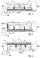
- the generator device 200 comprises an electrode device 100 with a cell receptacle 10, which simultaneously forms the electrode carrier 20 and the counterelectrode carrier 30.
- the electrode carrier 20 comprises cathodes 21 as electrodes and an anode 22 as counterelectrode, on the surface of which cells 1 are arranged.
- the electrode device 100 is arranged with the cells 1 in a generator vessel 11, which contains an ion-containing medium 3 and with a cultivation device (in FIG. 1 not shown) may be connected.
- the electrode carrier 20 comprises a multilayer structure comprising a lower cathode layer 23, a middle insulator layer 24 and an upper anode layer 25, which at the same time forms the anode 22 and the surface for receiving the cells 1 in an adherent state.
- the outside of the membrane sheath 2 of the cell 1 has a direct electrical contact with the anode 23.
- the cathode layer 23 and the anode layer 25 are connected via electrical lines 41 to a load circuit 40 and / or an accumulator device (shown schematically).
- the fabrication of the layer structure of the cathode layer 23, the insulator layer 24 and the anode layer 25 will be described in more detail below with reference to FIGS FIGS. 4 and 5 described.
- the cathodes 21 protrude as tip-shaped protrusions from the cathode layer 23 through the anode layer 25 via the surface thereof into the generator vessel 11.
- the insulator layer 24 forms at each cathode 21 an insulator jacket 26 which surrounds the cathode 21 .
- the insulator jacket 26 extends in the longitudinal direction of the cathode 21 with a length which is at least equal to the thickness of the anode layer 25.
- the insulator sheath 26 extends as in FIG figure 1 represented over the surface of the anode layer 25 in the generator vessel 11 in order to improve the electrical insulation of the cathode 21 and the anode 22.
- the axial length of the insulator jacket 26 is selected so that a free end of the cathode 21 (cathode tip) in the generator vessel 11 is exposed.
- the cathodes 21 preferably comprise carbon, an inert metal such as e.g. As gold, or a doped semiconductor.
- the insulator layer 24 is formed by a ceramic layer, such as a metal oxide.
- the anode 22 is also preferably made of carbon, an inert metal or a doped semiconductor.
- the cells 1 with the membrane sheaths 2 are arranged on the surface of the anode layer 25 in such a way that the cathodes 21 with the insulator sheath 26 protrude into the interior of the cells 1.
- Each cathode tip is in direct electrical contact with the internal cell material, as in the case of a biological cell with the cell plasma or in the case of a synthetic cell with an internal medium of a vesicle.
- the cells 1 include, for example, living biological cells, such as epithelial cells or fibroblasts.
- the ion-containing medium 3 in the generator vessel 11 comprises a culture medium, such as a physiological saline solution, from which ions are transported through the membrane sheaths 2 into the interior of the cells 1.
- the membrane potential formed during this process is dissipated via the electrical leads 41. As soon as the ion pumps in the membrane sheaths 2 detect a charge balance between the interior of the cells 1 and the external medium, a further ion transport takes place into the interior of the cells 1.
- Biological cells that can be used to generate electricity include, for example, cardiac myocytes (HL1), epithelial cells or fibroblasts (eg REF-52). Fibroblasts have the particular advantage of forming stable, long lasting and self-repairing closed monolayers on solid surfaces, particularly on the surface of the anode layer 25 or an insulator layer 24 (see below).
- cardiac myocytes HL1
- epithelial cells eg REF-52
- Fibroblasts have the particular advantage of forming stable, long lasting and self-repairing closed monolayers on solid surfaces, particularly on the surface of the anode layer 25 or an insulator layer 24 (see below).
- NRK cells normal rat kidney cells, in particular NRK fibroblasts
- NRK fibroblasts are described, for example, in the publication of JJ Torres in "Am J. Physiol Cell Physiol.” (Vol. 287, 2004, p. C851-C865 ).
- NRK cells form stable monolayers, wherein the individual cells are connected via membrane channels (so-called "gap junctions") (see FIG. 1C of said publication).
- the membrane channels provide for an efficient electrical connection of the cells and thus for a significant increase in the capacity of the generator device according to the invention, in particular as a function of the electrode density. With simultaneous lowering of the electrode density, which can lead to a higher survival rate of the cells, consistently high or even increased capacities are realized, since not directly pierced cells are coupled to the system.
- the biological cells may be manipulated by per se known biomolecular methods to form, for example, stable cell clones characterized by overexpression of certain ion channels and pumps to increase electrical performance.
- stable cell clones characterized by overexpression of certain ion channels and pumps to increase electrical performance.
- connexin molecules building blocks of the above gap junction channels
- the electrical coupling / capacity in any cells or even vesicles can be artificially increased.
- Synthetic vesicles with single or multi-layer membrane sheaths can be prepared by standard techniques known in the art (see, for example A. Moscho et al. in "Proc Natl. Acad Sci.”, Vol. 93, 1996, pp. 11443-11447 ). It can vesicles with a diameter z. B. be provided in the range of 1 micron to 50 microns or above 50 microns (so-called “giant vesicles", giant vesicles). The self-integration of the cells on the electrode device is assisted by biofunctionalization of the electrode surfaces with an adhesion-enhancing coating and / or an endocytosis-activating coating.
- FIG. 2 In a modified embodiment of the generator device 200 is schematically illustrated, in which the cell holder 10 or the electrode carrier 20 of the electrode device 100 has only the cathode layer 23 with the cathodes 21 and the insulator layer 24. As the counter electrode (anode) is immersed in the medium 3 in the generator vessel 11 electrode rod 27 is provided.
- FIG. 2 schematically illustrates a further modified embodiment of the generator device 200, in which the cell receptacle 10 comprises the anode layer 25 with the anode 22, while the electrode carrier 20 with the cathodes 21 is arranged at a distance from the cell receptacle 10.
- the electrode carrier 20 is arranged in the medium 3 in the generator vessel 11 in such a way that the cathodes 21 protruding from the electrode carrier 20 towards the cell receptacle 10 project into the interior of the cells 1 arranged on the cell receptacle 10.
- the electrode carrier 20 comprises the cathode layer 23 and the insulator layer 24 with the insulator jacket 26 for each cathode 21.
- the cathodes 21 and the cathode layer 23 are electrically insulated from the medium 3 in the generator vessel 11 and the anode 22.
- the anode layer 25 and the cathode layer 23 are connected via electrical lines 41 to the load circuit 40 and / or the accumulator device.
- FIGS. 1 to 3 can be further modified as follows. First, more than two cathodes may be provided (see below, FIGS. 4, 5 ). Furthermore, the variants of the FIGS. 1 to 3 can be combined by cathodes are integrated into two separate electrode carrier and protrude from two sides into the cells.
- the multi-layer structure of the cathode, insulator and anode layers may have further layers, for. B. a carrier layer with which the multilayer structure is mechanically stabilized and z. B. made of plastic is formed (see FIG. 6B ).
- FIGS. 4 and 5 show a modified embodiment of the invention, in which an array of cathodes is provided, in a schematic sectional view (FIG. FIG. 4 , Detail) and in schematic perspective view ( FIG. 5 ).
- This embodiment is particularly suitable for power generation by deriving the membrane potential at cell layers, in particular a monolayer. For clarity, are in the FIGS. 4 and 5 but shown only single cells.
- FIGS. 4 and 5 includes the electrode carrier 20, as above with reference to FIG. 1 describes a multilayer structure of the cathode layer 23, the insulator layer 24 and the anode layer 25.
- the cathode layer 23 and the anode layer 25 are connected via electrical lines 41 to the load circuit 40 and / or the accumulator device. It can be a current measuring device 42 be provided, the example in FIG. 5 is shown.
- the cathodes 21 protrude, each sheathed with an insulator jacket 26, through the anode layer 25 into the generator vessel 11.
- the generator vessel 11 is filled with an ion-containing medium 3 which is supplied and removed by a culturing device 50 (shown schematically) via liquid lines 51 becomes.
- the cultivation device 50 may further comprise a temperature control device (not shown) with which the temperature of the generator device, for. B. to a physiological temperature of the cells, is adjustable.
- an adhesion enhancing (and conductivity enhancing) coating 28 comprising, for example, fibronectin, laminin, peptides, for example RDG sequences, or collagen.
- the exposed tips of the cathodes 21 carry an endocytosis-activating coating 29 which, for example, comprises molecules with which membrane binding forces of the cell are locally variable, such as lectins or SNARE (Soluble N-ethylmaleimide-sensitive-factor Attachment Receptor -Protein).
- the size of the surface of the anode layer 25 is selected as a function of the desired power of the generator device 200 and thus the desired number of cells 1 that contribute to the generation of electricity.
- the electrode device 100 can be provided, for example, for accommodating more than 10, 100, 1,000, 10,000 or more cells.
- the number of cathodes 21 may be 10, 100, 1,000, 10,000 or more.
- the surface of the anode layer 25 has a size of at least 1 cm 2 .
- the production of the electrode device 100 takes place according to a method with which electrodes with a length of a few micrometers and a diameter of less than 100 nm can be produced.
- DRIE Deep Reactive Ion Etching
- the cathode diameters are limited to a few 100 nm. Smaller structures can be created when the DRIE process is combined with electron beam patterning or nanospheres or block copolymer micelle lithography.
- the cathodes can be constructed by deposition techniques (bottom-up process), wherein a liquid-solid deposition (VLS process) or a metal halide reduction (MHR process) is provided.
- VLS process liquid-solid deposition
- MHR process metal halide reduction
- metallic nuclei forming a eutectic layer on a silicon wafer are used to grow silicon nanowires by physical vapor deposition (see L. Schubert et al. in Applied Physics Letters, Vol. 84, 2004, pp. 4968-4970 ).
- the cathodes can be made using metal halides are formed as germs (see P. Yang et al. in "JACS", Vol. 129, 2007, p. 7228-7229 ).
- the cathodes 21 may be formed by carbon nanotubes growing in a carbon-rich atmosphere of nickel- or iron-based nuclei (see CJ Lee et al. in "Chemical Physics Letters", Vol. 323, 2000, pp. 554-559 ).
- the electrode device can also be produced by applying a structuring method which is described in US Pat WO 2007/096082 A1 is described.
- a structuring method which is described in US Pat WO 2007/096082 A1 is described.
- the following multi-step method is preferably provided.
- a first step a surface of a polymer material with a regularly or irregularly distributed thread arrangement is produced by melting and then drawing the threads by means of a roller, as shown in FIG WO 2007/096082 A1 is described.
- This publication is hereby incorporated by reference into the present specification.
- FIG. 6A is a molding (die) for the production of the electrode device with such a structured polymer surface 12.1 shown by way of example.
- the structured surface 12.1 is then coated with layers of gold and SiO 2 and / or Si 3 N 4 and patterned to form the layer and electrode structure described here.
- the coating comprises, for example, a physical vapor deposition.
- the thickness of the layers is selected as a function of the specific conditions of use, in particular taking into account the electrical conductivity of the gold layer and the insulating properties of the SiO 2 and / or Si 3 N 4 layer.
- the insulating SiO 2 and / or Si 3 N 4 layer of which Electrode tips removed by wet chemical etching or reactive ion etching.
- biofunctionalization of the surface follows using techniques known in the art.
- FIG. 6B shows a photographic representation of a portion of an electrode device according to the invention with a single cathode 21 (marked graphically), which was recorded with a scanning electron microscope (SEM).
- the layer structure comprises, on a carrier layer 12, the cathode layer 23 and the anode layer 25, each made of gold, which are separated by the insulator layer 24 made of SiO 2 .
- the cathodes 21 grow as nanowires through holes in the anode layer 25, using the cathode layer 23 as a seed.
- the cathode 21 extends perpendicular to the surface of the anode layer 25.
- FIG. 7 11 illustrates further details of a generator vessel 11 which is provided for accommodating the generator device 200 according to the invention (schematically illustrated without electrical lines) and connected to the cultivation device 50 (illustrated schematically).
- the generator device 200 may be positioned in the generator vessel 11 and / or integrated in the bottom of the generator vessel 11.
- the generator vessel 11 is formed between a lower part 11.1 and an upper part 11.2.
- the lower part 11.1 has a cylindrical recess in which the generator device 200 is arranged.
- the upper part 11.2 has a recess which is conically adjacent to the lower part 11.1 and cylindrically shaped towards the upper side of the upper part 11.2. By the conical region, an inclined boundary of the generator vessel 11 is formed, which is advantageous for the discharge of air bubbles.
- the cylindrical area forms an approach for a closure 11.3 of the generator vessel 11.
- a nozzle 11.4 is provided with an external thread on the upper part 11.2, which cooperates with an internal thread on the closure 11.3.
- the closure 11.3 includes a sealing ring 11.31 and a vent 11.32.
- liquid lines 51 for connection of the generator vessel 11 with the parts of the cultivation device 50 are integrated.
- the liquid lines 51 have coupling regions 52, which are each equipped with a valve 53 for adjusting the media inlet and a ceramic filter 54 for filtering the media supply.
- the top of the lower part 11.1 and the underside of the upper part 11.2 are formed with mating shapes.
- a seal 11.5 is provided between the lower and upper parts 11.1, 11.2 .
- the lower and upper parts 11.1, 11.2 are coupled together via a connecting device 11.6, which is e.g. forms a screw or locking connection.
- the connecting device 11.6 at the same time forms a guide for a stacking for a plurality of generator vessels 11.
- a projection 11.7 and on the underside of the lower part 11.1 a recess 11.8 of the connecting device 11.6 are provided on the upper side of the upper part 11.2, which have complementary shapes to each other ,
- the projection is 11.7 z. B. formed by the screw head of a screw.
- Generator vessels used in accordance with the invention are preferably stackable.
- In the assembled state of a plurality of generator vessels 11 sits an upper generator vessel 11 on a lower generator vessel 11, so that the projections 11.7 of the lower generator vessel 11 project into the recesses 11.8 of the upper generator vessel 11.
- Alternative to the representation in FIG. 7 can the projections 11.7 and the recesses 11.8 be formed independently of the connecting device 11.6 on the surfaces of the upper and lower parts 11.2, 11.1.
Landscapes
- Health & Medical Sciences (AREA)
- Life Sciences & Earth Sciences (AREA)
- Engineering & Computer Science (AREA)
- Chemical & Material Sciences (AREA)
- Bioinformatics & Cheminformatics (AREA)
- Biomedical Technology (AREA)
- Organic Chemistry (AREA)
- Wood Science & Technology (AREA)
- Zoology (AREA)
- Biotechnology (AREA)
- Biochemistry (AREA)
- General Health & Medical Sciences (AREA)
- Medicinal Chemistry (AREA)
- Genetics & Genomics (AREA)
- Physics & Mathematics (AREA)
- Sustainable Development (AREA)
- Microbiology (AREA)
- General Engineering & Computer Science (AREA)
- Analytical Chemistry (AREA)
- General Physics & Mathematics (AREA)
- Immunology (AREA)
- Biophysics (AREA)
- Hematology (AREA)
- Molecular Biology (AREA)
- Urology & Nephrology (AREA)
- Food Science & Technology (AREA)
- Pathology (AREA)
- Cell Biology (AREA)
- Virology (AREA)
- Apparatus Associated With Microorganisms And Enzymes (AREA)
- Micro-Organisms Or Cultivation Processes Thereof (AREA)
- Hybrid Cells (AREA)
- Immobilizing And Processing Of Enzymes And Microorganisms (AREA)
Description
- Die Erfindung betrifft eine Elektrodeneinrichtung, die zur Ableitung eines Membranpotentials an mindestens einer Membran-umhüllten Zelle, insbesondere an einer Vielzahl von Zellen eingerichtet ist. Des Weiteren betrifft die Erfindung eine Generatoreinrichtung, die mit der Elektrodeneinrichtung ausgestattet und zur Stromerzeugung durch Ableitung eines Membranpotentials eingerichtet ist. Schließlich betrifft die Erfindung auch ein Verfahren zur Stromerzeugung durch Ableitung eines Membranpotentials an mindestens einer biologischen oder synthetischen Zelle. Anwendungen der Erfindung bestehen bei der Erzeugung elektrischen Stroms zum Betrieb eines elektrischen Geräts und/oder zum Aufladen eines Akkumulators.
- Die Bereitstellung elektrischer Energie stellt eine der größten Herausforderungen der heutigen technischen Entwicklung dar. Bei der Entwicklung von Stromgeneratoren ist die Ablösung der herkömmlichen Energieumwandlung aus fossilen Brennstoffen durch nachhaltige, erneuerbare Energiequellen von besonderem Interesse. Neben Energiequellen auf der Grundlage von zum Beispiel Wasser- oder Windkraft, Solarenergie oder geothermischer Energie zählen auch Energiequellen auf der Grundlage biologischer Materialien zu den erneuerbaren Energiequellen.
- Das Hauptkonzept zur Energieumwandlung unter Verwendung biologischer Materialien basiert auf der Erzeugung und Verbrennung von Biogas (hauptsächlich Methan) oder von Wasserstoff (siehe J. Niessen et al. in "Letters in Applied Microbiology", Band 41, 2005, S. 286-290). Die Energieumwandlung aus Biogas ist wegen des bei der Verbrennung entstehenden Kohlendioxids und wegen des Auftretens von Nebenprodukten, wie zum Beispiel Ammoniak und Schwefelwasserstoff, die aufwändige Reinigungsschritte erfordern, nachteilig. Weitere Konzepte basieren auf so genannten Biobrennstoff-Zellen, die auf der Grundlage eines enzymatischen Abbaus von Makromolekülen, wie zum Beispiel Zucker, betrieben werden (siehe R. F. Service in "Science", Band 296, 2002, S. 1223). Auch diese Konzepte haben keine Routineanwendung gefunden, da sich die Energieausbeute, die beschränkte Stabilität der Energieumwandlung und die hohen Kosten als nachteilig erwiesen haben.
- Aus der Zellbiologie ist allgemein bekannt, dass eukariotische biologische Zellen über die Zellmembran ein Membranpotential bilden. Die Zellmembranen enthalten Membranteile, die für einen Ionentransport ausgelegt sind. Diese Membranteile, die Ionenpumpen und Ionenkanäle umfassen, werden im folgenden kurz als Ionenpumpen bezeichnet. Durch den Ionentransport wird über die Zellmembran ein elektrochemischer Gradient erzeugt, der das Membranpotential bildet. Das Membranpotential kann mit elektrophysiologischen Verfahren gemessen werden (siehe zum Beispiel E. Neher in "Science", Band 256, 1992, S. 498-502; W. Baumgartner et al. in "Biophysical Journal", Band 77, 1999, S. 1980-1991;
DE 101 08 968 A1 ; oderDE 198 27 957 A1 ). - Die herkömmliche elektrophysiologische Messung des Membranpotentials ist schematisch in
Figur 8 illustriert. Eine biologische Zelle 1' wird mit einer Pipette 10' in einem Kultivierungsmedium 3' gehalten. Eine Anode 22' ist in das Kultivierungsmedium 3' eingetaucht und eine Kathode 21' ragt vom Kultivierungsmedium 3' isoliert in das Innere der Zelle 1'. Die Anode 22' und die Kathode 21' sind mit einem Verstärker 30' verbunden, mit dem elektrische Signale, welche das abgeleitete Membranpotential repräsentieren, verstärkt und für die weitere Verarbeitung vorbereitet werden. Die Pipette 10' bildet eine Zellaufnahme, die, wie zum Beispiel aus der Praxis für die Messung an adhärenten Zellen bekannt ist, durch ein Substrat im Kultivierungsmedium 3' ersetzt sein kann, auf dem die Zelle 1' angeordnet ist. - Die Anwendung der herkömmlichen Messeinrichtung gemäß
Figur 8 ist auf die Messung des Membranpotentials an einzelnen Zellen beschränkt. Da als Kathode 21' bisher Glaselektroden oder metallgefüllte Glaskapillaren mit Spitzendurchmessern oberhalb von 100 nm verwendet werden, ergeben sich Probleme durch eine geringe Toleranz der Zelle 1' gegenüber der Kathode 21' und eine Beschränkung auf hohe Messwiderstände. So können zum Beispiel Elektroden mit Durchmessern oberhalb von 10 µm von der Zelle nur für einige Stunden toleriert werden. Der Messwiderstand ist in der Größenordnung von 100 MΩ, wodurch die abgeleiteten Ströme auf minimale Ladungsmengen begrenzt werden. - Eine elektrophysiologische Messung des Membranpotentials mit mehreren Elektroden ist in
DE 10 2005 030 859 A1 beschrieben. Eine isolierende Platte wird als Auflage für eine oder mehrere Zellen verwendet. Elektroden mit elektrisch leitenden Oberflächen ragen durch die Platte in die mindestens eine Zelle. Von Nachteil ist, dass durch den mechanischen Kontakt zwischen der mindestens einen Zelle und der Platte ein hoher elektrischer Abdichtwiderstand realisiert werden muss. Dadurch ergeben sich hohe Mindestabstände der Elektroden und beschränkte Signalamplituden. - Die Aufgabe der Erfindung ist es, eine verbesserte Elektrodeneinrichtung bereitzustellen, die zur Membranpotential-Ableitung an Membran-umhüllten Zellen geeignet ist und mit der Nachteile herkömmlicher Techniken überwunden werden können. Die Aufgabe der Erfindung ist es des Weiteren eine verbesserte Generatoreinrichtung zur Erzeugung elektrischen Stroms unter Verwendung biologischer Materialien bereitzustellen, mit der Beschränkungen herkömmlicher Generatoreinrichtungen überwunden werden und die sich insbesondere durch eine erhöhte Lebensdauer, verbesserte Betriebsstabilität und verringerte Kosten auszeichnet. Die Aufgabe der Erfindung ist es auch, ein verbessertes Verfahren zur Energieumwandlung unter Verwendung biologischer Materialien, insbesondere zur Stromerzeugung bereitzustellen, mit dem Nachteile herkömmlicher erneuerbarer Energiequellen auf der Grundlage biologischer Materialien vermieden werden.
- Diese Aufgaben werden durch eine Elektrodeneinrichtung, eine Generatoreinrichtung bzw. durch ein Verfahren mit den Merkmalen der unabhängigen Ansprüche gelöst. Vorteilhafte Ausführungsformen und Anwendungen der Erfindung ergeben sich aus den abhängigen Ansprüchen.
- Gemäß einem ersten Gesichtspunkt der Erfindung wird die obige Aufgabe durch eine Elektrodeneinrichtung gelöst, die zur Membranpotential-Ableitung an Membran-umhüllten Zellen eingerichtet ist und eine Zellaufnahme zur adhärenten Fixierung der Zellen und einen Elektrodenträger mit mindestens zwei Elektroden einer ersten Polarität aufweist, die als Vorsprünge über einer Oberfläche des Elektrodenträgers gebildet und relativ zu der Oberfläche des Elektrodenträgers elektrisch isoliert sind. Der Elektrodenträger ist erfindungsgemäß so gebildet, dass wenn die Zellaufnahme die Zellen trägt, die Elektroden gleichzeitig in die Zellen ragen.
- Gemäß einem zweiten Gesichtspunkt der Erfindung wird die Aufgabe durch eine Generatoreinrichtung gelöst, die zur Erzeugung elektrischen Stroms durch die Ableitung eines Membranpotentials an Zellen eingerichtet ist und eine Elektrodeneinrichtung gemäß dem oben genannten ersten Gesichtspunkt aufweist, wobei auf der Oberfläche der Zellaufnahme mindestens eine Zelle, vorzugsweise jedoch eine Vielzahl von Zellen angeordnet ist.
- Gemäß einem dritten Gesichtspunkt wird die Aufgabe durch ein Verfahren zur Erzeugung von elektrischem Strom durch die Ableitung eines Membranpotentials an Zellen gelöst, die auf der Zellaufnahme der Elektrodeneinrichtung gemäß dem oben genannten ersten Gesichtspunkt in einem adhärenten Zustand angeordnet sind, wobei der elektrische Strom mit den Elektroden und mindestens einer Gegenelektrode abgeleitet wird, die mit den Zellen in direktem elektrischen Kontakt (Berührung) oder, z. B. über ein leitendes Medium, in mittelbarem elektrischen Kontakt steht.
- Vorteilhafterweise wird durch den Elektrodenträger mit den mindestens zwei Elektroden eine Elektrodenanordnung realisiert, die im Vergleich zu herkömmlichen Techniken eine erhöhte Stabilität der Elektroden und einen vereinfachten Aufbau aufweist. Es wird insbesondere die Bildung der Elektroden mit einem im Vergleich zu herkömmlichen Techniken verminderten Elektrodendurchmesser ermöglicht, wodurch die Toleranz der Zelle gegenüber der Elektrode verbessert und der Messwiderstand verringert werden.
- Vor der Erfindung war es nicht bekannt, die Potentialableitung zur Stromerzeugung zu verwenden. Da bekannt war, dass die Ableitung des Membranpotentials selbst bei Zellen mit starkem Ionentransport, wie zum Beispiel von Xenopus-Eizellen, nur einen elektrischen Strom von bis zu 100 µA bei 200 mV ergibt (siehe obige Publikation von W. Baumgartner et al.), wurde vor der Erfindung eine Ausnutzung des Membranpotentials zur Energieumwandlung, insbesondere zur Stromerzeugung nicht in Betracht gezogen. Im Gegenteil, es war sogar notwendig, Messsysteme zusätzlich mit Verstärkern auszustatten, ohne die eine elektrophysiologische Messung der extrem geringen Ströme und Spannungen nicht möglich wäre. Dieses Vorurteil wird mit der Erfindung überwunden. Der Elektrodenträger mit mehreren Elektroden ermöglicht, dass die Elektroden gleichzeitig und insbesondere elektrisch parallel geschaltet in direkten elektrischen Kontakt mit dem Inneren von mindestens einer, vorzugsweise jedoch einer Vielzahl von Zellen gebracht werden. Die Erfinder haben erkannt, dass durch die Verwendung des Elektrodenträgers die Membranpotential-Ableitung skalierbar und somit die Beschränkung auf unpraktikabel geringe Ströme überwindbar ist. Des Weiteren ist es möglich, durch eine Parallelschaltung, eine Serienschaltung oder eine Kombination von Parallel- und Serienschaltung die Stromstärke und/oder die Spannung der Generatoreinrichtung in Abhängigkeit von den Bedingungen der konkreten Anwendung einzustellen.
- Die Erfindung hat die folgenden weiteren Vorteile. Die erfindungsgemäße Generatoreinrichtung stellt eine erneuerbare Stromquelle dar, die als makroskopische Stromversorgung in Verbraucher-Stromkreisen geeignet ist. Die Kontaktierung der Zellen erfolgt durch Selbstintegration der Zellen an den Elektroden der Elektrodeneinrichtung. Der Elektrodenträger hat eine durch die Elektrodenvorsprünge nano- oder mikrostrukturierte Oberfläche. Durch die Struktur wird die Bindung der Zellen an die Vorsprünge und somit die Aufnahme der Elektroden in die Zellen und deren Kontaktierung gefördert. Weitere Vorteile der Erfindung bestehen in der Umweltverträglichkeit der Generatoreinrichtung und der Nachhaltigkeit sowie Klimaneutralität der Stromerzeugung.
- In Abhängigkeit von der Anwendung der Erfindung kann es aber auch ausreichend sein, dass nur eine einzige Elektrode auf dem Elektrodenträger vorgesehen ist und/oder das Membranpotential von einer einzigen Zelle abgeleitet wird. Diese Varianten gehören somit ebenfalls zum Gegenstand der vorliegenden Erfindung.
- Der Begriff "Zelle" (oder: Zellelement, Kompartiment) bezieht sich allgemein auf einen von einer Membran eingehüllten Flüssigkeitsbereich, wobei die Membran zur Erzeugung des Membranpotentials zwischen dem Flüssigkeitsbereich im Inneren der Zelle und einer Flüssigkeit, zum Beispiel einem Kultivierungsmedium, in der Umgebung der Zelle eingerichtet ist. Die Membran enthält Proteine, welche Ionenpumpen (und Ionenkanäle) bilden und zum Ionentransport zwischen der äußeren Umgebung der Zelle und dem Innenraum der Zelle eingerichtet sind.
- Die erfindungsgemäße Generatoreinrichtung basiert somit auf der Verwendung biologischer Materialien, indem das elektrochemische Membranpotential von kultivierten biologischen Zellen, die naturgemäß Ionenpumpen enthalten, oder von synthetischen Lipid-Vesikeln ("Phantomzellen"), die in die Membran integrierte Ionenpumpen enthalten, welche das Potential zwischen dem Innenraum und der äußeren Umgebung der Vesikeln aufbauen, zur Stromerzeugung verwendet wird.
- Biologische Zellen haben den Vorteil, dass die Fähigkeit, ein Membranpotential zu bilden, durch die vorhandenen Ionenpumpen natürlich gegeben ist. Als biologische Zellen können eukariotische Zellen oder prokariotische Zellen, wie z. B. Bakterien, verwendet werden, wobei eukariotische Zellen aufgrund ihrer größeren Dimension bevorzugt werden. Die Ionenpumpen in der Membran der Vesikeln werden mit an sich bekannten biotechnologischen Verfahren, vorzugsweise unter Verwendung genetisch modifizierter biologischer Zellen bereitgestellt. Die Lebensdauer der Zellen kann durch Verwendung immortalisierter Zellen erhöht werden, in denen Proteine kontinuierlich neu gebildet werden, wobei deren Faltung kontrolliert und an variable Bedingungen angepasst wird.
- Synthetische Zellen haben den Vorteil, dass die Lebensdauer der Zellen im Vergleich zu lebenden biologischen Zellen erhöht werden kann und weniger strikte Anforderungen an die Umgebungsbedingungen gestellt werden, als dies bei den Kultivierungsbedingungen von biologischen Zellen der Fall ist.
- Gemäß einer bevorzugten Ausführungsform der Erfindung sind die Elektroden als Vorsprünge gebildet, die relativ zu der Oberfläche der Zellaufnahme elektrisch isoliert sind. Besonders bevorzugt weist jede der Elektroden einen Isolatormantel auf, der die Elektrode mit Ausnahme von deren freien Ende umgibt. Der Isolatormantel erstreckt sich in Längsrichtung der Elektrode und lässt die Spitze der Elektrode frei.
- Gemäß einer bevorzugten Ausführungsform der Erfindung ist mindestens eine Gegenelektrode einer zweiten, relativ zu den genannten Elektroden entgegengesetzten Polarität vorgesehen, wobei die mindestens eine Gegenelektrode auf der Oberfläche des Elektrodenträgers und/oder an einem von dem Elektrodenträger getrennten Gegenelektrodenträger gebildet ist. Die Bereitstellung der mindestens einen Gegenelektrode in einer vorbestimmten Position relativ zu den Elektroden ermöglicht vorteilhafterweise eine Optimierung der gegenseitigen geometrischen Ausrichtung der Elektroden und der mindestens einen Gegenelektrode zur Erzielung eines über die Zellen gleichförmig abgeleiteten Stromfluss.
- Die mindestens eine Gegenelektrode kann auf dem Elektrodenträger und/oder dem Gegenelektrodenträger eine einheitliche elektrisch leitende Schicht oder eine Vielzahl von elektrisch leitenden Elektrodenschichtsegmenten umfassen. Die einheitliche elektrisch leitende Schicht hat den Vorteil, dass mit einer einzigen Gegenelektrode der elektrische Kontakt mit einer Vielzahl von Zellen, zum Beispiel mit einer Zell-Monoschicht auf der Oberfläche des Elektrodenträgers hergestellt werden kann. Die elektrisch leitenden Elektrodenschichtsegmente können so konfiguriert sein, dass sie ansteuerbar sind, z. B. einzeln mit einem Verbraucher-Stromkreis verbunden sind. Die einzeln ansteuerbaren Elektrodenschichtsegmente haben Vorteile, wenn auf der Oberfläche der Trägereinrichtung eine nicht geschlossene Schicht der Zellen vorgesehen ist. Des Weiteren können die Elektrodenschichtsegmente Vorteile bei der Vermeidung von Kurzschlüssen zwischen den Elektrodenschichtsegmenten und den Elektroden entgegengesetzter Polarität haben. Alternativ oder zusätzlich kann die Gegenelektrode einen Elektrodenstab umfassen, der in ein Ionen-enthaltendes Medium in der Umgebung der Zellen eingetaucht wird.
- Besonders bevorzugt stellt mindestens eines von dem Elektrodenträger und dem Gegenelektrodenträger die Zellaufnahme dar. Erfindungsgemäß können die Zellen, deren Membranpotential abgeleitet wird, unmittelbar auf dem Elektrodenträger und/oder dem Gegenelektrodenträger adhärent fixiert sein.
- In Abhängigkeit von der Art der transportierten Ionen kann sich im Innenraum der Zelle ein negatives oder ein positives Potential relativ zur äußeren Umgebung der Zelle bilden. Die Elektroden, die in den Innenraum der Zellen ragen, und die mindestens eine Gegenelektrode, welche in direktem oder indirektem elektrischem Kontakt mit der Außenseite der Zelle steht, haben allgemein relative zueinander entgegen gesetzte Polaritäten. Für ein negatives Potential im Innenraum relativ zur äußeren Umgebung bilden die Elektroden Kathoden, während die mindestens eine Gegenelektrode mindestens eine Anode bildet. Mit einem umgekehrten Potential bildet die Elektrode eine Kathode, während die Gegenelektrode eine Anode bildet.
- Gemäß einer besonders bevorzugten Ausführungsform der Erfindung weist der Elektrodenträger einen Mehrschichtaufbau mit einer Elektrodenschicht, einer Isolatorschicht und einer Gegenelektrodenschicht auf, wobei die Elektroden elektrisch isoliert von der Elektrodenschicht durch die Isolatorschicht und die Gegenelektrodenschicht über die Oberfläche der Gegenelektrodenschicht ragen. Vorteilhafterweise wird damit ein besonders kompakter Aufbau des Elektrodenträgers mit allen Elektroden und Gegenelektroden geschaffen.
- Vorteilhafterweise kann der Kontakt zwischen den Elektroden und der mindestens einen Gegenelektrode einerseits und den Zellen andererseits verbessert werden, wenn mindestens eine der Elektroden und/oder Gegenelektroden eine Beschichtung trägt, welche die Wechselwirkung zwischen der Elektrodenoberfläche und der Zellmembran verstärkt. Vorteilhafterweise kann durch die Beschichtung zwischen den Zellen und den Elektroden und/oder Gegenelektroden die Leitfähigkeit erhöht und der Übergangswiderstand vermindert werden. Vorzugsweise tragen die auf der Oberfläche des Elektrodenträgers vorragenden Elektroden eine Beschichtung, die eine Endozytose der Membran aktiviert. Die Endozytose-aktivierende Beschichtung hat den Vorteil, dass die Aufnahme der Elektroden in den Innenraum der Zellen erleichtert wird. Beispielsweise bewirkt die Endozytose-aktivierende Beschichtung bei biologischen Zellen, dass diese aufgrund ihrer natürlichen Zellbewegung aktiv die Elektroden aufnehmen, so dass diese den Kontakt im Innenraum der Zellen bilden. Alternativ oder zusätzlich kann die mindestens eine Gegenelektrode eine Adhäsions und/oder Leitfähigkeits-steigernde Beschichtung tragen. Vorteilhafterweise wird damit die adhärente Bindung der Zelle zur Oberfläche des Elektroden- oder Gegenelektrodenträgers verstärkt. Des Weiteren wird ein Verschluss von ggf. auftretenden Löchern in einer Schicht mit einer Vielzahl von Zellen stimuliert.
- Die erfindungsgemäße Verwendung des Membranpotentials zur Stromerzeugung kann erleichtert werden, wenn die Elektroden, die in das Innere der Zellen ragen, einen geringeren Durchmesser hat, als dies bei den herkömmlichen elektrophysiologischen Messungen der Fall ist. Vorzugsweise ist der Durchmesser der Elektroden geringer als 10 µm, besonders bevorzugt kleiner als 1 µm, wie zum Beispiel weniger als 500 nm, insbesondere weniger als 100 nm, wie zum Beispiel weniger als 10 nm, bis zum Beispiel 2 nm oder sogar 1 nm. Elektroden mit einem derartig geringen Durchmesser werden vorteilhafterweise leichter von Zellen, insbesondere biologischen Zellen toleriert. Somit wird die Langzeitstabilität der Stromerzeugung verbessert. Des Weiteren kann der Widerstand zwischen jeder der Elektroden und dem Inneren der Zellen vermindert werden. Die Elektroden können insbesondere eine Anordnung von Leitern mit einem Durchmesser im Sub-µm-Bereich (so genannte Nanodrähte) umfassen, die den Abgriff des Spannungspotentials verbessern, der zwischen den Innenräumen und der äußeren Umgebung der Zellen gebildet ist.
- Von Vorteil ist ferner, wenn die freie Elektrodenfläche der Elektroden, zum Beispiel eine Spitze der Elektrode, einen Abstand von der Oberfläche des Elektrodenträgers aufweist, der mindestens 10 nm, vorzugsweise mindestens 100 nm, besonders bevorzugt mindestens 1 µm, wie zum Beispiel 50 µm oder mehr, bis in den mm-Bereich beträgt. Dies ermöglicht eine sichere Positionierung der Elektroden im Inneren der Zellen. Es können insbesondere synthetische Zellen mit einem Durchmesser bis in den mm-Bereich sicher kontaktiert werden.
- Erfindungsgemäß können zwei oder mehr Elektroden vorgesehen sein. Gemäß bevorzugten Varianten der Erfindung sind z. B. mindestens zehn, insbesondere mindestens einhundert, z. B. mindestens 1000, wie z. B. 10.000 oder mehr Elektroden vorgesehen. Die Elektroden sind vorzugsweise elektrisch miteinander verbunden. Die Elektroden bilden besonders bevorzugt ein 1- oder 2-dimensionales Array von Elektrodenspitzen, die von der Oberfläche des Elektrodenträgers hervorragen und elektrisch von der mindestens einen Gegenelektrode entgegengesetzter Polarität isoliert sind. Vorteilhafterweise kann mit der elektrischen Verbindung der Elektroden bei Bereitstellung einer Vielzahl von Zellen auf dem Elektrodenträger das Membranpotential an allen Zellen gleichzeitig abgeleitet werden.
- Gemäß einer besonders bevorzugten Ausführungsform der Erfindung bilden die Zellen, insbesondere biologische Zellen und/oder synthetische Vesikeln, auf der Oberfläche des Elektrodenträgers eine geschlossene Zellschicht. Die Stromableitungen von den Membranpotentialen der einzelnen Zellen werden parallel geschaltet und erhöhen damit vorteilhafterweise den Ausgangsstrom der erfindungsgemäßen Generatoreinrichtung. Vorteilhafterweise kann mit einer Kultur biologischer Zellen auf einer Oberfläche der Trägereinrichtung von 1 cm2 eine Gesamtleistung von 7 µW erzeugt werden. Somit ist die Leistungsfähigkeit vergleichbar mit der Leistungsfähigkeit von Solarzellen gleicher Fläche. Im Unterschied zu Solarzellen, die auf dem photovoltaischen Effekt basieren, kann die erfindungsgemäße Generatoreinrichtung jedoch vollständig unabhängig von Licht betrieben werden. Sie erfordert weniger Platz und unterliegt weniger restriktiven Betriebsbedingungen als eine Solarzellen-Batterie.
- Vorteilhafterweise bestehen verschiedene Varianten der Verwendung des erfindungsgemäß erzeugten elektrischen Stroms. Gemäß der Erfindung sind die Elektroden und die mindestens eine Gegenelektrode dazu eingerichtet, unmittelbar mit einem Verbraucher-Stromkreis verbunden zu werden. Es kann eine Leitungsverbindung mit dem Verbraucher-Stromkreis vorgesehen sein. Der Verbrauch wirkt sich vorteilhafterweise unmittelbar auf die Ableitung des Membranpotentials und die Aktivität der Ionenpumpen aus. Gemäß einer zweiten Variante kann eine Verbindung mit einer Akkumulatoreinrichtung vorgesehen sein. Die Akkumulatoreinrichtung ist allgemein ein elektrischer Energiespeicher, wie zum Beispiel ein elektrochemischer Akkumulator oder ein Kondensator mit einer vorbestimmten Kapazität, dessen konkrete Ausführung in Abhängigkeit von den Anforderungen der konkreten Anwendung der Generatoreinrichtung gewählt ist. Die Akkumulatoreinrichtung ist mit dem erfindungsgemäß erzeugten Strom aufladbar, wobei sie den Vorteil hat, dass ein Verbraucher-Stromkreis nicht direkt mit den Elektroden verbunden, sondern von diesen entkoppelt ist. Somit können störende Rückwirkungen des Verbraucher-Stromkreises, wie zum Beispiel schnelle Laständerungen auf die mindestens eine Zelle in der Generatoreinrichtung vermieden werden.
- Gemäß einem weiteren vorteilhaften Merkmal der erfindungsgemäßen Generatoreinrichtung ist eine Kultivierungseinrichtung vorgesehen. Die Kultivierungseinrichtung ist zur Zuführung eines Ionen-enthaltenden Mediums in die Umgebung der Zellen eingerichtet. Das Ionen-enthaltende Medium ist eine Flüssigkeit (z. B. ein Kultivierungsmedium), mit der die Zellen versorgt und regeneriert werden. Bei Verwendung biologischer Zellen umfasst die Kultivierungseinrichtung ein Reservoir für das Kultivierungsmedium, wie es aus der Zellbiologie bekannt ist, und eine Zufuhreinrichtung zur Zuleitung des Kultivierungsmediums zu den Zellen auf der Zellaufnahme. Mit dem Ionen-enthaltenden Medium werden laufend an der Umgebung der Zellen Ionen bereitgestellt, die unter der Wirkung der Ionenpumpen in das Innere der Zellen transportiert werden und so das Membranpotential aufbauen.
- Wenn gemäß einem weiteren vorteilhaften Merkmal der Erfindung die Zellen in ihrem Innenraum mindestens eine Ionen-bindende Substanz enthalten, können sich Vorteile für die Lebensdauer oder Stabilität der Zellen ergeben. Die Ionen-bindende Substanz wirkt als Puffer im Innenraum der Zelle. Die durch die Membran in den Innenraum transportierten Ionen werden von der Ionen-bindenden Substanz gesammelt. Somit werden insbesondere bei biologischen Zellen die Lebensdauer der Generatoreinrichtungen erhöht. Mit der Ionen-bindenden Substanz wird eine Vergiftung der Zellen unterdrückt oder vollständig vermieden. Die Ionen-bindende Substanz (Ionenfänger) umfasst zum BeispielEthylendiamintetraessigsäure (EDTA), Ascorbinsäure (Vitamin C) oder Glutathion.
- Bevorzugte Anwendungen der erfindungsgemäßen Generatoreinrichtung bestehen bei der Stromversorgung von elektrischen Geräten mit einer relativ geringen elektrischen Leistung, wie Körperimplantaten, zum Beispiel Herzschrittmacher oder Hörgeräte, wobei jedoch durch die Skalierbarkeit der Generatoreinrichtung auch Geräte mit erhöhtem Stromverbrauch, wie Haushaltsgeräte versorgt werden können. Für die Versorgung von Körperimplantaten ist von besonderem Vorteil, dass die Generatoreinrichtung unmittelbar mit Nährstoffen des Körpers, insbesondere aus dem an ein Implantat angrenzenden Gewebe versorgt werden kann.
- Weitere Einzelheiten und Vorteile der Erfindung werden im Folgenden unter Bezug auf die beigefügten Zeichnungen beschrieben. Es zeigen:
- Figuren 1 bis 3:
- schematische, vergrößerte Schnittansichten von Ausführungsformen erfindungsgemäßer Generatoreinrichtungen;
- Figuren 4 und 5:
- eine schematische Schnittansicht und eine Perspektivansicht einer weiteren Ausführungsform der erfindungsgemäßen Generatoreinrichtung;
- Figur 6A:
- eine Darstellung einer strukturierten Oberfläche, die als Substrat zur Herstellung der Generatoreinrichtung verwendet werden kann;
- Figur 6B:
- eine photografische Darstellung eines Elektroden-Gegenelektroden-Paares, zum Beispiel bei einer Elektrodeneinrichtung gemäß
Figur 5 ; - Figur 7:
- eine schematische Schnittansicht einer weiteren Ausführungsform der erfindungsgemäßen Generatoreinrichtung mit einer Kultivierungseinrichtung; und
- Figur 8:
- eine schematische Illustration einer herkömmlichen elektrophysiologischen Messung des Membranpotentials.
- Ausführungsformen der Erfindung werden im Folgenden in Bezug auf bevorzugte Merkmale der Elektrodeneinrichtung, der Generatoreinrichtung und des Verfahrens zu deren Betrieb erläutert. Zellbiologische und elektrochemische Gesichtspunkte, wie zum Beispiel die Erzeugung des Membranpotentials, die Bereitstellung von Kultivierungsbedingungen für adhärente Zellen, die Integration von Ionenpumpen (und -kanälen) bildenden Proteinen in Lipid-Membranen, werden hier nicht beschrieben, da sie an sich aus der Zellbiologie und der Elektrochemie bekannt sind. Es wird betont, dass die Umsetzung der Erfindung nicht auf die beispielhaft genannten Typen biologischer oder synthetischer Zellen beschränkt, sondern entsprechend mit allen membranumhüllten Zellen möglich ist, die zur Bildung eines Membranpotentials durch einen Transport geladener Teilchen, insbesondere Ionen, durch die Membran geeignet sind.
- Ausführungsformen der Erfindung werden unter beispielhaftem Bezug auf die Stromerzeugung mit zwei Zellen (
Figuren 1 bis 3 ) oder mit mehr Zellen (Figuren 3 ,4 ) beschrieben. Es wird betont, dass die Umsetzung der Erfindung nicht auf die beschriebenen Beispiele beschränkt ist. Die Gestaltung der erfindungsgemäßen Generatoreinrichtung, insbesondere deren Grö-βe und die Einrichtungen zur Versorgung der Zellen, können in Abhängigkeit von den konkreten Bedingungen der Anwendung der Erfindung gewählt und angepasst werden. - Im Folgenden wird beispielhaft auf Ausführungsformen der Erfindung Bezug genommen, bei denen die Elektroden auf der Oberfläche des Elektrodenträgers Kathode sind und die mindestens eine Gegenelektrode eine Anode ist. Mit dieser Zuordnung der Polaritäten erfolgt die Stromerzeugung durch Ableitung von Membranpotentialen, die durch den Transport von Ionen in den und/oder aus dem Innenraum der Zelle gebildet werden. Das Membranpotential wird z. B. gebildet, indem eine Na+-K+-Pumpe für drei Natriumionen, die aus der Zelle gepumpt werden, nur zwei Kaliumionen in die Zelle pumpt. Die Umsetzung der Erfindung ist entsprechend mit umgekehrter Polarität möglich, indem die Elektroden Kathode und die mindestens eine Gegenelektrode mindestens eine Anode darstellen.
- Gemäß
Figur 1 umfasst die Generatoreinrichtung 200 eine Elektrodeneinrichtung 100 mit einer Zellaufnahme 10, die gleichzeitig den Elektrodenträger 20 und den Gegenelektrodenträger 30 bildet. Der Elektrodenträger 20 umfasst als Elektroden Kathoden 21 und als Gegenelektrode eine Anode 22, auf deren Oberfläche Zellen 1 angeordnet sind. Die Elektrodeneinrichtung 100 ist mit den Zellen 1 in einem Generatorgefäß 11 angeordnet, das ein Ionen-enthaltendes Medium 3 enthält und mit einer Kultivierungseinrichtung (inFigur 1 nicht dargestellt) verbunden sein kann. - Der Elektrodenträger 20 umfasst einen Mehrschichtaufbau aus einer unteren Kathodenschicht 23, einer mittleren Isolatorschicht 24 und einer oberen Anodenschicht 25, die zugleich die Anode 22 und die Oberfläche zur Aufnahme der Zellen 1 in einem adhärenten Zustand bildet. Die Außenseite der Membranhülle 2 der Zelle 1 hat einen direkten elektrischen Kontakt mit der Anode 23. Die Kathodenschicht 23 und die Anodenschicht 25 sind über elektrische Leitungen 41 mit einem Verbraucher-Stromkreis 40 und/oder einer Akkumulatoreinrichtung (schematisch dargestellt) verbunden. Die Herstellung des Schichtaufbaus aus der Kathodenschicht 23, der Isolatorschicht 24 und der Anodenschicht 25 wird mit weiteren Einzelheiten unten unter Bezug auf die
Figuren 4 und 5 beschrieben. - Die Kathoden 21 ragen als spitzenförmige Vorsprünge von der Kathodenschicht 23 durch die Anodenschicht 25 über deren Oberfläche in das Generatorgefäß 11. Zur elektrischen Isolation der Kathoden 21 relativ zur Anode 23 bildet die Isolatorschicht 24 an jeder Kathode 21 einen Isolatormantel 26, der die Kathode 21 umgibt. Der Isolatormantel 26 erstreckt sich in Längsrichtung der Kathode 21 mit einer Länge, die mindestens gleich der Dicke der Anodenschicht 25 ist. Vorzugsweise erstreckt sich der Isolatormantel 26, wie in
Figur 1 dargestellt, über die Oberfläche der Anodenschicht 25 in das Generatorgefäß 11, um die elektrische Isolation der Kathode 21 und der Anode 22 zu verbessern. Die axiale Länge des Isolatormantels 26 ist so gewählt, dass ein freies Ende der Kathode 21 (Kathodenspitze) im Generatorgefäß 11 freiliegt. - Allgemein umfassen die Kathoden 21 vorzugsweise Kohlenstoff, ein inertes Metall, wie z. B. Gold, oder einen dotierten Halbleiter. Die Isolatorschicht 24 wird durch eine Keramikschicht, wie zum Beispiel ein Metalloxid, gebildet. Die Anode 22 besteht ebenfalls vorzugsweise aus Kohlenstoff, einem inerten Metall oder einem dotierten Halbleiter.
- Die Zellen 1 mit den Membranhüllen 2 sind so auf der Oberfläche der Anodenschicht 25 angeordnet, dass die Kathoden 21 mit dem Isolatormantel 26 in den Innenraum der Zellen 1 ragen. Jede Kathodenspitze ist in direktem elektrischen Kontakt mit dem inneren Zellmaterial, wie zum Beispiel im Falle einer biologischen Zelle mit dem Zellplasma oder im Fall einer synthetischen Zelle mit einem Innenmedium einer Vesikel. Die Zellen 1 umfassen zum Beispiel lebende biologische Zellen, wie zum Beispiel Epithelzellen oder Fibroblasten. Das Ionen-enthaltende Medium 3 im Generatorgefäß 11 umfasst ein Kultivierungsmedium, wie zum Beispiel eine physiologische Salzlösung, aus der Ionen durch die Membranhüllen 2 in das Innere der Zellen 1 transportiert werden. Das dabei gebildete Membranpotential wird über die elektrischen Leitungen 41 abgeleitet. Sobald die Ionenpumpen in der Membranhüllen 2 einen Ladungsausgleich zwischen dem Innenraum der Zellen 1 und dem äußeren Medium erfassen, erfolgt ein weiterer Ionentransport in den Innenraum der Zellen 1.
- Biologische Zellen, die zur Stromerzeugung verwendet werden können, umfassen zum Beispiel kardiale Myozyten (HL1), Epithelzellen oder Fibroblasten (z.B. REF-52). Fibroblasten haben den besonderen Vorteil, dass sie stabile, langlebige und sich selbst reparierende, geschlossene Monoschichten auf festen Oberflächen, insbesondere auf der Oberfläche der Anodenschicht 25 oder einer Isolatorschicht 24 (siehe unten) bilden.
- Vorteilhafterweise können als biologische Zellen NRK-Zellen ("normal rat kidney"-Zellen, insbesondere NRK-Fibroblasten) verwendet werden. NRK-Fibroblasten sind beispielsweise in der Publikation von J. J. Torres in "Am. J. Physiol. Cell Physiol." (Bd. 287, 2004, S. C851 - C865) beschrieben. NRK-Zellen bilden stabile Monolagen aus, wobei die Einzelzellen über Membrankanäle (so genannte "gap junctions") verbunden sind (siehe Fig. 1C der genannten Publikation). Die Membrankanäle sorgen für eine effiziente elektrische Verschaltung der Zellen und damit für eine deutliche Steigerung der Kapazität der erfindungsgemäßen Generatoreinrichtung, insbesondere in Abhängigkeit von der Elektrodendichte. Bei gleichzeitiger Erniedrigung der Elektrodendichte, die zu einer höheren Überlebensrate der Zellen führen kann, werden gleich bleibend hohe oder sogar gesteigerte Kapazitäten realisiert, da auch nicht direkt angestochene Zellen an das System angekoppelt werden.
- Die biologischen Zellen können mit an sich bekannten biomolekularen Verfahren manipuliert sein, um zum Beispiel stabile Zellklone zu bilden, die sich durch eine Überexpression von bestimmten Ionenkanälen und -pumpen auszeichnen, um die elektrische Leistungsfähigkeit zu erhöhen. Zum Beispiel kann durch Überexpression von Connexin-Molekülen (Bausteine der obigen gap junction - Kanäle) - analog zur Expression von Ionenkanälen/Pumpen im Hinblick auf das Membranpotential - die elektrische Kopplung/Kapazität in beliebigen Zellen oder auch Vesikeln künstlich erhöht werden.
- Synthetische Vesikeln mit einfachen oder mehrschichtigen Membranhüllen können mit an sich bekannten Standardtechniken hergestellt werden (siehe zum Beispiel A. Moscho et al. in "Proc. Natl. Acad. Sci.", Bd. 93, 1996, S. 11443 - 11447). Es können Vesikeln mit einem Durchmesser z. B. im Bereich von 1 µm bis 50 µm oder oberhalb 50 µm vorgesehen sein (sog. "giant vesicles", Riesenvesikeln). Die Selbstintegration der Zellen auf der Elektrodeneinrichtung wird durch die Biofunktionalisierung der Elektrodenoberflächen mit einer Adhäsionssteigern-den Beschichtung und/oder einer Endozytoseaktivierenden Beschichtung unterstützt.
- In
Figur 2 ist eine abgewandelte Ausführungsform der Generatoreinrichtung 200 schematisch illustriert, bei welcher die Zellaufnahme 10 bzw. der Elektrodenträger 20 der Elektrodeneinrichtung 100 lediglich die Kathodenschicht 23 mit den Kathoden 21 und die Isolatorschicht 24 aufweist. Als Gegenelektrode (Anode) ist ein in das Medium 3 im Generatorgefäß 11 getauchter Elektrodenstab 27 vorgesehen. - In
Figur 3 ist eine weitere abgewandelte Ausführungsform der Generatoreinrichtung 200 schematisch illustriert, bei welcher die Zellaufnahme 10 die Anodenschicht 25 mit der Anode 22 umfasst, während der Elektrodenträger 20 mit den Kathoden 21 mit einem Abstand von der Zellaufnahme 10 angeordnet ist. Der Elektrodenträger 20 ist im Medium 3 im Generatorgefäß 11 so angeordnet, dass die von dem Elektrodenträger 20 hin zur Zellaufnahme 10 vorstehenden Kathoden 21 in das Innere der auf der Zellaufnahme 10 angeordneten Zellen 1 ragt. - Der Elektrodenträger 20 umfasst die Kathodenschicht 23 und die Isolatorschicht 24 mit dem Isolatormantel 26 für jede Kathode 21. Durch die Isolatorschicht 24 und die Isolatormäntel 26 sind die Kathoden 21 und die Kathodenschicht 23 gegenüber dem Medium 3 im Generatorgefäß 11 und der Anode 22 elektrisch isoliert. Die Anodenschicht 25 und die Kathodenschicht 23 sind über elektrische Leitungen 41 mit dem Verbraucher-Stromkreis 40 und/oder der Akkumulatoreinrichtung verbunden.
- Die Ausführungsformen der
Figuren 1 bis 3 können wie folgt weiter abgewandelt werden. Erstens können mehr als zwei Kathoden vorgesehen sein (siehe unten,Figuren 4, 5 ). Des Weiteren können die Varianten derFiguren 1 bis 3 kombiniert werden, indem Kathoden in zwei getrennte Elektrodenträger integriert sind und von zwei Seiten in die Zellen ragen. Der Mehrschichtaufbau aus den Kathoden-, Isolator- und Anodenschichten kann weitere Schichten aufweisen, z. B. eine Trägerschicht, mit der der Mehrschichtaufbau mechanisch stabilisiert wird und die z. B. aus Kunststoff gebildet ist (sieheFigur 6B ). - Die
Figuren 4 und 5 zeigen eine abgewandelte Ausführungsform der Erfindung, bei der ein Array von Kathoden vorgesehen ist, in schematischer Schnittansicht (Figur 4 , Ausschnitt) und in schematischer Perspektivansicht (Figur 5 ). Diese Ausführungsform ist besonders für die Stromerzeugung durch Ableitung des Membranpotentials an Zellschichten, insbesondere einer Monoschicht, geeignet. Aus Übersichtlichkeitsgründen sind in denFiguren 4 und 5 jedoch lediglich einzelnen Zellen gezeigt. - Bei der Ausführungsform der
Figuren 4 und 5 umfasst der Elektrodenträger 20, wie oben unter Bezug aufFigur 1 erläutert, einen Mehrschichtaufbau aus der Kathodenschicht 23, der Isolatorschicht 24 und der Anodenschicht 25. Die Kathodenschicht 23 und die Anodenschicht 25 sind über elektrische Leitungen 41 mit dem Verbraucher-Stromkreis 40 und/oder der Akkumulatoreinrichtung verbunden. Es kann eine Strommesseinrichtung 42 vorgesehen sein, die beispielhaft inFigur 5 gezeigt ist. - Die Kathoden 21 ragen, jeweils mit einem Isolatormantel 26 ummantelt, durch die Anodenschicht 25 in das Generatorgefäß 11. Das Generatorgefäß 11 ist mit einem Ionen-enthaltenden Medium 3 gefüllt, das von einer Kultivierungseinrichtung 50 (schematisch gezeigt) über Flüssigkeitsleitungen 51 zu- und abgeführt wird. Die Kultivierungseinrichtung 50 kann des weiteren eine Temperierungseinrichtung (nicht dargestellt) aufweisen, mit der die Temperatur der Generatoreinrichtung, z. B. auf eine physiologische Temperatur der Zellen, einstellbar ist.
- Auf der Oberfläche der Anodenschicht 25 ist eine Adhäsionssteigernde (und die Leitfähigkeit steigernde) Beschichtung 28 vorgesehen, die zum Beispiel Fibronektin, Laminin, Peptide, zum Beispiel RDG-Sequenzen, oder Kollagen umfasst. Die freiliegenden Spitzen der Kathoden 21 tragen eine Endozytose-aktivierende Beschichtung 29, die zum Beispiel Moleküle umfasst, mit denen Membran-Bindungskräfte der Zelle lokal veränderlich sind, wie zum Beispiel Lektine oder SNARE-Proteine (Soluble N-ethylmaleimide-sensitive-factor Attachment Receptor-Protein).
- Die Größe der Oberfläche der Anodenschicht 25 ist in Abhängigkeit von der gewünschten Leistung der Generatoreinrichtung 200 und somit der gewünschten Anzahl von Zellen 1, die zur Stromerzeugung beitragen, gewählt. Erfindungsgemäß kann die Elektrodeneinrichtung 100 zum Beispiel zur Aufnahme von mehr als 10, 100, 1.000, 10.000 oder mehr Zellen vorgesehen sein. Entsprechend kann die Zahl der Kathoden 21 10, 100, 1.000, 10.000 oder mehr betragen. Besonders bevorzugt weist die Fläche der Anodenschicht 25 eine Größe von mindestens 1 cm2 auf.
- Mit einem Zelldurchmesser von ungefähr 30 µm, wie zum Beispiel bei Fibroblasten-Zellen, können somit 100.000 Zellen oder mehr und ggf. 100.000 oder mehr Kathoden vorgesehen sein. Theoretische Abschätzungen ergeben für die Verwendung biologischer Zellen eine Gesamtleistung von rund 10 µW pro cm2, wobei mit synthetischen Vesikeln höhere Leistungen, wie zum Beispiel 10 mW erreichbar sind.
- Die Herstellung der Elektrodeneinrichtung 100 erfolgt nach einem Verfahren, mit dem Elektroden mit einer Länge von einigen Mikrometern und einem Durchmesser unterhalb von 100 nm hergestellt werden können. Erstens ist es möglich, die Kathoden 21 als Top-down-Prozess durch herkömmliche Lithographie und reaktives Ionenätzen (Deep Reactive Ion Etching, DRIE) herzustellen (siehe C. Greiner et al. in "Langmuir", Band 23, 2007, S. 3495-3502). Mit diesem Verfahren können Kathodenlängen von einigen Mikrometern erreicht werden. Bei Verwendung optischer Lithographie sind die Kathodendurchmesser auf einige 100 nm beschränkt. Kleinere Strukturen können erzeugt werden, wenn das DRIE-Verfahren mit einer Elektronenstrahl-Strukturierung oder einer Nanosphären- oder Block-Copolymer-Mizellen-Lithographie kombiniert wird.
- Gemäß einer alternativen Variante können die Kathoden durch Abscheidungstechniken aufgebaut werden (Bottom-up-Prozess), wobei eine Flüssigkeits-Feststoff-Abscheidung (VLS-Verfahren) oder eine Metallhalogenid-Reduktion (MHR-Verfahren) vorgesehen ist. Im letzteren Fall werden metallische Keime, die auf einem Silizium-Wafer eine eutektische Schicht bilden, zum Wachstum von Silizium-Nanodrähten durch physikalische Dampfabscheidung verwendet (siehe L. Schubert et al. in "Applied Physics Letters", Band 84, 2004, S. 4968-4970). Im zweiten Fall können die Kathoden unter Verwendung von Metallhalogeniden als Keime gebildet werden (siehe P. Yang et al. in "JACS", Band 129, 2007, S. 7228-7229).
- Gemäß einer weiteren Alternative können die Kathoden 21 durch Kohlenstoff-Nanoröhrchen gebildet werden, die in einer kohlenstoffreichen Atmosphäre aus Nickel- oder Eisen-basierten Keimen wachsen (siehe C. J. Lee et al. in "Chemical Physics Letters", Band 323, 2000, S. 554-559).
- Die Elektrodeneinrichtung kann auch durch Anwendung eines Strukturierungsverfahrens hergestellt werden, das in
WO 2007/096082 A1 beschrieben ist. Dabei ist vorzugsweise das folgende Mehrschritt-Verfahren vorgesehen. In einem ersten Schritt wird eine Oberfläche eines Polymer-Materials mit einer regelmäßig oder unregelmäßig verteilten Faden-Anordnung durch ein Schmelzen und anschließendes Ziehen der Fäden mittels einer Walze erzeugt, wie es inWO 2007/096082 A1 beschrieben ist. Diese Veröffentlichung wird hiermit durch Bezugnahme in die vorliegende Beschreibung einbezogen. InFigur 6A ist ein Formstück (Matrize) für die Herstellung der Elektrodeneinrichtung mit einer derart strukturierten Polymer-Oberfläche 12.1 beispielhaft gezeigt. In einem weiteren Schritt wird die strukturierte Oberfläche 12.1 dann mit Schichten aus Gold und SiO2 und/oder Si3N4 beschichtet und strukturiert, um die hier beschriebene Schicht- und Elektrodenstruktur zu bilden. Die Beschichtung umfasst zum Beispiel eine physikalische Dampfabscheidung. Die Dicke der Schichten wird in Abhängigkeit von den konkreten Anwendungsbedingungen, insbesondere unter Berücksichtigung der elektrischen Leitfähigkeit der Gold-Schicht und den Isolationseigenschaften der SiO2- und/oder Si3N4-Schicht gewählt. Anschließend wird zur Bereitstellung des elektrischen Kontakts zwischen dem Zytoplasma der eukariotischen Zellen und der leitfähigen Gold-Schicht die isolierende SiO2- und/oder Si3N4-Schicht von denen Elektrodenspitzen durch nasschemisches Ätzen oder reaktives Ionenätzen entfernt. Schließlich folgt zur Optimierung des Eindringens der Elektroden in die Zellen und deren Fixierung und Lebensfähigkeit die Biofunktionalisierung der Oberfläche unter Verwendung von an sich bekannten Techniken. -
Figur 6B zeigt eine photografische Darstellung eines Teils einer erfindungsgemäßen Elektrodeneinrichtung mit einer einzelnen Kathode 21 (graphisch markiert), die mit einem Scanning-Elektronen-Mikroskop (SEM) aufgenommen wurde. Der Schichtaufbau umfasst auf einer Trägerschicht 12 die Kathodenschicht 23 und die Anodenschicht 25 jeweils aus Gold, die durch die Isolatorschicht 24 aus SiO2 getrennt sind. Die Kathoden 21 wachsen als Nanodrähte durch Löcher in der Anodenschicht 25, wobei die Kathodenschicht 23 als Keim verwendet wird. Die Kathode 21 erstreckt sich senkrecht zur Oberfläche der Anodenschicht 25. -
Figur 7 illustriert weitere Einzelheiten eines Generatorgefä-βes 11, dass zur Aufnahme der erfindungsgemäßen Generatoreinrichtung 200 (schematisch ohne elektrische Leitungen illustriert) vorgesehen und mit der Kultivierungseinrichtung 50 (schematisch illustriert) verbunden ist. Die Generatoreinrichtung 200 kann im Generatorgefäß 11 positioniert und/oder in den Boden des Generatorgefäßes 11 integriert sein. Das Generatorgefäß 11 ist zwischen einem Unterteil 11.1 und einem Oberteil 11.2 gebildet. Das Unterteil 11.1 weist eine zylinderförmige Ausnehmung auf, in der die Generatoreinrichtung 200 eingeordnet ist. Das Oberteil 11.2 weist eine Ausnehmung auf, die an das Unterteil 11.1 angrenzend kegelförmig und zur Oberseite des Oberteils 11.2 hin zylinderförmig gebildet ist. Durch den kegelförmigen Bereich wird eine geneigte Begrenzung des Generatorgefäßes 11 gebildet, die für die Ableitung vom Luftblasen von Vorteil ist. Der zylinderförmige Bereich bildet einen Ansatz für einen Verschluss 11.3 des Generatorsgefäßes 11. Hierzu ist am Oberteil 11.2 ein Stutzen 11.4 mit einem Außengewinde vorgesehen, das mit einem Innengewinde am Verschluss 11.3 zusammenwirkt. Der Verschluss 11.3 enthält einen Dichtungsring 11.31 und eine Entlüftungsöffnung 11.32. - In dem Unterteil 11.1 sind Flüssigkeitsleitungen 51 zur Verbindung des Generatorgefäßes 11 mit den Teilen der Kultivierungseinrichtung 50 integriert. Die Flüssigkeitsleitungen 51 weisen Kupplungsbereiche 52 auf, die jeweils mit einem Ventil 53 zur Einstellung des Medienzuflusses und einem Keramikfilter 54 zur Filterung des Medienzuflusses ausgestattet sind. Die Oberseite des Unterteils 11.1 und die Unterseite des Oberteils 11.2 sind mit zu einander passenden Formen gebildet. Zwischen den Unter- und Oberteilen 11.1, 11.2 ist eine Dichtung 11.5 vorgesehen. Die Unter- und Oberteile 11.1, 11.2 sind über eine Verbindungseinrichtung 11.6 miteinander gekoppelt, die z.B. eine Schraub- oder Rastverbindung bildet. Vorteilhafterweise bildet die Verbindungseinrichtung 11.6 zugleich eine Führung für eine Stapelung für eine Vielzahl von Generatorgefäßen 11. So sind an der Oberseite des Oberteils 11.2 ein Vorsprung 11.7 und an der Unterseite des Unterteils 11.1 eine Ausnehmung 11.8 der Verbindungseinrichtung 11.6 vorgesehen, die zu einander komplementäre Formen aufweisen. Der Vorsprung 11.7 wird z. B. durch den Schraubenkopf einer Schraubverbindung gebildet.
- Erfindungsgemäß verwendete Generatorgefäße sind vorzugsweise stapelbar. Im zusammengesetzten Zustand einer Vielzahl von Generatorgefäßen 11 sitzt ein oberes Generatorgefäß 11 auf einem unteren Generatorgefäß 11, so dass die Vorsprünge 11.7 des unteren Generatorgefäßes 11 in die Ausnehmungen 11.8 des oberen Generatorgefäßes 11 ragen. Alternativ zur Darstellung in
Figur 7 können die Vorsprünge 11.7 und die Ausnehmungen 11.8 unabhängig von der Verbindungseinrichtung 11.6 auf den Oberflächen der Ober- und Unterteile 11.2, 11.1 gebildet sein. - Die in der vorstehenden Beschreibung, den Zeichnungen und den Ansprüchen offenbarten Merkmale der Erfindung können sowohl einzeln als auch in Kombination für die Verwirklichung der Erfindung in ihren verschiedenen Ausgestaltungen von Bedeutung sein.
Claims (15)
- Elektrodeneinrichtung (100), die zur Membranpotential-Ableitung an Zellen (1) mit Membranhüllen (2) eingerichtet ist, umfassend:(a) eine Zellaufnahme (10), die zur Fixierung der Zellen eingerichtet ist, und(b) einen Elektrodenträger (20), der mindestens zwei Elektroden (21) einer ersten Polarität aufweist, wobei(c) die Elektroden (21) als Vorsprünge gebildet sind, die über eine Oberfläche des Elektrodenträgers (20) ragen, und relativ zu der Oberfläche des Elektrodenträgers (20) elektrisch isoliert sind, und wobei(d) die Elektroden (21) so angeordnet sind, dass wenn die Zellaufnahme (10) mit Zellen (1) versehen ist, die Elektroden (21) in den Zellen (1) positioniert sinddadurch gekennzeichnet, dass
die Elektroden (21) und die mindestens eine Gegenelektrode (22) dazu eingerichtet sind, mit einem Verbraucher-Stromkreis (40) und/oder einer Akkumulatoreinrichtung (50) verbunden zu werden. - Elektrodeneinrichtung gemäß Anspruch 1, bei der- die Elektroden (21) als Vorsprünge gebildet sind, die relativ zu der Oberfläche der Zellaufnahme (10) elektrisch isoliert sind, und/oder- jede der Elektroden (21) einen Isolatormantel (26) aufweist, der die Elektrode (21) umgibt, sich in Längsrichtung der Elektrode (21) erstreckt und ein Ende der Elektrode (21) frei lässt.
- Elektrodeneinrichtung gemäß einem der vorhergehenden Ansprüche, die umfasst:- mindestens eine Gegenelektrode (22) einer zweiten, entgegengesetzten Polarität, die auf der Oberfläche des Elektrodenträgers (20) und/oder an einem Gegenelektrodenträger (30) gebildet ist, der einen Abstand von dem Elektrodenträger (20) aufweist.
- Elektrodeneinrichtung gemäß einem der vorhergehenden Ansprüche, bei der- der Elektrodenträger (20) einen Mehrschichtaufbau mit einer Elektrodenschicht (23), einer Isolatorschicht (24) und einer Gegenelektrodenschicht (25) aufweist, wobei die Elektroden (21) elektrisch isoliert von der Elektrodenschicht (23) durch die Isolatorschicht (24) und die Gegenelektrodenschicht (25) über die Oberfläche der Gegenelektrodenschicht (25) ragen,- die Elektroden eine Endozytose-aktivierende Beschichtung tragen, und/oder- die mindestens eine Gegenelektrode eine adhäsionssteigernde und/oder leitfähigkeitsteigernde Beschichtung trägt.
- Elektrodeneinrichtung gemäß einem der vorhergehenden Ansprüche, bei der die Elektroden Mikroelektroden umfassen,- deren Durchmesser geringer als 10 µm ist,- deren Spitze einen Abstand von dem Elektrodenträger (20) aufweist, der mindestens 10 nm beträgt, und/oder- die aus Kohlenstoff, einem inerten Metall oder einem dotierten Halbleiter gebildet sind.
- Elektrodeneinrichtung gemäß einem der vorhergehenden Ansprüche, bei der- mindestens zehn, insbesondere mindestens hundert elektrisch miteinander verbundene Elektroden (21) vorgesehen sind.
- Elektrodeneinrichtung gemäß einem der vorhergehenden Ansprüche, wobei die Zellaufnahme (10) durch den Elektrodenträger (20) oder den Gegenelektrodenträger (30) gebildet ist.
- Generatoreinrichtung (200), die zur Erzeugung elektrischen Stroms durch Membranpotential-Ableitung an Zellen (1) mit einer Membranhülle (2) eingerichtet ist, umfassend:(a) eine Elektrodeneinrichtung (100) gemäß einem der vorhergehenden Ansprüche, und(b) die Zellen (1), die an der Zellaufnahme (10) der Elektrodeneinrichtung (100) angeordnet sind.
- Generatoreinrichtung gemäß Anspruch 8, bei der- die Zellen (1) biologische Zellen oder synthetische Vesikeln umfassen.
- Generatoreinrichtung gemäß einem der Ansprüche 8 oder 9, bei der- die Zellen (1) an der Zellaufnahme (10) eine geschlossene Zellschicht bilden, und/oder- die Zellen (1) mindestens eine Ionen-bindende Substanz enthalten.
- Generatoreinrichtung gemäß einem der Ansprüche 8 bis 10, die umfasst:- eine Kultivierungseinrichtung, die zur Zuführung eines Ionen enthaltenden Mediums zu den Zellen (1) eingerichtet ist,- einen Verbraucher-Stromkreis (40), mit dem die Elektrodeneinrichtung (100) verbunden ist, und/oder- eine Akkumulatoreinrichtung (50), mit der die Elektrodeneinrichtung (100) verbunden ist.
- Verfahren zur Erzeugung von elektrischem Strom durch Ableitung eines Membranpotentials an Zellen (1) mit Membranhüllen (2), mit den Schritten:(a) Bereitstellung einer Generatoreinrichtung (200) gemäß einem der Ansprüche 8 bis 11, und(b) Ableitung eines elektrischen Stroms von der Elektrodeneinrichtung (100).
- Verfahren gemäß Anspruch 12, mit dem Schritt:- Zuführung eines Ionen-enthaltenden Mediums zu den Zellen (1), und/oder- Kultivierung der Zellen (1) an der Zellaufnahme (10).
- Verfahren gemäß Anspruch 12 oder 13, bei dem- die Zellen (1) biologische Zellen oder synthetische Vesikeln umfassen, die sich durch eine Selbstintegration selbstständig mit den Elektroden kontaktieren.
- Verwendung einer Elektrodeneinrichtung (100) oder einer Generatoreinrichtung (200) gemäß einem der Ansprüche 1 bis 7 zur Erzeugung von elektrischem Strom für einen Verbraucher-Stromkreis (40) und/oder eine Akkumulatoreinrichtung (50).
Applications Claiming Priority (2)
| Application Number | Priority Date | Filing Date | Title |
|---|---|---|---|
| DE102008047399A DE102008047399A1 (de) | 2008-09-16 | 2008-09-16 | Elektrodeneinrichtung, Generatoreinrichtung und Verfahren zur Stromerzeugung durch Membranpotential-Ableitung |
| PCT/EP2009/006469 WO2010031506A2 (de) | 2008-09-16 | 2009-09-07 | Elektrodeneinrichtung, generatoreinrichtung und verfahren zur stromerzeugung durch mebranpotential-ableitung |
Publications (2)
| Publication Number | Publication Date |
|---|---|
| EP2337841A2 EP2337841A2 (de) | 2011-06-29 |
| EP2337841B1 true EP2337841B1 (de) | 2012-11-07 |
Family
ID=41319448
Family Applications (1)
| Application Number | Title | Priority Date | Filing Date |
|---|---|---|---|
| EP09778365A Not-in-force EP2337841B1 (de) | 2008-09-16 | 2009-09-07 | Elektrodeneinrichtung, generatoreinrichtung und verfahren zur stromerzeugung durch membranpotential-ableitung |
Country Status (8)
| Country | Link |
|---|---|
| US (1) | US20120034493A1 (de) |
| EP (1) | EP2337841B1 (de) |
| JP (1) | JP5583673B2 (de) |
| KR (1) | KR20110055708A (de) |
| CN (1) | CN102209779B (de) |
| DE (1) | DE102008047399A1 (de) |
| ES (1) | ES2395228T3 (de) |
| WO (1) | WO2010031506A2 (de) |
Families Citing this family (6)
| Publication number | Priority date | Publication date | Assignee | Title |
|---|---|---|---|---|
| FR2985612B1 (fr) * | 2012-01-11 | 2015-04-17 | Toulouse Inst Nat Polytech | Pile a combustible microbienne |
| JP6066312B2 (ja) * | 2013-03-29 | 2017-01-25 | 国立研究開発法人理化学研究所 | 細胞膜片を備えた発電素子および発電デバイス |
| CN104593257A (zh) * | 2015-02-15 | 2015-05-06 | 西安科技大学 | 一种基于可移动电极的细胞三维组装装置及方法 |
| CN110187088B (zh) * | 2019-05-05 | 2020-09-29 | 浙江大学 | 用于电位信号测量的细胞微球阵列芯片装置及其方法 |
| DE102019129042A1 (de) | 2019-10-28 | 2021-04-29 | ChanPharm GmbH | Elektrophysiologisches Messgerät und Messverfahren zur Erfassung mindestens eines elektrischen Messwerts an einer biologischen Zellprobe |
| DE102023117490B4 (de) | 2023-07-03 | 2025-02-06 | ChanPharm GmbH | Zellsubstrat zur Aufnahme biologischer Zellen und Verfahren zu dessen Verwendung |
Family Cites Families (14)
| Publication number | Priority date | Publication date | Assignee | Title |
|---|---|---|---|---|
| US3688227A (en) * | 1970-11-09 | 1972-08-29 | Kyonghi Hong | Impedance protector |
| US4969468A (en) * | 1986-06-17 | 1990-11-13 | Alfred E. Mann Foundation For Scientific Research | Electrode array for use in connection with a living body and method of manufacture |
| US4837049A (en) * | 1986-06-17 | 1989-06-06 | Alfred E. Mann Foundation For Scientific Research | Method of making an electrode array |
| DE19529371C3 (de) * | 1995-08-10 | 2003-05-28 | Nmi Univ Tuebingen | Mikroelektroden-Anordnung |
| DE19827957C2 (de) * | 1998-05-27 | 2000-06-29 | Micronas Intermetall Gmbh | Verfahren und Vorrichtung zur Messung einer Zustandsgröße |
| DE19841337C1 (de) * | 1998-05-27 | 1999-09-23 | Micronas Intermetall Gmbh | Verfahren und Vorrichtung zur intrazellulären Manipulation einer biologischen Zelle |
| US6468682B1 (en) * | 2000-05-17 | 2002-10-22 | Avista Laboratories, Inc. | Ion exchange membrane fuel cell |
| US6690959B2 (en) * | 2000-09-01 | 2004-02-10 | Medtronic, Inc. | Skin-mounted electrodes with nano spikes |
| DE10108968B4 (de) * | 2001-02-16 | 2005-01-20 | Multi Channel Systems Mcs Gmbh | Vorrichtung zum Durchführen elektrophysiologischer Messungen an Zellen |
| US8815577B2 (en) * | 2001-07-30 | 2014-08-26 | Meso Scale Technologies, Llc | Assay electrode having immobilized lipid/protein layers, methods of making the same and methods of using the same for luminescence test measurements |
| US20040063100A1 (en) * | 2002-09-30 | 2004-04-01 | Wang Chung Lin | Nanoneedle chips and the production thereof |
| CN100372920C (zh) * | 2003-06-27 | 2008-03-05 | 松下电器产业株式会社 | 药理测定装置及系统以及其中使用的井容器 |
| US8101169B2 (en) * | 2005-02-23 | 2012-01-24 | The Board Of Trustees Of The Leland Stanford Junior University | Ocular gene therapy using avalanche-mediated transfection |
| DE102005030859A1 (de) * | 2005-07-01 | 2007-01-04 | MAX-PLANCK-Gesellschaft zur Förderung der Wissenschaften e.V. | Elektrodenanordnung, deren Verwendung sowie Verfahren zu deren Herstellung |
-
2008
- 2008-09-16 DE DE102008047399A patent/DE102008047399A1/de not_active Ceased
-
2009
- 2009-09-07 JP JP2011527233A patent/JP5583673B2/ja not_active Expired - Fee Related
- 2009-09-07 ES ES09778365T patent/ES2395228T3/es active Active
- 2009-09-07 CN CN200980144628.6A patent/CN102209779B/zh not_active Expired - Fee Related
- 2009-09-07 US US13/062,578 patent/US20120034493A1/en not_active Abandoned
- 2009-09-07 KR KR1020117007370A patent/KR20110055708A/ko not_active Ceased
- 2009-09-07 WO PCT/EP2009/006469 patent/WO2010031506A2/de not_active Ceased
- 2009-09-07 EP EP09778365A patent/EP2337841B1/de not_active Not-in-force
Also Published As
| Publication number | Publication date |
|---|---|
| CN102209779A (zh) | 2011-10-05 |
| WO2010031506A3 (de) | 2011-07-28 |
| JP5583673B2 (ja) | 2014-09-03 |
| US20120034493A1 (en) | 2012-02-09 |
| EP2337841A2 (de) | 2011-06-29 |
| JP2012503279A (ja) | 2012-02-02 |
| WO2010031506A2 (de) | 2010-03-25 |
| ES2395228T3 (es) | 2013-02-11 |
| CN102209779B (zh) | 2015-06-24 |
| KR20110055708A (ko) | 2011-05-25 |
| DE102008047399A1 (de) | 2010-04-15 |
Similar Documents
| Publication | Publication Date | Title |
|---|---|---|
| Angle et al. | Nanotechnology and neurophysiology | |
| DE112005001781B4 (de) | Verfahren und Vorrichtung zum Messen eines zeitveränderlichen, durch einen Ionenkanal fließenden Stroms mit einer kapazitiven Messelektrode | |
| EP0938674B1 (de) | Mikroelementenanordnung, verfahren zum kontaktieren von in einer flüssigen umgebung befindlichen zellen und verfahren zum herstellen einer mikroelementenanordnung | |
| Aqrawe et al. | The influence of macropores on PEDOT/PSS microelectrode coatings for neuronal recording and stimulation | |
| EP1290431B1 (de) | Verfahren zur herstellung einer vorrichtung für die gleichzeitige durchführung einer elektrochemischen und einer topographischen nahfeldmikroskopie | |
| DE19827957C2 (de) | Verfahren und Vorrichtung zur Messung einer Zustandsgröße | |
| EP2337841A2 (de) | Elektrodeneinrichtung, generatoreinrichtung und verfahren zur stromerzeugung durch mebranpotential-ableitung | |
| Kwon et al. | Redox cycling in individually encapsulated attoliter-volume nanopores | |
| CN109700453B (zh) | 一种复合阵列电极及其制备方法和应用 | |
| Hekmat et al. | Electrophoretic deposition of multi-walled carbon nanotubes on porous anodic aluminum oxide using ionic liquid as a dispersing agent | |
| EP3625845A1 (de) | Redox-flow-batterie und verfahren zum betreiben einer redox-flow-batterie | |
| Tchoe et al. | Considerations and recent advances in nanoscale interfaces with neuronal and cardiac networks | |
| WO2008131714A2 (de) | Verfahren und anordnung zum elektrischen kontaktieren eines membranumhüllten objekts mit einer elektrode | |
| Ghenescu et al. | Electrical properties of electrodeposited CdS nanowires | |
| DE10244312A1 (de) | Aktuator mit Nanotubes, insbesondere Carbon-Nanotubes, Schichten aus Kohlenstoff-Nanotubes sowie ihre Herstellung und Anwendung | |
| Zhang et al. | A method for batch modification of neural microelectrodes via removable electrical interconnection | |
| Schelles et al. | Optimization of sputtered iridium oxide microelectrodes for long-term intracortical stimulation | |
| EP1476223B1 (de) | Doppelgate-transistor-anordnung zur aufnahme von elektrischen signalen von lebenden zellen | |
| DE102023117490B4 (de) | Zellsubstrat zur Aufnahme biologischer Zellen und Verfahren zu dessen Verwendung | |
| DE102008060638A1 (de) | Verfahren zum Behandeln von Nanopartikeln unter Verwendung einer Protonenaustauschmembran- und Flüssigelektrolytzelle | |
| DE102005030858A1 (de) | Elektrodenanordnung, deren Verwendung sowie Verfahren zu deren Herstellung | |
| EP1981117A1 (de) | Verfahren zum erzeugen von elektrischem strom und einrichtung zum ausführen des verfahrens | |
| Seyock | Interfacing electrogenic cells on carbon materials | |
| Gomes et al. | Fabrication of 60 channel microelectrode arrays for future use with cultured neuronal networks | |
| DE102008012760B4 (de) | Vorrichtung zur elektrischen Kontaktierung biologischer Zellen |
Legal Events
| Date | Code | Title | Description |
|---|---|---|---|
| PUAI | Public reference made under article 153(3) epc to a published international application that has entered the european phase |
Free format text: ORIGINAL CODE: 0009012 |
|
| 17P | Request for examination filed |
Effective date: 20110413 |
|
| AK | Designated contracting states |
Kind code of ref document: A2 Designated state(s): AT BE BG CH CY CZ DE DK EE ES FI FR GB GR HR HU IE IS IT LI LT LU LV MC MK MT NL NO PL PT RO SE SI SK SM TR |
|
| AX | Request for extension of the european patent |
Extension state: AL BA RS |
|
| GRAP | Despatch of communication of intention to grant a patent |
Free format text: ORIGINAL CODE: EPIDOSNIGR1 |
|
| DAX | Request for extension of the european patent (deleted) | ||
| GRAS | Grant fee paid |
Free format text: ORIGINAL CODE: EPIDOSNIGR3 |
|
| GRAA | (expected) grant |
Free format text: ORIGINAL CODE: 0009210 |
|
| AK | Designated contracting states |
Kind code of ref document: B1 Designated state(s): AT BE BG CH CY CZ DE DK EE ES FI FR GB GR HR HU IE IS IT LI LT LU LV MC MK MT NL NO PL PT RO SE SI SK SM TR |
|
| REG | Reference to a national code |
Ref country code: GB Ref legal event code: FG4D Free format text: NOT ENGLISH |
|
| REG | Reference to a national code |
Ref country code: AT Ref legal event code: REF Ref document number: 583024 Country of ref document: AT Kind code of ref document: T Effective date: 20121115 Ref country code: CH Ref legal event code: EP |
|
| REG | Reference to a national code |
Ref country code: IE Ref legal event code: FG4D Free format text: LANGUAGE OF EP DOCUMENT: GERMAN |
|
| REG | Reference to a national code |
Ref country code: CH Ref legal event code: NV Representative=s name: RITSCHER AND PARTNER AG, CH |
|
| REG | Reference to a national code |
Ref country code: DE Ref legal event code: R096 Ref document number: 502009005331 Country of ref document: DE Effective date: 20130103 |
|
| REG | Reference to a national code |
Ref country code: ES Ref legal event code: FG2A Ref document number: 2395228 Country of ref document: ES Kind code of ref document: T3 Effective date: 20130211 |
|
| REG | Reference to a national code |
Ref country code: NL Ref legal event code: VDEP Effective date: 20121107 |
|
| REG | Reference to a national code |
Ref country code: LT Ref legal event code: MG4D |
|
| PG25 | Lapsed in a contracting state [announced via postgrant information from national office to epo] |
Ref country code: SE Free format text: LAPSE BECAUSE OF FAILURE TO SUBMIT A TRANSLATION OF THE DESCRIPTION OR TO PAY THE FEE WITHIN THE PRESCRIBED TIME-LIMIT Effective date: 20121107 Ref country code: HR Free format text: LAPSE BECAUSE OF FAILURE TO SUBMIT A TRANSLATION OF THE DESCRIPTION OR TO PAY THE FEE WITHIN THE PRESCRIBED TIME-LIMIT Effective date: 20121107 Ref country code: IS Free format text: LAPSE BECAUSE OF FAILURE TO SUBMIT A TRANSLATION OF THE DESCRIPTION OR TO PAY THE FEE WITHIN THE PRESCRIBED TIME-LIMIT Effective date: 20130307 Ref country code: LT Free format text: LAPSE BECAUSE OF FAILURE TO SUBMIT A TRANSLATION OF THE DESCRIPTION OR TO PAY THE FEE WITHIN THE PRESCRIBED TIME-LIMIT Effective date: 20121107 Ref country code: FI Free format text: LAPSE BECAUSE OF FAILURE TO SUBMIT A TRANSLATION OF THE DESCRIPTION OR TO PAY THE FEE WITHIN THE PRESCRIBED TIME-LIMIT Effective date: 20121107 Ref country code: NO Free format text: LAPSE BECAUSE OF FAILURE TO SUBMIT A TRANSLATION OF THE DESCRIPTION OR TO PAY THE FEE WITHIN THE PRESCRIBED TIME-LIMIT Effective date: 20130207 Ref country code: NL Free format text: LAPSE BECAUSE OF FAILURE TO SUBMIT A TRANSLATION OF THE DESCRIPTION OR TO PAY THE FEE WITHIN THE PRESCRIBED TIME-LIMIT Effective date: 20121107 |
|
| PG25 | Lapsed in a contracting state [announced via postgrant information from national office to epo] |
Ref country code: PL Free format text: LAPSE BECAUSE OF FAILURE TO SUBMIT A TRANSLATION OF THE DESCRIPTION OR TO PAY THE FEE WITHIN THE PRESCRIBED TIME-LIMIT Effective date: 20121107 Ref country code: SI Free format text: LAPSE BECAUSE OF FAILURE TO SUBMIT A TRANSLATION OF THE DESCRIPTION OR TO PAY THE FEE WITHIN THE PRESCRIBED TIME-LIMIT Effective date: 20121107 Ref country code: PT Free format text: LAPSE BECAUSE OF FAILURE TO SUBMIT A TRANSLATION OF THE DESCRIPTION OR TO PAY THE FEE WITHIN THE PRESCRIBED TIME-LIMIT Effective date: 20130307 Ref country code: GR Free format text: LAPSE BECAUSE OF FAILURE TO SUBMIT A TRANSLATION OF THE DESCRIPTION OR TO PAY THE FEE WITHIN THE PRESCRIBED TIME-LIMIT Effective date: 20130208 Ref country code: LV Free format text: LAPSE BECAUSE OF FAILURE TO SUBMIT A TRANSLATION OF THE DESCRIPTION OR TO PAY THE FEE WITHIN THE PRESCRIBED TIME-LIMIT Effective date: 20121107 |
|
| PG25 | Lapsed in a contracting state [announced via postgrant information from national office to epo] |
Ref country code: SK Free format text: LAPSE BECAUSE OF FAILURE TO SUBMIT A TRANSLATION OF THE DESCRIPTION OR TO PAY THE FEE WITHIN THE PRESCRIBED TIME-LIMIT Effective date: 20121107 Ref country code: EE Free format text: LAPSE BECAUSE OF FAILURE TO SUBMIT A TRANSLATION OF THE DESCRIPTION OR TO PAY THE FEE WITHIN THE PRESCRIBED TIME-LIMIT Effective date: 20121107 Ref country code: CZ Free format text: LAPSE BECAUSE OF FAILURE TO SUBMIT A TRANSLATION OF THE DESCRIPTION OR TO PAY THE FEE WITHIN THE PRESCRIBED TIME-LIMIT Effective date: 20121107 Ref country code: BG Free format text: LAPSE BECAUSE OF FAILURE TO SUBMIT A TRANSLATION OF THE DESCRIPTION OR TO PAY THE FEE WITHIN THE PRESCRIBED TIME-LIMIT Effective date: 20130207 Ref country code: DK Free format text: LAPSE BECAUSE OF FAILURE TO SUBMIT A TRANSLATION OF THE DESCRIPTION OR TO PAY THE FEE WITHIN THE PRESCRIBED TIME-LIMIT Effective date: 20121107 |
|
| PG25 | Lapsed in a contracting state [announced via postgrant information from national office to epo] |
Ref country code: RO Free format text: LAPSE BECAUSE OF FAILURE TO SUBMIT A TRANSLATION OF THE DESCRIPTION OR TO PAY THE FEE WITHIN THE PRESCRIBED TIME-LIMIT Effective date: 20121107 |
|
| PLBE | No opposition filed within time limit |
Free format text: ORIGINAL CODE: 0009261 |
|
| STAA | Information on the status of an ep patent application or granted ep patent |
Free format text: STATUS: NO OPPOSITION FILED WITHIN TIME LIMIT |
|
| 26N | No opposition filed |
Effective date: 20130808 |
|
| PG25 | Lapsed in a contracting state [announced via postgrant information from national office to epo] |
Ref country code: CY Free format text: LAPSE BECAUSE OF FAILURE TO SUBMIT A TRANSLATION OF THE DESCRIPTION OR TO PAY THE FEE WITHIN THE PRESCRIBED TIME-LIMIT Effective date: 20121107 |
|
| REG | Reference to a national code |
Ref country code: DE Ref legal event code: R097 Ref document number: 502009005331 Country of ref document: DE Effective date: 20130808 |
|
| REG | Reference to a national code |
Ref country code: CH Ref legal event code: PFA Owner name: MAX-PLANCK-GESELLSCHAFT ZUR FOERDERUNG DER WIS, DE Free format text: FORMER OWNER: MAX-PLANCK-GESELLSCHAFT ZUR FOERDERUNG DER WISSENSCHAFTEN E.V., DE |
|
| BERE | Be: lapsed |
Owner name: MAX-PLANCK-GESELLSCHAFT ZUR FORDERUNG DER WISSENS Effective date: 20130930 |
|
| PG25 | Lapsed in a contracting state [announced via postgrant information from national office to epo] |
Ref country code: MC Free format text: LAPSE BECAUSE OF FAILURE TO SUBMIT A TRANSLATION OF THE DESCRIPTION OR TO PAY THE FEE WITHIN THE PRESCRIBED TIME-LIMIT Effective date: 20121107 |
|
| REG | Reference to a national code |
Ref country code: IE Ref legal event code: MM4A |
|
| PG25 | Lapsed in a contracting state [announced via postgrant information from national office to epo] |
Ref country code: BE Free format text: LAPSE BECAUSE OF NON-PAYMENT OF DUE FEES Effective date: 20130930 Ref country code: IE Free format text: LAPSE BECAUSE OF NON-PAYMENT OF DUE FEES Effective date: 20130907 |
|
| PGFP | Annual fee paid to national office [announced via postgrant information from national office to epo] |
Ref country code: CH Payment date: 20140922 Year of fee payment: 6 |
|
| PGFP | Annual fee paid to national office [announced via postgrant information from national office to epo] |
Ref country code: ES Payment date: 20140923 Year of fee payment: 6 |
|
| PGFP | Annual fee paid to national office [announced via postgrant information from national office to epo] |
Ref country code: IT Payment date: 20140925 Year of fee payment: 6 |
|
| PG25 | Lapsed in a contracting state [announced via postgrant information from national office to epo] |
Ref country code: SM Free format text: LAPSE BECAUSE OF FAILURE TO SUBMIT A TRANSLATION OF THE DESCRIPTION OR TO PAY THE FEE WITHIN THE PRESCRIBED TIME-LIMIT Effective date: 20121107 |
|
| PG25 | Lapsed in a contracting state [announced via postgrant information from national office to epo] |
Ref country code: TR Free format text: LAPSE BECAUSE OF FAILURE TO SUBMIT A TRANSLATION OF THE DESCRIPTION OR TO PAY THE FEE WITHIN THE PRESCRIBED TIME-LIMIT Effective date: 20121107 Ref country code: MT Free format text: LAPSE BECAUSE OF FAILURE TO SUBMIT A TRANSLATION OF THE DESCRIPTION OR TO PAY THE FEE WITHIN THE PRESCRIBED TIME-LIMIT Effective date: 20121107 |
|
| PG25 | Lapsed in a contracting state [announced via postgrant information from national office to epo] |
Ref country code: HU Free format text: LAPSE BECAUSE OF FAILURE TO SUBMIT A TRANSLATION OF THE DESCRIPTION OR TO PAY THE FEE WITHIN THE PRESCRIBED TIME-LIMIT; INVALID AB INITIO Effective date: 20090907 Ref country code: MK Free format text: LAPSE BECAUSE OF FAILURE TO SUBMIT A TRANSLATION OF THE DESCRIPTION OR TO PAY THE FEE WITHIN THE PRESCRIBED TIME-LIMIT Effective date: 20121107 Ref country code: LU Free format text: LAPSE BECAUSE OF NON-PAYMENT OF DUE FEES Effective date: 20130907 |
|
| REG | Reference to a national code |
Ref country code: AT Ref legal event code: MM01 Ref document number: 583024 Country of ref document: AT Kind code of ref document: T Effective date: 20140907 |
|
| PG25 | Lapsed in a contracting state [announced via postgrant information from national office to epo] |
Ref country code: AT Free format text: LAPSE BECAUSE OF NON-PAYMENT OF DUE FEES Effective date: 20140907 |
|
| PG25 | Lapsed in a contracting state [announced via postgrant information from national office to epo] |
Ref country code: IT Free format text: LAPSE BECAUSE OF NON-PAYMENT OF DUE FEES Effective date: 20150907 |
|
| REG | Reference to a national code |
Ref country code: CH Ref legal event code: PL |
|
| PG25 | Lapsed in a contracting state [announced via postgrant information from national office to epo] |
Ref country code: LI Free format text: LAPSE BECAUSE OF NON-PAYMENT OF DUE FEES Effective date: 20150930 Ref country code: CH Free format text: LAPSE BECAUSE OF NON-PAYMENT OF DUE FEES Effective date: 20150930 |
|
| REG | Reference to a national code |
Ref country code: FR Ref legal event code: PLFP Year of fee payment: 8 |
|
| REG | Reference to a national code |
Ref country code: ES Ref legal event code: FD2A Effective date: 20170303 |
|
| PG25 | Lapsed in a contracting state [announced via postgrant information from national office to epo] |
Ref country code: ES Free format text: LAPSE BECAUSE OF NON-PAYMENT OF DUE FEES Effective date: 20150908 |
|
| REG | Reference to a national code |
Ref country code: FR Ref legal event code: PLFP Year of fee payment: 9 |
|
| REG | Reference to a national code |
Ref country code: FR Ref legal event code: PLFP Year of fee payment: 10 |
|
| PGFP | Annual fee paid to national office [announced via postgrant information from national office to epo] |
Ref country code: GB Payment date: 20200923 Year of fee payment: 12 Ref country code: FR Payment date: 20200922 Year of fee payment: 12 |
|
| PGFP | Annual fee paid to national office [announced via postgrant information from national office to epo] |
Ref country code: DE Payment date: 20201104 Year of fee payment: 12 |
|
| REG | Reference to a national code |
Ref country code: DE Ref legal event code: R119 Ref document number: 502009005331 Country of ref document: DE |
|
| GBPC | Gb: european patent ceased through non-payment of renewal fee |
Effective date: 20210907 |
|
| PG25 | Lapsed in a contracting state [announced via postgrant information from national office to epo] |
Ref country code: GB Free format text: LAPSE BECAUSE OF NON-PAYMENT OF DUE FEES Effective date: 20210907 Ref country code: FR Free format text: LAPSE BECAUSE OF NON-PAYMENT OF DUE FEES Effective date: 20210930 Ref country code: DE Free format text: LAPSE BECAUSE OF NON-PAYMENT OF DUE FEES Effective date: 20220401 |