EP2337523B1 - Système de modification d'un profil de réfraction à l'aide d'une incrustation de cornée - Google Patents
Système de modification d'un profil de réfraction à l'aide d'une incrustation de cornée Download PDFInfo
- Publication number
- EP2337523B1 EP2337523B1 EP09771254.1A EP09771254A EP2337523B1 EP 2337523 B1 EP2337523 B1 EP 2337523B1 EP 09771254 A EP09771254 A EP 09771254A EP 2337523 B1 EP2337523 B1 EP 2337523B1
- Authority
- EP
- European Patent Office
- Prior art keywords
- corneal tissue
- inlay
- controller
- tissue inlay
- corneal
- Prior art date
- Legal status (The legal status is an assumption and is not a legal conclusion. Google has not performed a legal analysis and makes no representation as to the accuracy of the status listed.)
- Not-in-force
Links
- 210000004087 cornea Anatomy 0.000 claims description 92
- 230000003287 optical effect Effects 0.000 claims description 21
- 239000003550 marker Substances 0.000 claims description 8
- 230000005499 meniscus Effects 0.000 claims description 4
- 230000008859 change Effects 0.000 claims description 3
- 210000001519 tissue Anatomy 0.000 description 132
- 239000007943 implant Substances 0.000 description 63
- 238000000034 method Methods 0.000 description 41
- 238000012545 processing Methods 0.000 description 17
- 239000000463 material Substances 0.000 description 15
- 230000004075 alteration Effects 0.000 description 12
- 238000012937 correction Methods 0.000 description 12
- 238000003780 insertion Methods 0.000 description 9
- 230000037431 insertion Effects 0.000 description 8
- 238000012544 monitoring process Methods 0.000 description 8
- 238000012384 transportation and delivery Methods 0.000 description 8
- 238000000926 separation method Methods 0.000 description 7
- 238000002679 ablation Methods 0.000 description 6
- 230000015572 biosynthetic process Effects 0.000 description 6
- 230000004304 visual acuity Effects 0.000 description 6
- 238000010586 diagram Methods 0.000 description 5
- 235000015097 nutrients Nutrition 0.000 description 5
- 238000004458 analytical method Methods 0.000 description 4
- QVGXLLKOCUKJST-UHFFFAOYSA-N atomic oxygen Chemical compound [O] QVGXLLKOCUKJST-UHFFFAOYSA-N 0.000 description 4
- 239000010410 layer Substances 0.000 description 4
- 230000033001 locomotion Effects 0.000 description 4
- 238000012014 optical coherence tomography Methods 0.000 description 4
- 229910052760 oxygen Inorganic materials 0.000 description 4
- 239000001301 oxygen Substances 0.000 description 4
- 206010061218 Inflammation Diseases 0.000 description 3
- 230000005856 abnormality Effects 0.000 description 3
- 230000015556 catabolic process Effects 0.000 description 3
- 210000002555 descemet membrane Anatomy 0.000 description 3
- 230000000694 effects Effects 0.000 description 3
- 210000003038 endothelium Anatomy 0.000 description 3
- 210000000981 epithelium Anatomy 0.000 description 3
- 230000035876 healing Effects 0.000 description 3
- 230000004054 inflammatory process Effects 0.000 description 3
- 238000005259 measurement Methods 0.000 description 3
- 230000004048 modification Effects 0.000 description 3
- 238000012986 modification Methods 0.000 description 3
- 201000010041 presbyopia Diseases 0.000 description 3
- 210000001747 pupil Anatomy 0.000 description 3
- 230000004044 response Effects 0.000 description 3
- 238000001356 surgical procedure Methods 0.000 description 3
- 238000012546 transfer Methods 0.000 description 3
- 238000011282 treatment Methods 0.000 description 3
- 208000028006 Corneal injury Diseases 0.000 description 2
- 206010020675 Hypermetropia Diseases 0.000 description 2
- 208000031816 Pathologic Dilatation Diseases 0.000 description 2
- 238000004364 calculation method Methods 0.000 description 2
- 238000006243 chemical reaction Methods 0.000 description 2
- 238000005516 engineering process Methods 0.000 description 2
- 230000004438 eyesight Effects 0.000 description 2
- 230000004305 hyperopia Effects 0.000 description 2
- 201000006318 hyperopia Diseases 0.000 description 2
- 238000003384 imaging method Methods 0.000 description 2
- 238000002513 implantation Methods 0.000 description 2
- 230000007246 mechanism Effects 0.000 description 2
- 229920000642 polymer Polymers 0.000 description 2
- 239000000523 sample Substances 0.000 description 2
- 238000007493 shaping process Methods 0.000 description 2
- 239000000126 substance Substances 0.000 description 2
- 239000002344 surface layer Substances 0.000 description 2
- 206010054760 Corneal thinning Diseases 0.000 description 1
- 238000010521 absorption reaction Methods 0.000 description 1
- 230000004308 accommodation Effects 0.000 description 1
- 230000009471 action Effects 0.000 description 1
- 230000003321 amplification Effects 0.000 description 1
- 201000009310 astigmatism Diseases 0.000 description 1
- 230000008901 benefit Effects 0.000 description 1
- 239000011248 coating agent Substances 0.000 description 1
- 238000000576 coating method Methods 0.000 description 1
- 238000004891 communication Methods 0.000 description 1
- 238000004132 cross linking Methods 0.000 description 1
- 238000013523 data management Methods 0.000 description 1
- 238000013500 data storage Methods 0.000 description 1
- 238000000151 deposition Methods 0.000 description 1
- 238000009826 distribution Methods 0.000 description 1
- 210000003560 epithelium corneal Anatomy 0.000 description 1
- 230000006870 function Effects 0.000 description 1
- 230000005484 gravity Effects 0.000 description 1
- 210000003128 head Anatomy 0.000 description 1
- 238000011065 in-situ storage Methods 0.000 description 1
- 238000005305 interferometry Methods 0.000 description 1
- 238000013532 laser treatment Methods 0.000 description 1
- 230000001404 mediated effect Effects 0.000 description 1
- 208000001491 myopia Diseases 0.000 description 1
- 230000004379 myopia Effects 0.000 description 1
- 230000006855 networking Effects 0.000 description 1
- 238000003199 nucleic acid amplification method Methods 0.000 description 1
- 230000008520 organization Effects 0.000 description 1
- 230000002093 peripheral effect Effects 0.000 description 1
- 238000013439 planning Methods 0.000 description 1
- 230000002980 postoperative effect Effects 0.000 description 1
- 230000008569 process Effects 0.000 description 1
- 230000008054 signal transmission Effects 0.000 description 1
- 238000010561 standard procedure Methods 0.000 description 1
- 239000003826 tablet Substances 0.000 description 1
- 238000012876 topography Methods 0.000 description 1
- 238000002054 transplantation Methods 0.000 description 1
- 238000009834 vaporization Methods 0.000 description 1
- 230000008016 vaporization Effects 0.000 description 1
Images


Classifications
-
- A—HUMAN NECESSITIES
- A61—MEDICAL OR VETERINARY SCIENCE; HYGIENE
- A61F—FILTERS IMPLANTABLE INTO BLOOD VESSELS; PROSTHESES; DEVICES PROVIDING PATENCY TO, OR PREVENTING COLLAPSING OF, TUBULAR STRUCTURES OF THE BODY, e.g. STENTS; ORTHOPAEDIC, NURSING OR CONTRACEPTIVE DEVICES; FOMENTATION; TREATMENT OR PROTECTION OF EYES OR EARS; BANDAGES, DRESSINGS OR ABSORBENT PADS; FIRST-AID KITS
- A61F9/00—Methods or devices for treatment of the eyes; Devices for putting-in contact lenses; Devices to correct squinting; Apparatus to guide the blind; Protective devices for the eyes, carried on the body or in the hand
- A61F9/007—Methods or devices for eye surgery
- A61F9/008—Methods or devices for eye surgery using laser
- A61F9/00802—Methods or devices for eye surgery using laser for photoablation
- A61F9/00804—Refractive treatments
-
- A—HUMAN NECESSITIES
- A61—MEDICAL OR VETERINARY SCIENCE; HYGIENE
- A61F—FILTERS IMPLANTABLE INTO BLOOD VESSELS; PROSTHESES; DEVICES PROVIDING PATENCY TO, OR PREVENTING COLLAPSING OF, TUBULAR STRUCTURES OF THE BODY, e.g. STENTS; ORTHOPAEDIC, NURSING OR CONTRACEPTIVE DEVICES; FOMENTATION; TREATMENT OR PROTECTION OF EYES OR EARS; BANDAGES, DRESSINGS OR ABSORBENT PADS; FIRST-AID KITS
- A61F2/00—Filters implantable into blood vessels; Prostheses, i.e. artificial substitutes or replacements for parts of the body; Appliances for connecting them with the body; Devices providing patency to, or preventing collapsing of, tubular structures of the body, e.g. stents
- A61F2/02—Prostheses implantable into the body
- A61F2/14—Eye parts, e.g. lenses, corneal implants; Implanting instruments specially adapted therefor; Artificial eyes
- A61F2/145—Corneal inlays, onlays, or lenses for refractive correction
- A61F2/1451—Inlays or onlays
-
- A—HUMAN NECESSITIES
- A61—MEDICAL OR VETERINARY SCIENCE; HYGIENE
- A61F—FILTERS IMPLANTABLE INTO BLOOD VESSELS; PROSTHESES; DEVICES PROVIDING PATENCY TO, OR PREVENTING COLLAPSING OF, TUBULAR STRUCTURES OF THE BODY, e.g. STENTS; ORTHOPAEDIC, NURSING OR CONTRACEPTIVE DEVICES; FOMENTATION; TREATMENT OR PROTECTION OF EYES OR EARS; BANDAGES, DRESSINGS OR ABSORBENT PADS; FIRST-AID KITS
- A61F9/00—Methods or devices for treatment of the eyes; Devices for putting-in contact lenses; Devices to correct squinting; Apparatus to guide the blind; Protective devices for the eyes, carried on the body or in the hand
- A61F9/007—Methods or devices for eye surgery
- A61F9/008—Methods or devices for eye surgery using laser
- A61F2009/00878—Planning
- A61F2009/0088—Planning based on wavefront
-
- A—HUMAN NECESSITIES
- A61—MEDICAL OR VETERINARY SCIENCE; HYGIENE
- A61F—FILTERS IMPLANTABLE INTO BLOOD VESSELS; PROSTHESES; DEVICES PROVIDING PATENCY TO, OR PREVENTING COLLAPSING OF, TUBULAR STRUCTURES OF THE BODY, e.g. STENTS; ORTHOPAEDIC, NURSING OR CONTRACEPTIVE DEVICES; FOMENTATION; TREATMENT OR PROTECTION OF EYES OR EARS; BANDAGES, DRESSINGS OR ABSORBENT PADS; FIRST-AID KITS
- A61F9/00—Methods or devices for treatment of the eyes; Devices for putting-in contact lenses; Devices to correct squinting; Apparatus to guide the blind; Protective devices for the eyes, carried on the body or in the hand
- A61F9/007—Methods or devices for eye surgery
- A61F9/008—Methods or devices for eye surgery using laser
- A61F2009/00878—Planning
- A61F2009/00882—Planning based on topography
Definitions
- the field of the present invention is generally related to ophthalmic implants and more particularly, to systems and methods for correcting ophthalmic abnormalities of the eye using intracomeal inlays.
- Intracomeal implants have been developed in an attempt to correct abnormalities of the eye.
- An intracomeal implant may be implanted or inserted into a desired region of the cornea, such as within the stroma of the cornea.
- a stromal pocket is created by making an incision in the stromal layer of the cornea or by removing a small amount of stromal tissue during the implant procedure.
- the implant is typically placed in the stromal pocket to reshape the cornea, alter refractive properties of the cornea, or both.
- Some examples of clinical applications for corneal inlays include, but are not necessarily limited to, the treatment of thin corneas, ectasia, presbyopia, corneal damage, and the like.
- conventional corneal inlays Following implantation of some conventional corneal inlays, inflammation, cloudiness, deposits on or in the inlay, and/or deposits in the corneal tissue have been observed.
- These conventional corneal inlays which are typically polymer-based, may interfere with nutrient and oxygen flow from the interior of the cornea through to the epithelium.
- conventional corneal inlays are generally difficult to remove, and in situ modification of corneal inlays may be also difficult.
- ophthalmic abnormalities of the eye that minimize the occurrence of one or more undesired corneal tissue responses (e.g., inflammation, cloudiness, inlay deposits, corneal tissue deposits, and the like). It is also desirable to provide systems for correcting a refractive profile of the eye using an intracorneal inlay that allows proper nutrient/oxygen flow therethrough. It is also desirable to provide systems for treating corneal thinning or damage (e.g., resulting from previous laser vision corrections or other ophthalmic surgical treatment), ectasia, presbyopia, and/or the like. It is in particular desirable to provide systems for controlling the placement or positioning of an intracomeal inlay. Additionally, other desirable features and characteristics of the present invention will become apparent from the subsequent detailed description and the appended claims, taken in conjunction with the accompanying drawings and the foregoing technical field and background.
- WO 2006/011011 A1 relates to a system for performing a corneal transplantation in which a laser source is used to remove deceased tissue from the cornea of the patient by creating a corneal cavity of known dimension.
- a donor graft is transplanted into the corneal cavity, wherein the corneal cavity and the donor graft have substantially the same geometry.
- the present invention is defined by the features of claim 1. It is directed to inlays and precisely positioning the inlays in a stable location within the cornea.
- the inlay is formed from a donor cornea and modifies the refractive profile of an eye.
- This corneal tissue inlay may have a variety of shapes (e.g., lens based shapes, such as bi-convex, plano-convex, meniscus, and the like) and be configured with a variety of perimeter shapes (e.g., round, oval, polygonal, and the like).
- a portion of corneal tissue may be incised from a donor cornea and modified (e.g., using a femtosecond laser, an excimer laser, or other surface or sub-surface photoaltering device) to form the corneal tissue inlay.
- modified e.g., using a femtosecond laser, an excimer laser, or other surface or sub-surface photoaltering device
- a method for preparing a corneal tissue implant for a recipient cornea includes incising a sub-surface portion of a cadaver cornea with a femtosecond laser, removing the portion from the cadaver cornea, sculpting at least one of an anterior surface and a posterior surface of the portion to form the corneal tissue implant having a pre-determined refractive profile based on a refractive profile of a recipient eye, and registering the corneal tissue implant with a recipient bed to align the corneal tissue implant with an optical axis of the recipient cornea and stabilize the corneal tissue implant in the recipient bed.
- the system of claim 1 is provided for modifying the refractive profile associated with the eye.
- the system includes a laser assembly operable to output a pulsed laser beam and a controller coupled to the laser assembly.
- the controller directs the laser assembly to incise a corneal tissue inlay from a donor cornea, form a recipient bed in the recipient cornea, register the corneal tissue inlay with the recipient bed, determine a position of the corneal tissue inlay, and determine a position change for the corneal tissue inlay based on the position of the corneal tissue inlay to align the refractive profile of the corneal tissue inlay with the refractive profile of the eye.
- the corneal tissue inlay has a refractive profile correcting for the refractive profile of the eye
- the recipient bed has a contour matching a contour of the corneal tissue inlay.
- the system includes a user interface operable to display an image of the eye, a laser assembly operable to output a pulsed laser beam, and a controller coupled to the laser assembly and the user interface.
- the controller directs the laser assembly to incise a corneal tissue inlay from a donor cornea, form a recipient bed in the recipient cornea, determine a position of the corneal tissue inlay, and determine an error signal for the corneal tissue inlay based on the position of the corneal tissue inlay to align the refractive profile of the corneal tissue inlay with the refractive profile of the eye, the error signal indicated on the image of the eye.
- the corneal tissue inlay has a refractive profile correcting for the refractive profile of the eye
- the recipient bed has a contour matching a contour of the corneal tissue inlay.
- the present invention provides systems for forming a corneal implant or inlay from a donor corneal tissue (e.g., a cadaver cornea or the like).
- the corneal tissue inlay may have a variety of shapes.
- the corneal tissue inlay may be lens-shaped (e.g., bi-convex, plano-convex, meniscus, and the like) or any other suitable shape including, but not necessarily limited to, a rectangular shape or a polygonal shape.
- the corneal tissue inlay may have any suitable shape (e.g., round, oval, polygonal, or the like).
- the corneal tissue inlay may have an edge that is configured to stabilize the location of the corneal tissue inlay within a recipient cornea.
- the edge of the corneal tissue inlay may be shaped (e.g., top-hat shaped, zig-zag shaped, and the like) to hold the inlay in place within the recipient cornea.
- the inlay is implanted into the recipient cornea.
- the systems for forming the corneal implant can also form a recipient bed in the recipient cornea preferably with a contour matching the contour of the corneal implant.
- the method can include incising a portion (e.g., a lenticule) of the donor cornea (e.g., using a femtosecond laser) to form the corneal tissue inlay, removing the inlay from the donor cornea, creating a substantially matching pocket having an access (e.g., with a femtosecond laser) in the recipient cornea, and inserting the corneal tissue inlay into the recipient pocket.
- a portion of corneal tissue may be incised from a cadaver cornea with a femtosecond laser beam and removed from the cadaver cornea.
- the inlay may also be modified after removal from the donor cornea and prior to insertion into the recipient cornea.
- a refractive profile may be determined for the extracted portion of corneal tissue, and this refractive profile can be altered with a laser beam to produce the corneal inlay.
- the inlay may be photoaltered (e.g., surface re-shaping via a femtosecond laser and/or an excimer laser), chemically modified (e.g., by application of nutrient solution to enhance corneal tissue cross-linking, biomechanical properties, and/or healing), mechanically modified (e.g., via cryogenic lathing), any combination of the foregoing modifications, or the like.
- corneal tissue inlays With proper tissue matching, implanted or inserted corneal tissue inlays generally avoid many of the undesired tissue reactions normally associated with conventional corneal inlays (i.e., polymer based inlays or non-biological based inlays), such as inflammation, cloudiness, inlay deposits, corneal tissue deposits, and the like.
- corneal tissue inlays allow nutrient/oxygen transfer through the inlay to avoid much, if not all, of the undesired tissue reactions associated with conventional corneal inlays that lack nutrient/oxygen transfer capability or have substantially limited capabilities thereof.
- the system 10 includes, but is not necessarily limited to, a laser source 14 capable of generating a pulsed laser beam 18, an energy control module 16 for varying the pulse energy of the pulsed laser beam 18, a scanner 20, a controller 22, a user interface 28, and focusing optics 28 that direct one or more focal points 30 of the pulsed laser beam 18 onto the surface of or within the eye 12 (e.g., sub-surface into the corneal region, such as sub-epithelium, sub-Bowman's layer, within the stroma, substantially adjacent to Descemet's membrane, and the like).
- the laser source 14, energy control module 16, scanner 20, and focusing optics 28 collectively form a laser assembly.
- the controller 22 (e.g., a processor operating suitable control software) communicates with one or more of the scanner 20, user interface 28, and focusing optics 28 to control the direction of the focal point 30 as it is scanned along the desired region of the eye 12 and thereby directs the laser assembly during operation.
- the user interface 28 provides the user with a variety of input parameters for controlling the system 10. For example, the pulsed laser beam 18 may be controlled based on one or more input parameters to produce a desired incision.
- the user interface 28 determines the type of corneal implant to be used for a particular ophthalmic procedure. Based on this determination, the controller 22 automatically configures the system 10 to a set of pre-determined operating values corresponding with the specific corneal implant. For customization (e.g., patient specific factors, historical performance, and the like), the user may modify one or more of these operating values via the user interface 28.
- software, firmware, or the like can be used (executed by the controller 22 to control or direct one or more components of the system 10) to command the actions and placement of the scanner via a motion control system, such as a closed-loop proportional integral derivative (PID) control system.
- a motion control system such as a closed-loop proportional integral derivative (PID) control system.
- the system 10 further includes a beam splitter 26 and a detector 24 coupled to the controller 22 to provide a feedback control mechanism for the pulsed laser beam 18.
- the beam splitter 26 and detector 24 may also be omitted in other embodiments, for example, with different control mechanisms.
- Movement of the focal point 30 of the pulsed laser beam 18 is accomplished via the scanner 20 in response to the controller 22.
- the scanner 20 scans the pulsed laser beam 18 to produce an incision in the desired region of the cornea via photoalteration.
- photoalteration of a material may be accomplished using a pulsed laser beam that is directed (e.g., via the scanner 20) at a desired region of the material.
- a pulsed laser beam may be controlled to scan the desired region (e.g., on the surface or sub-surface) and to create a separation of the material (e.g., which may be used to produce a flap of the material, to separate a portion of the material for transplants or implants, to create a receptacle or pocket for receiving implants, inlays or onlays, or for a variety of other uses).
- a pulsed laser beam is focused onto a desired area of the material to photoalter the material in this area and, in some instances, the associated peripheral area. Examples of photoalteration of the material include, but are not necessarily limited to, chemical and physical alterations, chemical and physical breakdown, disintegration, ablation, vaporization, or the like.
- the pulsed laser beam may also be used to sculpt an external surface or a sub-surface layer (e.g., to impart a desired or pre-determined refractive or diffractive profile and the like).
- an external surface or a sub-surface layer e.g., to impart a desired or pre-determined refractive or diffractive profile and the like.
- photoalteration using pulsed laser beams is the photodisruption (e.g., via laser induced optical breakdown) of a material.
- Localized photodisruptions can be placed at or below the surface of the material to produce high-precision material processing.
- a micro-optics scanning system may be used to scan the pulsed laser beams to produce an incision in the material and create a flap, a pocket, or a cavity therefrom.
- the term "scan” or “scanning” refers to the movement of the focal point of the pulsed laser beam along a desired path (e.g., along an x-axis, a y-axis, a z-axis, or any combination thereof) or in a desired pattern.
- a chirped pulse laser amplification system such as described in U.S. Pat. No. RE37,585 , may be used for photoalteration.
- U.S. Pat. Publication No. 2004/0243111 also describes other methods of photoalteration.
- Other devices or systems may be used to generate pulsed laser beams.
- non-ultraviolet (UV) can produce pulsed laser beams having pulse durations measured in femtoseconds.
- Some of the non-UV, ultrashort pulsed laser technology may be used in ophthalmic applications.
- U.S. Pat. No. 5,993,438 discloses a device for performing ophthalmic surgical procedures to effect high-accuracy corrections of optical aberrations.
- U.S. Pat. No. 5,993,438 discloses an intrastromal photodisruption technique for reshaping the cornea using a non-UV, ultrashort (e.g., femtosecond pulse duration), pulsed laser beam that propagates through corneal tissue and is focused at a point below the surface of the cornea to photodisrupt stromal tissue at the focal point.
- a non-UV, ultrashort e.g., femtosecond pulse duration
- the focusing optics 28 direct the pulsed laser beam 18 toward a region 12 of the eye (e.g., onto the cornea) for plasma mediated (e.g., non-UV) photoablation of superficial tissue on the eye, or into the stroma for intrastromal photodisruption of tissue.
- the system 10 is capable of generating the pulsed laser beam 18 with physical characteristics similar to those of the laser beams generated by a laser system disclosed in U.S. Pat. Nos. 4,764,930 and 5,993,438 , or the like.
- the system 10 can produce a non-UV, ultrashort pulsed laser beam for use as an incising laser beam.
- This pulsed laser beam preferably has laser pulses with durations as long as a few nanoseconds or as short as a few femtoseconds.
- the pulsed laser beam 18 has a wavelength that permits the pulsed laser beam 18 to pass through the cornea without absorption by the corneal tissue.
- the wavelength of the pulsed laser beam 18 is generally in the range of about 3 ⁇ m to about 1.9 nm, and preferably between about 400 nm to about 3000 nm.
- the irradiance of the pulsed laser beam 18 is preferably greater than the threshold for optical breakdown of the tissue.
- the pulsed laser beam 18 may have other pulse durations and different wavelengths in other embodiments (e.g., UV wavelengths for excimer applications and the like).
- Scanning is accomplished with the scanner 20 via the controller 22 by selectively moving the focal point(s) 30 to produce a structured scan pattern (e.g., a raster pattern, a spiral pattern, or the like) of scan spots. Operating the scanner 20 to scan this structured pattern is particularly useful for controlling the spacing between scan spots of the pattern.
- the step rate at which the focal point 30 is moved is referred to herein as the scan rate.
- the scanner 20 can operate at scan rates between about 10 kHz and about 400 kHz, or at any other desired scan rate.
- the scanner 20 generally moves the focal point of the pulsed laser beam 18 through the desired scan pattern at a substantially constant scan rate while maintaining a substantially constant separation between adjacent focal points. Further details of laser scanners are known in the art, such as described, for example, in U.S. Patent No. 5,549,632 .
- the scanner 20 includes, but is not necessarily limited to, a pair of scanning mirrors or other optics (not shown) to angularly deflect and scan input beam (e.g, the pulsed laser beam 18).
- scanning mirrors driven by galvanometers may be employed where each of the mirrors scans along different orthogonal axes (e.g., an x-axis and a y-axis).
- a focusing objective (not shown), having one or more lenses, images the input beam onto a focal plane of the system 10.
- the focal point 30 may thus be scanned in two dimensions (e.g., along the x-axis and the y-axis) within the focal plane of the system 10.
- Scanning along the third dimension i.e., moving the focal plane along an optical axis (e.g., a z-axis) may be achieved by moving the focusing objective, or one or more lenses within the focusing objective, along the optical axis.
- moving the focusing objective, or one or more lenses within the focusing objective, along the optical axis may be achieved by moving the focusing objective, or one or more lenses within the focusing objective, along the optical axis.
- a variety of incisions, sculpting, areas, volumes, and the like may be accomplished by varying the position of the focal point 30 along one or more of these axes while scanning.
- an area e.g., substantially circular, oval, or other shape
- the pulsed laser beam 18 photoalters the stromal tissue.
- the distribution of scan spots is generally determined by the pulse frequency, the scan rate, and the amount of scan line separation.
- the scan rates may be selected from a range between about 30 MHz and about 1 GHz with a pulse width in a range between about 300 picoseconds and about 10 femtoseconds, although other scan rates and pulse widths may be used.
- the controller 22 includes computer hardware and/or software, often including one or more programmable processing units operable to execute machine readable program instructions or code for implementing some or all of one or more of the methods described herein.
- the code is often embodied in a tangible media such as a memory (optionally a read only memory, a random access memory, a nonvolatile memory, or the like) and/or a recording media (such as a floppy disk, a hard drive, a compact disc, a digital video disc, a flash memory, a memory stick, or the like).
- the code and/or associated data and signals may also be transmitted to or from the controller 22 via a network connection (such as a wireless network, an Ethernet, the Internet, an intranet, or the like) to the system 10, and some or all of the code may also be transmitted between components of the system 10 and/or within the controller 22 via one or more bus, and appropriate standard or proprietary communications cards, connectors, cables, and the like will often be included in the controller 22.
- the controller 22 is often configured to perform the calculations and signal transmission steps described herein at least in part by programming the controller with the software code, which may be written as a single program, a series of separate subroutines or related programs, or the like.
- the controller 22 may include standard or proprietary digital and/or analog signal processing hardware, software, and/or firmware, and will typically have sufficient processing power to perform the calculations described herein during treatment of the patient.
- the controller 22 optionally includes a personal computer, a notebook computer, a tablet computer, a proprietary processing unit, or a combination thereof.
- Standard or proprietary input devices such as a mouse, keyboard, touchscreen, joystick, etc.
- output devices such as a printer, speakers, display, etc.
- processors having a plurality of processing units may be employed in a wide range of centralized or distributed data processing architectures.
- a database is stored in a memory accessible by the controller 22, within the controller 22, or using a combination thereof.
- the database includes a catalogue of incisions, combinations of incisions, and ablation patterns that can be retrieved for forming a variety of corneal tissue inlays, recipient beds, and other corneal-based structures for receiving the inlay.
- Some examples of corneal tissue inlay types include, but are not necessarily limited to, a variety of discs with varying radii of curvatures associated with the anterior and/or posterior surfaces of the disc and/or with varying cross-sectional shapes, single or multi-perforated discs, multi-component implants, crescents, rings, lenses, and the like. Additional corneal tissue inlay types may be derived from variants of these examples based on pre-determined sizes or dimensions.
- some inlay parameters that may be included in the database include, but are not necessarily limited to, sub-surface depth, shape, size, diameter, thickness, radii, edge type, surface contour, cross-sectional profile, perimeter profile, and the like.
- the dimensions of a corneal tissue inlay type may be used to pre-program incision parameters (e.g., length, depth, volume, shape, and the like), incision combinations, and/or ablation patterns.
- Pre-programmed instructions for controlling the laser assembly may also be stored in the memory database for retrieval by the controller 22 to direct the laser assembly in producing the desired incision or ablation.
- These instructions may be updateable (e.g., via input port or memory read device of the user interface 28) are thus available to the system 10 for incising the desired corneal tissue inlay from a donor cornea and for forming the appropriate incision, cavity (e.g., a pocket), or recipient bed in the recipient cornea to receive the corresponding corneal tissue inlay.
- the database can further include information pertaining to corneal tissue re-shaping in response to a variety of factors (e.g., patient age, corneal characteristics, pre-procedure refractive conditions associated with the patient, or the like). This information may also be historically observed and accumulated from one or more patients or patient populations and stored in the database.
- operator input or controller 22 selection based on operator specified criteria (e.g., associated with the patient)
- one or more instruction sets can be selected and retrieved by the controller 22 to direct the operation of the laser assembly.
- the instruction set may also be modified by the operator (e.g., physician) to customize the corneal tissue inlay and/or recipient bed.
- the incision type or pattern or ablation pattern may be wholly specified by the operator apart from the instruction sets stored in the database.
- the database can also be periodically updated, such as by a network connection to a central database, system software upgrades, or the like.
- the system 10 may additionally acquire detailed information about optical aberrations to be corrected, at least in part, using the system 10. Examples of such detailed information include, but are not necessarily limited to, the extent of the desired correction, and the location in the cornea of the eye associated with the correction (e.g., where the correction can be made most effectively).
- the refractive power of the cornea may be used to indicate corrections.
- Wavefront analysis techniques made possible by devices such as a Hartmann-Shack type sensor (not shown), can be used to generate maps of corneal refractive power. Other wavefront analysis techniques and sensors may also be used (e.g., based on phase diversity or other techniques).
- the maps of corneal refractive power, or similar refractive power information provided by other means, such as corneal topographs or the like, can then be used to identify and locate the optical aberrations of the cornea that require correction.
- Optical aberration information acquired by other methods may also be utilized with the system 10, such as imaging techniques using optical coherence tomography (OCT) or other interferometric imaging schemes.
- OCT optical coherence tomography
- the user interface 28 includes one or more input ports for receiving optical aberration data, treatment planning based on such optical aberration data, wavefront analysis data, topographic data, pachymetry data, or the like.
- the input port may be a networking port (e.g., local area network, wide area network), a bus connection (e.g., universal serial bus port), wireless transceiver (e.g., WiFi, Bluetooth, or the like), or the like, configured to couple a media read device, the Internet, an intranet, or external data resource.
- the user interface 28 includes a media read device, such as a flash memory drive, digital video disc drive, compact disc drive, optical disc drive, or the like, that transfers the aforementioned data from a corresponding data storage medium to the system 10.
- the focal spot 30 is selectively directed (e.g., via the scanner 20) along a beam path to photoalter stromal tissue.
- the focal spot 30 is moved along a predetermined length of the beam path in one reference area.
- the pulsed laser beam 18 is then redirected through another reference area, and the process of photoalteration is repeated.
- the sequence for directing the pulsed laser beam 18 through individually selected reference areas can be varied, and the extent of stromal tissue photoalteration while the incising laser beam is so directed, can be varied.
- the amount of photoalteration can be based on the refractive power map.
- the sequence of reference areas that is followed during a customized procedure will depend on the particular objectives of the procedure.
- the scanner 20 may also scan a predetermined pattern using one or more scan patterns to one or more combinations of these reference areas or scan a single line (e.g., to produce a sidecut or continuous incision).
- a pre-determined subsurface depth of the cornea e.g., such as sub-epithelium, sub-Bowman's layer, within the stroma, substantially adjacent to Descemet's membrane, and the like
- An incision may be made to connect the surface of the eye with the pocket bed to form an access to the pocket.
- the desired corneal implant, or specific component of a multi-component corneal implant is then inserted through this incision. Although a single incision is described in this embodiment, additional incisions may be made to connect the surface of the eye with the pocket bed.
- Intrastromal tissue can be photoaltered by the system 10 (e.g., incised) so as to create an isolated lenticule of intrastromal tissue, and the lenticule of tissue can then be removed from the cornea (e.g., through an incision).
- Other shapes, volumes, or portions of corneal tissue may be also be isolated by selective incisions (e.g., for use as a corneal tissue inlay). The incision selection may be based at least in part on the alteration of the shape of a recipient cornea as particular to the vision correction procedure, a desired refractive or diffractive affect, and the like.
- One benefit of the system 10 allows multiple corneal tissue inlays to be harvested from a single donor cornea.
- Each corneal tissue implant may also be modified following removal from the donor cornea.
- the pulsed laser beam 18 may be scanned along a surface of the lenticule (e.g., an anterior surface or a posterior surface based on the orientation of the lenticule after insertion or implantation into the recipient cornea).
- a laser beam from an excimer laser may be used to photoalter one or more surfaces of the lenticule after removal from the donor cornea (e.g., to create the desired refractive or diffractive properties of the resulting corneal tissue inlay by contouring the anterior and/or posterior surface of the lenticule).
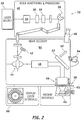
- FIG. 2 is a block diagram of an ophthalmic laser system 70 in accordance with another embodiment of the present invention.
- the ophthalmic laser system 70 illustrates the optical path of the pulsed laser beam in greater detail and includes, but is not necessarily limited to, a laser source 32 providing a pulsed laser beam (e.g. from the laser 14 shown in FIG. 1 ), a beam monitoring and processing module 40, a beam delivery module 50, and a user interface 60.
- the laser source 32, beam monitoring and processing module 40, and beam delivery module 50 collectively form a laser assembly.
- the pulsed laser beam is supplied to the beam monitoring and processing module 40 where operating characteristics of the pulsed laser beam are controlled, such as the pulse energy (e.g., varied by the energy control module 16 shown in FIG.
- the beam delivery module 50 scans the pulsed laser beam along a desired scan region.
- the ophthalmic laser system 70 can be coupled to an eye 64 via a patient interface 62, and the patient interface 62 may be coupled to the ophthalmic laser system 70 at a loading deck 58, for example.
- a display is provided by the user interface 60 for viewing the eye 64 undergoing laser treatment.
- the beam monitoring and processing module 40 includes, but is not necessarily limited to, an energy attenuator 34, one or more energy monitors 36, and an active beam positioning mirror 38.
- the pulsed laser beam is directed from the laser source 32 to the energy attenuator 34, then to the energy monitor 36, and then to the active beam positioning mirror 38.
- the active beam positioning mirror 38 directs the pulsed laser beam from the beam monitoring and processing module 40 to the beam delivery module 50.
- the pulse energy of the pulsed laser beam may be varied to desired values.
- the spatial separation of the focal points of the pulsed laser beam may be varied by the beam monitoring and processing module 40.
- the beam delivery module 50 scans the pulsed laser beam at the desired scan region (e.g., a sub-surface region of the eye 64, such as within the corneal epithelium and on or within Bowman's layer, the stroma, Descemet's membrane, the endothelium, and the like).
- the beam delivery module 50 includes, but is not necessarily limited to, a beam position monitor 42, an x-y scanner 44 (e.g., such as the scanner 20 shown in FIG. 1 ), a beam expander 46, one or more beam splitters 52, and a z-scanning objective 56.
- the beam delivery module 50 additionally includes an operating microscope 48 and a video camera 54 to enhance viewing of the eye 64.
- the pulsed laser beam is received from the beam monitoring and processing module 40 by the x-y scanner 44 and directed to the beam expander 46, and the beam expander 46 directs the pulsed laser beam to the z-scanning objective via the beam splitter(s) 52.
- the z-scanning objective 56 can vary the focal point depth of the pulsed laser beam.
- the z-scanning objective 56 can vary the focal point depth to the minimum focal point depth determined for the eye 64 or the desired region of the eye 64 and for the selected operating pulse energy and operating focal point separation.
- the configuration of the ophthalmic laser system 70 may vary as well as the organization of the various components and sub-components of the ophthalmic laser system 70.
- some sub-components of the beam delivery module 50 may be incorporated with the beam monitoring and processing module 40 and vice versa.
- the user interface 60 presents a variety of corneal implant options for selection by the user.
- the user interface 60 includes, but is not necessarily limited to, a display and an input device, such as a touch-screen, a mouse, a keyboard, a touch-pad, or the like.
- Multiple images representing different types of corneal tissue implants are presented on the display, and the user may select the appropriate corneal tissue implant for a particular ophthalmic procedure.
- the user may indicate a corneal tissue implant selection by touching the image on the touch-screen corresponding with the appropriate corneal implant.
- corneal tissue implant types include, but are not necessarily limited to, a variety of discs with varying radii of curvatures associated with the anterior and/or posterior surfaces of the disc and/or with varying cross-sectional shapes, single or multi-perforated discs, multi-component implants, crescents, rings, lenses, and the like. Additional corneal tissue implant types may be derived from variants of these examples based on pre-determined sizes or dimensions.
- Each corneal tissue implant type is associated with one or more parameters which may be selected or modified by the user (e.g., sub-surface depth, shape, size, diameter, thickness, radii, edge type, surface contour, cross-sectional profile, perimeter profile, and the like).
- the dimensions of a corneal tissue implant type may be used to pre-program incision parameters (e.g., length, depth, volume, shape, and the like) to be produced by the incision procedure.
- the system 10, 70 can form a corresponding incision or pocket in the recipient cornea.
- Pre-programmed e.g., stored in the memory database accessible by the controller 22
- updateable incisions e.g., via the input port or memory read device of the user interface 28, 60
- a desired corneal tissue implant e.g., lens shaped type, such as biconvex, plano-convex, multifocal, aspheric, and the like, polygonal shaped type, and the like
- the appropriate incision or cavity e.g., a pocket
- stromal bed e.g., a pocket
- this data is provided to the controller 22 ( FIG. 1 ).
- the controller 22 selects a pre-determined procedure (e.g., incision types and sequence), corresponding with the corneal tissue implant parameters, from among a stored database of pre-determined procedures and can modify the procedure to correspond with the corneal tissue implant parameters.
- a pre-determined procedure e.g., incision types and sequence
- the system 10, 70 includes a memory having a database.
- the memory stores an operating system module and a graphical user interface (GUI) module.
- the operating system module may include executable instructions for handling various system services, such as file services or for performing hardware dependant tasks.
- the GUI module may rely upon standard techniques to produce graphical components on the user interface 60, e.g., windows, icons, buttons, menus, drop-down menus, and the like, examples of which are discussed below.
- the GUI module may include executable instructions to receive input from a pointer device (e.g., a mouse, a keyboard, a touch-pad, and the like) or touch-screen and display a cursor on the user interface 60.
- the GUI module includes executable instructions for selecting items in the GUI and image processing of the eye and implant position within the eye.
- the executable modules stored in memory are exemplary. It should be appreciated that the functions of the modules may be combined or divided into additional modules.
- the database includes a catalog of corneal tissue implant types and a catalog of pre-determined incision procedures. Although described with catalogs, the database may be implemented with one or more look-up tables or other data management configurations. Each of the incision procedures corresponds to a different corneal tissue implant type, and the catalogs may be periodically updated.
- the incision procedures are designated for association with the corresponding corneal tissue implant type, although a particular incision procedure may be applicable to more than one of the corneal tissue implant types.
- Some examples of corneal implant types include, but are not necessarily limited to, a variety of discs with varying radii of curvatures associated with the anterior and/or posterior surfaces of the disc and/or with varying cross-sectional shapes, single or multi-perforated discs, multi-component implants, crescents, rings, lenses, and the like. Additional corneal tissue implant types may be derived from variants of these examples based on pre-determined sizes or dimensions. Combinations of corneal tissue implant types and incisions to provide refractive corrections may also be cataloged.
- the incision parameters are presented on the user interface 60 and may be modified by the user.
- drop-down menus, input blocks, incremental blocks, and the like may be used to set or modify one or more incision parameters (e.g., default incision parameter settings), the number and/or type of incisions, and the like associated with the particular incision procedure.
- Wavefront analysis, OCT maps, pupil dynamics (e.g., to assist with centration, incision selection, and/or implant selection), centration, iris registration, and the like may also be used to determine incision parameters.
- the system 10, 70 can determine a proper positioning or placement of the corneal tissue implant.
- One technique implemented by the system 10, 70 includes a shape registration, a feature registration, and iterative positioning using a closed loop feedback method.
- the shape registration refers to matching contours of the corneal tissue implant with the recipient bed (or pocket) to register the implant with an optical axis of the recipient's eye and enhance positional stability of the implant.
- some portions or all of the contour and/or one or more external structural features of the implant are formed in the recipient bed such that the implant is aligned with the optical axis following insertion.
- Some portions of the contour or one or more of the external structural features may be more relevant to alignment with the optical axis and thus may be emphasized for formation in the recipient bed.
- the laser assembly (e.g., using a femtosecond laser) is programmed to create a recipient bed with stability and registration enhanced contour (e.g., positional spikes).
- the laser assembly can modify the implant to a substantially equivalent contour as the recipient bed and create a corneal flap or incision.
- the incision or flap is opened, the corneal implant is inserted so that the contours align, and the incision or flap is repositioned.
- Feature registration refers to using a marker or other distinct feature of the implant for alignment with a feature of the eye (e.g., a pupil center position, an iris center position, an iris structure, and the like).
- the corneal inlay can be formed with at least one distinct mark of known location on or within the inlay.
- An image of the recipient's eye is obtained (e.g., as displayed via the user interface 28, 60), and the intended location of the marker(s) on the corneal implant is determined (e.g., via treatment software in the system 10, 70).
- image processing by the system 10, 70 determines the current location of the marker(s) and calculates an error signal for guiding the placement of the implant.
- the error signal can be represented on the user interface 28, 60 by overlays on the displayed image, although a variety of other techniques can be used (e.g., relative x-y coordinate values based on the optical axis, proximity indicators, and the like).
- the corneal tissue implant is preferably selected to achieve a desired post-operative anterior corneal surface corresponding with a desired optical performance of the eye.
- non-optimal placement of the corneal implant can generate an error signal, for example, based on corneal topography, wavefront measurement, pachymetry, and the like.
- the position of the implant is iteratively modified until the resulting error signal is substantially zero or within a pre-determined acceptable margin of error.
- FIG. 3 is a cross-sectional view of a donor cornea 72 illustrating the formation of some corneal tissue inlays 78, 84, 86, 88, 90 in accordance with one embodiment.
- the donor cornea 72 has an epithelium 74 and an endothelium 76, among other structures (not shown).
- multiple corneal tissue inlays 78, 84, 86, 88, 90 are incised (e.g., using the system 10, 70) from the donor cornea 72.
- the sequence or order of the inlays 78, 84, 86, 88, 90 as well as the type may be selected to maximize the number of inlays that may be incised and extracted from the donor cornea 72.
- a lens shaped lenticule 78, a planar shaped lenticule 88, a meniscus shaped lenticule 90, a larger ring shaped lenticule 84, and a smaller ring shaped lenticule 86 are incised from the donor cornea 72. Additional incisions 80 and 82 may be made in the donor cornea 72 to extract the various corneal tissue inlays 78, 88, and 90, and these incisions 80, 82 can form a cap or flap that may be lifted to reveal each respective inlay 78, 88, and 90.
- FIG. 4 is a cross-sectional view of a recipient cornea 92 illustrating a pocket formation in accordance with one embodiment.
- the recipient cornea 92 has an epithelium 94 and an endothelium 96, among other structures (not shown).
- a lenticule (not shown) is incised and removed from the recipient cornea 92 to form a pocket 98, and an access 100 is incised to the pocket 98.
- the lenticule dimensions are preferably based on the refractive correction requirements for the recipient eye. A simple sub-surface incision may be made in place of incising the lenticule.
- the access 100 provides a conduit from the anterior surface of the cornea 92 to the pocket 98 for inserting the corneal tissue inlay.
- FIG. 5 is a top view of a corneal tissue inlay 106 and a portion of an inserter 102 in accordance with one embodiment.
- FIG. 6 is a top view of the corneal tissue inlay 106 and the inserter 102 shown in FIG. 5 illustrating an insertion mode in accordance with one embodiment.
- the inserter 102 preferably has a non-stick surface and includes a handle 104 for user manipulation of the inserter 102.
- the inserter 102 has shape memory and is biased in a rolled configuration, such as shown in FIG. 6 .
- a conventional intraocular lens inserter may be used with the corneal tissue inlay 106.
- the corneal tissue inlay 106 is placed on the inserter 102.
- the corneal tissue inlay 106 is rolled-up with a portion of the inserter 102 (e.g., a head) to have a narrow or slim configuration, which is useful for minimizing the dimensions of the access 100 ( FIG. 4 ).
- a low-friction or non-stick coating can also be applied to one or more surfaces of the inlay 106.
- the inserter 102 may be manipulated through the access 100 to locate the corneal tissue inlay in the pocket 98 ( FIG. 4 ), and the corneal tissue inlay 106 can be un-rolled within the pocket 98. The inserter 102 can then be extracted from the pocket 98.
- a probe, push-rod, or other simple device may be used together with the inserter 102 to assist in depositing the corneal tissue inlay 106 within the pocket 98.
- a flap is incised in the recipient cornea and lifted to reveal a corneal bed, the corneal tissue inlay 106 is deposited onto the corneal bed, and the flap is placed over the corneal tissue inlay 106.
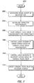
- FIG. 7 is a flow diagram of a method 200 for modifying a refractive profile of an eye.
- Visual acuity issues are determined for a recipient, as indicated at 202. For example, myopia, presbyopia, hyperopia, higher order aberrations, and the like, are determined for the recipient.
- Examples of devices to determine visual acuity issues include, but are not necessarily limited to, measurement devices such as Shack-Hartmann aberrometer, topographer, OCT, pachymeter, interferometry based devices, and other conventional visual acuity diagnostic devices. Additionally, pupilometry, iris registration, and/or residual accommodation may be used to determine visual acuity issues.
- Corrective requirements are determined for the recipient, as indicated at 204.
- corrections include, by way of example and not of limitation, refractive power change, multifocality, increase/decrease spherical aberration, higher order aberrations, and the like.
- modeling and/or designing a correction can be made based on corneal thickness, shape changes, or both.
- the recipient cornea can be made thicker and more steeply curved to improve hyperopia.
- a central biconvex shaped corneal tissue inlay or plano-convex shaped corneal tissue inlay can increase the steepness of the cornea, whereas a ring-shaped corneal tissue inlay can flatten the cornea.
- a rigid, multifocal corneal tissue inlay can effect a multifocal cornea.
- the recipient cornea can be shaped to be more aspheric to enhance the depth of focus and/or reduce spherical aberration to improve visual acuity.
- Corneal tissue inlay requirements for achieving the corrective requirements are planned, as indicated at 206.
- a shape e.g., biconvex, plano-convex, multifocal, aspheric, and the like
- physical dimensions e.g., diameter, thickness, curvature, radii, profile, edge configuration, and the like
- incision parameters of the recipient cornea may be planned.
- an intrastromal pocket size and shape and an access incision may be determined for receiving the corneal tissue inlay.
- Pupil dynamics may also be accounted for in determining the corneal tissue inlay requirements.
- Incisions in a donor cornea are controlled based on the corneal tissue inlay requirements, as indicated at 208.
- an ophthalmic surgical laser e.g., a femtosecond laser
- the incisions may be pre-determined to produce a pocket that matches the corneal tissue inlay.
- the incisions can be differently sized to create a different resulting recipient cornea shape (e.g., post implant or insertion of the corneal tissue inlay).
- the access incision can be limited to control egress of the corneal tissue inlay following insertion. Textured or shaped incisions may also be used to increase post-procedure healing and biomechanical strength of the recipient cornea.
- An axis associated with the access incision can be superiorly located to minimize gravity effects on the recipient cornea and/or to limit or correct astigmatism.
- Incisions in a recipient cornea are controlled based on the incision parameters, as indicated at 210.
- the ophthalmic surgical laser is controlled to incise the recipient cornea.
- the corneal tissue inlay is inserted into the recipient cornea, as indicated at 212, such as by manual manipulation with a blunt probe, forceps, or the like.
- the lenticule can be sculpted or otherwise modified to impart one or more of the corneal tissue inlay requirements.
- a femtosecond laser may be used to photoalter the anterior surface, the posterior surface, or a sub-surface layer of the lenticule.
- the femtosecond laser may photoalter the edge of the lenticule to enhance the biomechanical stability of the corneal tissue inlay post-insertion.
- the femtosecond laser may be used to produce a zig-zag edge.
- An excimer laser may also be used to photoalter one or both of the anterior and posterior surface of the lenticule (e.g., PRK). Fiducials, iris registration, pupil centration, or other orientation techniques may be used with the corneal tissue inlay for proper orientation of the corneal tissue inlay in the recipient cornea.
- systems and methods of preparing a flap of a material with a pulsed laser beam are disclosed that improve the biomechanical integrity of material with the flap reintegrated therewith.
- these systems and methods pro-actively enhance the healing of corneal flaps or corneal transplants.
Landscapes
- Health & Medical Sciences (AREA)
- Ophthalmology & Optometry (AREA)
- Animal Behavior & Ethology (AREA)
- General Health & Medical Sciences (AREA)
- Veterinary Medicine (AREA)
- Engineering & Computer Science (AREA)
- Biomedical Technology (AREA)
- Heart & Thoracic Surgery (AREA)
- Vascular Medicine (AREA)
- Life Sciences & Earth Sciences (AREA)
- Public Health (AREA)
- Oral & Maxillofacial Surgery (AREA)
- Cardiology (AREA)
- Transplantation (AREA)
- Physics & Mathematics (AREA)
- Optics & Photonics (AREA)
- Nuclear Medicine, Radiotherapy & Molecular Imaging (AREA)
- Surgery (AREA)
- Prostheses (AREA)
- Laser Surgery Devices (AREA)
Claims (11)
- Système (10) de modification d'un profil de réfraction associé à un oeil ayant une cornée receveuse, le système comprenant :une interface utilisateur (28) opérationnelle pour afficher une image de l'oeil ;un ensemble laser (14, 16, 20, 26) opérationnel pour fournir en sortie un faisceau laser à impulsions ; etun régulateur (22) couplé à l'ensemble laser et à l'interface utilisateur, le régulateur étant opérationnel pour diriger l'ensemble laser pour :inciser une incrustation de tissu cornéen à partir d'une cornée donneuse, l'incrustation de tissu cornéen ayant un profil de réfraction adapté pour corriger le profil de réfraction de l'oeil et ayant un contour ;former un lit receveur dans la cornée receveuse, le lit receveur ayant un contour concordant avec le contour de l'incrustation de tissu cornéen ; etdéterminer une position de l'incrustation de tissu cornéen ;caractérisé en ce quele régulateur est opérationnel pour diriger l'ensemble laser pour :déterminer un signal d'erreur pour l'incrustation de tissu cornéen d'après la position de l'incrustation de tissu cornéen pour aligner le profil de réfraction de l'incrustation de tissu cornéen avec le profil de réfraction de l'oeil, le signal d'erreur étant indiqué sur l'image de l'oeil.
- Système (10) selon la revendication 1, dans lequel le régulateur est opérationnel pour diriger l'ensemble laser pour déterminer un changement de position pour l'incrustation de tissu cornéen d'après la position de l'incrustation de tissu cornéen pour aligner le profil de réfraction de l'incrustation de tissu cornéen avec le profil de réfraction de l'oeil.
- Système selon la revendication 1 ou 2, dans lequel le régulateur est en outre configuré pour diriger l'ensemble laser pour :inciser une portion de la cornée donneuse, la portion ayant une surface antérieure et une surface postérieure ; etsculpter au moins l'une de la surface antérieure et de la surface postérieure en conformité avec le profil de réfraction de l'incrustation de tissu cornéen.
- Système selon l'une quelconque des revendications 1 à 3, dans lequel le régulateur est en outre configuré pour diriger l'ensemble laser pour inciser un ou plusieurs lenticules à partir de la cornée donneuse, les un ou plusieurs lenticules ayant le profil de réfraction de l'incrustation de tissu cornéen et choisis dans un groupe consistant en un lenticule biconvexe, un lenticule plano-convexe, un lenticule convexe-concave et un lenticule en forme de bague.
- Système selon l'une quelconque des revendications 1 à 4, dans lequel le régulateur est en outre configuré pour diriger l'ensemble laser pour inciser une portion de subsurface ayant une section droite polygonale à partir de la cornée donneuse, la portion de subsurface ayant le profil de réfraction de l'incrustation de tissu cornéen.
- Système selon l'une quelconque des revendications 1 à 5, dans lequel le régulateur est en outre configuré pour diriger l'ensemble laser pour inciser une portion de subsurface ayant un périmètre à partir de la cornée donneuse, la portion de subsurface ayant le profil de réfraction de l'incrustation de tissu cornéen, le périmètre étant choisi dans le groupe consistant en un périmètre rond, un périmètre ovale et un périmètre polygonal.
- Système selon l'une quelconque des revendications 1 à 6, dans lequel le régulateur est en outre configuré pour diriger l'ensemble laser pour inciser un bord de la portion de subsurface, le bord étant configuré pour stabiliser biomécaniquement une position de l'incrustation de tissu cornéen dans le lit receveur.
- Système selon l'une quelconque des revendications 1 à 7, dans lequel l'oeil a un axe optique, et dans lequel le régulateur est en outre configuré pour aligner l'incrustation de tissu cornéen avec l'axe optique et stabiliser l'incrustation de tissu cornéen dans le lit receveur en faisant coïncider l'incrustation de tissu cornéen avec le lit receveur.
- Système selon l'une quelconque des revendications 1 à 8, dans lequel l'incrustation de tissu cornéen a un marqueur d'orientation, et dans lequel le régulateur est en outre configuré pour déterminer un alignement du marqueur d'orientation avec une ou plusieurs parmi une position de centre de la pupille, une position de centre de l'iris et une structure de l'iris.
- Système selon l'une quelconque des revendications 1 à 9, dans lequel l'incrustation de tissu cornéen a un marqueur d'orientation, et dans lequel le régulateur est en outre configuré pour :faire concorder un contour de l'incrustation de tissu cornéen avec un contour du lit receveur ; etaligner le marqueur d'orientation avec une particularité de l'oeil.
- Système selon l'une quelconque des revendications 1 à 10, dans lequel le régulateur est en outre configuré pour aligner le marqueur d'orientation avec une ou plusieurs parmi une position de centre de la pupille, une position de centre de l'iris et une structure de l'iris.
Priority Applications (1)
| Application Number | Priority Date | Filing Date | Title |
|---|---|---|---|
| EP15157540.4A EP2926769A1 (fr) | 2008-06-27 | 2009-06-29 | Incrustation intracornéenne, système et procédé |
Applications Claiming Priority (2)
| Application Number | Priority Date | Filing Date | Title |
|---|---|---|---|
| US7659208P | 2008-06-27 | 2008-06-27 | |
| PCT/US2009/049117 WO2009158723A2 (fr) | 2008-06-27 | 2009-06-29 | Incrustation intracornéenne, et système et procédé correspondants |
Related Child Applications (2)
| Application Number | Title | Priority Date | Filing Date |
|---|---|---|---|
| EP15157540.4A Division-Into EP2926769A1 (fr) | 2008-06-27 | 2009-06-29 | Incrustation intracornéenne, système et procédé |
| EP15157540.4A Division EP2926769A1 (fr) | 2008-06-27 | 2009-06-29 | Incrustation intracornéenne, système et procédé |
Publications (2)
| Publication Number | Publication Date |
|---|---|
| EP2337523A2 EP2337523A2 (fr) | 2011-06-29 |
| EP2337523B1 true EP2337523B1 (fr) | 2017-08-16 |
Family
ID=41445393
Family Applications (2)
| Application Number | Title | Priority Date | Filing Date |
|---|---|---|---|
| EP15157540.4A Withdrawn EP2926769A1 (fr) | 2008-06-27 | 2009-06-29 | Incrustation intracornéenne, système et procédé |
| EP09771254.1A Not-in-force EP2337523B1 (fr) | 2008-06-27 | 2009-06-29 | Système de modification d'un profil de réfraction à l'aide d'une incrustation de cornée |
Family Applications Before (1)
| Application Number | Title | Priority Date | Filing Date |
|---|---|---|---|
| EP15157540.4A Withdrawn EP2926769A1 (fr) | 2008-06-27 | 2009-06-29 | Incrustation intracornéenne, système et procédé |
Country Status (3)
| Country | Link |
|---|---|
| US (1) | US8246609B2 (fr) |
| EP (2) | EP2926769A1 (fr) |
| WO (1) | WO2009158723A2 (fr) |
Families Citing this family (46)
| Publication number | Priority date | Publication date | Assignee | Title |
|---|---|---|---|---|
| US8668735B2 (en) | 2000-09-12 | 2014-03-11 | Revision Optics, Inc. | Corneal implant storage and delivery devices |
| US20110098790A1 (en) * | 2009-10-26 | 2011-04-28 | Albert Daxer | Methods for treating corneal disease |
| US10835371B2 (en) | 2004-04-30 | 2020-11-17 | Rvo 2.0, Inc. | Small diameter corneal inlay methods |
| US10555805B2 (en) | 2006-02-24 | 2020-02-11 | Rvo 2.0, Inc. | Anterior corneal shapes and methods of providing the shapes |
| MX2008014751A (es) | 2006-05-23 | 2009-02-10 | Albert Daxer | Implante corneal y metodo para la correccion de defectos de la vision del ojo humano. |
| US9549848B2 (en) | 2007-03-28 | 2017-01-24 | Revision Optics, Inc. | Corneal implant inserters and methods of use |
| US9271828B2 (en) | 2007-03-28 | 2016-03-01 | Revision Optics, Inc. | Corneal implant retaining devices and methods of use |
| US8764737B2 (en) | 2007-09-06 | 2014-07-01 | Alcon Lensx, Inc. | Precise targeting of surgical photodisruption |
| US20110224659A1 (en) * | 2007-12-17 | 2011-09-15 | Luis Antonio Ruiz | Intrastromal Hyperplanes for Vision Correction |
| US9539143B2 (en) | 2008-04-04 | 2017-01-10 | Revision Optics, Inc. | Methods of correcting vision |
| US20110028948A1 (en) * | 2009-07-29 | 2011-02-03 | Lensx Lasers, Inc. | Optical System for Ophthalmic Surgical Laser |
| US9504608B2 (en) * | 2009-07-29 | 2016-11-29 | Alcon Lensx, Inc. | Optical system with movable lens for ophthalmic surgical laser |
| CA2769432A1 (fr) * | 2009-08-03 | 2011-02-10 | Wavelight Gmbh | Dispositif de chirurgie ophtalmologique par laser |
| US8506559B2 (en) * | 2009-11-16 | 2013-08-13 | Alcon Lensx, Inc. | Variable stage optical system for ophthalmic surgical laser |
| US20120022408A1 (en) * | 2010-06-18 | 2012-01-26 | Vantage Surgical Systems, Inc. | Surgical Procedures Using Visual Images Overlaid with Visual Representations of Selected Three-Dimensional Data |
| WO2012035403A1 (fr) * | 2010-09-13 | 2012-03-22 | Singapore Health Services Pte Ltd | Procédé de réalisation d'une procédure de réfraction réversible |
| US9155659B2 (en) | 2010-10-19 | 2015-10-13 | Wake Forest University Health Sciences | One-card presbyopia treatment laser systems and related methods |
| CN103415268B (zh) * | 2011-02-15 | 2016-04-06 | 视乐有限公司 | 辅助在人眼中移植角膜假体的装置 |
| DE102011106289A1 (de) * | 2011-07-01 | 2013-01-03 | Carl Zeiss Meditec Ag | Hornhautimplantat |
| WO2013059813A1 (fr) | 2011-10-21 | 2013-04-25 | Revision Optics, Inc. | Dispositifs de stockage et de pose d'implant cornéen |
| US9033497B2 (en) | 2011-12-29 | 2015-05-19 | Elwha Llc | Optical device with interchangeable corrective elements |
| US20130169928A1 (en) * | 2011-12-29 | 2013-07-04 | Elwha LLC, a limited liability company of the State of Delaware | Fabrication technique for replaceable optical corrective elements |
| US9046683B2 (en) | 2011-12-29 | 2015-06-02 | Elwha Llc | Adjustable optics for ongoing viewing correction |
| CN106726125B (zh) * | 2012-01-18 | 2019-07-05 | 视乐有限公司 | 根据光密度对激光能量进行调节的外科手术设备 |
| US8852177B2 (en) | 2012-03-09 | 2014-10-07 | Alcon Lensx, Inc. | Spatio-temporal beam modulator for surgical laser systems |
| US10182943B2 (en) | 2012-03-09 | 2019-01-22 | Alcon Lensx, Inc. | Adjustable pupil system for surgical laser systems |
| TWI588560B (zh) | 2012-04-05 | 2017-06-21 | 布萊恩荷登視覺協會 | 用於屈光不正之鏡片、裝置、方法及系統 |
| US20130310728A1 (en) * | 2012-05-16 | 2013-11-21 | Theo Seiler | Device for dissecting an eye for the introduction of photosensitizer and method of refractive surgery |
| DE102012016379A1 (de) * | 2012-08-16 | 2014-02-20 | Carl Zeiss Meditec Ag | Verfahren zur Vermessung eines Auges |
| DE102012018421A1 (de) * | 2012-09-14 | 2014-03-20 | Carl Zeiss Meditec Ag | Augenchirurgische Refraktionskorrektur |
| US9201250B2 (en) | 2012-10-17 | 2015-12-01 | Brien Holden Vision Institute | Lenses, devices, methods and systems for refractive error |
| KR102199677B1 (ko) | 2012-10-17 | 2021-01-08 | 브리엔 홀덴 비전 인스티튜트 리미티드 | 굴절 오류를 위한 렌즈들, 디바이스들, 방법들 및 시스템들 |
| US10092393B2 (en) * | 2013-03-14 | 2018-10-09 | Allotex, Inc. | Corneal implant systems and methods |
| US9844465B2 (en) * | 2013-07-29 | 2017-12-19 | Lensar, Inc. | Second pass femtosecond laser for incomplete laser full or partial thickness corneal incisions |
| WO2015183941A1 (fr) * | 2014-05-27 | 2015-12-03 | Revision Optics, Inc. | Implants cornéens et procédés de fabrication |
| EP3226808A4 (fr) | 2014-12-01 | 2018-07-25 | Marwan Ghabra | Implants intra-cornéens et leurs procédés d'utilisation |
| WO2016144404A1 (fr) | 2015-03-12 | 2016-09-15 | Revision Optics, Inc. | Procédés de correction de la vision |
| US10449090B2 (en) | 2015-07-31 | 2019-10-22 | Allotex, Inc. | Corneal implant systems and methods |
| DE102016208012A1 (de) | 2016-05-10 | 2017-11-16 | Carl Zeiss Meditec Ag | Augenchirurgisches Verfahren |
| EP3245989A1 (fr) * | 2016-05-17 | 2017-11-22 | Ziemer Ophthalmic Systems AG | Dispositif de traitement ophtalmologique |
| AU2017280237B2 (en) | 2016-06-22 | 2022-07-07 | Amo Development, Llc | Improved methods for lenticular laser incision |
| US11083565B2 (en) | 2017-06-05 | 2021-08-10 | Corneagen Inc. | Systems and methods for corneal transplants |
| US11529259B2 (en) | 2017-10-26 | 2022-12-20 | Amo Development, Llc | Femtosecond laser system and methods for photorefractive keratectomy |
| US11559390B2 (en) * | 2017-10-27 | 2023-01-24 | Allotex, Inc. | Corneal implant systems and methods |
| WO2019118790A1 (fr) | 2017-12-13 | 2019-06-20 | Allotex, Inc. | Systèmes d'implant cornéen et procédés |
| DE102019118315A1 (de) * | 2019-07-05 | 2021-01-07 | Schwind Eye-Tech-Solutions Gmbh | Verfahren zur Steuerung eines augenchirurgischen Lasers und Behandlungsvorrichtung |
Family Cites Families (24)
| Publication number | Priority date | Publication date | Assignee | Title |
|---|---|---|---|---|
| US4646720A (en) * | 1985-03-12 | 1987-03-03 | Peyman Gholam A | Optical assembly permanently attached to the cornea |
| US4764930A (en) | 1988-01-27 | 1988-08-16 | Intelligent Surgical Lasers | Multiwavelength laser source |
| US5312428A (en) | 1991-10-10 | 1994-05-17 | Lieberman David M | Corneal punch and method of use |
| US5647865A (en) | 1991-11-01 | 1997-07-15 | Swinger; Casimir A. | Corneal surgery using laser, donor corneal tissue and synthetic material |
| US5984916A (en) * | 1993-04-20 | 1999-11-16 | Lai; Shui T. | Ophthalmic surgical laser and method |
| CN2132492Y (zh) * | 1992-07-15 | 1993-05-12 | 杨朝忠 | 一种角膜刻切器 |
| WO1994009849A1 (fr) * | 1992-10-26 | 1994-05-11 | Swinger Casimir A | Methode de chirurgie ophtalmique |
| US5549632A (en) | 1992-10-26 | 1996-08-27 | Novatec Laser Systems, Inc. | Method and apparatus for ophthalmic surgery |
| US5993438A (en) | 1993-11-12 | 1999-11-30 | Escalon Medical Corporation | Intrastromal photorefractive keratectomy |
| US5656186A (en) | 1994-04-08 | 1997-08-12 | The Regents Of The University Of Michigan | Method for controlling configuration of laser induced breakdown and ablation |
| US20010018612A1 (en) * | 1997-08-07 | 2001-08-30 | Carson Daniel R. | Intracorneal lens |
| US6949093B1 (en) * | 2000-03-21 | 2005-09-27 | Minu, L.L.C. | Adjustable universal implant blank for modifying corneal curvature and methods of modifying corneal curvature therewith |
| CN100442006C (zh) * | 2002-05-30 | 2008-12-10 | 维思克斯公司 | 跟踪扭转的眼睛的方向和位置 |
| US20030223954A1 (en) * | 2002-05-31 | 2003-12-04 | Ruscio Dominic V. | Polymeric materials for use as photoablatable inlays |
| DE10237945A1 (de) | 2002-08-20 | 2004-03-11 | Quintis Gmbh | Laserbasierte Vorrichtung zur nichtmechanischen, dreidimensionalen Trepanation bei Hornhauttransplantationen |
| US7351241B2 (en) | 2003-06-02 | 2008-04-01 | Carl Zeiss Meditec Ag | Method and apparatus for precision working of material |
| US20080262610A1 (en) * | 2007-04-20 | 2008-10-23 | Alan Lang | Biomechanical design of intracorneal inlays |
| US20060020259A1 (en) * | 2004-07-20 | 2006-01-26 | Klaus Baumeister | System for performing a corneal transplantation |
| US7390089B2 (en) * | 2005-02-25 | 2008-06-24 | 20/10 Perfect Vision Optische Geraete Gmbh | Device and method for aligning an eye with a surgical laser |
| US9402714B2 (en) | 2006-03-06 | 2016-08-02 | Amo Development, Llc | Method of transplanting a cornea |
| US20080058841A1 (en) * | 2006-09-05 | 2008-03-06 | Kurtz Ronald M | System and method for marking corneal tissue in a transplant procedure |
| US20080082086A1 (en) * | 2006-09-05 | 2008-04-03 | Kurtz Ronald M | System and method for resecting corneal tissue |
| US20080114386A1 (en) | 2006-11-09 | 2008-05-15 | Bernardino Iliakis | Method of providing corneal tissue and method of determining the bioburden of laboratory providing same |
| DE102007019815A1 (de) * | 2007-04-26 | 2008-10-30 | Carl Zeiss Meditec Ag | Augenhornhaut-Transplantation |
-
2009
- 2009-06-29 WO PCT/US2009/049117 patent/WO2009158723A2/fr active Application Filing
- 2009-06-29 US US12/494,092 patent/US8246609B2/en not_active Expired - Fee Related
- 2009-06-29 EP EP15157540.4A patent/EP2926769A1/fr not_active Withdrawn
- 2009-06-29 EP EP09771254.1A patent/EP2337523B1/fr not_active Not-in-force
Non-Patent Citations (1)
| Title |
|---|
| None * |
Also Published As
| Publication number | Publication date |
|---|---|
| EP2337523A2 (fr) | 2011-06-29 |
| WO2009158723A3 (fr) | 2010-04-15 |
| WO2009158723A2 (fr) | 2009-12-30 |
| US8246609B2 (en) | 2012-08-21 |
| EP2926769A1 (fr) | 2015-10-07 |
| US20090326650A1 (en) | 2009-12-31 |
Similar Documents
| Publication | Publication Date | Title |
|---|---|---|
| EP2337523B1 (fr) | Système de modification d'un profil de réfraction à l'aide d'une incrustation de cornée | |
| EP2280677B1 (fr) | Système et interface d'implant de la cornée | |
| EP1996135B1 (fr) | Systèmes de correction réfractive intrastromale | |
| US9427357B2 (en) | Preformed lens systems and methods | |
| US20120035598A1 (en) | Device and method for producing control data for the surgical correction of defective eye vision | |
| EP2734161A1 (fr) | Compensation, mesure et réglage connexe de l'inclinaison selon des prescriptions de réfraction pendant des traitements chirurgicaux ou autres de l' il | |
| US12011394B2 (en) | Devices and methods for laser surgery of an eye, especially for keratoplasty | |
| US20230106593A1 (en) | Femtosecond laser system and methods for photorefractive keratectomy | |
| US20130131654A1 (en) | Systems and methods for fine-tuning refractive surgery | |
| EP2506812B1 (fr) | Systèmes et procédés pour une chirurgie réfractive à réglage précis | |
| US10783999B2 (en) | Basis data evaluation systems and methods | |
| US10028862B2 (en) | Compensation systems and methods for flap induced aberrations | |
| CN113692265B (en) | Device and method for laser surgery of the eye, in particular for cornea implantation |
Legal Events
| Date | Code | Title | Description |
|---|---|---|---|
| PUAI | Public reference made under article 153(3) epc to a published international application that has entered the european phase |
Free format text: ORIGINAL CODE: 0009012 |
|
| 17P | Request for examination filed |
Effective date: 20110125 |
|
| AK | Designated contracting states |
Kind code of ref document: A2 Designated state(s): AT BE BG CH CY CZ DE DK EE ES FI FR GB GR HR HU IE IS IT LI LT LU LV MC MK MT NL NO PL PT RO SE SI SK TR |
|
| AX | Request for extension of the european patent |
Extension state: AL BA RS |
|
| DAX | Request for extension of the european patent (deleted) | ||
| REG | Reference to a national code |
Ref country code: DE Ref legal event code: R079 Ref document number: 602009047786 Country of ref document: DE Free format text: PREVIOUS MAIN CLASS: A61F0002140000 Ipc: A61F0009008000 |
|
| RIC1 | Information provided on ipc code assigned before grant |
Ipc: A61F 9/008 20060101AFI20170125BHEP Ipc: A61F 2/14 20060101ALI20170125BHEP |
|
| GRAP | Despatch of communication of intention to grant a patent |
Free format text: ORIGINAL CODE: EPIDOSNIGR1 |
|
| INTG | Intention to grant announced |
Effective date: 20170307 |
|
| GRAS | Grant fee paid |
Free format text: ORIGINAL CODE: EPIDOSNIGR3 |
|
| GRAA | (expected) grant |
Free format text: ORIGINAL CODE: 0009210 |
|
| AK | Designated contracting states |
Kind code of ref document: B1 Designated state(s): AT BE BG CH CY CZ DE DK EE ES FI FR GB GR HR HU IE IS IT LI LT LU LV MC MK MT NL NO PL PT RO SE SI SK TR |
|
| REG | Reference to a national code |
Ref country code: GB Ref legal event code: FG4D |
|
| REG | Reference to a national code |
Ref country code: CH Ref legal event code: EP |
|
| REG | Reference to a national code |
Ref country code: IE Ref legal event code: FG4D |
|
| REG | Reference to a national code |
Ref country code: AT Ref legal event code: REF Ref document number: 918356 Country of ref document: AT Kind code of ref document: T Effective date: 20170915 |
|
| REG | Reference to a national code |
Ref country code: DE Ref legal event code: R096 Ref document number: 602009047786 Country of ref document: DE |
|
| REG | Reference to a national code |
Ref country code: NL Ref legal event code: MP Effective date: 20170816 |
|
| REG | Reference to a national code |
Ref country code: LT Ref legal event code: MG4D |
|
| REG | Reference to a national code |
Ref country code: AT Ref legal event code: MK05 Ref document number: 918356 Country of ref document: AT Kind code of ref document: T Effective date: 20170816 |
|
| PG25 | Lapsed in a contracting state [announced via postgrant information from national office to epo] |
Ref country code: AT Free format text: LAPSE BECAUSE OF FAILURE TO SUBMIT A TRANSLATION OF THE DESCRIPTION OR TO PAY THE FEE WITHIN THE PRESCRIBED TIME-LIMIT Effective date: 20170816 Ref country code: NO Free format text: LAPSE BECAUSE OF FAILURE TO SUBMIT A TRANSLATION OF THE DESCRIPTION OR TO PAY THE FEE WITHIN THE PRESCRIBED TIME-LIMIT Effective date: 20171116 Ref country code: SE Free format text: LAPSE BECAUSE OF FAILURE TO SUBMIT A TRANSLATION OF THE DESCRIPTION OR TO PAY THE FEE WITHIN THE PRESCRIBED TIME-LIMIT Effective date: 20170816 Ref country code: NL Free format text: LAPSE BECAUSE OF FAILURE TO SUBMIT A TRANSLATION OF THE DESCRIPTION OR TO PAY THE FEE WITHIN THE PRESCRIBED TIME-LIMIT Effective date: 20170816 Ref country code: LT Free format text: LAPSE BECAUSE OF FAILURE TO SUBMIT A TRANSLATION OF THE DESCRIPTION OR TO PAY THE FEE WITHIN THE PRESCRIBED TIME-LIMIT Effective date: 20170816 Ref country code: FI Free format text: LAPSE BECAUSE OF FAILURE TO SUBMIT A TRANSLATION OF THE DESCRIPTION OR TO PAY THE FEE WITHIN THE PRESCRIBED TIME-LIMIT Effective date: 20170816 |
|
| REG | Reference to a national code |
Ref country code: CH Ref legal event code: NV Representative=s name: E. BLUM AND CO. AG PATENT- UND MARKENANWAELTE , CH |
|
| PG25 | Lapsed in a contracting state [announced via postgrant information from national office to epo] |
Ref country code: LV Free format text: LAPSE BECAUSE OF FAILURE TO SUBMIT A TRANSLATION OF THE DESCRIPTION OR TO PAY THE FEE WITHIN THE PRESCRIBED TIME-LIMIT Effective date: 20170816 Ref country code: ES Free format text: LAPSE BECAUSE OF FAILURE TO SUBMIT A TRANSLATION OF THE DESCRIPTION OR TO PAY THE FEE WITHIN THE PRESCRIBED TIME-LIMIT Effective date: 20170816 Ref country code: IS Free format text: LAPSE BECAUSE OF FAILURE TO SUBMIT A TRANSLATION OF THE DESCRIPTION OR TO PAY THE FEE WITHIN THE PRESCRIBED TIME-LIMIT Effective date: 20171216 Ref country code: PL Free format text: LAPSE BECAUSE OF FAILURE TO SUBMIT A TRANSLATION OF THE DESCRIPTION OR TO PAY THE FEE WITHIN THE PRESCRIBED TIME-LIMIT Effective date: 20170816 Ref country code: BG Free format text: LAPSE BECAUSE OF FAILURE TO SUBMIT A TRANSLATION OF THE DESCRIPTION OR TO PAY THE FEE WITHIN THE PRESCRIBED TIME-LIMIT Effective date: 20171116 Ref country code: GR Free format text: LAPSE BECAUSE OF FAILURE TO SUBMIT A TRANSLATION OF THE DESCRIPTION OR TO PAY THE FEE WITHIN THE PRESCRIBED TIME-LIMIT Effective date: 20171117 |
|
| PG25 | Lapsed in a contracting state [announced via postgrant information from national office to epo] |
Ref country code: DK Free format text: LAPSE BECAUSE OF FAILURE TO SUBMIT A TRANSLATION OF THE DESCRIPTION OR TO PAY THE FEE WITHIN THE PRESCRIBED TIME-LIMIT Effective date: 20170816 Ref country code: CZ Free format text: LAPSE BECAUSE OF FAILURE TO SUBMIT A TRANSLATION OF THE DESCRIPTION OR TO PAY THE FEE WITHIN THE PRESCRIBED TIME-LIMIT Effective date: 20170816 Ref country code: RO Free format text: LAPSE BECAUSE OF FAILURE TO SUBMIT A TRANSLATION OF THE DESCRIPTION OR TO PAY THE FEE WITHIN THE PRESCRIBED TIME-LIMIT Effective date: 20170816 |
|
| REG | Reference to a national code |
Ref country code: FR Ref legal event code: PLFP Year of fee payment: 10 |
|
| REG | Reference to a national code |
Ref country code: DE Ref legal event code: R097 Ref document number: 602009047786 Country of ref document: DE |
|
| PG25 | Lapsed in a contracting state [announced via postgrant information from national office to epo] |
Ref country code: IT Free format text: LAPSE BECAUSE OF FAILURE TO SUBMIT A TRANSLATION OF THE DESCRIPTION OR TO PAY THE FEE WITHIN THE PRESCRIBED TIME-LIMIT Effective date: 20170816 Ref country code: EE Free format text: LAPSE BECAUSE OF FAILURE TO SUBMIT A TRANSLATION OF THE DESCRIPTION OR TO PAY THE FEE WITHIN THE PRESCRIBED TIME-LIMIT Effective date: 20170816 Ref country code: SK Free format text: LAPSE BECAUSE OF FAILURE TO SUBMIT A TRANSLATION OF THE DESCRIPTION OR TO PAY THE FEE WITHIN THE PRESCRIBED TIME-LIMIT Effective date: 20170816 |
|
| PLBE | No opposition filed within time limit |
Free format text: ORIGINAL CODE: 0009261 |
|
| STAA | Information on the status of an ep patent application or granted ep patent |
Free format text: STATUS: NO OPPOSITION FILED WITHIN TIME LIMIT |
|
| 26N | No opposition filed |
Effective date: 20180517 |
|
| PG25 | Lapsed in a contracting state [announced via postgrant information from national office to epo] |
Ref country code: SI Free format text: LAPSE BECAUSE OF FAILURE TO SUBMIT A TRANSLATION OF THE DESCRIPTION OR TO PAY THE FEE WITHIN THE PRESCRIBED TIME-LIMIT Effective date: 20170816 |
|
| REG | Reference to a national code |
Ref country code: BE Ref legal event code: MM Effective date: 20180630 |
|
| PG25 | Lapsed in a contracting state [announced via postgrant information from national office to epo] |
Ref country code: LU Free format text: LAPSE BECAUSE OF NON-PAYMENT OF DUE FEES Effective date: 20180629 Ref country code: MC Free format text: LAPSE BECAUSE OF FAILURE TO SUBMIT A TRANSLATION OF THE DESCRIPTION OR TO PAY THE FEE WITHIN THE PRESCRIBED TIME-LIMIT Effective date: 20170816 |
|
| REG | Reference to a national code |
Ref country code: IE Ref legal event code: MM4A |
|
| PG25 | Lapsed in a contracting state [announced via postgrant information from national office to epo] |
Ref country code: IE Free format text: LAPSE BECAUSE OF NON-PAYMENT OF DUE FEES Effective date: 20180629 |
|
| PG25 | Lapsed in a contracting state [announced via postgrant information from national office to epo] |
Ref country code: BE Free format text: LAPSE BECAUSE OF NON-PAYMENT OF DUE FEES Effective date: 20180630 |
|
| PGFP | Annual fee paid to national office [announced via postgrant information from national office to epo] |
Ref country code: CH Payment date: 20190614 Year of fee payment: 11 |
|
| PG25 | Lapsed in a contracting state [announced via postgrant information from national office to epo] |
Ref country code: MT Free format text: LAPSE BECAUSE OF NON-PAYMENT OF DUE FEES Effective date: 20180629 |
|
| PG25 | Lapsed in a contracting state [announced via postgrant information from national office to epo] |
Ref country code: TR Free format text: LAPSE BECAUSE OF FAILURE TO SUBMIT A TRANSLATION OF THE DESCRIPTION OR TO PAY THE FEE WITHIN THE PRESCRIBED TIME-LIMIT Effective date: 20170816 |
|
| PG25 | Lapsed in a contracting state [announced via postgrant information from national office to epo] |
Ref country code: PT Free format text: LAPSE BECAUSE OF FAILURE TO SUBMIT A TRANSLATION OF THE DESCRIPTION OR TO PAY THE FEE WITHIN THE PRESCRIBED TIME-LIMIT Effective date: 20170816 Ref country code: HU Free format text: LAPSE BECAUSE OF FAILURE TO SUBMIT A TRANSLATION OF THE DESCRIPTION OR TO PAY THE FEE WITHIN THE PRESCRIBED TIME-LIMIT; INVALID AB INITIO Effective date: 20090629 |
|
| PG25 | Lapsed in a contracting state [announced via postgrant information from national office to epo] |
Ref country code: HR Free format text: LAPSE BECAUSE OF FAILURE TO SUBMIT A TRANSLATION OF THE DESCRIPTION OR TO PAY THE FEE WITHIN THE PRESCRIBED TIME-LIMIT Effective date: 20170816 Ref country code: CY Free format text: LAPSE BECAUSE OF FAILURE TO SUBMIT A TRANSLATION OF THE DESCRIPTION OR TO PAY THE FEE WITHIN THE PRESCRIBED TIME-LIMIT Effective date: 20170816 Ref country code: MK Free format text: LAPSE BECAUSE OF NON-PAYMENT OF DUE FEES Effective date: 20170816 |
|
| REG | Reference to a national code |
Ref country code: CH Ref legal event code: PL |
|
| PG25 | Lapsed in a contracting state [announced via postgrant information from national office to epo] |
Ref country code: LI Free format text: LAPSE BECAUSE OF NON-PAYMENT OF DUE FEES Effective date: 20200630 Ref country code: CH Free format text: LAPSE BECAUSE OF NON-PAYMENT OF DUE FEES Effective date: 20200630 |
|
| PGFP | Annual fee paid to national office [announced via postgrant information from national office to epo] |
Ref country code: GB Payment date: 20220506 Year of fee payment: 14 Ref country code: FR Payment date: 20220510 Year of fee payment: 14 Ref country code: DE Payment date: 20220505 Year of fee payment: 14 |
|
| REG | Reference to a national code |
Ref country code: DE Ref legal event code: R119 Ref document number: 602009047786 Country of ref document: DE |
|
| GBPC | Gb: european patent ceased through non-payment of renewal fee |
Effective date: 20230629 |
|
| PG25 | Lapsed in a contracting state [announced via postgrant information from national office to epo] |
Ref country code: DE Free format text: LAPSE BECAUSE OF NON-PAYMENT OF DUE FEES Effective date: 20240103 Ref country code: GB Free format text: LAPSE BECAUSE OF NON-PAYMENT OF DUE FEES Effective date: 20230629 |
|
| PG25 | Lapsed in a contracting state [announced via postgrant information from national office to epo] |
Ref country code: FR Free format text: LAPSE BECAUSE OF NON-PAYMENT OF DUE FEES Effective date: 20230630 |