EP2337037A2 - Verfahren zur Herstellung eines gegossenen Magnetes - Google Patents
Verfahren zur Herstellung eines gegossenen Magnetes Download PDFInfo
- Publication number
- EP2337037A2 EP2337037A2 EP10194483A EP10194483A EP2337037A2 EP 2337037 A2 EP2337037 A2 EP 2337037A2 EP 10194483 A EP10194483 A EP 10194483A EP 10194483 A EP10194483 A EP 10194483A EP 2337037 A2 EP2337037 A2 EP 2337037A2
- Authority
- EP
- European Patent Office
- Prior art keywords
- face
- cavity
- magnetic flux
- magnetic
- body section
- Prior art date
- Legal status (The legal status is an assumption and is not a legal conclusion. Google has not performed a legal analysis and makes no representation as to the accuracy of the status listed.)
- Granted
Links
- 238000004519 manufacturing process Methods 0.000 title claims description 10
- 230000005291 magnetic effect Effects 0.000 claims abstract description 114
- 230000004907 flux Effects 0.000 claims abstract description 68
- 238000000465 moulding Methods 0.000 claims abstract description 41
- 239000000203 mixture Substances 0.000 claims abstract description 22
- 238000000034 method Methods 0.000 claims abstract description 21
- 239000011230 binding agent Substances 0.000 claims abstract description 14
- 239000004033 plastic Substances 0.000 claims abstract description 12
- 229920003023 plastic Polymers 0.000 claims abstract description 12
- 239000000945 filler Substances 0.000 claims abstract description 9
- KPLQYGBQNPPQGA-UHFFFAOYSA-N cobalt samarium Chemical compound [Co].[Sm] KPLQYGBQNPPQGA-UHFFFAOYSA-N 0.000 claims abstract description 5
- 229910000938 samarium–cobalt magnet Inorganic materials 0.000 claims abstract description 5
- 229910000859 α-Fe Inorganic materials 0.000 claims abstract description 5
- 239000007787 solid Substances 0.000 claims abstract description 4
- 230000005415 magnetization Effects 0.000 claims description 14
- 239000000463 material Substances 0.000 claims description 8
- 230000000295 complement effect Effects 0.000 claims description 6
- QJVKUMXDEUEQLH-UHFFFAOYSA-N [B].[Fe].[Nd] Chemical compound [B].[Fe].[Nd] QJVKUMXDEUEQLH-UHFFFAOYSA-N 0.000 claims description 3
- 229910001172 neodymium magnet Inorganic materials 0.000 claims description 3
- 239000002245 particle Substances 0.000 claims description 3
- 238000003466 welding Methods 0.000 claims description 3
- 230000005465 channeling Effects 0.000 claims description 2
- 239000012762 magnetic filler Substances 0.000 abstract 1
- 238000002347 injection Methods 0.000 description 6
- 239000007924 injection Substances 0.000 description 6
- 239000000696 magnetic material Substances 0.000 description 6
- 238000013519 translation Methods 0.000 description 5
- 230000008859 change Effects 0.000 description 4
- 230000002093 peripheral effect Effects 0.000 description 4
- 230000008569 process Effects 0.000 description 4
- 238000010586 diagram Methods 0.000 description 3
- 238000000605 extraction Methods 0.000 description 3
- 230000006698 induction Effects 0.000 description 3
- 239000013598 vector Substances 0.000 description 3
- CWYNVVGOOAEACU-UHFFFAOYSA-N Fe2+ Chemical compound [Fe+2] CWYNVVGOOAEACU-UHFFFAOYSA-N 0.000 description 2
- 230000000670 limiting effect Effects 0.000 description 2
- 239000012528 membrane Substances 0.000 description 2
- 239000000725 suspension Substances 0.000 description 2
- 229920001169 thermoplastic Polymers 0.000 description 2
- 230000008901 benefit Effects 0.000 description 1
- 239000012530 fluid Substances 0.000 description 1
- 238000010438 heat treatment Methods 0.000 description 1
- 239000008240 homogeneous mixture Substances 0.000 description 1
- 238000005304 joining Methods 0.000 description 1
- 230000009021 linear effect Effects 0.000 description 1
- 229920000642 polymer Polymers 0.000 description 1
- 239000000843 powder Substances 0.000 description 1
- 230000000284 resting effect Effects 0.000 description 1
- 238000007493 shaping process Methods 0.000 description 1
- 238000007514 turning Methods 0.000 description 1
Images

Classifications
-
- H—ELECTRICITY
- H01—ELECTRIC ELEMENTS
- H01F—MAGNETS; INDUCTANCES; TRANSFORMERS; SELECTION OF MATERIALS FOR THEIR MAGNETIC PROPERTIES
- H01F41/00—Apparatus or processes specially adapted for manufacturing or assembling magnets, inductances or transformers; Apparatus or processes specially adapted for manufacturing materials characterised by their magnetic properties
- H01F41/02—Apparatus or processes specially adapted for manufacturing or assembling magnets, inductances or transformers; Apparatus or processes specially adapted for manufacturing materials characterised by their magnetic properties for manufacturing cores, coils, or magnets
- H01F41/0253—Apparatus or processes specially adapted for manufacturing or assembling magnets, inductances or transformers; Apparatus or processes specially adapted for manufacturing materials characterised by their magnetic properties for manufacturing cores, coils, or magnets for manufacturing permanent magnets
- H01F41/0273—Imparting anisotropy
- H01F41/028—Radial anisotropy
-
- H—ELECTRICITY
- H01—ELECTRIC ELEMENTS
- H01F—MAGNETS; INDUCTANCES; TRANSFORMERS; SELECTION OF MATERIALS FOR THEIR MAGNETIC PROPERTIES
- H01F7/00—Magnets
- H01F7/02—Permanent magnets [PM]
- H01F7/0273—Magnetic circuits with PM for magnetic field generation
- H01F7/0289—Transducers, loudspeakers, moving coil arrangements
Definitions
- the present invention relates to a method of manufacturing a molded magnet.
- the document EP 2,114,086 relates to a loudspeaker motor, comprising such a magnet.
- these magnets are made in one piece to prevent any loss of magnetic induction, and are difficult to achieve in the case where the field lines in the magnet must have a curvilinear path having a change of direction of large angular value, for example when the field lines must make a complete half-turn of angle substantially equal to 180 ° in the body of the magnet.
- the present invention aims to enable the manufacture of a molded magnet comprising field lines with a change of direction of large angular value.
- the magnet produced has magnetic field lines having a change of direction of great angular value.
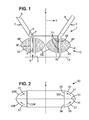
- the figure 1 is a cross-sectional view of a known speaker 1.
- This loudspeaker 1 comprises a fixed support 2, a mobile part 3 and an electrodynamic motor structure 10.
- the membrane 4 is integral with the mobile part 3. It is suspended from a support 2 by an external suspension 6 and an internal suspension 5, so that the mobile part 3 and the membrane 4 are movable and guided in translation in one direction Z axis, relative to the support 2.
- a coil 7 is further mounted on the mobile part 3.
- this coil 7 comprises an upper coil 7H and a lower coil 7L.
- the loudspeaker 1 also comprises an external magnetic element 8E and an internal magnetic element 81 integral with the support 2.
- These internal and external magnetic elements are annular magnets, coaxial along the Z axis and engaged one inside the other. . Between these magnetic elements, a cylindrical annular space 9 of axis Z is thus formed. The moving part 3 enters this annular space 9 and is able to move in said space 9 in the direction of the Z axis.
- the magnetic elements, external 8E and internal 81, are magnets. Their particular material generates a magnetic flux in their volume, represented in this figure by lines of magnetic field in dotted line in the section of these magnetic elements 8.
- the magnetic flux generated by the magnetic elements 8E, 81 then flows radially through the annular space 9.
- this magnetic flux is entering a lower portion of the front face 8F and is outgoing in an upper portion of the front face 8F.
- the magnetic flux is exiting in a lower portion of the front face 8F and is entering an upper portion of the front face 8F.
- the upper portions face the upper coil 7H
- the lower portions face the lower coil 7L.
- the magnetic flux in the space 9 is radial and directed outwards in a portion of the space in which the bottom coil 7L is located. It is radial and directed inwards in a portion of the space in which is the upper coil 7H.
- the upper and lower coils 7L, 7H are either connected to be fed with opposite currents or wound with opposite windings. They thus each induce a force F applied to the movable part 3 of the same Z axis direction.
- the ⁇ I or F is the force vector in the space applied to the moving part 3
- B is the vector of magnetic induction generated from the magnetic flux in the portion of space 9 considered
- I is the electric current vector in the coil of said portion of space 9
- L is the wire length of the coil in this portion of space.
- a variant of a loudspeaker 1 comprises an external magnetic element 8E, but does not include an internal magnetic element 81.
- an internal magnetic element 81 In place of this internal magnetic element 81, a tube made of ferrous material can take place to channel the flow magnetic from the upper portion to the lower portion. In this case, only the external magnetic element 8E generates the magnetic flux in the annular space 9.
- a loudspeaker 1 comprises an internal magnetic element 81, but does not include an external magnetic element 8E.
- a tube made of ferrous material can take place to channel the magnetic flux from the upper portion to the lower portion. In this case, only the internal magnetic element 81 generates the magnetic flux in the annular space 9.
- the magnetic elements 8E, 81 have the particularity of having an internal magnetic flux that has curved magnetic field lines, in particular the latter turning around between the lower portion of the front face 8F and the upper portion of the front face 8F.
- a molded magnet 30 by assembling at least two magnetic parts, that is to say assembling a first body section comprising the upper portion of the body. the front face and a second body section comprising the lower portion of the front face.
- the molded magnet 30 comprises a first body section 31 and a second body section 32.
- the first body portion 31 is thus a torus of axis of revolution Z, with a quarter-disc cross section.
- This first body portion 31 is a permanent magnet which produces a magnetic flux represented by the arrow, this magnetic flux describing inside the volume of the first body section 31 of the field lines curvilinear from the first face 33 to the second face 35.
- the second face 36 intersects the first face 34, signifies that these two faces are not parallel, and have at least one common edge. These faces form a predetermined angle between them.
- the predetermined angle may be 90 °, as shown in FIG. figure 2 , or a value greater than 90 °, or a value less than 90 °.
- first and second faces may be connected together by a chamfer or a radius of curvature, without this affecting the magnetic fields created. In such a case, it is more exactly the extensions of each of the intersecting faces. However, the predetermined angle between the two faces must remain significant and the virtual intersection line relatively close to the ends of the faces to obtain curved field lines.
- the predetermined angle may be 90 ° to form a magnet molded by assembling two body sections, i.e. two half-bodies 31, 32.
- the predetermined angle may be 60 °, to form a molded magnet 30 of the type of that of the figure 2 by assembling three body sections.
- the predetermined angle may be between 30 and 120 °, and preferably 90 °, to limit the number of body sections needed to form the molded magnet 30.
- the second body portion 32 is also a torus with an axis of revolution Z, with a quarter-disc cross section.
- This second body section 32 is a permanent magnet which produces a magnetic flux represented by the arrow, this magnetic flux describing inside the volume of the second body section 32 curvilinear field lines starting from the second face 36 towards the first face 34.
- the second faces 35, 36 of the first and second body sections are advantageously cylinders of the same diameter.
- the first and second body sections 31, 32 are assembled one on the other, by contacting the first face 33 of the first body section 31 with the first face 34 of the second body section 32, the second faces 35 , 36 thus forming a single cylindrical front face 30F of the molded magnet 30, and the first two faces 33, 34 forming a joint plane 25 of the molded magnet 30, as shown in FIG. figure 2 .
- the first and second body sections 31, 32 comprise on their respective first face pairs of complementary reliefs 33a, 34a and 33b, 34b.
- this relief 33a is an outgrowth.
- this relief 34a is a hollow.
- Each body section may have a plurality of reliefs, for example alternately outgrowth and recess.
- these protruding reliefs 33a are substantially conical pins.
- the recessed reliefs 33b are conical depressions of the same geometry. They are therefore adapted to each other.
- first body portion 31 When the first body portion 31 is assembled with the second body portion 32, these complementary reliefs position or center the body sections relative to each other.
- the second faces 35, 36 of the first and second body sections can thus be aligned correctly with respect to each other. These second faces then form a single front face 30F of the molded magnet 30.
- the first body portion 31 comprises a relief 33c protruding from its first face, said relief having a circular shape centered Z axis.
- the second body portion 32 comprises a recessed relief 34c of the same geometry, having a circular shape centered Z axis.
- the third peripheral faces 37, 38 can take a multitude of forms.
- the cross section may be square or rectangular or include, for example, lateral protrusions for integrating fasteners.
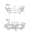
- the molded magnet 30 is produced according to the method comprising successive or simultaneous molding operations a), then at least one assembly operation b).
- the molding production operations a) comprise the production of a first and a second magnetic body section 31, 32.
- the cavity 43 of the molding device 40 comprises at least a first substantially flat face 41 and a second face 42 intersecting the first face 41 at a predetermined angle. They are for example substantially perpendicular.
- the magnetic flux is generated in step a2) by a magnetization device 44 adapted so that the magnetic flux passes through the cavity 43 along curvilinear field lines extending between the first and second faces.
- the magnetic field lines are then substantially perpendicular to the first face in its vicinity and perpendicular to the second face to its vicinity.
- the body portion 31, 32 made in step a3) has the shape of the cavity 43 and comprises a corresponding first and second face (33, 35, 34, 36) of the first and second faces (41, 42) of the cavity 43.
- the mixture used in this process can for example be made cold, then heated to a predetermined temperature so that the binder is in a plastic state.
- the binder may already be in a plastic state, for example by heating to a predetermined temperature, and then a magnetizable charge is then mixed with said binder in its plastic state.
- plastic state here is understood any suitable state so that the mixture can be injected into the cavity of the molding device 40. This can be a viscous or fluid state.
- the binder may be a polymer or a thermoplastic polymer.
- a thermoplastic polymer is inexpensive, and has a good fluidity when heated, which makes it possible to obtain a homogeneous mixture, easy shaping of this mixture in the molding device 40, and good mobility of the load mixed in the binder when the magnetic flux is applied to step a2) of the process.
- the magnetizable filler can thus also be oriented in the binder.
- the magnetizable filler may, for example, comprise particles of a magnetic material of the ferrite, Neodymium Iron Boron or Samarium Cobalt type. This magnetizable filler is advantageously a powder of these materials, or a mixture of these materials.
- the first and second body sections have been magnetically polarized by step a2), so that the first face 34 of the second body section 32 is of polarity. magnetic opposed to the first face 33 of the first body portion 31, and these faces are naturally magnetically attracted to each other.
- the joining of the first and second body sections 31, 32 can be achieved by any technique.
- the first faces 33, 34 can be glued or welded. In particular, they can be welded by welding located at the periphery of the first faces and the joint plane 25. Then, this weld does not modify the properties or magnetic characteristics of the two body sections 31, 32 of the molded magnet 30.
- the second face 42 is substantially perpendicular to the first face 41, of such that in each body section the magnetic field lines scan an angle of substantially 90 °, the predetermined angle, and that two body sections are sufficient to provide a magnet having magnetic field lines that scan an angle of substantially 180 °. °.
- the first and second body sections 31, 32 may have clipping or fixing members on one another, said members being for example located at the periphery of the joint plane 25.
- the first and second body portions 31, 32 may also be molded, thereby forming a connecting piece 39 that joins said body sections together.
- This connecting piece 39 comprises fixing members 39a, such as bores, adapted to fix the molded magnet 30 made.
- fixing members 39a such as bores
- these fasteners 39a serve to fix the molded magnet 30 to a support.
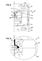
- This injection press is equipped with a lower die 46a and an upper die 47a comprising said channel 49.
- the cavity 43 for molding the body section is formed between the lower and upper die.
- the molding device 40 also comprises a magnetization device 44.
- the lower and upper plate here each comprise a coil 44a, 44b adapted to generate the magnetic flux. This flow is conducted through these trays and the dies to properly traverse the cavity 43 of the first face 41 to the second face 42, or vice versa.
- the trays, dies and columns of the molding device 40 thus form a magnetic circuit.
- These elements comprise parts having portions of magnetic material and other portions of non-magnetic material so that the flow is properly conducted to and through the cavity 43.
- the portions in contact with the first and second faces 41, 42 must be in a magnetic material (adapted to conduct a magnetic flux) while the portions in contact with the third face 37, 38 of the body section must preferably be of a non-magnetic material (adapted to not conduct or be resistant to a flow magnetic).
- the arrows represented in figure 8 and 9 show a possible path of the magnetic flux, this one crossing portions of parts of the molding device of magnetic material.
- the magnetization device 40 may be housed in the dies, such that it is adapted to cavity type.
- the lower die 46a and the upper die 47a each comprise a coil for generating the magnetic flux.
- the coils 44a, 44b are fed with an electric current to generate the magnetic flux in the molding device 40.
- the first and second sections 31, 32 to be magnetized in opposite ways from one another can be made by supplying the coil or coils of the magnetization device 44 with a current in a first direction
- the second body section 32 can be made by supplying the coil or coils of the magnetization device 44 with a current in a second direction opposite the first direction.
- First and second body sections 31, 32 are thus obtained with a single molding device 40.
- the magnetizer 44 may comprise permanent magnets or a combination of permanent magnets and coils to generate the magnetic flux of process step a2).
- the molding device 40 comprises two cavities for simultaneously producing the first and second body sections 31, 32.
- the molding device 40 comprises an interface plate (not shown) in contact with the first face of the first cavity and the first face of the second cavity.
- This plate is made of a material adapted to channel the magnetic flux of the device of magnetization 44.
- the magnetic flux of this magnetization device 44 is channeled from the first cavity to the second cavity, the two cavities being substantially stacked one above the other along the Z axis, and the first and second cavities.
- second body sections 31, 32 are made with the same magnetic flux.
- pairs of body sections 31, 32 made with a substantially identical magnetic flux. These body sections then have similar magnetic properties, and these two body sections can be advantageously assembled to form a molded magnet 30. Thanks to this arrangement, it is also possible to produce a larger quantity of body sections in the same cycle of the body. process.
- the molding device comprises a magnetic circuit adapted to separate the magnetic flux in a first and second flow.
- the first flow passes through a first cavity to make a first body 31, and the second flow passes through a second cavity to produce a second body section 32.
- a magnetization operation may be added after the assembly operation to give the molded magnet desired magnetic characteristics.
- a monopolar or multipolar magnet with a plurality of magnetic poles.
- the variants and embodiments described are in no way limiting. It is in particular possible to produce an annular molded magnet as described above, but it is also possible to produce a rectilinear molded magnet or having any predetermined profile.
- the magnet or magnetic element will consist of a first and a second body section, the magnetic field lines being bent in each body section to go from a first face to a second face.
- the invention can be applied to a loudspeaker, a vibratory pot, a linear motor, an actuator, a magnetic bearing, that is to say any electromechanical device comprising an electrodynamic motor that is geometry cylindrical, rectilinear or other.
Landscapes
- Engineering & Computer Science (AREA)
- Power Engineering (AREA)
- Manufacturing & Machinery (AREA)
- Physics & Mathematics (AREA)
- Electromagnetism (AREA)
- Manufacturing Cores, Coils, And Magnets (AREA)
Applications Claiming Priority (1)
| Application Number | Priority Date | Filing Date | Title |
|---|---|---|---|
| FR0959204A FR2954574B1 (fr) | 2009-12-18 | 2009-12-18 | Procede de fabrication d'un aimant moule. |
Publications (3)
| Publication Number | Publication Date |
|---|---|
| EP2337037A2 true EP2337037A2 (de) | 2011-06-22 |
| EP2337037A3 EP2337037A3 (de) | 2014-09-10 |
| EP2337037B1 EP2337037B1 (de) | 2016-02-10 |
Family
ID=41818928
Family Applications (1)
| Application Number | Title | Priority Date | Filing Date |
|---|---|---|---|
| EP10194483.3A Not-in-force EP2337037B1 (de) | 2009-12-18 | 2010-12-10 | Verfahren zur Herstellung eines gegossenen Magnetes |
Country Status (2)
| Country | Link |
|---|---|
| EP (1) | EP2337037B1 (de) |
| FR (1) | FR2954574B1 (de) |
Families Citing this family (1)
| Publication number | Priority date | Publication date | Assignee | Title |
|---|---|---|---|---|
| CN107105374B (zh) * | 2017-04-27 | 2019-10-11 | 河南大学 | 一种能够减弱分振现象的电声换能器 |
Citations (1)
| Publication number | Priority date | Publication date | Assignee | Title |
|---|---|---|---|---|
| EP2114086A1 (de) | 2008-04-30 | 2009-11-04 | Renault S.A.S. | Wandlermotoranordnung mit eisenloser und leckfreier Spule |
Family Cites Families (2)
| Publication number | Priority date | Publication date | Assignee | Title |
|---|---|---|---|---|
| JP2816668B2 (ja) * | 1996-07-04 | 1998-10-27 | 愛知製鋼株式会社 | 磁気異方性樹脂結合型磁石の製造方法 |
| FR2892886B1 (fr) * | 2005-11-03 | 2008-01-25 | Bernard Richoux | Transducteur electrodynamique, applications aux haut-parleurs et geophones |
-
2009
- 2009-12-18 FR FR0959204A patent/FR2954574B1/fr not_active Expired - Fee Related
-
2010
- 2010-12-10 EP EP10194483.3A patent/EP2337037B1/de not_active Not-in-force
Patent Citations (1)
| Publication number | Priority date | Publication date | Assignee | Title |
|---|---|---|---|---|
| EP2114086A1 (de) | 2008-04-30 | 2009-11-04 | Renault S.A.S. | Wandlermotoranordnung mit eisenloser und leckfreier Spule |
Also Published As
| Publication number | Publication date |
|---|---|
| FR2954574B1 (fr) | 2014-08-08 |
| EP2337037A3 (de) | 2014-09-10 |
| EP2337037B1 (de) | 2016-02-10 |
| FR2954574A1 (fr) | 2011-06-24 |
Similar Documents
| Publication | Publication Date | Title |
|---|---|---|
| FR2730874A1 (fr) | Inducteur composite pour machines tournantes electriques comportant des aimants permanents frittes enrobes dans un liant ferromagnetique | |
| FR2785105A1 (fr) | Moteur dans lequel sont encastres des aimants permanents et procede de fabrication du moteur | |
| EP2608226A1 (de) | Elektromagnetischer Aktuator mit magnetisierbarer Gleithülse | |
| FR2996378A1 (fr) | Rotor pour machine electrique | |
| EP1521352B1 (de) | Aktive Schwingungsdämpfungsvorrichtung eines Schwingungselementes | |
| EP1525062A1 (de) | Verfahren zur herstellung eines werkzeugs zum formen von werkstoff und danach hergestelltes werkzeug | |
| EP3061103A1 (de) | Elektromagnetischer aktuator und verfahren zur herstellung solch eines aktuators | |
| FR3011697A1 (fr) | Machine electrique sans encoches a bobinage concentre | |
| EP2337037B1 (de) | Verfahren zur Herstellung eines gegossenen Magnetes | |
| WO2023274890A1 (fr) | Procede de fabrication d'un element a poles magnetiques | |
| WO2024208570A1 (fr) | Pièce en matériau smc (soft magnetic composite) ou ferrite, installée autour des dents d'une machine électrique. | |
| WO2011098731A1 (fr) | Structure de transducteur electrodynamique et son procede de fabrication | |
| FR2996377A1 (fr) | Rotor pour machine electrique | |
| WO2020094574A1 (fr) | Rotor a cage d'ecureuil et machine electrique asynchrone comprotant un tel rotor | |
| FR3034587B1 (fr) | Procede de fabrication d'un rotor d'un moteur synchrone sans balais a concentration de flux. | |
| WO2012080586A1 (fr) | Stator pour génératrice électrique | |
| EP2534851B1 (de) | Magnetischer elektrodynamischer wandlermotor | |
| FR2835661A1 (fr) | Stator de moteur pas a pas | |
| FR2946811A1 (fr) | Stator pour generatrice electrique | |
| FR3113988A1 (fr) | Dispositif pour la formation de poles d’un rotor | |
| CH713235A2 (fr) | Bobine pour pompe électromagnétique, pompe électromagnétique, procédé de fabrication de bobine et kit de montage de pompe électromagnétique. | |
| WO2025162855A1 (fr) | Stator de machine électrique et procédé de fabrication d'un tel stator | |
| FR2971385A1 (fr) | Dispositif de moteur magnetique de transducteur electrodynamique | |
| EP4447276A1 (de) | Elektrische maschine mit erleichterter permanentmagnetextraktion und werkzeug zur extraktion | |
| FR3146247A1 (fr) | Montage réversible d’aimant permanent dans une machine électrique |
Legal Events
| Date | Code | Title | Description |
|---|---|---|---|
| PUAI | Public reference made under article 153(3) epc to a published international application that has entered the european phase |
Free format text: ORIGINAL CODE: 0009012 |
|
| AK | Designated contracting states |
Kind code of ref document: A2 Designated state(s): AL AT BE BG CH CY CZ DE DK EE ES FI FR GB GR HR HU IE IS IT LI LT LU LV MC MK MT NL NO PL PT RO RS SE SI SK SM TR |
|
| AX | Request for extension of the european patent |
Extension state: BA ME |
|
| PUAL | Search report despatched |
Free format text: ORIGINAL CODE: 0009013 |
|
| AK | Designated contracting states |
Kind code of ref document: A3 Designated state(s): AL AT BE BG CH CY CZ DE DK EE ES FI FR GB GR HR HU IE IS IT LI LT LU LV MC MK MT NL NO PL PT RO RS SE SI SK SM TR |
|
| AX | Request for extension of the european patent |
Extension state: BA ME |
|
| RIC1 | Information provided on ipc code assigned before grant |
Ipc: H04R 9/02 20060101ALI20140805BHEP Ipc: H01F 7/02 20060101AFI20140805BHEP Ipc: H01F 41/02 20060101ALI20140805BHEP |
|
| 17P | Request for examination filed |
Effective date: 20150211 |
|
| RBV | Designated contracting states (corrected) |
Designated state(s): AL AT BE BG CH CY CZ DE DK EE ES FI FR GB GR HR HU IE IS IT LI LT LU LV MC MK MT NL NO PL PT RO RS SE SI SK SM TR |
|
| GRAP | Despatch of communication of intention to grant a patent |
Free format text: ORIGINAL CODE: EPIDOSNIGR1 |
|
| INTG | Intention to grant announced |
Effective date: 20150826 |
|
| GRAS | Grant fee paid |
Free format text: ORIGINAL CODE: EPIDOSNIGR3 |
|
| GRAA | (expected) grant |
Free format text: ORIGINAL CODE: 0009210 |
|
| AK | Designated contracting states |
Kind code of ref document: B1 Designated state(s): AL AT BE BG CH CY CZ DE DK EE ES FI FR GB GR HR HU IE IS IT LI LT LU LV MC MK MT NL NO PL PT RO RS SE SI SK SM TR |
|
| REG | Reference to a national code |
Ref country code: GB Ref legal event code: FG4D Free format text: NOT ENGLISH |
|
| REG | Reference to a national code |
Ref country code: AT Ref legal event code: REF Ref document number: 775008 Country of ref document: AT Kind code of ref document: T Effective date: 20160215 Ref country code: CH Ref legal event code: EP |
|
| REG | Reference to a national code |
Ref country code: IE Ref legal event code: FG4D Free format text: LANGUAGE OF EP DOCUMENT: FRENCH |
|
| REG | Reference to a national code |
Ref country code: DE Ref legal event code: R096 Ref document number: 602010030520 Country of ref document: DE |
|
| REG | Reference to a national code |
Ref country code: LT Ref legal event code: MG4D |
|
| REG | Reference to a national code |
Ref country code: NL Ref legal event code: MP Effective date: 20160210 |
|
| REG | Reference to a national code |
Ref country code: AT Ref legal event code: MK05 Ref document number: 775008 Country of ref document: AT Kind code of ref document: T Effective date: 20160210 |
|
| PG25 | Lapsed in a contracting state [announced via postgrant information from national office to epo] |
Ref country code: HR Free format text: LAPSE BECAUSE OF FAILURE TO SUBMIT A TRANSLATION OF THE DESCRIPTION OR TO PAY THE FEE WITHIN THE PRESCRIBED TIME-LIMIT Effective date: 20160210 Ref country code: ES Free format text: LAPSE BECAUSE OF FAILURE TO SUBMIT A TRANSLATION OF THE DESCRIPTION OR TO PAY THE FEE WITHIN THE PRESCRIBED TIME-LIMIT Effective date: 20160210 Ref country code: GR Free format text: LAPSE BECAUSE OF FAILURE TO SUBMIT A TRANSLATION OF THE DESCRIPTION OR TO PAY THE FEE WITHIN THE PRESCRIBED TIME-LIMIT Effective date: 20160511 Ref country code: NO Free format text: LAPSE BECAUSE OF FAILURE TO SUBMIT A TRANSLATION OF THE DESCRIPTION OR TO PAY THE FEE WITHIN THE PRESCRIBED TIME-LIMIT Effective date: 20160510 Ref country code: FI Free format text: LAPSE BECAUSE OF FAILURE TO SUBMIT A TRANSLATION OF THE DESCRIPTION OR TO PAY THE FEE WITHIN THE PRESCRIBED TIME-LIMIT Effective date: 20160210 |
|
| PG25 | Lapsed in a contracting state [announced via postgrant information from national office to epo] |
Ref country code: PL Free format text: LAPSE BECAUSE OF FAILURE TO SUBMIT A TRANSLATION OF THE DESCRIPTION OR TO PAY THE FEE WITHIN THE PRESCRIBED TIME-LIMIT Effective date: 20160210 Ref country code: IS Free format text: LAPSE BECAUSE OF FAILURE TO SUBMIT A TRANSLATION OF THE DESCRIPTION OR TO PAY THE FEE WITHIN THE PRESCRIBED TIME-LIMIT Effective date: 20160610 Ref country code: LV Free format text: LAPSE BECAUSE OF FAILURE TO SUBMIT A TRANSLATION OF THE DESCRIPTION OR TO PAY THE FEE WITHIN THE PRESCRIBED TIME-LIMIT Effective date: 20160210 Ref country code: NL Free format text: LAPSE BECAUSE OF FAILURE TO SUBMIT A TRANSLATION OF THE DESCRIPTION OR TO PAY THE FEE WITHIN THE PRESCRIBED TIME-LIMIT Effective date: 20160210 Ref country code: SE Free format text: LAPSE BECAUSE OF FAILURE TO SUBMIT A TRANSLATION OF THE DESCRIPTION OR TO PAY THE FEE WITHIN THE PRESCRIBED TIME-LIMIT Effective date: 20160210 Ref country code: RS Free format text: LAPSE BECAUSE OF FAILURE TO SUBMIT A TRANSLATION OF THE DESCRIPTION OR TO PAY THE FEE WITHIN THE PRESCRIBED TIME-LIMIT Effective date: 20160210 Ref country code: LT Free format text: LAPSE BECAUSE OF FAILURE TO SUBMIT A TRANSLATION OF THE DESCRIPTION OR TO PAY THE FEE WITHIN THE PRESCRIBED TIME-LIMIT Effective date: 20160210 Ref country code: PT Free format text: LAPSE BECAUSE OF FAILURE TO SUBMIT A TRANSLATION OF THE DESCRIPTION OR TO PAY THE FEE WITHIN THE PRESCRIBED TIME-LIMIT Effective date: 20160613 Ref country code: AT Free format text: LAPSE BECAUSE OF FAILURE TO SUBMIT A TRANSLATION OF THE DESCRIPTION OR TO PAY THE FEE WITHIN THE PRESCRIBED TIME-LIMIT Effective date: 20160210 |
|
| PG25 | Lapsed in a contracting state [announced via postgrant information from national office to epo] |
Ref country code: DK Free format text: LAPSE BECAUSE OF FAILURE TO SUBMIT A TRANSLATION OF THE DESCRIPTION OR TO PAY THE FEE WITHIN THE PRESCRIBED TIME-LIMIT Effective date: 20160210 Ref country code: EE Free format text: LAPSE BECAUSE OF FAILURE TO SUBMIT A TRANSLATION OF THE DESCRIPTION OR TO PAY THE FEE WITHIN THE PRESCRIBED TIME-LIMIT Effective date: 20160210 |
|
| REG | Reference to a national code |
Ref country code: DE Ref legal event code: R097 Ref document number: 602010030520 Country of ref document: DE |
|
| PG25 | Lapsed in a contracting state [announced via postgrant information from national office to epo] |
Ref country code: CZ Free format text: LAPSE BECAUSE OF FAILURE TO SUBMIT A TRANSLATION OF THE DESCRIPTION OR TO PAY THE FEE WITHIN THE PRESCRIBED TIME-LIMIT Effective date: 20160210 Ref country code: RO Free format text: LAPSE BECAUSE OF FAILURE TO SUBMIT A TRANSLATION OF THE DESCRIPTION OR TO PAY THE FEE WITHIN THE PRESCRIBED TIME-LIMIT Effective date: 20160210 Ref country code: SK Free format text: LAPSE BECAUSE OF FAILURE TO SUBMIT A TRANSLATION OF THE DESCRIPTION OR TO PAY THE FEE WITHIN THE PRESCRIBED TIME-LIMIT Effective date: 20160210 Ref country code: SM Free format text: LAPSE BECAUSE OF FAILURE TO SUBMIT A TRANSLATION OF THE DESCRIPTION OR TO PAY THE FEE WITHIN THE PRESCRIBED TIME-LIMIT Effective date: 20160210 |
|
| PLBE | No opposition filed within time limit |
Free format text: ORIGINAL CODE: 0009261 |
|
| STAA | Information on the status of an ep patent application or granted ep patent |
Free format text: STATUS: NO OPPOSITION FILED WITHIN TIME LIMIT |
|
| REG | Reference to a national code |
Ref country code: FR Ref legal event code: PLFP Year of fee payment: 7 |
|
| 26N | No opposition filed |
Effective date: 20161111 |
|
| PG25 | Lapsed in a contracting state [announced via postgrant information from national office to epo] |
Ref country code: BG Free format text: LAPSE BECAUSE OF FAILURE TO SUBMIT A TRANSLATION OF THE DESCRIPTION OR TO PAY THE FEE WITHIN THE PRESCRIBED TIME-LIMIT Effective date: 20160510 Ref country code: SI Free format text: LAPSE BECAUSE OF FAILURE TO SUBMIT A TRANSLATION OF THE DESCRIPTION OR TO PAY THE FEE WITHIN THE PRESCRIBED TIME-LIMIT Effective date: 20160210 |
|
| PG25 | Lapsed in a contracting state [announced via postgrant information from national office to epo] |
Ref country code: BE Free format text: LAPSE BECAUSE OF NON-PAYMENT OF DUE FEES Effective date: 20161231 |
|
| REG | Reference to a national code |
Ref country code: CH Ref legal event code: PL |
|
| PG25 | Lapsed in a contracting state [announced via postgrant information from national office to epo] |
Ref country code: MC Free format text: LAPSE BECAUSE OF FAILURE TO SUBMIT A TRANSLATION OF THE DESCRIPTION OR TO PAY THE FEE WITHIN THE PRESCRIBED TIME-LIMIT Effective date: 20160210 |
|
| REG | Reference to a national code |
Ref country code: IE Ref legal event code: MM4A |
|
| PG25 | Lapsed in a contracting state [announced via postgrant information from national office to epo] |
Ref country code: CH Free format text: LAPSE BECAUSE OF NON-PAYMENT OF DUE FEES Effective date: 20161231 Ref country code: LI Free format text: LAPSE BECAUSE OF NON-PAYMENT OF DUE FEES Effective date: 20161231 Ref country code: LU Free format text: LAPSE BECAUSE OF NON-PAYMENT OF DUE FEES Effective date: 20161210 |
|
| PG25 | Lapsed in a contracting state [announced via postgrant information from national office to epo] |
Ref country code: IE Free format text: LAPSE BECAUSE OF NON-PAYMENT OF DUE FEES Effective date: 20161210 |
|
| REG | Reference to a national code |
Ref country code: FR Ref legal event code: PLFP Year of fee payment: 8 |
|
| PGFP | Annual fee paid to national office [announced via postgrant information from national office to epo] |
Ref country code: DE Payment date: 20171212 Year of fee payment: 8 Ref country code: FR Payment date: 20171220 Year of fee payment: 8 |
|
| REG | Reference to a national code |
Ref country code: BE Ref legal event code: MM Effective date: 20161231 |
|
| PGFP | Annual fee paid to national office [announced via postgrant information from national office to epo] |
Ref country code: IT Payment date: 20171215 Year of fee payment: 8 Ref country code: GB Payment date: 20171219 Year of fee payment: 8 |
|
| PG25 | Lapsed in a contracting state [announced via postgrant information from national office to epo] |
Ref country code: HU Free format text: LAPSE BECAUSE OF FAILURE TO SUBMIT A TRANSLATION OF THE DESCRIPTION OR TO PAY THE FEE WITHIN THE PRESCRIBED TIME-LIMIT; INVALID AB INITIO Effective date: 20101210 Ref country code: CY Free format text: LAPSE BECAUSE OF FAILURE TO SUBMIT A TRANSLATION OF THE DESCRIPTION OR TO PAY THE FEE WITHIN THE PRESCRIBED TIME-LIMIT Effective date: 20160210 |
|
| PG25 | Lapsed in a contracting state [announced via postgrant information from national office to epo] |
Ref country code: MK Free format text: LAPSE BECAUSE OF FAILURE TO SUBMIT A TRANSLATION OF THE DESCRIPTION OR TO PAY THE FEE WITHIN THE PRESCRIBED TIME-LIMIT Effective date: 20160210 Ref country code: TR Free format text: LAPSE BECAUSE OF FAILURE TO SUBMIT A TRANSLATION OF THE DESCRIPTION OR TO PAY THE FEE WITHIN THE PRESCRIBED TIME-LIMIT Effective date: 20160210 |
|
| PG25 | Lapsed in a contracting state [announced via postgrant information from national office to epo] |
Ref country code: MT Free format text: LAPSE BECAUSE OF FAILURE TO SUBMIT A TRANSLATION OF THE DESCRIPTION OR TO PAY THE FEE WITHIN THE PRESCRIBED TIME-LIMIT Effective date: 20160210 |
|
| PG25 | Lapsed in a contracting state [announced via postgrant information from national office to epo] |
Ref country code: AL Free format text: LAPSE BECAUSE OF FAILURE TO SUBMIT A TRANSLATION OF THE DESCRIPTION OR TO PAY THE FEE WITHIN THE PRESCRIBED TIME-LIMIT Effective date: 20160210 |
|
| REG | Reference to a national code |
Ref country code: DE Ref legal event code: R119 Ref document number: 602010030520 Country of ref document: DE |
|
| GBPC | Gb: european patent ceased through non-payment of renewal fee |
Effective date: 20181210 |
|
| PG25 | Lapsed in a contracting state [announced via postgrant information from national office to epo] |
Ref country code: FR Free format text: LAPSE BECAUSE OF NON-PAYMENT OF DUE FEES Effective date: 20181231 Ref country code: DE Free format text: LAPSE BECAUSE OF NON-PAYMENT OF DUE FEES Effective date: 20190702 Ref country code: IT Free format text: LAPSE BECAUSE OF NON-PAYMENT OF DUE FEES Effective date: 20181210 |
|
| PG25 | Lapsed in a contracting state [announced via postgrant information from national office to epo] |
Ref country code: GB Free format text: LAPSE BECAUSE OF NON-PAYMENT OF DUE FEES Effective date: 20181210 |