EP2337005A1 - Simulateur de force centrifuge pour parapente - Google Patents
Simulateur de force centrifuge pour parapente Download PDFInfo
- Publication number
- EP2337005A1 EP2337005A1 EP10190022A EP10190022A EP2337005A1 EP 2337005 A1 EP2337005 A1 EP 2337005A1 EP 10190022 A EP10190022 A EP 10190022A EP 10190022 A EP10190022 A EP 10190022A EP 2337005 A1 EP2337005 A1 EP 2337005A1
- Authority
- EP
- European Patent Office
- Prior art keywords
- pilot
- suspension
- centrifugal force
- pivoting
- simulator
- Prior art date
- Legal status (The legal status is an assumption and is not a legal conclusion. Google has not performed a legal analysis and makes no representation as to the accuracy of the status listed.)
- Withdrawn
Links
Images


Classifications
-
- G—PHYSICS
- G09—EDUCATION; CRYPTOGRAPHY; DISPLAY; ADVERTISING; SEALS
- G09B—EDUCATIONAL OR DEMONSTRATION APPLIANCES; APPLIANCES FOR TEACHING, OR COMMUNICATING WITH, THE BLIND, DEAF OR MUTE; MODELS; PLANETARIA; GLOBES; MAPS; DIAGRAMS
- G09B9/00—Simulators for teaching or training purposes
- G09B9/02—Simulators for teaching or training purposes for teaching control of vehicles or other craft
- G09B9/08—Simulators for teaching or training purposes for teaching control of vehicles or other craft for teaching control of aircraft, e.g. Link trainer
- G09B9/10—Simulators for teaching or training purposes for teaching control of vehicles or other craft for teaching control of aircraft, e.g. Link trainer with simulated flight- or engine-generated force being applied to aircraft occupant
-
- G—PHYSICS
- G09—EDUCATION; CRYPTOGRAPHY; DISPLAY; ADVERTISING; SEALS
- G09B—EDUCATIONAL OR DEMONSTRATION APPLIANCES; APPLIANCES FOR TEACHING, OR COMMUNICATING WITH, THE BLIND, DEAF OR MUTE; MODELS; PLANETARIA; GLOBES; MAPS; DIAGRAMS
- G09B9/00—Simulators for teaching or training purposes
-
- G—PHYSICS
- G09—EDUCATION; CRYPTOGRAPHY; DISPLAY; ADVERTISING; SEALS
- G09B—EDUCATIONAL OR DEMONSTRATION APPLIANCES; APPLIANCES FOR TEACHING, OR COMMUNICATING WITH, THE BLIND, DEAF OR MUTE; MODELS; PLANETARIA; GLOBES; MAPS; DIAGRAMS
- G09B9/00—Simulators for teaching or training purposes
- G09B9/02—Simulators for teaching or training purposes for teaching control of vehicles or other craft
- G09B9/08—Simulators for teaching or training purposes for teaching control of vehicles or other craft for teaching control of aircraft, e.g. Link trainer
Definitions
- the invention relates to a training and training device for the paragliding (paragliding), that allows the pilot to get used in a very realistic manner to the occurring g-loads (centrifugal forces) during maneuvers in paragliding, to train them and safely the body to introduce these forces and visual impressions.
- Paragliding or paragliding is a flying sport in which the pilot can take a paraglider from a mountain and, using dynamic or thermal wind-ups without an engine, can be in the air for up to several hours, covering distances of more than 100 km.
- the paraglider Due to its low airspeed, the paraglider is a very agile aircraft, but also susceptible to weather changes. Wind speeds of 30 km / h, for many aircraft no problem, are already considered borderline for the paraglider.
- a paragliding flight simulator emerges, consisting essentially of three components that move relative to each other.
- a fixed ceiling anchorage including a rotating structure that can rotate the pilot 360 ° along its vertical axis (Z-axis), a slide that can perform linear reciprocating movements back and forth, and a balance device, the pilot at Bremsleinenyak tends to increase by raising the seatboard of the harness via motors.
- the body is brought "stationary" in an inclined position, but the forces occurring on the pilot body do not correspond to the forces occurring during flight.
- the real flight behavior of a Paragleitles be simulated in the turn, ie the forward tilting of the body of the pilot in the spiral fall.
- a simulator training provides a significant increase in the effective training time compared to the time spent (about 1: 500 to 1: 1000 in real flight, and about 1:10 in simulator training).
- the cost of achieving the same training effect when comparing real flight and simulator training is about 5 to 10% on the simulator.
- a pilot can achieve an effective training time with some training sessions, which he would achieve with real flights usually only over several years.
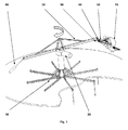
- the centrifugal simulator consists as in Fig.1 represented by the main components mounting frame (10), geared motor (20), rotor (30) connecting joint (40), coupling (50), pilot suspension (60), harness (70) and balance weight (80)
- the design of the speed of the rotor (30) and radius of the rotor (30) is chosen so that the product of radius and angular velocity, the centrifugal force, corresponds to those obtained in flight with the paraglider.
- the radius of the rotor (30) is less than the orbit radius in real flight, but the angular velocity of the geared motor (20) is greater. As a result, a smaller size of the centrifugal force simulator is achieved.
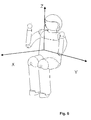
- the centrifugal force simulator is designed in such a way that the pilot, depending on the centrifugal force, occupies exactly the position in the space that he occupies during the flight. This is very important for the realistic simulation, since the centrifugal forces are divided into the three axes gx, gy and gz, which act along the axes x, y and z ( Fig. 6 ) have very different effects on the organism and therefore not only the resultant of these components may be considered but the direction of the individual components.
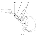
- a paraglider can be steered into a curve in two ways. Either by pulling on the control lines (61), or by shifting the center of gravity to one side. By this displacement, one of the two suspension points (65) moves upwards, the other down, the paraglider gets an asymmetric lift distribution and thereby rotates in the direction in which the center of gravity is shifted.
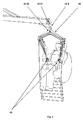
- the pilot suspension (60) is connected to the rotor (30) by the connecting joint (40).
- the lower bearing (40 X2) on the connecting joint (40) allows the pilot to apply the usual in-flight weight transfer to the centrifugal force simulator. This causes a substantial change in the distribution of the centrifugal force components gx, gy, and gz, which act on the body. Therefore, this is taken into account in the simulation. The resultant of the three g-components remains unchanged.
- each g-load is assigned a unique angle. (60 ° at 2 g, 90 ° would correspond to an infinite centrifugal force.)
- the rotation predominates around the longitudinal axis x of the pilot, at higher g loads, the pivotal movement about the vertical axis z of the pilot then predominates (view downwards).
- the pivoting of the pilot body about the longitudinal axis x in the storage (40 X1) is always smaller than 90 °, since 90 ° would correspond to a g-load of infinity.
- the rotation about the vertical axis z in the bearing (40Z) can be more than 90 °, the pilot then flies with the body in the spiral motion already with a backward component, which means the transition to the maneuver "SAT".
- a coupling (50) consisting of the coupling rod (51) and the coupling rod ( 52) between the rotor (30) and connecting joint (40) installed.
- the coupling causes the pilot body, which pivots outward with increasing rotation by the centrifugal force (40 X1), also pivots his gaze downward in flight.
- a change in the length of the coupling rod (51) and the coupling rod (52) and the angle between z-y plane of the pilot and the coupling rod (52) affects the interaction of the two rotational movements.
- the coupling of the two pivoting movements about the x- and z-axis of the pilot could also be realized by an electromechanical solution by means of servo motors and control technology.
- a paraglider has two so-called “brakes” or “steering lines” (61) to control it.
- the "control path” is the measure in centimeters how far the control line is pulled in. Basically, the brake force increase is in straight flight while pulling on the control lines (61) approximately linear, but slightly depending on the design features of the paraglider as well as the surface load (total weight relative to the projected wing)
- This braking force increase is realized by a Raffmati, in which a plurality of weights (62) are mounted one above the other and in each case the lowest weight is raised by train until it meets the next weight and this entrains.
- a stepped brake force increase is realized, but which is considered to be quasi-linear, since the human body can perceive the step-like increase in the load on the hand anyway.
- the simulation of the braking force increase with increasing control path could also be realized by an electromechanical solution by means of servo motors and control technology.
- the braking force increases with increasing g load.
- weights (62) By using weights (62) to simulate the braking force, braking force increase is achieved with increasing g-load since the same centrifugal force acts on the weights (62) as on the pilots. This would not be the case when using a spring.
- the simulation of the brake force increase with increasing g-load could also be realized by an electromechanical solution using actuators and control technology.
- the control lines (61) pass over deflection rollers (63), (64). On a pulley (64) a rotary potentiometer is attached, which provides the control signal for a frequency converter, which sets the geared motor (20) and thus the rotor (30) in rotation.
- a train at the Control line (61) causes the rotor (30) of the centrifugal force simulator to be accelerated and thereby the pilot is brought into the simulated position with corresponding g load.
- the braking force increases with increasing braking distance and increasing g-load.
- the centrifugal force simulator is able by the above-mentioned design details the position of the pilot according to the centrifugal force, the real flight according to realistic position. Only the radius and the angular velocity of the centrifugal simulator are changed in comparison to the real flight. The pilot also does not perform any real vertical movement on the centrifugal force simulator.
- the pilot does not see his immediate environment during training. He has a Virtual Reality Glasses (90), which contains two small high-resolution monitors and a corresponding optics.
- These virtual reality glasses (90) are equipped with infrared sensors, an already commercially available product, giving the pilot a virtual three-dimensional landscape. Due to the real situation, which are realized by the structural components of the centrifugal force simulator, the pilot now looks like in flight at the same angle on the landscape, as in flight.
- the receiver of the Virtual Reality glasses is located in the center of the centrifugal simulator. The slightly narrower radius on which the pilot rotates on the centrifugal simulator is irrelevant for the 3-d perception of his landscape.
- the receiver sensor of the virtual reality system is displaced about the z axis in the same direction as the rotor (30), so that the angular velocity between the pilot and the infrared receiver real angular velocity in flight equivalent.
- PC flight simulators which can also be operated with such virtual reality glasses.
- the landscape is displayed as a coordinate system and the movement in space only through the real movement of the Pilot on the centrifugal simulator results.
Applications Claiming Priority (1)
| Application Number | Priority Date | Filing Date | Title |
|---|---|---|---|
| AT18862009A AT509122B1 (de) | 2009-11-26 | 2009-11-26 | Fliehkraftsimulator für paragleiten |
Publications (1)
| Publication Number | Publication Date |
|---|---|
| EP2337005A1 true EP2337005A1 (fr) | 2011-06-22 |
Family
ID=43880977
Family Applications (1)
| Application Number | Title | Priority Date | Filing Date |
|---|---|---|---|
| EP10190022A Withdrawn EP2337005A1 (fr) | 2009-11-26 | 2010-11-04 | Simulateur de force centrifuge pour parapente |
Country Status (2)
| Country | Link |
|---|---|
| EP (1) | EP2337005A1 (fr) |
| AT (1) | AT509122B1 (fr) |
Cited By (5)
| Publication number | Priority date | Publication date | Assignee | Title |
|---|---|---|---|---|
| GB2487369B (en) * | 2011-01-18 | 2013-05-01 | Maelstrom Virtual Productions Ltd | Parachute training simulators |
| RU2538996C2 (ru) * | 2011-12-29 | 2015-01-10 | Федеральное государственное военное образовательное учреждение высшего профессионального образования "Военный учебно-научный центр Сухопутных войск Общевойсковая академия Вооруженных Сил Российской Федерации" | Тренажер парашютиста |
| KR20160001184A (ko) * | 2014-06-26 | 2016-01-06 | 주식회사 도담시스템스 | 패러글라이딩용 시뮬레이션 시스템 |
| RU2645516C2 (ru) * | 2016-05-16 | 2018-02-21 | Федеральное государственное казенное военное образовательное учреждение высшего профессионального образования Рязанское высшее воздушно-десантное командное училище (военный институт) имени генерала армии В.Ф. Маргелова МО РФ | Динамический тренажер применения парашютных систем типа "летающее крыло" |
| US10082439B1 (en) * | 2016-09-16 | 2018-09-25 | Rockwell Collins, Inc. | Event depiction on center of gravity curve |
Citations (6)
| Publication number | Priority date | Publication date | Assignee | Title |
|---|---|---|---|---|
| JPH08182788A (ja) * | 1994-12-28 | 1996-07-16 | Ishikawajima Harima Heavy Ind Co Ltd | スカイダイビング及びパラシュート降下訓練シミュレータ |
| JPH08244690A (ja) * | 1995-03-09 | 1996-09-24 | Ishikawajima Harima Heavy Ind Co Ltd | パラシュート操縦訓練用シミュレータ |
| JPH08244691A (ja) * | 1995-03-09 | 1996-09-24 | Ishikawajima Harima Heavy Ind Co Ltd | パラシュート操縦訓練用シミュレータ |
| WO2002076829A1 (fr) * | 2001-03-22 | 2002-10-03 | Sung Taee Lee | Simulateur de parachutisme et processus de formation au saut l'utilisant |
| DE102006015344A1 (de) * | 2006-04-03 | 2007-10-04 | Rüger, Ulrich, Dipl.-Ing. | Simulator für Gleitsegel oder Fallschirme |
| BRPI0700526A (pt) | 2007-02-23 | 2008-10-14 | Hans Heinrich Vogt | simulador de vÈo de parapente |
Family Cites Families (2)
| Publication number | Priority date | Publication date | Assignee | Title |
|---|---|---|---|---|
| SU355829A1 (ru) * | 1970-11-12 | 1980-06-15 | Nevskij Yu B | Устройство дл исследовани вли ни на человека перегрузок при вращении на центрифуге |
| JPH07334071A (ja) * | 1994-06-08 | 1995-12-22 | Shimadzu Corp | 遠心力発生装置およびその装置におけるアーム形状の決定方法 |
-
2009
- 2009-11-26 AT AT18862009A patent/AT509122B1/de not_active IP Right Cessation
-
2010
- 2010-11-04 EP EP10190022A patent/EP2337005A1/fr not_active Withdrawn
Patent Citations (6)
| Publication number | Priority date | Publication date | Assignee | Title |
|---|---|---|---|---|
| JPH08182788A (ja) * | 1994-12-28 | 1996-07-16 | Ishikawajima Harima Heavy Ind Co Ltd | スカイダイビング及びパラシュート降下訓練シミュレータ |
| JPH08244690A (ja) * | 1995-03-09 | 1996-09-24 | Ishikawajima Harima Heavy Ind Co Ltd | パラシュート操縦訓練用シミュレータ |
| JPH08244691A (ja) * | 1995-03-09 | 1996-09-24 | Ishikawajima Harima Heavy Ind Co Ltd | パラシュート操縦訓練用シミュレータ |
| WO2002076829A1 (fr) * | 2001-03-22 | 2002-10-03 | Sung Taee Lee | Simulateur de parachutisme et processus de formation au saut l'utilisant |
| DE102006015344A1 (de) * | 2006-04-03 | 2007-10-04 | Rüger, Ulrich, Dipl.-Ing. | Simulator für Gleitsegel oder Fallschirme |
| BRPI0700526A (pt) | 2007-02-23 | 2008-10-14 | Hans Heinrich Vogt | simulador de vÈo de parapente |
Cited By (5)
| Publication number | Priority date | Publication date | Assignee | Title |
|---|---|---|---|---|
| GB2487369B (en) * | 2011-01-18 | 2013-05-01 | Maelstrom Virtual Productions Ltd | Parachute training simulators |
| RU2538996C2 (ru) * | 2011-12-29 | 2015-01-10 | Федеральное государственное военное образовательное учреждение высшего профессионального образования "Военный учебно-научный центр Сухопутных войск Общевойсковая академия Вооруженных Сил Российской Федерации" | Тренажер парашютиста |
| KR20160001184A (ko) * | 2014-06-26 | 2016-01-06 | 주식회사 도담시스템스 | 패러글라이딩용 시뮬레이션 시스템 |
| RU2645516C2 (ru) * | 2016-05-16 | 2018-02-21 | Федеральное государственное казенное военное образовательное учреждение высшего профессионального образования Рязанское высшее воздушно-десантное командное училище (военный институт) имени генерала армии В.Ф. Маргелова МО РФ | Динамический тренажер применения парашютных систем типа "летающее крыло" |
| US10082439B1 (en) * | 2016-09-16 | 2018-09-25 | Rockwell Collins, Inc. | Event depiction on center of gravity curve |
Also Published As
| Publication number | Publication date |
|---|---|
| AT509122B1 (de) | 2012-01-15 |
| AT509122A1 (de) | 2011-06-15 |
Similar Documents
| Publication | Publication Date | Title |
|---|---|---|
| EP2715702B1 (fr) | Dispositif de déplacement spatial de personnes | |
| DE102009019628B4 (de) | Luftrettungs-Simulator | |
| EP2612311B1 (fr) | Dispositif et procédé pour faire fonctionner un simulateur de vol avec une impression de réalité exceptionnelle | |
| DE69910344T2 (de) | Cockpitanzeige mit dreidimensionaler Flugbahnabweichungssymbolik | |
| DE102012023925A1 (de) | Verfahren und Vorrichtung zum kombinierten Simulieren und Steuern ferngesteuerter Fahrzeuge mit einem benutzerfreundlichen Projektionssystem | |
| DE69628410T2 (de) | Verbesserter flugsimulator | |
| AT509122B1 (de) | Fliehkraftsimulator für paragleiten | |
| EP2235712A2 (fr) | Procédé servant à simuler des états de vol d'un aéronef pouvant décoller et/ou atterrir verticalement | |
| EP2920779A2 (fr) | Procédé et dispositif de simulation et de commande combinées de véhicules télécommandés | |
| DE102018103617B4 (de) | Trainingssimulator für ein Fluggerät | |
| CN112435528A (zh) | 伞降训练模拟系统及设备 | |
| DE10140676B4 (de) | Bahnführungs-Systeme für einen Fall- oder Gleitschirm und Flugbahn-Planungseinrichtungen zur Planung des Einsatzes zumindest eines Fall- oder Gleitschirms sowie Verfahren zur Durchführung der Bahnführung und der Planung | |
| DE202015104591U1 (de) | Hubschrauber mit mehreren Rotoren und variabler Blattsteigung | |
| DE202012011693U1 (de) | Vorrichtung zum kombinierten Simulieren und Steuern ferngesteuerter Fahrzeuge mit einem benutzerfreundlichen Projektionssystem | |
| EP3175436B1 (fr) | Appareil pour le mouvement spatial d'au moins une personne | |
| DE4138252A1 (de) | Vorrichtung und verfahren das mit hilfe der fliehkraft, eine subjektive simulation von kraeften erlaubt, die bei einer bewegung auf einen koerper einwirken | |
| DE4010375C2 (fr) | ||
| Groen et al. | Motion fidelity during a simulated takeoff | |
| DE102011105155B4 (de) | Vorrichtung und Verfahren zur dynamischen Einstellung einer Orientierung eines Flugzeugsitzes | |
| DE879964C (de) | Segelflugvorschulungsapparat | |
| Kron | Advanced Simulation in Undergraduate Pilot Training: Motion Systems Development | |
| Groen et al. | Pilot's Perception and Control Behavior During Simulated Take Off | |
| DE19640730A1 (de) | Flugsimulator | |
| TRAINING | S LABORATORY | |
| DE202012011015U1 (de) | Vorrichtung zum kombinierten Simulieren und Steuern ferngesteuerter Fahrzeuge |
Legal Events
| Date | Code | Title | Description |
|---|---|---|---|
| PUAI | Public reference made under article 153(3) epc to a published international application that has entered the european phase |
Free format text: ORIGINAL CODE: 0009012 |
|
| AK | Designated contracting states |
Kind code of ref document: A1 Designated state(s): AL AT BE BG CH CY CZ DE DK EE ES FI FR GB GR HR HU IE IS IT LI LT LU LV MC MK MT NL NO PL PT RO RS SE SI SK SM TR |
|
| AX | Request for extension of the european patent |
Extension state: BA ME |
|
| 17P | Request for examination filed |
Effective date: 20111210 |
|
| GRAP | Despatch of communication of intention to grant a patent |
Free format text: ORIGINAL CODE: EPIDOSNIGR1 |
|
| INTG | Intention to grant announced |
Effective date: 20170127 |
|
| STAA | Information on the status of an ep patent application or granted ep patent |
Free format text: STATUS: THE APPLICATION IS DEEMED TO BE WITHDRAWN |
|
| 18D | Application deemed to be withdrawn |
Effective date: 20170607 |