EP2336674A1 - Refrigeration cycle system and automotive air conditioning system using said refrigeration cycle system - Google Patents
Refrigeration cycle system and automotive air conditioning system using said refrigeration cycle system Download PDFInfo
- Publication number
- EP2336674A1 EP2336674A1 EP09822113A EP09822113A EP2336674A1 EP 2336674 A1 EP2336674 A1 EP 2336674A1 EP 09822113 A EP09822113 A EP 09822113A EP 09822113 A EP09822113 A EP 09822113A EP 2336674 A1 EP2336674 A1 EP 2336674A1
- Authority
- EP
- European Patent Office
- Prior art keywords
- condenser
- lubricant
- refrigerant
- refrigeration cycle
- compressor
- Prior art date
- Legal status (The legal status is an assumption and is not a legal conclusion. Google has not performed a legal analysis and makes no representation as to the accuracy of the status listed.)
- Withdrawn
Links
Images


Classifications
-
- F—MECHANICAL ENGINEERING; LIGHTING; HEATING; WEAPONS; BLASTING
- F25—REFRIGERATION OR COOLING; COMBINED HEATING AND REFRIGERATION SYSTEMS; HEAT PUMP SYSTEMS; MANUFACTURE OR STORAGE OF ICE; LIQUEFACTION SOLIDIFICATION OF GASES
- F25B—REFRIGERATION MACHINES, PLANTS OR SYSTEMS; COMBINED HEATING AND REFRIGERATION SYSTEMS; HEAT PUMP SYSTEMS
- F25B9/00—Compression machines, plants or systems, in which the refrigerant is air or other gas of low boiling point
- F25B9/002—Compression machines, plants or systems, in which the refrigerant is air or other gas of low boiling point characterised by the refrigerant
-
- B—PERFORMING OPERATIONS; TRANSPORTING
- B60—VEHICLES IN GENERAL
- B60H—ARRANGEMENTS OF HEATING, COOLING, VENTILATING OR OTHER AIR-TREATING DEVICES SPECIALLY ADAPTED FOR PASSENGER OR GOODS SPACES OF VEHICLES
- B60H1/00—Heating, cooling or ventilating devices
- B60H1/32—Cooling devices
- B60H1/3204—Cooling devices using compression
- B60H1/3205—Control means therefor
- B60H1/3214—Control means therefor for improving the lubrication of a refrigerant compressor in a vehicle
-
- F—MECHANICAL ENGINEERING; LIGHTING; HEATING; WEAPONS; BLASTING
- F25—REFRIGERATION OR COOLING; COMBINED HEATING AND REFRIGERATION SYSTEMS; HEAT PUMP SYSTEMS; MANUFACTURE OR STORAGE OF ICE; LIQUEFACTION SOLIDIFICATION OF GASES
- F25B—REFRIGERATION MACHINES, PLANTS OR SYSTEMS; COMBINED HEATING AND REFRIGERATION SYSTEMS; HEAT PUMP SYSTEMS
- F25B31/00—Compressor arrangements
- F25B31/002—Lubrication
- F25B31/004—Lubrication oil recirculating arrangements
-
- B—PERFORMING OPERATIONS; TRANSPORTING
- B60—VEHICLES IN GENERAL
- B60H—ARRANGEMENTS OF HEATING, COOLING, VENTILATING OR OTHER AIR-TREATING DEVICES SPECIALLY ADAPTED FOR PASSENGER OR GOODS SPACES OF VEHICLES
- B60H1/00—Heating, cooling or ventilating devices
- B60H1/32—Cooling devices
- B60H2001/3236—Cooling devices information from a variable is obtained
- B60H2001/3248—Cooling devices information from a variable is obtained related to pressure
- B60H2001/3251—Cooling devices information from a variable is obtained related to pressure of the refrigerant at a condensing unit
-
- B—PERFORMING OPERATIONS; TRANSPORTING
- B60—VEHICLES IN GENERAL
- B60H—ARRANGEMENTS OF HEATING, COOLING, VENTILATING OR OTHER AIR-TREATING DEVICES SPECIALLY ADAPTED FOR PASSENGER OR GOODS SPACES OF VEHICLES
- B60H1/00—Heating, cooling or ventilating devices
- B60H1/32—Cooling devices
- B60H2001/3269—Cooling devices output of a control signal
- B60H2001/327—Cooling devices output of a control signal related to a compressing unit
-
- F—MECHANICAL ENGINEERING; LIGHTING; HEATING; WEAPONS; BLASTING
- F25—REFRIGERATION OR COOLING; COMBINED HEATING AND REFRIGERATION SYSTEMS; HEAT PUMP SYSTEMS; MANUFACTURE OR STORAGE OF ICE; LIQUEFACTION SOLIDIFICATION OF GASES
- F25B—REFRIGERATION MACHINES, PLANTS OR SYSTEMS; COMBINED HEATING AND REFRIGERATION SYSTEMS; HEAT PUMP SYSTEMS
- F25B2400/00—Component parts or details not otherwise provided for in this subclass
- F25B2400/12—Inflammable refrigerants
- F25B2400/121—Inflammable refrigerants using R1234
-
- F—MECHANICAL ENGINEERING; LIGHTING; HEATING; WEAPONS; BLASTING
- F25—REFRIGERATION OR COOLING; COMBINED HEATING AND REFRIGERATION SYSTEMS; HEAT PUMP SYSTEMS; MANUFACTURE OR STORAGE OF ICE; LIQUEFACTION SOLIDIFICATION OF GASES
- F25B—REFRIGERATION MACHINES, PLANTS OR SYSTEMS; COMBINED HEATING AND REFRIGERATION SYSTEMS; HEAT PUMP SYSTEMS
- F25B2700/00—Sensing or detecting of parameters; Sensors therefor
- F25B2700/19—Pressures
- F25B2700/195—Pressures of the condenser
Definitions
- This invention relates to a refrigeration cycle system and an automotive air-conditioning system including the refrigeration cycle system.
- a system for performing a refrigeration cycle has a circulation path along which a working fluid containing a refrigerant and a lubricant is forced to circulate.
- Patent document 1 points out that use of low-compatible refrigerant and refrigerator oil in combination may lead to accumulation of the refrigerator oil in piping, particularly in a heat pump air-conditioner designed to also perform the refrigeration cycle with the flow of the refrigerant reversed, and thus, oil deficiency in the compressor. Patent document 1 also points out that the refrigerator oil does not satisfactorily return to the compressor, particularly at low revolving speeds of the compressor.
- patent document 1 discloses control of compressor revolving speed or expansion valve position to make the refrigerant flow upward in an ascending section of piping at a velocity higher than the flow velocity that causes the oil adhering to the inner surface of the piping to ascend (zero penetration velocity).
- Patent document 1 Japanese Patent Application Laid-open No. 2001-272117 Publication (Abstract, Par. Nos. 0019 to 0025, etc.)
- R1234yf has a GWP (global warming potential) of 4, far lower than R134a's GWP of 1300.
- R1234yf and PAG polyalkylene glycol
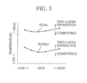
- a combination of R1234yf and PAG shows a low two-layer separation temperature, or temperature at which the refrigerant and the lubricant separates from each other, compared with the conventional combination of R134a and PAG.
- R1234yf and PAG are used in combination under the conventional operating conditions, it follows that the temperature of the working fluid in the condenser is higher than the two-layer separation temperature so that the refrigerant and the lubricant separate from each other in the condenser.
- the lubricant when R1234yf and PAG are used in combination, the lubricant accumulates in the condenser, so that a reduced amount of the lubricant returns to the compressor, resulting in inadequate lubrication in the compressor.
- the lubricant accumulating in the condenser hinders heat transfer in the condenser, resulting in a decrease in COP (coefficient of performance).
- PAG is however not always incompatible with R1234yf; PAG separates from R1234yf solely in the condenser. Given this, in order to prevent the lubricant from accumulating in the condenser, it is more direct and effective to prevent separation of the refrigerant and the lubricant in the condenser than to return the lubricant separated from the refrigerant.
- An object of the present invention is to provide a refrigeration cycle system which ensures adequate lubrication in the compressor and operates at a satisfactory COP, despite the use of a working fluid containing a refrigerant and a lubricant that separate from each other in the condenser, and an automotive air-conditioning system including the refrigeration cycle system.
- the present invention provides, as one embodiment, a refrigeration cycle system comprising a compressor, a condenser, an expansion valve and an evaporator disposed in a circulation path along which a working fluid containing a refrigerant and a lubricant that separate from each other at temperatures higher than a two-layer separation temperature flows, serially in a specified flow direction of the working fluid, and a lubricant return means for preventing the lubricant from accumulating in the condenser, wherein the lubricant return means reduces pressure of the refrigerant in the condenser to a saturation pressure of the refrigerant for said two-layer separation temperature or below, when the working fluid is made to flow along the circulation path in said specified flow direction and temperature around the condenser is lower than said two-layer separation temperature (claim 1).
- the lubricant return means includes a displacement regulation means for regulating displacement of the compressor to reduce the pressure of the refrigerant in the condenser by regulating the displacement of the compressor by using the displacement regulation means (claim 2).
- the lubricant return means further includes a flow reversing means for causing the working fluid to flow along the circulation path in a direction opposite to said specified flow direction (claim 3).
- the flow reversing means includes a four-way switch valve disposed in the circulation path and changed between a position to connect a discharge port and a suction of the compressor to an inlet of the condenser and an outlet of the evaporator, respectively, and a position to connect the discharge port and the suction of the compressor to the outlet of the evaporator and the inlet of the condenser, respectively (claim 4).
- the refrigerant and the lubricant contained in the working fluid are R1234yf and polyalkylene glycol, respectively (claim 5).
- the present invention also provides, as an embodiment, an automotive air-conditioning system including a refrigeration cycle system as described above.
- the lubricant return means reduces the pressure of the refrigerant in the condenser to the saturation pressure of the refrigerant for the two-layer separation temperature or below. This not only prevents the refrigerant and the lubricant from separating from each other in the condenser, but also causes the lubricant having accumulated in the condenser to mix with the refrigerant, and thus, ensures that the lubricant returns to the compressor with the refrigerant. As a result, adequate lubrication is maintained in the compressor and a decrease in COP (coefficient of performance) is prevented.
- the pressure of the refrigerant in the condenser is reliably reduced to the saturation pressure of the refrigerant for the two-layer separation temperature or below by regulating the displacement of the compressor.
- the flow reversing means can cause the working fluid at relatively low temperature to pass through the condenser, thereby causing the lubricant having accumulated in the condenser to mix with the refrigerant and return to the compressor.
- the lubricant having accumulated in the condenser is returned to the compressor, so that adequate lubrication is ensured in the compressor.
- the use of the four-way switch valve enables reliable return of the lubricant to the compressor with a simple structure.
- the refrigeration cycle system recited in claim 5, which uses low-GWP R1234yf as a refrigerant contained in the working fluid, is global environment-friendly.
- the working fluid also contains polyalkylene glycol as a lubricant, which ensures adequate lubrication in the compressor.
- the lubricant return means ensures that the lubricant having accumulated in the condenser is returned to the compressor, even in an environment in which the temperature of the working fluid exceeds the two-layer separation temperature in the condenser, and thus, the lubricant accumulates in the condenser.
- This automotive air-conditioning system is therefore useful in every region of the world.
- FIG. 1 schematically shows an automotive air-conditioning system according to a first embodiment.
- the automotive air conditioning system can cool a cabin 10 according to a temperature setting set as desired.
- the automotive air-conditioning system includes a refrigeration cycle system 12 for performing a refrigeration cycle.
- the refrigeration cycle system 12 has a circulation path 14 along which a working fluid is forced to circulate.
- the working fluid contains a refrigerant and a refrigerator oil (lubricant), and the refrigerant and the refrigerator oil separate from each other at temperatures higher than a two-layer separation temperature.
- the working fluid contains a refrigerant R1234yf and a lubricant PAG (polyalkylene glycol).
- the circulation path 14 runs from an engine room 16 to an instrument space 18 through a partition 17.
- the instrument space 18 is defined by an instrument panel 20 in front of the cabin 10.
- a compressor 22, a condenser and an expansion valve 25 are disposed in the circulation path 14, in its section inside the engine room 16, serially in a direction in which the working fluid normally flows (normal direction).
- An evaporator is disposed in the circulation path 14, in its section inside the instrument space 18.
- the compressor 22 is mechanically connected to an engine 29 by means of a belt and pulley system, for example, and driven by power from the engine 29.
- the compressor 22 is a variable displacement compressor and includes a displacement control valve.
- the displacement control valve includes a solenoid 30 electrically connected to a control device 32.
- the control device 32 regulates the displacement, or volume discharged by the compressor 22 per rotation, by regulating current supplied to the solenoid 30.
- the control device 32 may be composed of electric circuits, and for example, an ECU (electric control unit).
- the displacement may be regulated, for example by Ps control, i.e., controlling the pressure at which the working fluid is sucked into the compressor 22 (suction pressure), or differential pressure control, i.e., controlling the difference (Pd-Ps differential pressure) between the pressure at which the working fluid is discharged from the compressor 22 (discharge pressure) and the suction pressure.
- Ps control i.e., controlling the pressure at which the working fluid is sucked into the compressor 22 (suction pressure)
- differential pressure control i.e., controlling the difference (Pd-Ps differential pressure) between the pressure at which the working fluid is discharged from the compressor 22 (discharge pressure) and the suction pressure.
- a condenser fan 33 Near the condenser 24 is provided a condenser fan 33.
- the working fluid passing through the condenser 24 in the normal direction is cooled by airflow from before the vehicle, caused by the vehicle travelling, and/or airflow from the condenser fan 33.
- the expansion valve 26 is an electronic expansion valve.
- the control device 32 regulates the operating position of the expansion valve 26.
- the expansion valve 26 causes the working fluid flowing in the normal direction to expand.
- the evaporator 28 is disposed inside an air-conditioning unit housing 34. Also a blower fan 36 and a heater core (not shown) are disposed inside the air-conditioning unit housing 34. An inside/outside air switch damper 38 is arranged at an inlet of the air-conditioning unit housing 34, and a vent switch damper (not shown) is arranged at an outlet of the air-conditioning unit housing 34.
- the working fluid passing through the evaporator 28 in the normal direction evaporates by taking heat from air from the blower fan 36, so that the air from the blower fan 36 is cooled, or becomes cold air and flows into the cabin 10 to cool the cabin 10.
- the refrigeration cycle system 12 has a plurality of sensors providing various information.
- One of those sensors is a pressure sensor 40 for detecting pressure of the refrigerant in the condenser 24 (high-pressure).
- the pressure sensor 40 may be disposed in the circulation path 14, at any location between the compressor 22 and the inlet of the expansion valve 26. Here, it is disposed immediately downstream of the condenser 24 in consideration of durability.
- the high-pressure detected by the pressure sensor 40 is fed to the control device 32.
- the sensors provided in the refrigeration cycle system 12 also include an outside air temperature sensor 42 for detecting outside air temperature, or temperature around the condenser 24. Also the outside air temperature detected by the outside air temperature sensor 42 is fed to the control device 32.
- the control device 32 holds, on its database, data concerning relation between the outside air temperature and the refrigerant saturation pressure, so that the control device 32 can retrieve a refrigerant saturation pressure corresponding to an outside air temperature detected.
- the sensors provided in the refrigeration cycle system 12 also include an evaporator temperature sensor 44 for detecting temperature of air cooled in the evaporator 28 (evaporator temperature).
- the evaporator temperature detected by the evaporator temperature sensor 44 is fed to the control device 32 and used in determining a desired value of the suction pressure or of the Pd-Ps differential pressure, for example.
- a four-way switch valve 46 is disposed in the circulation path 14. As shown in FIG. 2 on an enlarged scale, the four-way switch valve 46 is changed between two positions to connect a discharge port and a suction port of the compressor 22 to an inlet of the condenser 24 and an outlet of the evaporator 28 in two alternative ways.
- the four-way switch valve 46 connects the discharge port and the suction port of the compressor 22 to the inlet of the condenser 24 and the outlet of the evaporator 28, respectively.
- the four-way switch valve 46 connects the discharge port and the suction port of the compressor 22 to the outlet of the evaporator 28 and the inlet of the condenser 24, respectively.
- the control device 32 controls the four-way switch valve 46 to take the normal position or the reverse position. Next, how to use the above-described automotive air-conditioning system, or in other words, control performed by the control device 32 will be explained.
- the control device 32 can perform control in a mode selected from a normal operation mode and a first lubricant return mode and possibly also a second lubricant return mode, depending on the varying situation.
- the second lubricant return mode is provided as necessary.
- the control device 32 makes the automotive air-conditioning system operate so that the temperature in the cabin 10 will approach a temperature setting set by a passenger in the vehicle, for example.
- the displacement of the compressor 22 and the operating position of the expansion valve 26 are controlled so that the temperature of the air after passing across the evaporator 28 will approach a desired value.
- the control device 32 makes the automotive air-conditioning system operate so that accumulation of the lubricant in the condenser 24 will be prevented.
- the accumulation of the lubricant in the condenser 24 not only means that the lubricant accumulates in the condenser 24 but also that the lubricant adheres to the inner surface of the condenser 24 to some extent.
- the first and second lubricant return modes are provided in consideration of the fact that R1234yf and PAG experience two-layer separation at low temperature compared with, for example R134a and PAG, as shown in FIG. 3 .
- the horizontal axis indicates the ratio of the lubricant to the circulating working fluid.
- FIG. 4 shows a kinematic viscosity versus temperature chart, where how the kinematic viscosity of the working fluid containing a refrigerant R1234yf and a lubricant PAG at different lubricant concentrations 0, 10, 20 and 30 % varies with temperature is plotted (chain lines).
- isobaric lines are plotted (broken lines), the refrigeration cycle in the normal operation mode is indicated by A(compressor inlet port)-B(compressor outlet port)-C(expansion valve inlet)-D(expansion valve outlet) line, the refrigeration cycle in the first lubricant return mode is indicated by O(compressor inlet port)-P(compressor outlet port)-Q(expansion valve inlet)-R(expansion valve outlet) line, and a region in which R1234yf and PAG experience two-layer separation (incompatibility region) is indicated by hatching.
- FIG. 4 shows that the refrigeration cycle in the normal operation mode A-B-C-D, specifically process B-C traverses the incompatibility region, which means the lubricant separates from the refrigerant in the condenser 24.
- the refrigeration cycle in the first lubricant return mode O-P-Q-R does not traverse the incompatibility region. This is because the first lubricant return mode is provided to return the lubricant having accumulated in the condenser 24 to the compressor 22, when the two-layer separation temperature for the refrigerant and lubricant is lower than the temperature around the condenser 24 (outside air temperature).
- the automotive air-conditioning system is made to operate to reduce the pressure of the refrigerant in the condenser 24 to a saturation pressure of the refrigerant for the outside temperature or below.
- the control device 32 reduces the pressure of the refrigerant in the condenser 24 to the saturation pressure of the refrigerant for the outside temperature or below by reducing the displacement of the compressor 22.
- the control in the first lubrication return mode causes the lubricant having accumulated in the condenser 24 to mix with the refrigerant, and thus, return to the compressor 22 by flowing with the refrigerant along the circulation path 14 in the normal direction.
- the pressure of the refrigerant in the condenser 24 may be reduced to the saturation pressure of the refrigerant for the outside temperature or below by taking one or more measures selected from increase of airflow from the condenser fan 33, reduction of airflow from the blower fan 36 and change of the inside/outside air switch damper 38 into an inside air circulation position, in addition to reducing the displacement.
- the second lubricant return mode is provided to return the lubricant having accumulated in the condenser 24 to the compressor 22, when the two-layer separation temperature for the refrigerant and lubricant is higher than or equal to the temperature around the condenser 24 (outside air temperature).
- the second lubricant return mode is therefore not necessarily required in cold weather regions.
- the control device 32 changes the four-way switch valve 46 from the normal position to the reverse position.
- the refrigerant discharged from the compressor 22 flows along the circulation path 14 in the reverse direction, namely flows through the evaporator 28, the expansion valve 26 and the condenser 24 serially, and is sucked into the compressor 22.
- the working fluid at low temperature passing through the condenser 24 mixes with the lubricant having accumulated in the condenser 24, and returns to the compressor 22.
- FIG. 5 is a kinematic viscosity versus temperature chart for an comparative example, where how the kinematic viscosity of the working fluid containing a refrigerant R134a and a lubricant PAG at different lubricant concentrations 0, 10, 20 and 30 % varies with temperature is plotted (chain lines) with isobaric lines (broken line), the refrigeration cycle in the normal operation mode is indicated by X(compressor inlet port)-Y(compressor outlet port)-V(expansion valve inlet)-W(expansion valve outlet) line, and an incompatibility region for R134a and PAG is indicated (by hatching).
- FIG. 5 shows that the refrigeration cycle X-Y-V-W does not traverses the incompatibility region, which means the R134a and PAG does not experience two-layer separation. If the refrigeration cycle in the normal operation mode does not traverses the incompatibility region like this, the first and second lubrication return modes are not required.
- control in the normal operation mode allows the cabin 10 to be cooled or dehumidified according to a passenger's instruction.
- the refrigeration cycle A-B-C-D traverses the two-layer separation region, and thus, the lubricant adheres to the inner surface of the condenser 24 and of a section of the piping near the condenser 24, and thus, accumulates.
- control device 32 When the lubricant accumulates in the condenser 24 to a certain extent, the control device 32 performs control in the first or second lubricant return mode to return the lubricant having accumulated to the compressor 22 to the compressor 22.
- control in the first lubricant return mode is performed to reduce the pressure of the refrigerant in the condenser 24 to the saturation pressure of the refrigerant for the two-layer separation temperature or below. This allows the lubricant having accumulated in the condenser 24 to mix with the refrigerant and return to the compressor 22 with the refrigerant, and thus, keeps adequate lubrication in the compressor 22 and prevents reduction in COP.
- the pressure of the refrigerant in the condenser 24 is reliably reduced to the saturation pressure of the refrigerant for the two-layer separation temperature or below by regulating the displacement of the compressor 22.
- control in the second lubricant return mode is performed to return the lubricant having accumulated in the condenser 24 to the compressor 22 to ensure adequate lubrication in the compressor 22.
- the use of the four-way switch valve 46 enables reliable return of the lubricant to the compressor 22 with a simple structure.
- the described refrigerant cycle circuit 12 which uses a working fluid containing low-GWP R1234yf as a refrigerant, is global environment-friendly.
- the working fluid also contains polyalkylene glycol as a lubricant, which ensures adequate lubrication in the compressor 22.
- the temperature of the refrigerant in the condenser 22 is kept lower than or equal to the two-layer separation temperature, even in an environment in which the control in the normal operation mode results in its exceeding the two-layer separation temperature.
- This automotive air-conditioning system is therefore useful in every region of the world.
- the working fluid contains a refrigerant R1234yf and a lubricant PAG.
- the refrigerant and the lubricant are however not restricted to these.
- the refrigeration cycle according to the present invention is applicable to working fluids experiencing separation of a refrigerant and a lubricant in the condenser 24.
- control device 32 performs control in the first or second lubricant return mode when the lubricant has accumulated in the condenser 24 to a certain extent.
- the control device may however perform control in the first or second lubricant return mode, on a regular or irregular basis.
- control device performs control in the first or second lubricant return mode after a long period of low-flow rate circulation of the working fluid, as observed in long engine idling in the vehicle, for example.
- control device performs control in the first or second lubricant return mode when the heat-transfer effectiveness in the condenser 24 has reduced to a certain level or when the amount of the lubricant inside the compressor 22 has reduced to a certain level.
- a four-way switch valve 46 is provided as a means for making the working fluid flow along the circulation path 14 in the reverse direction.
- the reversing means may however be a plurality of solenoid valves, for example.
- the expansion valve 26 may be a temperature-sensitive expansion valve or the like if control in the second lubricant return mode is not required.
- the compressor 22 may be any type of compressor; it may be a swash-plate or wobble-plate reciprocating compressor, a scroll compressor or a vane compressor, for example.
- the refrigeration cycle system according to the present invention is applicable to refrigerator-freezers, room air-conditioners, etc.
- the present invention is applicable to a refrigeration cycle system using a working fluid containing a lubricant and a refrigeration that separate from each other in a condenser and an automotive air-conditioning system including such refrigeration cycle system, in order to ensure adequate lubrication in the compressor and satisfactory COP.
Landscapes
- Engineering & Computer Science (AREA)
- Physics & Mathematics (AREA)
- Mechanical Engineering (AREA)
- Thermal Sciences (AREA)
- General Engineering & Computer Science (AREA)
- Air-Conditioning For Vehicles (AREA)
- Compression-Type Refrigeration Machines With Reversible Cycles (AREA)
Abstract
Description
- This invention relates to a refrigeration cycle system and an automotive air-conditioning system including the refrigeration cycle system.
- A system for performing a refrigeration cycle (refrigeration cycle system) has a circulation path along which a working fluid containing a refrigerant and a lubricant is forced to circulate.
- There are a variety of refrigerants and a variety of lubricants (refrigerator oils), and some combinations of a refrigerant and a lubricant show low compatibility. Patent document 1 points out that use of low-compatible refrigerant and refrigerator oil in combination may lead to accumulation of the refrigerator oil in piping, particularly in a heat pump air-conditioner designed to also perform the refrigeration cycle with the flow of the refrigerant reversed, and thus, oil deficiency in the compressor. Patent document 1 also points out that the refrigerator oil does not satisfactorily return to the compressor, particularly at low revolving speeds of the compressor.
- In view of this, patent document 1 discloses control of compressor revolving speed or expansion valve position to make the refrigerant flow upward in an ascending section of piping at a velocity higher than the flow velocity that causes the oil adhering to the inner surface of the piping to ascend (zero penetration velocity).
- Patent document 1: Japanese Patent Application Laid-open No.
2001-272117 - To protect the global environment, research and development of new refrigerants to substitute for R134a has been being advanced. An example of such new refrigerant is R1234yf (Tetrafluoropropene: F3C-CF=CH2). R1234yf has a GWP (global warming potential) of 4, far lower than R134a's GWP of 1300.
- However, a combination of R1234yf and PAG (polyalkylene glycol) shows a low two-layer separation temperature, or temperature at which the refrigerant and the lubricant separates from each other, compared with the conventional combination of R134a and PAG. Thus, if R1234yf and PAG are used in combination under the conventional operating conditions, it follows that the temperature of the working fluid in the condenser is higher than the two-layer separation temperature so that the refrigerant and the lubricant separate from each other in the condenser.
- Thus, when R1234yf and PAG are used in combination, the lubricant accumulates in the condenser, so that a reduced amount of the lubricant returns to the compressor, resulting in inadequate lubrication in the compressor. In addition, the lubricant accumulating in the condenser hinders heat transfer in the condenser, resulting in a decrease in COP (coefficient of performance).
- It is thought that if the refrigerant is made to flow at a velocity higher than the zero penetration velocity by using the technology disclosed in patent document 1, the separated lubricant can be returned to the compressor to some extent.
- PAG is however not always incompatible with R1234yf; PAG separates from R1234yf solely in the condenser. Given this, in order to prevent the lubricant from accumulating in the condenser, it is more direct and effective to prevent separation of the refrigerant and the lubricant in the condenser than to return the lubricant separated from the refrigerant.
- Further, under some operating conditions of the refrigeration cycle, keeping the flow velocity of the refrigerant higher than or equal to the zero penetration velocity results in keeping the temperature of the working fluid in the condenser higher than the two-layer separation temperature. It is therefore likely to cause the separation of the lubricant in the condenser.
- The present invention has been made in consideration of the above problems. An object of the present invention is to provide a refrigeration cycle system which ensures adequate lubrication in the compressor and operates at a satisfactory COP, despite the use of a working fluid containing a refrigerant and a lubricant that separate from each other in the condenser, and an automotive air-conditioning system including the refrigeration cycle system.
- In order to achieve the above object, the present invention provides, as one embodiment, a refrigeration cycle system comprising a compressor, a condenser, an expansion valve and an evaporator disposed in a circulation path along which a working fluid containing a refrigerant and a lubricant that separate from each other at temperatures higher than a two-layer separation temperature flows, serially in a specified flow direction of the working fluid, and a lubricant return means for preventing the lubricant from accumulating in the condenser, wherein the lubricant return means reduces pressure of the refrigerant in the condenser to a saturation pressure of the refrigerant for said two-layer separation temperature or below, when the working fluid is made to flow along the circulation path in said specified flow direction and temperature around the condenser is lower than said two-layer separation temperature (claim 1).
- Desirably, the lubricant return means includes a displacement regulation means for regulating displacement of the compressor to reduce the pressure of the refrigerant in the condenser by regulating the displacement of the compressor by using the displacement regulation means (claim 2).
- Desirably, the lubricant return means further includes a flow reversing means for causing the working fluid to flow along the circulation path in a direction opposite to said specified flow direction (claim 3).
- Desirably, the flow reversing means includes a four-way switch valve disposed in the circulation path and changed between a position to connect a discharge port and a suction of the compressor to an inlet of the condenser and an outlet of the evaporator, respectively, and a position to connect the discharge port and the suction of the compressor to the outlet of the evaporator and the inlet of the condenser, respectively (claim 4).
- Desirably, the refrigerant and the lubricant contained in the working fluid are R1234yf and polyalkylene glycol, respectively (claim 5).
- The present invention also provides, as an embodiment, an automotive air-conditioning system including a refrigeration cycle system as described above.
- In the refrigeration cycle system according to the present invention recited in claim 1, when the temperature around the condenser is lower than the two-layer separation temperature, the lubricant return means reduces the pressure of the refrigerant in the condenser to the saturation pressure of the refrigerant for the two-layer separation temperature or below. This not only prevents the refrigerant and the lubricant from separating from each other in the condenser, but also causes the lubricant having accumulated in the condenser to mix with the refrigerant, and thus, ensures that the lubricant returns to the compressor with the refrigerant. As a result, adequate lubrication is maintained in the compressor and a decrease in COP (coefficient of performance) is prevented.
- In the refrigeration cycle system recited in claim 2, the pressure of the refrigerant in the condenser is reliably reduced to the saturation pressure of the refrigerant for the two-layer separation temperature or below by regulating the displacement of the compressor.
- In the refrigeration cycle system recited in claim 3, the flow reversing means can cause the working fluid at relatively low temperature to pass through the condenser, thereby causing the lubricant having accumulated in the condenser to mix with the refrigerant and return to the compressor. Thus, even when the temperature around the condenser is higher than the two-layer separation temperature, the lubricant having accumulated in the condenser is returned to the compressor, so that adequate lubrication is ensured in the compressor.
- In the refrigeration cycle system recited in claim 4, the use of the four-way switch valve enables reliable return of the lubricant to the compressor with a simple structure.
- The refrigeration cycle system recited in claim 5, which uses low-GWP R1234yf as a refrigerant contained in the working fluid, is global environment-friendly. The working fluid also contains polyalkylene glycol as a lubricant, which ensures adequate lubrication in the compressor.
- In the automotive air-conditioning system recited in claim 6, the lubricant return means ensures that the lubricant having accumulated in the condenser is returned to the compressor, even in an environment in which the temperature of the working fluid exceeds the two-layer separation temperature in the condenser, and thus, the lubricant accumulates in the condenser. This automotive air-conditioning system is therefore useful in every region of the world.
-
-
FIG. 1 is a diagram schematically showing a configuration of an automotive air-conditioning system according to a first embodiment, -
FIG. 2 is a diagram showing a part of the automotive air-conditioning system near a four-way switch valve, inclusive of the four-way switch valve, on an enlarged scale, -
FIG. 3 is a graph representing relation between two-layer separation temperature and oil circulation ratio for a combination of R1234yf and PAG and a combination of R134a and PAG, -
FIG. 4 is a graph showing relation between kinematic viscosity and temperature for a combination of R1234yf and PAG, together with isothermal lines, an incompatibility region and refrigeration cycles, and -
FIG. 5 is a graph representing relation between kinematic viscosity and temperature for a combination of R134a and PAG, together with isothermal lines, an incompatibility region and a refrigeration cycle. -
- 12
- Refrigeration cycle system
- 14
- Circulation path
- 22
- Compressor
- 24
- Condenser
- 26
- Expansion valve
- 28
- Evaporator
-
FIG. 1 schematically shows an automotive air-conditioning system according to a first embodiment. The automotive air conditioning system can cool acabin 10 according to a temperature setting set as desired. The automotive air-conditioning system includes arefrigeration cycle system 12 for performing a refrigeration cycle. Therefrigeration cycle system 12 has acirculation path 14 along which a working fluid is forced to circulate. - The working fluid contains a refrigerant and a refrigerator oil (lubricant), and the refrigerant and the refrigerator oil separate from each other at temperatures higher than a two-layer separation temperature. Preferably, the working fluid contains a refrigerant R1234yf and a lubricant PAG (polyalkylene glycol).
- The
circulation path 14 runs from anengine room 16 to aninstrument space 18 through apartition 17. Theinstrument space 18 is defined by aninstrument panel 20 in front of thecabin 10. Acompressor 22, a condenser and an expansion valve 25 are disposed in thecirculation path 14, in its section inside theengine room 16, serially in a direction in which the working fluid normally flows (normal direction). An evaporator is disposed in thecirculation path 14, in its section inside theinstrument space 18. - The
compressor 22 is mechanically connected to anengine 29 by means of a belt and pulley system, for example, and driven by power from theengine 29. Preferably, thecompressor 22 is a variable displacement compressor and includes a displacement control valve. - The displacement control valve includes a
solenoid 30 electrically connected to acontrol device 32. Thecontrol device 32 regulates the displacement, or volume discharged by thecompressor 22 per rotation, by regulating current supplied to thesolenoid 30. Thecontrol device 32 may be composed of electric circuits, and for example, an ECU (electric control unit). - The displacement may be regulated, for example by Ps control, i.e., controlling the pressure at which the working fluid is sucked into the compressor 22 (suction pressure), or differential pressure control, i.e., controlling the difference (Pd-Ps differential pressure) between the pressure at which the working fluid is discharged from the compressor 22 (discharge pressure) and the suction pressure.
- Near the
condenser 24 is provided acondenser fan 33. The working fluid passing through thecondenser 24 in the normal direction is cooled by airflow from before the vehicle, caused by the vehicle travelling, and/or airflow from thecondenser fan 33. - Preferably, the
expansion valve 26 is an electronic expansion valve. Thecontrol device 32 regulates the operating position of theexpansion valve 26. Theexpansion valve 26 causes the working fluid flowing in the normal direction to expand. - The
evaporator 28 is disposed inside an air-conditioning unit housing 34. Also ablower fan 36 and a heater core (not shown) are disposed inside the air-conditioning unit housing 34. An inside/outsideair switch damper 38 is arranged at an inlet of the air-conditioning unit housing 34, and a vent switch damper (not shown) is arranged at an outlet of the air-conditioning unit housing 34. - The working fluid passing through the
evaporator 28 in the normal direction evaporates by taking heat from air from theblower fan 36, so that the air from theblower fan 36 is cooled, or becomes cold air and flows into thecabin 10 to cool thecabin 10. - The
refrigeration cycle system 12 has a plurality of sensors providing various information. One of those sensors is apressure sensor 40 for detecting pressure of the refrigerant in the condenser 24 (high-pressure). Thepressure sensor 40 may be disposed in thecirculation path 14, at any location between thecompressor 22 and the inlet of theexpansion valve 26. Here, it is disposed immediately downstream of thecondenser 24 in consideration of durability. The high-pressure detected by thepressure sensor 40 is fed to thecontrol device 32. - The sensors provided in the
refrigeration cycle system 12 also include an outsideair temperature sensor 42 for detecting outside air temperature, or temperature around thecondenser 24. Also the outside air temperature detected by the outsideair temperature sensor 42 is fed to thecontrol device 32. Thecontrol device 32 holds, on its database, data concerning relation between the outside air temperature and the refrigerant saturation pressure, so that thecontrol device 32 can retrieve a refrigerant saturation pressure corresponding to an outside air temperature detected. - The sensors provided in the
refrigeration cycle system 12 also include anevaporator temperature sensor 44 for detecting temperature of air cooled in the evaporator 28 (evaporator temperature). The evaporator temperature detected by theevaporator temperature sensor 44 is fed to thecontrol device 32 and used in determining a desired value of the suction pressure or of the Pd-Ps differential pressure, for example. - Preferably, a four-
way switch valve 46 is disposed in thecirculation path 14. As shown inFIG. 2 on an enlarged scale, the four-way switch valve 46 is changed between two positions to connect a discharge port and a suction port of thecompressor 22 to an inlet of thecondenser 24 and an outlet of theevaporator 28 in two alternative ways. - Specifically, in a normal position, the four-
way switch valve 46 connects the discharge port and the suction port of thecompressor 22 to the inlet of thecondenser 24 and the outlet of theevaporator 28, respectively. In a reverse position shown inFIG. 2 , the four-way switch valve 46 connects the discharge port and the suction port of thecompressor 22 to the outlet of theevaporator 28 and the inlet of thecondenser 24, respectively. - The
control device 32 controls the four-way switch valve 46 to take the normal position or the reverse position. Next, how to use the above-described automotive air-conditioning system, or in other words, control performed by thecontrol device 32 will be explained. - The
control device 32 can perform control in a mode selected from a normal operation mode and a first lubricant return mode and possibly also a second lubricant return mode, depending on the varying situation. The second lubricant return mode is provided as necessary. - In the normal operation mode, the
control device 32 makes the automotive air-conditioning system operate so that the temperature in thecabin 10 will approach a temperature setting set by a passenger in the vehicle, for example. In this case, the displacement of thecompressor 22 and the operating position of theexpansion valve 26 are controlled so that the temperature of the air after passing across theevaporator 28 will approach a desired value. - In the first and second lubricant return modes, the
control device 32 makes the automotive air-conditioning system operate so that accumulation of the lubricant in thecondenser 24 will be prevented. Here, the accumulation of the lubricant in thecondenser 24 not only means that the lubricant accumulates in thecondenser 24 but also that the lubricant adheres to the inner surface of thecondenser 24 to some extent. - The first and second lubricant return modes are provided in consideration of the fact that R1234yf and PAG experience two-layer separation at low temperature compared with, for example R134a and PAG, as shown in
FIG. 3 . InFIG. 3 , the horizontal axis indicates the ratio of the lubricant to the circulating working fluid. -
FIG. 4 shows a kinematic viscosity versus temperature chart, where how the kinematic viscosity of the working fluid containing a refrigerant R1234yf and a lubricant PAG atdifferent lubricant concentrations FIG. 4 , also isobaric lines are plotted (broken lines), the refrigeration cycle in the normal operation mode is indicated by A(compressor inlet port)-B(compressor outlet port)-C(expansion valve inlet)-D(expansion valve outlet) line, the refrigeration cycle in the first lubricant return mode is indicated by O(compressor inlet port)-P(compressor outlet port)-Q(expansion valve inlet)-R(expansion valve outlet) line, and a region in which R1234yf and PAG experience two-layer separation (incompatibility region) is indicated by hatching. -
FIG. 4 shows that the refrigeration cycle in the normal operation mode A-B-C-D, specifically process B-C traverses the incompatibility region, which means the lubricant separates from the refrigerant in thecondenser 24. - By contrast, the refrigeration cycle in the first lubricant return mode O-P-Q-R does not traverse the incompatibility region. This is because the first lubricant return mode is provided to return the lubricant having accumulated in the
condenser 24 to thecompressor 22, when the two-layer separation temperature for the refrigerant and lubricant is lower than the temperature around the condenser 24 (outside air temperature). - To achieve this, in the first lubricant return mode, the automotive air-conditioning system is made to operate to reduce the pressure of the refrigerant in the
condenser 24 to a saturation pressure of the refrigerant for the outside temperature or below. Preferably, thecontrol device 32 reduces the pressure of the refrigerant in thecondenser 24 to the saturation pressure of the refrigerant for the outside temperature or below by reducing the displacement of thecompressor 22. - The control in the first lubrication return mode causes the lubricant having accumulated in the
condenser 24 to mix with the refrigerant, and thus, return to thecompressor 22 by flowing with the refrigerant along thecirculation path 14 in the normal direction. - The pressure of the refrigerant in the condenser 24 (high-pressure) may be reduced to the saturation pressure of the refrigerant for the outside temperature or below by taking one or more measures selected from increase of airflow from the
condenser fan 33, reduction of airflow from theblower fan 36 and change of the inside/outsideair switch damper 38 into an inside air circulation position, in addition to reducing the displacement. - The second lubricant return mode is provided to return the lubricant having accumulated in the
condenser 24 to thecompressor 22, when the two-layer separation temperature for the refrigerant and lubricant is higher than or equal to the temperature around the condenser 24 (outside air temperature). The second lubricant return mode is therefore not necessarily required in cold weather regions. - To achieve this, in the second lubricant return mode, the
control device 32 changes the four-way switch valve 46 from the normal position to the reverse position. As a result, the refrigerant discharged from thecompressor 22 flows along thecirculation path 14 in the reverse direction, namely flows through theevaporator 28, theexpansion valve 26 and thecondenser 24 serially, and is sucked into thecompressor 22. - In the second lubricant return mode, the working fluid at low temperature passing through the
condenser 24 mixes with the lubricant having accumulated in thecondenser 24, and returns to thecompressor 22. -
FIG. 5 is a kinematic viscosity versus temperature chart for an comparative example, where how the kinematic viscosity of the working fluid containing a refrigerant R134a and a lubricant PAG atdifferent lubricant concentrations -
FIG. 5 shows that the refrigeration cycle X-Y-V-W does not traverses the incompatibility region, which means the R134a and PAG does not experience two-layer separation. If the refrigeration cycle in the normal operation mode does not traverses the incompatibility region like this, the first and second lubrication return modes are not required. - In the above-described embodiment of the
refrigeration cycle system 12 applied to the automotive air-conditioning system, control in the normal operation mode allows thecabin 10 to be cooled or dehumidified according to a passenger's instruction. - In the normal operation mode, the refrigeration cycle A-B-C-D traverses the two-layer separation region, and thus, the lubricant adheres to the inner surface of the
condenser 24 and of a section of the piping near thecondenser 24, and thus, accumulates. - When the lubricant accumulates in the
condenser 24 to a certain extent, thecontrol device 32 performs control in the first or second lubricant return mode to return the lubricant having accumulated to thecompressor 22 to thecompressor 22. - Specifically, when the temperature around the
condenser 24 is lower than the two-layer separation temperature, control in the first lubricant return mode is performed to reduce the pressure of the refrigerant in thecondenser 24 to the saturation pressure of the refrigerant for the two-layer separation temperature or below. This allows the lubricant having accumulated in thecondenser 24 to mix with the refrigerant and return to thecompressor 22 with the refrigerant, and thus, keeps adequate lubrication in thecompressor 22 and prevents reduction in COP. - In the described
refrigeration cycle circuit 12, the pressure of the refrigerant in thecondenser 24 is reliably reduced to the saturation pressure of the refrigerant for the two-layer separation temperature or below by regulating the displacement of thecompressor 22. - In the described
refrigeration cycle circuit 12, when the temperature around thecondenser 24 is higher than or equal to the two-layer separation temperature, control in the second lubricant return mode is performed to return the lubricant having accumulated in thecondenser 24 to thecompressor 22 to ensure adequate lubrication in thecompressor 22. - In the described
refrigeration cycle circuit 12, the use of the four-way switch valve 46 enables reliable return of the lubricant to thecompressor 22 with a simple structure. - Further, the described
refrigerant cycle circuit 12, which uses a working fluid containing low-GWP R1234yf as a refrigerant, is global environment-friendly. The working fluid also contains polyalkylene glycol as a lubricant, which ensures adequate lubrication in thecompressor 22. - In the above-described automotive air-conditioning system, the temperature of the refrigerant in the
condenser 22 is kept lower than or equal to the two-layer separation temperature, even in an environment in which the control in the normal operation mode results in its exceeding the two-layer separation temperature. This automotive air-conditioning system is therefore useful in every region of the world. - The present invention is not restricted to the above-described embodiment but can be modified in various ways.
- For example, in the described embodiment, the working fluid contains a refrigerant R1234yf and a lubricant PAG. The refrigerant and the lubricant are however not restricted to these. The refrigeration cycle according to the present invention is applicable to working fluids experiencing separation of a refrigerant and a lubricant in the
condenser 24. - In the described embodiment, the
control device 32 performs control in the first or second lubricant return mode when the lubricant has accumulated in thecondenser 24 to a certain extent. The control device may however perform control in the first or second lubricant return mode, on a regular or irregular basis. - Alternatively, it may be arranged such that the control device performs control in the first or second lubricant return mode after a long period of low-flow rate circulation of the working fluid, as observed in long engine idling in the vehicle, for example.
- Further, it may be arranged such that the control device performs control in the first or second lubricant return mode when the heat-transfer effectiveness in the
condenser 24 has reduced to a certain level or when the amount of the lubricant inside thecompressor 22 has reduced to a certain level. - In the described embodiment, a four-
way switch valve 46 is provided as a means for making the working fluid flow along thecirculation path 14 in the reverse direction. The reversing means may however be a plurality of solenoid valves, for example. - In the described embodiment, the
expansion valve 26 may be a temperature-sensitive expansion valve or the like if control in the second lubricant return mode is not required. - In the described embodiment, the
compressor 22 may be any type of compressor; it may be a swash-plate or wobble-plate reciprocating compressor, a scroll compressor or a vane compressor, for example. - Last, it goes without saying that the refrigeration cycle system according to the present invention is applicable to refrigerator-freezers, room air-conditioners, etc.
- The present invention is applicable to a refrigeration cycle system using a working fluid containing a lubricant and a refrigeration that separate from each other in a condenser and an automotive air-conditioning system including such refrigeration cycle system, in order to ensure adequate lubrication in the compressor and satisfactory COP.
Claims (6)
- A refrigeration cycle system comprising a compressor, a condenser, an expansion valve and an evaporator disposed in a circulation path along which a working fluid containing a refrigerant and a lubricant that separate from each other at temperatures higher than a two-layer separation temperature flows, serially in a specified flow direction of the working fluid, and a lubricant return means for preventing the lubricant from accumulating in the condenser, wherein
the lubricant return means reduces pressure of the refrigerant in the condenser to a saturation pressure of the refrigerant for said two-layer separation temperature or below, when the working fluid is made to flow along the circulation path in said specified flow direction and temperature around the condenser is lower than said two-layer separation temperature. - The refrigeration cycle system according to claim 1, wherein the lubricant return means includes a displacement regulation means for regulating displacement of the compressor to reduce the pressure of the refrigerant by regulating the displacement of the compressor by using the displacement regulation means.
- The refrigeration cycle system according to claim 1 or 2, wherein the lubricant return means further includes a flow reversing means for causing the working fluid to flow along the circulation path in a direction opposite to said specified flow direction.
- The refrigeration cycle system according to claim 3, wherein the flow reversing means includes a four-way switch valve disposed in the circulation path and changed between a position to connect a discharge port and a suction of the compressor to an inlet of the condenser and an outlet of the evaporator, respectively, and a position to connect the, discharge port and the suction of the compressor to the outlet of the evaporator and the inlet of the condenser, respectively.
- The refrigeration cycle system according to any one of claims 1 to 4, wherein the working fluid contains polyalkylene glycol as the lubricant and R1234yf as the refrigerant.
- An automotive air-conditioning system including a refrigeration cycle system according to any of claims 1 to 5.
Applications Claiming Priority (2)
| Application Number | Priority Date | Filing Date | Title |
|---|---|---|---|
| JP2008272955A JP5379445B2 (en) | 2008-10-23 | 2008-10-23 | Refrigeration cycle system and vehicle air conditioning system using the refrigeration cycle system |
| PCT/JP2009/068642 WO2010047421A1 (en) | 2008-10-23 | 2009-10-23 | Refrigeration cycle system and automotive air conditioning system using said refrigeration cycle system |
Publications (2)
| Publication Number | Publication Date |
|---|---|
| EP2336674A1 true EP2336674A1 (en) | 2011-06-22 |
| EP2336674A4 EP2336674A4 (en) | 2012-01-04 |
Family
ID=42119449
Family Applications (1)
| Application Number | Title | Priority Date | Filing Date |
|---|---|---|---|
| EP09822113A Withdrawn EP2336674A4 (en) | 2008-10-23 | 2009-10-23 | Refrigeration cycle system and automotive air conditioning system using said refrigeration cycle system |
Country Status (4)
| Country | Link |
|---|---|
| US (1) | US20110192187A1 (en) |
| EP (1) | EP2336674A4 (en) |
| JP (1) | JP5379445B2 (en) |
| WO (1) | WO2010047421A1 (en) |
Cited By (2)
| Publication number | Priority date | Publication date | Assignee | Title |
|---|---|---|---|---|
| EP2342302B1 (en) | 2008-11-03 | 2017-04-26 | Arkema France | Vehicle heating and/or air conditioning method |
| EP3752572B1 (en) | 2018-02-15 | 2024-05-22 | Arkema France | Method for heating and/or cooling a vehicle |
Families Citing this family (7)
| Publication number | Priority date | Publication date | Assignee | Title |
|---|---|---|---|---|
| JP2012047152A (en) * | 2010-08-30 | 2012-03-08 | Toyota Industries Corp | Rankine cycle apparatus |
| JP5721480B2 (en) * | 2011-03-10 | 2015-05-20 | 三菱電機株式会社 | Refrigeration cycle equipment |
| JP5482728B2 (en) | 2011-05-20 | 2014-05-07 | 株式会社デンソー | Refrigeration cycle equipment |
| US9328956B2 (en) * | 2012-12-18 | 2016-05-03 | General Electric Company | Refrigerator control system and method |
| WO2016125239A1 (en) * | 2015-02-02 | 2016-08-11 | 三菱電機株式会社 | Refrigeration/air-conditioning device |
| KR101673846B1 (en) * | 2016-04-11 | 2016-11-09 | 대성히트펌프 주식회사 | Method for controlling oil recovery in heatpump system, and heatpump system with oil recovery control fuction |
| CN112455288B (en) * | 2020-12-24 | 2022-03-22 | 浙江吉利控股集团有限公司 | A thermal management system for extended-range hybrid electric vehicles |
Family Cites Families (10)
| Publication number | Priority date | Publication date | Assignee | Title |
|---|---|---|---|---|
| JPH04110388A (en) * | 1990-08-31 | 1992-04-10 | Daikin Ind Ltd | heat transfer fluid |
| US5534176A (en) * | 1991-07-30 | 1996-07-09 | Alliedsignal Inc. | Refrigeration lubricants prepared by polymerizing alkene having a perfluoroalkyl group on one end thereof |
| JP2869904B2 (en) * | 1991-09-25 | 1999-03-10 | 株式会社ゼクセル | Refrigeration cycle control device |
| JPH10132406A (en) * | 1996-10-31 | 1998-05-22 | Daikin Ind Ltd | Refrigeration equipment |
| JPH1130445A (en) * | 1997-07-10 | 1999-02-02 | Denso Corp | Refrigeration cycle device |
| TW400377B (en) * | 1997-09-09 | 2000-08-01 | Hitachi Ltd | Refrigerating machine oil composition, and refrigeration and compressor using the refrigerating machine oil composition |
| JP2000346470A (en) * | 1999-06-03 | 2000-12-15 | Bosch Automotive Systems Corp | Air conditioner for vehicle |
| JP4078786B2 (en) | 2000-03-29 | 2008-04-23 | 三菱電機株式会社 | Refrigeration and air conditioning cycle equipment |
| JP4063023B2 (en) * | 2002-09-12 | 2008-03-19 | 株式会社デンソー | Vapor compression refrigerator |
| US20060243944A1 (en) * | 2005-03-04 | 2006-11-02 | Minor Barbara H | Compositions comprising a fluoroolefin |
-
2008
- 2008-10-23 JP JP2008272955A patent/JP5379445B2/en not_active Expired - Fee Related
-
2009
- 2009-10-23 US US13/125,386 patent/US20110192187A1/en not_active Abandoned
- 2009-10-23 EP EP09822113A patent/EP2336674A4/en not_active Withdrawn
- 2009-10-23 WO PCT/JP2009/068642 patent/WO2010047421A1/en not_active Ceased
Cited By (3)
| Publication number | Priority date | Publication date | Assignee | Title |
|---|---|---|---|---|
| EP2342302B1 (en) | 2008-11-03 | 2017-04-26 | Arkema France | Vehicle heating and/or air conditioning method |
| EP3205699A1 (en) * | 2008-11-03 | 2017-08-16 | Arkema France | Heating and/or air conditioning method for a vehicle |
| EP3752572B1 (en) | 2018-02-15 | 2024-05-22 | Arkema France | Method for heating and/or cooling a vehicle |
Also Published As
| Publication number | Publication date |
|---|---|
| JP5379445B2 (en) | 2013-12-25 |
| WO2010047421A1 (en) | 2010-04-29 |
| US20110192187A1 (en) | 2011-08-11 |
| JP2010101553A (en) | 2010-05-06 |
| EP2336674A4 (en) | 2012-01-04 |
Similar Documents
| Publication | Publication Date | Title |
|---|---|---|
| EP2336674A1 (en) | Refrigeration cycle system and automotive air conditioning system using said refrigeration cycle system | |
| US11479086B2 (en) | Multi-compressor climate system | |
| US6681582B2 (en) | Vapor compression type refrigeration apparatus including leak detection and method for detecting refrigerant leaks | |
| CN113776241B (en) | Oil distribution in multiple compressor system with variable speed | |
| CN113932481B (en) | Vapor compression system with refrigerant lubricated compressor | |
| EP2012075B1 (en) | Refrigeration device | |
| EP1988347A1 (en) | Refrigerating system | |
| JP2003279175A5 (en) | ||
| EP3745057B1 (en) | Lubricant quality management for a compressor | |
| CN113316699A (en) | Oil control for climate control system | |
| JP2007051824A (en) | Air conditioner | |
| US10935292B2 (en) | Lubricant quality management for a compressor | |
| CN113316701A (en) | Oil control for climate control system | |
| US12420616B2 (en) | Multi-compressor oil migration mitigation climate system | |
| JP2008209019A (en) | Oil quantity measuring device | |
| US20130094984A1 (en) | Variable displacement compressor shaft oil separator | |
| AU2020448974B2 (en) | Refrigeration and air-conditioning apparatus | |
| EP4603764A1 (en) | System and method for lubricant management in a heating, ventilation, air conditioning, and refrigeration (hvacr) system | |
| JP2020106174A (en) | Refrigeration cycle device | |
| JP2008273262A (en) | Air conditioner for vehicles | |
| JP2010085067A (en) | Refrigerating cycle device | |
| JPH0828973A (en) | Air conditioner control method |
Legal Events
| Date | Code | Title | Description |
|---|---|---|---|
| PUAI | Public reference made under article 153(3) epc to a published international application that has entered the european phase |
Free format text: ORIGINAL CODE: 0009012 |
|
| 17P | Request for examination filed |
Effective date: 20110415 |
|
| AK | Designated contracting states |
Kind code of ref document: A1 Designated state(s): AT BE BG CH CY CZ DE DK EE ES FI FR GB GR HR HU IE IS IT LI LT LU LV MC MK MT NL NO PL PT RO SE SI SK SM TR |
|
| AX | Request for extension of the european patent |
Extension state: AL BA RS |
|
| A4 | Supplementary search report drawn up and despatched |
Effective date: 20111205 |
|
| RIC1 | Information provided on ipc code assigned before grant |
Ipc: F25B 31/00 20060101ALI20111129BHEP Ipc: B60H 1/32 20060101ALI20111129BHEP Ipc: F25B 1/00 20060101AFI20111129BHEP |
|
| DAX | Request for extension of the european patent (deleted) | ||
| STAA | Information on the status of an ep patent application or granted ep patent |
Free format text: STATUS: THE APPLICATION IS DEEMED TO BE WITHDRAWN |
|
| 18D | Application deemed to be withdrawn |
Effective date: 20150501 |