EP2336613A2 - Absperrventil für einen Kryotank - Google Patents
Absperrventil für einen Kryotank Download PDFInfo
- Publication number
- EP2336613A2 EP2336613A2 EP10195402A EP10195402A EP2336613A2 EP 2336613 A2 EP2336613 A2 EP 2336613A2 EP 10195402 A EP10195402 A EP 10195402A EP 10195402 A EP10195402 A EP 10195402A EP 2336613 A2 EP2336613 A2 EP 2336613A2
- Authority
- EP
- European Patent Office
- Prior art keywords
- valve
- shut
- actuator
- dynamic
- adapter piece
- Prior art date
- Legal status (The legal status is an assumption and is not a legal conclusion. Google has not performed a legal analysis and makes no representation as to the accuracy of the status listed.)
- Granted
Links
Images


Classifications
-
- F—MECHANICAL ENGINEERING; LIGHTING; HEATING; WEAPONS; BLASTING
- F16—ENGINEERING ELEMENTS AND UNITS; GENERAL MEASURES FOR PRODUCING AND MAINTAINING EFFECTIVE FUNCTIONING OF MACHINES OR INSTALLATIONS; THERMAL INSULATION IN GENERAL
- F16K—VALVES; TAPS; COCKS; ACTUATING-FLOATS; DEVICES FOR VENTING OR AERATING
- F16K1/00—Lift valves or globe valves, i.e. cut-off apparatus with closure members having at least a component of their opening and closing motion perpendicular to the closing faces
- F16K1/30—Lift valves or globe valves, i.e. cut-off apparatus with closure members having at least a component of their opening and closing motion perpendicular to the closing faces specially adapted for pressure containers
-
- F—MECHANICAL ENGINEERING; LIGHTING; HEATING; WEAPONS; BLASTING
- F16—ENGINEERING ELEMENTS AND UNITS; GENERAL MEASURES FOR PRODUCING AND MAINTAINING EFFECTIVE FUNCTIONING OF MACHINES OR INSTALLATIONS; THERMAL INSULATION IN GENERAL
- F16K—VALVES; TAPS; COCKS; ACTUATING-FLOATS; DEVICES FOR VENTING OR AERATING
- F16K31/00—Actuating devices; Operating means; Releasing devices
- F16K31/02—Actuating devices; Operating means; Releasing devices electric; magnetic
- F16K31/06—Actuating devices; Operating means; Releasing devices electric; magnetic using a magnet, e.g. diaphragm valves, cutting off by means of a liquid
- F16K31/08—Actuating devices; Operating means; Releasing devices electric; magnetic using a magnet, e.g. diaphragm valves, cutting off by means of a liquid using a permanent magnet
-
- F—MECHANICAL ENGINEERING; LIGHTING; HEATING; WEAPONS; BLASTING
- F16—ENGINEERING ELEMENTS AND UNITS; GENERAL MEASURES FOR PRODUCING AND MAINTAINING EFFECTIVE FUNCTIONING OF MACHINES OR INSTALLATIONS; THERMAL INSULATION IN GENERAL
- F16K—VALVES; TAPS; COCKS; ACTUATING-FLOATS; DEVICES FOR VENTING OR AERATING
- F16K31/00—Actuating devices; Operating means; Releasing devices
- F16K31/44—Mechanical actuating means
- F16K31/46—Mechanical actuating means for remote operation
Definitions
- the invention relates to a shut-off valve for a container for storing fuel as a condensed gas, in particular for a cryotank, according to the preamble of the first claim.
- Such shut-off valves are equipped, inter alia, with electromagnetic actuators as linear drive for opening and closing.
- the EP 0 535 394 B1 describes a solenoid valve for cryogenic liquefied gases as a shut-off valve for a liquid hydrogen removal system from a storage tank.
- a compression spring takes over the closing function, while the opening of the cryoving valve is performed by energizing a bobbin, which causes first a top armature and then a sub-armature with a closure member against the force of the compression spring are moved away from the valve seat. If this pressure spring fails during operation, the valve is no longer closed and the tank contents are connected to the sampling line.
- the EP 1 801 478 A2 describes a shut-off valve for a container for cryogenically stored fuel which is actuated by means of compressed air, which in an application in the motor vehicle presupposes the presence of a compressed air system.
- the object of the present invention is to provide a shut-off valve for a container for storing fuel as a condensed gas, in particular for a cryotank with an electromagnetic actuator, which does not require special sealing elements usually required for cryogenic application, but are used in the standard sealing elements for high-pressure application can.
- a shut-off valve for a container for storing fuel as a compressed cryogenic or condensed gas, in particular for a cryohigh pressure tank, for a consumer operable with cryogenically stored fuel consumer, in particular an internal combustion engine of a motor vehicle wherein the container is a removal device for the cryogenically stored fuel has, at least consisting of a withdrawal line with the shut-off valve (1), which is actuated by an actuator and has a cold and a warm valve member, characterized in that between the hot and cold valve member, a transition part for heat dissipation is present and that in the warm valve member or in the transition part, at the end connected to the warm valve part, an adapter piece is inserted, which contains a sealing device which prevents a gas outlet from the cold valve part into the environment or into the actuator.
- a separation of the cold valve member from the hot actuator part by an adapter piece with a sealing device has the advantage that the dynamic and the static sealing of the cold valve member can be easily moved to the warm valve end.
- cryogenic sealing materials such as bellows
- it can be used standard materials for high pressure application, which causes significantly lower resulting pressure forces.
- a preferred embodiment of the invention is characterized in that the sealing device consists essentially of plastic and / or rubber seals, in particular of O-rings, which represents a particularly inexpensive and reliable method of sealing.
- sealing device consists of two static and dynamic sealing points with cavity lying between them. If the cavity is then monitored for gas tightness, in particular by a sensor, in particular by leakage gas can be removed from the cavity by means of a detection line, in particular in a monitored space for gas concentration, the reliability of the shut-off valve is particularly ensured with respect to tightness.
- An advantageous embodiment of the invention is characterized in that a first and a second dynamic seal against gas leakage, consisting of O-rings, between adapter piece and actuator spindle is installed, wherein in the first dynamic sealing of the O-ring by a support ring and in the second dynamic sealing of the O-ring is secured by a bushing against column extrusion.
- first and a second static seal against gas leakage each consisting of an O-ring between installed upper valve housing and adapter piece. It is further advantageous if between each first and second barrier of the dynamic and the static seals by a detection line in each case a cavity between actuator and adapter piece in the case of the two dynamic seals and between adapter piece and upper valve housing in the case of the two static seals is tapped , Thus, in an easy way, an existing detection system, in particular by at least one sensor in the detection line, detect potential leaks of the seals.
- the shut-off valve has a closure member with a spatially round surface, in particular spherical surface, which is pressed against an opening cross-section of a tubular valve seat in continuation of an inlet channel for cryogenically stored fuel that a gas outlet to a gas outlet and liquid-tight Connection between closure member and tubular valve seat is maintained.
- a valve design is advantageously carried out in a small dimension while ensuring a reliable function. If then an at least longitudinal force transmitting inner tube, in particular made of plastic, is introduced as a coupling rod between the actuator and the closure member, which has a heat transfer preventing insulation inside and outside, is easily acted upon by hydrogen, cold area of the valve from the warm region of the valve separated and thermally insulated.
- a further advantageous embodiment of the invention is characterized in that the force transmitted from the actuator to the coupling rod actuator spindle from a high-strength alloy, in particular a nickel-based alloy, for example Inconel 718.
- the removal device is also used as a filling device for cryogenically stored fuel. This makes the tank construction particularly easy.
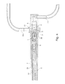
- FIG. 1 shows the shut-off valve with actuator, insulation and valve piece, reduced in longitudinal section.
- FIGS. 2 to 4 are partial enlargements FIG. 1 , in which FIG. 2 essentially shows the actuator at one end of the shut-off valve, FIG. 3 the adjoining the actuator section, referred to as adapter piece, with the seal against the cryogenic medium and FIG. 4 the valve piece at the other end of the shut-off valve.
- a not shown cryotank for high pressure storage of hydrogen is installed in a not shown motor vehicle. This serves as a fuel for the supply of a motor vehicle driving, not shown, internal combustion engine.
- the hydrogen is in the cryotank in an aggregate state, in supercritical form.
- a not shown extraction device for hydrogen is installed in the cryogenic tank, this supplies the internal combustion engine with hydrogen via two not shown extraction lines.
- Each of the sampling lines is close to the tank with one in the FIGS. 1 to 4 drawn, actuated by an electromagnetic actuator 14 check valve 1 is provided.
- the removal device is also used for filling the container with cryogenically stored fuel via the withdrawal lines.
- shut-off valve 1 For filling the cryotank with hydrogen or the removal of hydrogen from this at least one shut-off valve 1 must be opened. For its electromagnetic actuator 14 is energized and the actual refueling process or removal can be performed.
- shut-off valve 1 can be used both in a removal device and in a filling device for cryogenically stored fuel. Furthermore, such a device can also fulfill both functions.
- a cryotank which is designed as a double-shell vacuum container
- the shut-off valve 1 between the outer and the inner container in the vacuum insulation are located, in particular, for example, via a welded holding device inserted into an outer container 57 and fixed there.
- the shut-off valve 1 can also be welded or otherwise attached to both containers. Inside at the outer container and outside at the inner container. In all cases, such a construction is in any case favorable for the package of the motor vehicle, namely, the shut-off valve 1 does not require any extra space to be reserved.
- shut-off valve 1 is thereby housed as possible close to the tank, with the advantage that in a safety-critical situation, the hydrogen extraction can be blocked directly on Kryotank itself and not a remote from the cryogenic tank line is blocked. It can be between cryotank and shut-off valve so advantageously no breakage of the removal / filling occur.
- the FIGS. 1 to 4 It consists of a valve housing 2 with completely removable valve inserts including a rotatable ball 3 as a seal body, a valve piston 4, a valve seat 5 with static seat seal 6, a coupling rod 7 with an upper and a lower pressure piece 8, 9, and Insulating pieces 10, 35 made of Teflon in and around the coupling rod 7 of the shut-off valve 1, which reduce a free volume within the shut-off valve 1 to reduce the heat input into the cryogenic fluid, and the coupling rod 7 lead.
- the upper valve housing 12 ' as part of the housing 2, is connected to a valve tube 11 and this in turn to the lower valve housing 12, which contains the actual cryogenic valve unit.
- the upper valve housing 12 ' is connected to a wall 13 of a vacuum envelope, which surrounds the shut-off valve 1 and isolated from the environment.
- An armature spindle 19 and the coupling rod 7 can transmit high valve forces to the valve piston 4, because the inner Teflon insulator 10 as a support against buckling the coupling rod 7 acts.
- misalignment and angular tolerances of coupling rod 7 and valve piston 4 does not significantly affect the sealing surface, for Example in the form of an uneven impression.
- An electromagnetic actuator 14 is seated outside the vacuum envelope and is connected by means of an adapter piece 15, which has a flange 16 on the side of the actuator 14 with the shut-off valve 1.
- an adapter piece 15 which has a flange 16 on the side of the actuator 14 with the shut-off valve 1.
- a dynamic seal consisting of a double O-ring / support ring seal 52, 53 is integrated.
- the purely electromagnetic drive of the shut-off valve 1 is a double-coil permanent magnet actuator 14.
- the closing force for the shut-off valve 1 is in this case not by a spring, but by a built-in actuator 14 closing element, a permanent magnet 18, for example, neodymium ( NdFeB with coating), applied and transferred by means of an armature spindle 19, an actuator spindle 20 and the coupling rod 7 on the valve seat 5.
- the permanent magnet 18 is received between two anchor plates 21 a, 21 b and mounted with these on the guided in plain bearing bushings 22 armature spindle 19.
- An upper and a lower magnet housing 23, 24 each receives a coil, a so-called holding coil 25 in the upper magnet housing 23 and a so-called compensation coil 26 in the lower magnet housing 24.
- a pole ring 27 In between a pole ring 27 is placed.
- Magnetic housing 23, 24, pole ring 27 and anchor plates 21 are made of magnetizable material.
- the actuator 14 includes a pneumatic damping device, from one attached to the end of the armature spindle 19, the housing 33 of the actuator 14 open toward cup-shaped piston 28. By air compression relative to the housing 33, the force surges that occur when switching the shut-off valve 1, reduced ,
- a connecting element 34 is mounted for the electrical power connection.
- the operating principle of the actuator 14 is described as follows: The magnetic field of the permanent magnet 18 runs in the closed state of the shut-off valve 1 mainly via the lower anchor plate 21 b, the lower magnet housing 24, via the pole ring 27 on the upper anchor plate 21 a. About the height of a Abstimmefficiency 29 between the flange 16 and actuator 14, this is biased during assembly so that a small air gap of about 0.1 to 0.2 mm between the lower anchor plate 21 b and lower magnet housing 24 remains.
- the magnetic field of the permanent magnet 18 attempts to produce the ring closure described above with contact between the lower armature plate 21 b and the lower magnet housing 24 and thus generates a force in the direction of the valve seat 5.
- This configuration and the bias described above results in a contact pressure of the ball 3 on the Valve seat 5 of about 1500 to 1600 N.
- both coils 25, 26 are energized with a time offset in the normal case.
- the compensation coil 26 is turned on. This counteracts the magnetic field of the permanent magnet 18 and moves it into the lower armature plate 21 b, so that the coil field flows mainly through the lower magnet housing 24.
- the attraction between anchor plates 21 a, 21 b and lower magnet housing 24 is so far weakened that during later energizing the holding coil 25, while still energized compensation coil 26, the armature spindle 19 together with anchor plates 21 a, 21 b and permanent magnet 18 in the direction of the housing cover 34th is moved and the shut-off valve 1 thus opens.
- the upper anchor plate 21 a as in the FIG.
- the electromagnetic actuator 14 should not be exposed to such low temperatures, moreover, insulation is needed to minimize the heat input, which reduces the heat transfer from the actuator 14 to the valve housing 2 and other functional groups. Therefore, the closing operation force transmitting coupling rod 7 is formed of a heat-insulating plastic. Outside the coupling rod 7, in the remaining space in the central part of the one-piece valve housing 2, around the coupling rod 7 around, another heat transfer preventing insulation device, for example made of the plastics PTFE or PU introduced. This insulating cylinder 35, is also formed so that the valve housing 2 is almost completely filled with material, which causes that in the valve housing 2 as little as possible space is filled with gas.
- the adapter piece 15 with the flange 16 is sealed gas-tight relative to the valve housing 2, both between mutually movable, and between mutually fixed parts.
- the gas-loaded part of the shut-off valve 1 is closed in a gas-tight manner relative to the actuator 14 by means of O-rings.
- This principle of double sealing by two barriers in each case has the advantage that potential leaks can be sensed and discharged in the intermediate space between the first and second sealing barriers via a detection line 56.
- the first and the second dynamic sealing of the shut-off valve 1 against gas leakage consist of an O-rings 50, 51 between flange 16 and actuator spindle 20, wherein in the first dynamic sealing of the O-ring 50 is still secured by a support ring 52 against gap extrusion.
- the O-rings of the two dynamic seals are held by integrated in the adapter piece 15, the actuator spindle 20 leading plain bearing bushes 53.
- the first and the second barrier of the two static seals each forms an O-ring 54, 55 between the upper valve housing 12 'and adapter piece 15.
- a detection line 56 each have a cavity between the actuator spindle 20 and adapter piece 15 in the case of the two dynamic seals and adapter piece 15 and upper valve housing 12' in the case tapped the two static seals.
- the seals are placed in the upper valve housing 12 ', which is not exposed to cryogenic temperatures.
- For the entire valve body 2 is pressure-resistant and made in one piece.
- the free volume of the shut-off valve 1 is reduced by the two insulating pieces 10, 35 in the coupling rod 7und the outside around the coupling rod 7 around to a minimum.
- the diameter of the actuator spindle 20 is chosen to be as small as possible, since its cross-sectional area represents the contact surface for the resulting compressive forces, which increase with the square of the diameter and which must withstand the dynamic seal. Furthermore, these must also be overcome by the actuator 14.
- For the actuator spindle 20 is made of a high-strength, hydrogen-resistant material.
- the actuator spindle 20 is guided over a large length, through the two integrated into the adapter piece 15 plain bearing bushings 53. Furthermore, smooth surfaces, both on the actuator spindle 20, for example finely turned and polished, as well as the adapter piece 15, in the groove for the dynamic seal, necessary to achieve reliable tightness.
- the location of the dynamic seal at the "warm" valve end eliminates the need for cryogenic sealing materials, such as bellows, and standard materials for high pressure applications.
- the elimination of bellows which would be common and necessary for sealing under cryogenic conditions, means significantly lower resulting compressive forces, since the effective area of bellows is significantly greater.
- no additional spring stiffnesses of the bellows are to be considered, which allows a lower performance of the valve drive and significantly lower manufacturing costs and a longer life than a welded bellows unit.
Landscapes
- Engineering & Computer Science (AREA)
- General Engineering & Computer Science (AREA)
- Mechanical Engineering (AREA)
- Lift Valve (AREA)
- Magnetically Actuated Valves (AREA)
- Safety Valves (AREA)
Abstract
Description
- Die Erfindung betrifft ein Absperrventil für einen Behälter zur Speicherung von Kraftstoff als kondensiertes Gas, insbesondere für einen Kryotank, nach dem Oberbegriff des ersten Anspruchs. Solche Absperrventile werden unter anderem mit elektromagnetischen Aktuatoren als Linearantrieb zum Öffnen und Schließen ausgestattet.
- Es ist zusätzlich bereits bekannt, Kraftfahrzeuge zum Beispiel mit Wasserstoff oder Erdgas anzutreiben und diesen Treibstoff als kondensiertes Gas in einem Behälter im Kraftfahrzeug zu speichern. Zu dieser verflüssigten Speicherung sind spezielle druckfeste Behälter notwendig, die aufgrund der tiefen Speichertemperaturen eine sehr gute Isolation besitzen sollten. Dabei ist bekannt, zur Vermeidung von Wärmeeintrag.aus der Umgebung, doppelwandige, vakuumisolierte Behälter zu verwenden. In einer Ausführungsform als Hochdruckbehälter liegt deren Betriebstemperaturbereich zwischen 30K und 358 K, bei regulärem Betriebsdruck zwischen 0 bar und 350 bar. Solche mobilen kryogenen Hochdruckspeicher besitzen nach derzeitigem Stand mindestens eine Entnahmeeinrichtung für den kryogen gespeicherten Kraftstoff, die mindestens aus einer Entnahmeleitung mit einem tanknah untergebrachten Absperrventil besteht.
- Die
EP 0 535 394 B1 beschreibt ein Magnetventil für tiefkalte verflüssigte Gase als Absperrventil für ein Entnahmesystem für Flüssigwasserstoff aus einem Speichertank. Eine Druckfeder übernimmt dort die Schließfunktion, während das Öffnen des Kryoventils durch Bestromung eines Spulenkörpers erfolgt, was bewirkt, dass zuerst ein Oberanker und dann ein Unteranker mit einem Verschlussorgan entgegen der Kraft der Druckfeder vom Ventilsitz weg bewegt werden. Sollte diese Druckfeder im Betrieb versagen, ist das Ventil nicht mehr geschlossen und der Tankinhalt mit der Entnahmeleitung verbunden. - Die
EP 1 801 478 A2 beschreibt ein Absperrventil für einen Behälter für kryogen gespeicherten Kraftstoff das mittels Druckluft betätigt wird, was bei einer Anwendung im Kraftfahrzeug das Vorhandensein einer Druckluftanlage voraussetzt. - Im Allgemeinen können mit Konzepten mit elektromagnetischem Ventilantrieb für die Verwendung im Zusammenhang mit tiefkalten Gasen im Kraftfahrzeug bei akzeptabler Anzugs- und Halteleistung nur vergleichsweise geringe Kräfte eines Schließelements, zum Beispiel einer Feder, überwunden werden. Durch die niedrigen zur Verfügung stehenden Dichtkräfte am Ventilsitz und den massiven Elastizitätsverlust aller bekannten Dichtungsmaterialien im kryogenen Bereich, weisen diese Ventile bei tiefkaltem Betrieb sehr schlechte interne Dichtheiten auf. Zudem steigt die Partikelempfindlichkeit aufgrund der Relevanz der sehr genauen Dichtungsoberflächen stark an und ein Einsatz von Filterelementen ist erforderlich, welche aber wiederum den Druckverlust im Entnahme- und Betankungsstrom deutlich erhöhen.
- Aufgabe der vorliegenden Erfindung ist es, ein Absperrventil für einen Behälter zur Speicherung von Kraftstoff als kondensiertes Gas, insbesondere für einen Kryotank mit einem elektromagnetischen Aktuator bereitzustellen, das ohne spezielle für kryogene Anwendung gewöhnlich notwendige Dichtungselemente auskommt, sondern in dem Standarddichtelemente für Hochdruckanwendung zur Anwendung kommen können.
- Die Aufgabe der Erfindung wird durch die Merkmale des Anspruchs 1 gelöst. Vorteilhafte Aus- und Weiterbildungen der Erfindung sind Inhalt der abhängigen Ansprüche.
- Nach der Erfindung ist ein Absperrventil für einen Behälter zur Speicherung von Kraftstoff als komprimiertes kryogenes oder kondensiertes Gas, insbesondere für einen Kryohochdrucktank, für einen mit kryogen gespeichertem Kraftstoff betreibbaren Verbraucher, insbesondere eine Brennkraftmaschine eines Kraftfahrzeugs, wobei der Behälter eine Entnahmeeinrichtung für den kryogen gespeicherten Kraftstoff besitzt, mindestens bestehend aus einer Entnahmeleitung mit dem Absperrventil (1), das durch einen Aktuator betätigt wird und einen kalten und einen warmen Ventilteil besitzt, dadurch gekennzeichnet, dass zwischen warmem und kaltem Ventilteil ein Übergangsteil zum Wärmeabbau vorhanden ist und dass im warmen Ventilteil oder im Übergangsteil, am mit dem warmen Ventilteil verbundenen Ende, ein Adapterstück eingefügt ist, das eine Dichtungseinrichtung enthält, die einen GasAustritt vom kalten Ventilteil her in die Umgebung oder in den Aktuator verhindert.
- Eine Trennung des kalten Ventilteils vom warmen Aktuatorteil durch ein Adapterstück mit einer Dichtungseinrichtung hat den Vorteil, dass die dynamische und die statische Abdichtung des kalten Ventilteils einfach an das warme Ventilende verlegt werden kann. So sind keine kryogenen Dichtungsmaterialien, wie Faltenbälge, notwendig, es können Standardmaterialien für Hochdruck-Anwendung verwendet werden, was deutlich geringere resultierende Druckkräfte bewirkt. Es sind keine zusätzlichen Federsteifigkeiten der Bälge zu berücksichtigen, was die nötige Leistung des Aktuators geringer hält und der Verzicht auf eine geschweißte Faltenbalgeinheit stellt eine deutlich günstigere Lösung mit besserer Lebensdauer dar.
- Eine bevorzugte Ausführung der Erfindung ist dadurch gekennzeichnet, dass die Dichtungseinrichtung im Wesentlichen aus Kunststoff- und/oder Gummidichtungen, insbesondere aus O-Ringen, besteht, was eine besonders preiswerte und zuverlässige Abdichtungsart darstellt.
- Weitere bevorzugte Ausführungen der Erfindung zeichnen sich dadurch aus, dass die Dichtungseinrichtung aus je zwei statischen und dynamischen Dichtstellen mit dazwischen liegendem Hohlraum besteht. Wenn dann der Hohlraum auf Gasdichtheit überwacht wird, insbesondere durch einen Sensor, insbesondere indem Leckgas mittels einer Detektionsleitung aus dem Hohlraum heraus abgeführt werden kann, insbesondere in einen auf Gaskonzentration überwachten Raum, ist die Funktionssicherheit des Absperrventils bezüglich Dichtheit besonders gewährleitet.
- Eine vorteilhafte Ausführung der Erfindung zeichnet sich dadurch aus, dass eine erste und eine zweite dynamische Abdichtung gegen Gasaustritt, bestehend aus O-Ringen, zwischen Adapterstück und Aktuatorspindel eingebaut ist, wobei bei der ersten dynamischen Abdichtung der O-Ring durch einen Stützring und bei der zweiten dynamischen Abdichtung der O-Ring durch eine Buchse gegen Spaltextrusion gesichert ist. Eine noch bessere und zuverlässigere Abdichtung wie vorstehend wird erreicht, wenn zusätzlich die O-Ringe der beiden dynamischen Abdichtungen zwischen zwei im Adapterstück integrierte, die Aktuatorspindel führende Gleitlagerbuchsen eingebracht sind.
- Bei weiteren vorteilhaften Ausführungen der Erfindung ist eine erste und eine zweite statische Abdichtung gegen Gasaustritt, bestehend jeweils aus einem O-Ring zwischen oberem Ventilgehäuse und Adapterstück eingebaut. Dabei ist weiterhin von Vorteil, wenn zwischen einer jeweils ersten und zweiten Barriere der dynamischen und der statischen Abdichtungen durch eine Detektionsleitung jeweils ein Hohlraum zwischen Aktuatorspindel und Adapterstück im Fall der beiden dynamischen Dichtungen und zwischen Adapterstück und oberem Ventilgehäuse im Fall der beiden statischen Dichtungen abgegriffen wird. So kann auf einfache Weise ein vorhandenes Detektionssystem, insbesondere durch mindestens einen Sensor in der Detektionsleitung, potentielle Leckagen der Abdichtungen erkennen.
- Bei einer weiteren bevorzugten Ausführung der Erfindung besitzt das Absperrventil ein Verschlussorgan mit räumlich runder Oberfläche, insbesondere kugelförmiger Oberfläche, das so gegen einen Öffnungsquerschnitt eines rohrförmigen Ventilsitzes in Fortsetzung eines Einlasskanals für kryogen gespeicherten Kraftstoff gepresst wird, dass eine zu einem Auslasskanal hin gas- und flüssigkeitsdichte Verbindung zwischen Verschlussorgan und rohrförmigem Ventilsitz aufrechterhalten wird. Eine solche Ventilausführung ist vorteilhafterweise in kleiner Dimension auszuführen bei Gewährleistung einer zuverlässigen Funktion. Wenn dann zwischen Aktuatorspindel und Verschlussorgan ein mindestens Längskraft übertragendes inneres Rohr, insbesondere aus Kunststoff, als Koppelstange eingebracht ist, das innen und außen eine Wärmeübergang verhindernde Isoliereinrichtung besitzt, ist auf einfache Weise der mit Wasserstoff beaufschlagte, kalte Bereich des Ventils vom warmen Bereich des Ventils getrennt und wärmeisoliert. Diese thermische Abkopplung durch Isolation, auch der Koppelstange, macht es möglich, den Aktuator im warmen Bereich anzubinden. Der innere Teflon-Isolator der Koppelstange wirkt dabei auch als Stütze gegen Knicken der Koppelstange, deshalb können über die Aktuatorspindel und die Koppelstange vorteilhafterweise hohe Ventilkräfte auf den Ventilkolben übertragen werden. Durch die nicht starre Verbindung zwischen unterem Druckstück der Koppelstange und dem Ventilkolben, welcher sehr genau durch die beiden Gleitringe im unteren Ventilgehäuse geführt wird, wirken sich Achsversatz und Winkeltoleranzen von Koppelstange und Ventilkolben nur gering auf die Dichtfläche aus.
- Eine weitere vorteilhafte Ausführung der Erfindung ist dadurch gekennzeichnet, dass die vom Aktuator auf die Koppelstange Kraft übertragende Aktuatorspindel aus einer hochfesten Legierung, insbesondere einer Nickel-Basislegierung, zum Beispiel lnconel 718, besteht.
- Bei einer weiteren Ausfürungsform der Erfindung wird die Entnahmeeinrichtung auch als Befülleinrichtung für kryogen gespeicherten Kraftstoff genutzt. Das macht den Tankaufbau besonders einfach.
- Im Folgenden wird die Erfindung anhand eines bevorzugten Ausführungsbeispiels weiter erläutert. Alle Figuren zeigen dasselbe Absperrventil einer Anlage zur Speicherung von kondensiertem Gas eines Kraftfahrzeugs mit einem elektromagnetischen Aktuator gemäß der Erfindung.
Figur 1 zeigt das Absperrventil mit Aktuator, Isoliereinrichtung und Ventilstück, verkleinert im Längsschnitt. DieFiguren 2 bis 4 sind Teilvergrößerungen ausFigur 1 , wobeiFigur 2 im wesentlichen den Aktuator am einen Ende des Absperrventils zeigt,Figur 3 das an den Aktuator anschließende Teilstück, als Adapterstück bezeichnet, mit der Abdichtung gegen das kryogene Medium undFigur 4 das Ventilstück am anderen Ende des Absperrventils. - In einem nicht gezeichneten Kraftfahrzeug ist ein nicht gezeichneter Kryotank zur Hochdruckspeicherung von Wasserstoff eingebaut. Dieser dient als Kraftstoff zur Versorgung einer das Kraftfahrzeug antreibenden, nicht gezeichneten, Brennkraftmaschine. Der Wasserstoff liegt im Kryotank in einem Aggregatzustand, in überkritischer Form vor. Eine nicht gezeichnete Entnahmeeinrichtung für Wasserstoff ist in den Kryotank eingebaut, diese versorgt über zwei nicht gezeichnete Entnahmeleitungen die Brennkraftmaschine mit Wasserstoff.
- Jede der Entnahmeleitungen ist tanknah mit einem in den
Figuren 1 bis 4 gezeichneten, durch einen elektromagnetischen Aktuator 14 betätigbaren Absperrventil 1 versehen. Zusätzlich wird die Entnahmeeinrichtung über die Entnahmeleitungen auch zum Befüllen des Behälters mit kryogen gespeichertem Kraftstoff benutzt. - Für das Befüllen des Kryotanks mit Wasserstoff oder die Entnahme von Wasserstoff aus diesem muss mindestens ein Absperrventil 1 geöffnet werden. Dafür wird dessen elektromagnetischer Aktuator 14 bestromt und der eigentliche Betankungsvorgang oder die Entnahme kann durchgeführt werden.
- Ein solches Absperrventil 1 ist sowohl in einer Entnahmeeinrichtung als auch in einer Befülleinrichtung für kryogen gespeicherten Kraftstoff verwendbar. Des Weiteren kann eine solche Einrichtung auch beide Funktionen erfüllen. Vorteilhafterweise kann sich bei einem Kryotank, der als zweischaliger Vakuumbehälter ausgebildet ist, das Absperrventil 1 zwischen dem Außen- und dem Innenbehälter im Bereich der Vakuumisolation befinden, insbesondere zum Beispiel über eine angeschweißte Haltevorrichtung in einen Außenbehälter 57 eingesetzt und dort befestigt. Das Absperrventil 1 kann auch an beiden Behältern angeschweißt bzw. andersartig befestigt sein. Innen am Außenbehälter und außen am Innenbehälter. In allen Fällen ist eine solche Bauweise auf jeden Fall günstig fürs Package des Kraftfahrzeugs, das Absperrventil 1 benötigt nämlich für sich keinen extra zu reservierenden Bauraum.
- Außerdem ist das Absperrventil 1 dadurch möglichst tanknah untergebracht, mit dem Vorteil, dass in einer sicherheitskritischen Lage die Wasserstoffentnahme direkt am Kryotank selbst gesperrt werden kann und nicht eine vom Kryotank entfernte Leitung gesperrt wird. Es kann zwischen Kryotank und Absperrventil so vorteilhafterweise kein Bruch der Entnahme-/Befüllleitung auftreten.
- Die
Figuren 1 bis 4 zeigen das Absperrventil 1. Es besteht aus einem Ventilgehäuse 2 mit komplett demontierbaren Ventileinsätzen einschließlich einer verdrehbaren Kugel 3 als Dichtungskörper, einem Ventilkolben 4, einem Ventilsitz 5 mit statischer Sitzdichtung 6, einer Koppelstange 7 mit einem oberen und einem unteren Druckstück 8, 9, sowie Isolierstücken 10, 35 aus Teflon in und um die Koppelstange 7 des Absperrventils 1, welche ein freies Volumen innerhalb des Absperrventils 1 reduzieren, um den Wärmeeintrag in das kryogene Fluid zu reduzieren, sowie die Koppelstange 7 führen. Das obere Ventilgehäuse 12', als Teil des Gehäuses 2, ist mit einem Ventilrohr 11 verbunden und dieses wiederum mit dem unteren Ventilgehäuse 12, das die eigentliche kryogene Ventileinheit enthält. Das obere Ventilgehäuse 12' ist mit einer Wand 13 einer Vakuumhülle, welche das Absperrventil 1 umgibt und gegen die Umgebung isoliert, verbunden. - Eine Ankerspindel 19 und die Koppelstange 7 können hohe Ventilkräfte auf den Ventilkolben 4 übertragen, weil der innere Teflon-Isolator 10 auch als Stütze gegen Knicken der Koppelstange 7 wirkt. Durch eine nicht starre Verbindung zwischen unterem Druckstück 9 der Koppelstange 7 und dem Ventilkolben 4, welcher sehr genau durch zwei Gleitringe 36 im unteren Ventilgehäuse 12 geführt wird, wirken sich Achsversatz und Winkeltoleranzen von Koppelstange 7 und Ventilkolben 4 nicht wesentlich auf die Dichtfläche aus, zum Beispiel in Form einer ungleichmäßigen Einprägung.
- Ein elektromagnetischer Aktuator 14 sitzt außerhalb der Vakuumhülle und ist mittels eines Adapterstücks 15, welches auf der Seite zum Aktuator 14 einen Flansch 16 aufweist mit dem Absperrventil 1 verbunden. In diesem Adapterstück 15 ist eine dynamische Abdichtung bestehend aus einer doppelten O-Ring-/Stützringabdichtung 52, 53 integriert.
- Der rein elektromagnetische Antrieb des Absperrventils 1 ist ein Doppelspulen-Permanentmagnet-Aktuator 14. Die Schließkraft für das Absperrventil 1 wird in diesem Fall nicht von einer Feder, sondern von einem in den Aktuator 14 integrierten Schließelement, einem Permanentmagneten 18, zum Beispiel aus Neodym (NdFeB mit Beschichtung), aufgebracht und mittels einer Ankerspindel 19, einer Aktuatorspindel 20 und der Koppelstange 7 auf den Ventilsitz 5 übertragen. Der Permanentmagnet 18 ist zwischen zwei Ankerplatten 21 a, 21 b aufgenommen und mit diesen auf der in Gleitlagerbuchsen 22 geführten Ankerspindel 19 montiert. Ein oberes und ein unteres Magnetgehäuse 23, 24 nimmt je eine Spule auf, eine so genannte Haltespule 25 im oberen Magnetgehäuse 23 und eine so genannte Kompensationsspule 26 im unteren Magnetgehäuse 24. Dazwischen ist ein Polring 27 platziert. Magnetgehäuse 23, 24, Polring 27 und Ankerplatten 21 bestehen aus magnetisierbarem Material. Weiterhin enthält der Aktuator 14 eine pneumatische Dämpfungseinrichtung, aus einem am Ende der Ankerspindel 19 befestigten, zum Gehäuse 33 des Aktuators 14 hin offenen, topfartigen Kolben 28. Durch Luftkompression gegenüber dem Gehäuse 33 werden die Kraftstöße, die beim Schalten des Absperrventils 1 entstehen, reduziert.
- Außen am Gehäuse 33 des elektromagnetischen Aktuators 14 ist ein Verbindungselement 34 für den elektrischen Stromanschluss angebracht. Das Funktionsprinzip des Aktuators 14 ist folgendermaßen zu beschreiben: Das Magnetfeld des Permanentmagneten 18 läuft im geschlossenen Zustand des Absperrventils 1 hauptsächlich über die untere Ankerplatte 21 b, das untere Magnetgehäuse 24, über den Polring 27 auf die obere Ankerplatte 21 a. Über die Höhe einer Abstimmscheibe 29 zwischen Flansch 16 und Aktuator 14 wird dieser bei der Montage so vorgespannt, dass ein kleiner Luftspalt von ca. 0,1 bis 0,2 mm zwischen unterer Ankerplatte 21 b und unterem Magnetgehäuse 24 bleibt. Das Magnetfeld des Permanentmagneten 18 versucht, den oben beschriebenen Ringschluss mit Kontakt zwischen unterer Ankerplatte 21 b und unterem Magnetgehäuse 24 herzustellen und erzeugt somit eine Kraft in Richtung Ventilsitz 5. Mit dieser Konfiguration und der oben beschriebenen Vorspannung ergibt sich eine Anpresskraft der Kugel 3 auf den Ventilsitz 5 von ca. 1500 bis 1600 N.
- Zum Öffnen des Absperrventils 1 werden im Normalfall beide Spulen 25, 26 zeitlich versetzt bestromt. Zuerst wird die Kompensationsspule 26 eingeschaltet. Diese wirkt dem Magnetfeld des Permanentmagneten 18 entgegen und verschiebt dieses in die untere Ankerplatte 21 b, so dass das Spulenfeld hauptsächlich durch das untere Magnetgehäuse 24 fließt. Damit ist die Anziehungskraft zwischen Ankerplatten 21 a, 21 b und unterem Magnetgehäuse 24 so weit geschwächt, dass beim späteren Bestromen der Haltespule 25, bei weiterhin bestromter Kompensationsspule 26, die Ankerspindel 19 samt Ankerplatten 21 a, 21 b und Permanentmagnet 18 in Richtung Gehäusedeckel 34 bewegt wird und das Absperrventil 1 somit öffnet. Wenn die obere Ankerplatte 21 a, wie in der
Figur 2 dargestellt, am oberen Magnetgehäuse 23 anliegt, wird die Kompensationsspule 26 abgeschaltet und die Haltespule 25 auf einen schwächeren Haltestrom herunter geregelt. Der Luftspalt zwischen unterer Ankerplatte 21 b und unterem Magnetgehäuse 24 ist nun groß genug, dass eine niedrige Halteleistung ausreicht, um das Absperrventil 1 sicher offen zu halten. Gleichzeitig ist dieser Luftspalt aber klein genug, dass noch genügend Restkraft durch das Permanentmagnetfeld 18 vorhanden ist, damit das Absperrventil 1 bei Abschalten des Haltespulenstroms aufgrund dieser Restkraft wieder schließt. Wird also bei Betriebsende die Haltespule 25 abgeschaltet, versucht das Magnetfeld des Permanentmagneten 18 den Ring über Ankerplatten 21 a, 21 b, unteres Magnetgehäuse 24 und Polring 27 wieder zu schließen und die Ankerspindel 19 bewegt sich vom Gehäusedeckel 34 weg und schließt das Absperrventil 1. Je kleiner dabei der verbleibende Luftspalt zwischen unterer Ankerplatte 21 b und unterem Magnetgehäuse 24 wird, desto größer wird die Magnetkraft. - Das Verschlussorgan des Absperrventils 1 ist, wie alle weiteren Elemente des unteren Ventilgehäuses 12, zum Beispiel Einlass- und Auslasskanal 41, 42, sehr tiefen Temperaturen des kryogen gespeicherten Kraftstoffs ausgesetzt. Diese liegen bei bis zu -240 Grad Celsius. Der elektromagnetische Aktuator 14 sollte solch niedrigen Temperaturen nicht ausgesetzt werden, außerdem ist zur Minimierung des Wärmeeintrags eine Isolierung nötig, die die Wärmeübertragung vom Aktuator 14 auf das Ventilgehäuse 2 und sonstige Funktionsgruppen mindert. Daher ist die Schließbetätigungskraft übertragende Koppelstange 7 aus einem wärmeisolierenden Kunststoff ausgebildet. Außerhalb der Koppelstange 7, ist in den verbleibenden Raum im Mittelteil des einstückigen Ventilgehäuses 2, um die Koppelstange 7 herum, eine weiteren Wärmeübergang verhindernde Isoliereinrichtung, zum Beispiel aus den Kunststoffen PTFE oder PU, eingebracht. Dieser Isolationszylinder 35, ist auch so ausgebildet, dass das Ventilgehäuse 2 fast völlig mit Material ausgefüllt ist, was bewirkt, dass im Ventilgehäuse 2 so wenig wie möglich Freiraum mit Gas gefüllt ist.
- Das Adapterstück 15 mit dem Flansch 16 ist gegenüber dem Ventilgehäuse 2 gasdicht abgedichtet und zwar sowohl zwischen zueinander beweglichen, als auch zwischen zueinander feststehenden Teilen. Durch jeweils zwei dynamische und zwei statische Abdichtungen wird mittels O-Ringen der gasbeaufschlagte Teil des Absperrventils 1 gasdicht gegenüber dem Aktuator 14 verschlossen. Dieses Prinzip der doppelten Abdichtung durch jeweils zwei Barrieren hat den Vorteil, dass im Zwischenraum zwischen erster und zweiter Dichtungsbarriere über eine Detektionsleitung 56 potentielle Leckagen sensiert und abgeleitet werden können.
- Die erste und die zweite dynamische Abdichtung des Absperrventils 1 gegen Gasaustritt bestehen aus einem O-Ringen 50, 51 zwischen Flansch 16 und Aktuatorspindel 20, wobei bei der ersten dynamischen Abdichtung der O-Ring 50 noch durch einen Stützring 52 gegen Spaltextrusion gesichert ist. Die O-Ringe der beiden dynamischen Abdichtungen werden durch im Adapterstück 15 integrierte, die Aktuatorspindel 20 führende Gleitlagerbuchsen 53 gehalten. Die erste und die zweite Barriere der beiden statischen Abdichtungen bildet je ein O-Ring 54, 55 zwischen oberem Ventilgehäuse 12' und Adapterstück 15. Zwischen der jeweils ersten und zweiten Barriere der dynamischen und der statischen Abdichtungen wird durch eine Detektionsleitung 56 jeweils ein Hohlraum zwischen Aktuatorspindel 20 und Adapterstück 15 im Fall der beiden dynamischen Dichtungen und zwischen Adapterstück 15 und oberem Ventilgehäuse 12' im Fall der beiden statischen Dichtungen abgegriffen.
- Die Abdichtungen sind im oberen Ventilgehäuse 12' platziert, welches keinen kryogenen Temperaturen ausgesetzt ist. Dafür ist das gesamte Ventilgehäuse 2 druckfest und einstückig ausgeführt. Das freie Volumen des Absperrventils 1 ist durch die beiden Isolierstücke 10, 35 in der Koppelstange 7und außen um die Koppelstange 7 herum auf ein Minimum reduziert. Der Durchmesser der Aktuatorspindel 20 ist so klein wie möglich gewählt, da deren Querschnittsfläche die Angriffsfläche für die resultierenden Druckkräfte darstellt, welche mit dem Quadrat des Durchmessers steigen und denen die dynamische Dichtung standhalten muss. Des Weiteren müssen diese auch vom Aktuator 14 überwunden werden. Dafür ist die Aktuatorspindel 20 aus einem hochfesten, wasserstoffbeständigen Werkstoff ausgeführt. Um die notwendige Dichtheit gegenüber großen Drücken zu erzielen und die großen Kräfte sicher zu übertragen, ist die Aktuatorspindel 20 über eine große Länge geführt, durch die zwei in das Adapterstück 15 integrierte Gleitlagerbuchsen 53. Des Weiteren sind glatte Oberflächen, sowohl auf der Aktuatorspindel 20, zum Beispiel feingedreht und poliert, als auch beim Adapterstück 15, in der Nut für die dynamische Dichtung, notwendig, um zuverlässige Dichtigkeit zu erzielen. Durch die Lage der dynamischen Abdichtung am "warmen" Ventilende sind keine kryogenen Dichtungsmaterialien, wie Faltenbälge, notwendig, es können Standardmaterialien für Hochdruck-Anwendung verwendet werden. Der Entfall von Faltenbälgen, die für Abdichtungen unter Kryo-Bedingungen üblich und notwendig wären, bedeutet deutlich geringere resultierende Druckkräfte, da die Wirkfläche von Faltenbälgen deutlich größer ist. Außerdem dass keine zusätzlichen Federsteifigkeiten des Balgs zu berücksichtigen sind, was eine geringere Leistung des Ventilantriebs ermöglicht und deutlich günstigere Fertigungskosten und eine längere Lebensdauer als bei einer geschweißten Faltenbalgeinheit.
Claims (12)
- Absperrventil (1) für einen Behälter zur Speicherung von Kraftstoff als komprimiertes kryogenes oder kondensiertes Gas, insbesondere für einen Kryohochdrucktank, für einen mit kryogen gespeichertem Kraftstoff betreibbaren Verbraucher, insbesondere eine Brennkraftmaschine eines Kraftfahrzeugs, wobei der Behälter eine Entnahmeeinrichtung für den kryogen gespeicherten Kraftstoff besitzt, mindestens bestehend aus einer Entnahmeleitung mit dem Absperrventil (1), das durch einen Aktuator betätigt wird und einen kalten und einen warmen Ventilteil besitzt, dadurch gekennzeichnet, dass zwischen warmem und kaltem Ventilteil ein Übergangsteil zum Wärmeabbau vorhanden ist und dass im warmen Ventilteil oder im Übergangsteil, am mit dem warmen Ventilteil verbundenen Ende, ein Adapterstück eingefügt ist, das eine Dichtungseinrichtung enthält, die einen Gasaustritt vom kalten Ventilteil her in die Umgebung oder in den Aktuator verhindert.
- Absperrventil (1) nach Anspruch 1, dadurch gekennzeichnet, dass die Dichtungseinrichtung im Wesentlichen aus Kunststoff- und/oder Gummidichtungen, insbesondere aus O-Ringen, besteht.
- Absperrventil (1) nach Anspruch 1 oder 2, dadurch gekennzeichnet, dass die Dichtungseinrichtung aus je zwei statischen und dynamischen Dichtungen mit dazwischen liegendem Hohlraum besteht.
- Absperrventil (1) nach Anspruch 3, dadurch gekennzeichnet, dass der Hohlraum auf Gasdichtheit überwacht wird, insbesondere durch einen Sensor, insbesondere indem Leckgas mittels einer Detektionsleitung aus dem Hohlraum heraus abgeführt werden kann, insbesondere in einen auf Gaskonzentration überwachten Raum.
- Absperrventil (1) nach einem der Ansprüche 1 bis 4, dadurch gekennzeichnet, dass eine erste und eine zweite dynamische Abdichtung gegen Gasaustritt, bestehend aus O-Ringen (50, 51), zwischen Adapterstück (15) und Aktuatorspindel (20) eingebracht ist, wobei bei der ersten dynamischen Abdichtung der O-Ring (50) durch einen Stützring (52) und bei der zweiten dynamischen Abdichtung der O-Ring (51) durch eine Buchse (53a) gegen Spaltextrusion gesichert ist.
- Absprerrventil (1) nach Anspruch 5, dadurch gekennzeichnet, dass die O-Ringe (50, 51) der beiden dynamischen Abdichtungen zwischen zwei im Adapterstück (15) integrierte, die Aktuatorspindel (20) führende Gleitlagerbuchsen (53) eingebracht sind.
- Absperrventil (1) nach einem der Ansprüche 1 bis 6, dadurch gekennzeichnet, dass eine erste und eine zweite statische Abdichtung gegen Gasaustritt, insbesondere bestehend aus jeweils einem O-Ring (54, 55), zwischen oberem Ventilgehäuse (12') und Adapterstück (15) eingebracht ist.
- Absperrventil (1) nach einem der Ansprüche 5 bis 7, dadurch gekennzeichnet, dass zwischen einer jeweils ersten und zweiten Barriere der dynamischen und der statischen Abdichtungen durch eine Detektionsleitung (56) jeweils ein Hohlraum zwischen Aktuatorspindel (20) und Adapterstück (15) im Fall der beiden dynamischen Dichtungen und zwischen Adapterstück (15) und oberem Ventilgehäuse (12') im Fall der beiden statischen Dichtungen abgegriffen wird.
- Absperrventil (1) nach einem der Ansprüche 1 bis 8, dadurch gekennzeichnet, dass dieses ein Verschlussorgan mit räumlich runder Oberfläche, insbesondere kugelförmiger Oberfläche, besitzt, das so gegen einen Öffnungsquerschnitt eines rohrförmigen Ventilsitzes (6) in Fortsetzung eines Einlasskanals (41) für kryogen gespeicherten Kraftstoff gepresst wird, dass eine zu einem Auslasskanal (42) hin gas- und flüssigkeitsdichte Verbindung zwischen Verschlussorgan und rohrförmigem Ventilsitz (6) aufrechterhalten wird.
- Absperrventil (1) nach einem der Ansprüche 1 bis 9, dadurch gekennzeichnet, dass zwischen Aktuatorspindel (20) und Verschlussorgan ein mindestens Längskraft übertragendes inneres Rohr, insbesondere aus Kunststoff, als Koppelstange (7) eingebracht ist, das innen und außen eine Wärmeübergang verhindernde Isoliereinrichtung (10, 35) besitzt.
- Absperrventil (1) nach einem der Ansprüche 1 bis 10, dadurch gekennzeichnet, dass die vom Aktuator (14) auf die Koppelstange (10) Kraft übertragende Aktuatorspindel (20) aus einer hochfesten Legierung, insbesondere einer Nickel-Basislegierung, zum Beispiel Inconel 718, besteht.
- Absperrventil (1) nach einem der Ansprüche 1 bis 11, dadurch gekennzeichnet, dass die Entnahmeeinrichtung auch eine Befülleinrichtung für kryogen gespeicherten Kraftstoff ist.
Applications Claiming Priority (1)
| Application Number | Priority Date | Filing Date | Title |
|---|---|---|---|
| DE102009059030 | 2009-12-18 |
Publications (3)
| Publication Number | Publication Date |
|---|---|
| EP2336613A2 true EP2336613A2 (de) | 2011-06-22 |
| EP2336613A3 EP2336613A3 (de) | 2017-12-13 |
| EP2336613B1 EP2336613B1 (de) | 2019-04-17 |
Family
ID=43583707
Family Applications (1)
| Application Number | Title | Priority Date | Filing Date |
|---|---|---|---|
| EP10195402.2A Not-in-force EP2336613B1 (de) | 2009-12-18 | 2010-12-16 | Absperrventil für einen Kryotank |
Country Status (1)
| Country | Link |
|---|---|
| EP (1) | EP2336613B1 (de) |
Cited By (1)
| Publication number | Priority date | Publication date | Assignee | Title |
|---|---|---|---|---|
| US12486905B2 (en) | 2023-02-02 | 2025-12-02 | Acme Cryogenics, Inc. | Cryogenic valves with modular extended stems |
Citations (2)
| Publication number | Priority date | Publication date | Assignee | Title |
|---|---|---|---|---|
| EP0535394B1 (de) | 1991-10-04 | 1999-02-03 | Messer Griesheim Gmbh | Magnetventil für tiefkalte verflüssigte Gase |
| EP1801478A2 (de) | 2005-12-22 | 2007-06-27 | Bayerische Motorenwerke Aktiengesellschaft | Absperrventil für einen Behälter für kryogen gespeicherten Kraftstoff |
Family Cites Families (3)
| Publication number | Priority date | Publication date | Assignee | Title |
|---|---|---|---|---|
| US4220312A (en) * | 1977-12-12 | 1980-09-02 | Pauliukonis Richard S | Cryosolenoid valve |
| DE19650560A1 (de) * | 1996-12-05 | 1998-06-18 | Messer Griesheim Gmbh | Absperrvorrichtung für die Befülleinrichtung eines Druckbehälters |
| FR2891340B1 (fr) * | 2005-09-27 | 2009-04-17 | Air Liquide | Electrovanne cryogenique |
-
2010
- 2010-12-16 EP EP10195402.2A patent/EP2336613B1/de not_active Not-in-force
Patent Citations (2)
| Publication number | Priority date | Publication date | Assignee | Title |
|---|---|---|---|---|
| EP0535394B1 (de) | 1991-10-04 | 1999-02-03 | Messer Griesheim Gmbh | Magnetventil für tiefkalte verflüssigte Gase |
| EP1801478A2 (de) | 2005-12-22 | 2007-06-27 | Bayerische Motorenwerke Aktiengesellschaft | Absperrventil für einen Behälter für kryogen gespeicherten Kraftstoff |
Cited By (1)
| Publication number | Priority date | Publication date | Assignee | Title |
|---|---|---|---|---|
| US12486905B2 (en) | 2023-02-02 | 2025-12-02 | Acme Cryogenics, Inc. | Cryogenic valves with modular extended stems |
Also Published As
| Publication number | Publication date |
|---|---|
| EP2336613A3 (de) | 2017-12-13 |
| EP2336613B1 (de) | 2019-04-17 |
Similar Documents
| Publication | Publication Date | Title |
|---|---|---|
| EP2339681B1 (de) | Elektromagnetischer Aktuator | |
| DE102018221602A1 (de) | Tankvorrichtung zur Speicherung eines gasförmigen Mediums | |
| EP0889273B1 (de) | Kupplung zum Verbinden vakuumisolierter Leitungsenden | |
| WO2020120072A1 (de) | Verfahren zum betreiben einer tankvorrichtung zur speicherung von verdichteten fluiden | |
| DE102018215380A1 (de) | Ventilvorrichtung für ein gasförmiges Medium und Tankvorrichtung zur Speicherung eines gasförmigen Mediums | |
| JP7123246B2 (ja) | 気体状の媒体を蓄えるためのタンク装置 | |
| EP0889274B1 (de) | Kupplung zum Verbinden vakuumisolierter Leitungsenden | |
| EP2385291A1 (de) | Anordnung von pulsmodulierten Schnellschaltventilen, Tanksystem, Verfahren zum Bereitstellen eines angeforderten Massenstroms und Verwendung eines Tanksystems | |
| DE19516029C1 (de) | Kupplung für tiefkalte verflüssigte Medien | |
| EP3478995A1 (de) | Tankventil | |
| EP0458253B2 (de) | Absperrorgan für einen unter Innendruck eines Mediums stehenden Druckbehälter | |
| EP2336613B1 (de) | Absperrventil für einen Kryotank | |
| EP1801478B1 (de) | Absperrventil für einen Behälter für kryogen gespeicherten Kraftstoff | |
| WO2021151616A1 (de) | Tankvorrichtung zur speicherung eines gasförmigen mediums für ein brennstoffzellensystem | |
| WO2023061635A1 (de) | Gasdosierventil | |
| AT526730B1 (de) | Kryotank | |
| EP4214433A1 (de) | Magnetventil | |
| WO2022100974A1 (de) | Tankvorrichtung zur speicherung eines gasförmigen mediums | |
| DE4142053C1 (de) | ||
| DE2218877A1 (de) | Tieftemperatur-schnellkupplung | |
| DE102020212948A1 (de) | Magnetventil für einen Druckgasbehälter, Druckgasbehälter mit Magnetventil | |
| WO2012048834A1 (de) | Betankungskupplung | |
| DE19546617A1 (de) | Einrichtung zum Versorgen eines Verbrauchers mit Kryokraftstoff aus einem Kryotank | |
| DE19627095C1 (de) | Elektromagnetisches Ventil | |
| EP1063466B1 (de) | Druckbegrenzungsventil |
Legal Events
| Date | Code | Title | Description |
|---|---|---|---|
| PUAI | Public reference made under article 153(3) epc to a published international application that has entered the european phase |
Free format text: ORIGINAL CODE: 0009012 |
|
| AK | Designated contracting states |
Kind code of ref document: A2 Designated state(s): AL AT BE BG CH CY CZ DE DK EE ES FI FR GB GR HR HU IE IS IT LI LT LU LV MC MK MT NL NO PL PT RO RS SE SI SK SM TR |
|
| AX | Request for extension of the european patent |
Extension state: BA ME |
|
| RAP1 | Party data changed (applicant data changed or rights of an application transferred) |
Owner name: BAYERISCHE MOTOREN WERKE AKTIENGESELLSCHAFT Owner name: LUXEMBOURG PATENT COMPANY S.A. |
|
| PUAL | Search report despatched |
Free format text: ORIGINAL CODE: 0009013 |
|
| AK | Designated contracting states |
Kind code of ref document: A3 Designated state(s): AL AT BE BG CH CY CZ DE DK EE ES FI FR GB GR HR HU IE IS IT LI LT LU LV MC MK MT NL NO PL PT RO RS SE SI SK SM TR |
|
| AX | Request for extension of the european patent |
Extension state: BA ME |
|
| RIC1 | Information provided on ipc code assigned before grant |
Ipc: F16K 1/30 20060101AFI20171106BHEP Ipc: F16K 31/46 20060101ALI20171106BHEP Ipc: F16K 31/08 20060101ALI20171106BHEP |
|
| STAA | Information on the status of an ep patent application or granted ep patent |
Free format text: STATUS: REQUEST FOR EXAMINATION WAS MADE |
|
| 17P | Request for examination filed |
Effective date: 20180522 |
|
| RBV | Designated contracting states (corrected) |
Designated state(s): AL AT BE BG CH CY CZ DE DK EE ES FI FR GB GR HR HU IE IS IT LI LT LU LV MC MK MT NL NO PL PT RO RS SE SI SK SM TR |
|
| GRAP | Despatch of communication of intention to grant a patent |
Free format text: ORIGINAL CODE: EPIDOSNIGR1 |
|
| STAA | Information on the status of an ep patent application or granted ep patent |
Free format text: STATUS: GRANT OF PATENT IS INTENDED |
|
| INTG | Intention to grant announced |
Effective date: 20181207 |
|
| GRAS | Grant fee paid |
Free format text: ORIGINAL CODE: EPIDOSNIGR3 |
|
| GRAA | (expected) grant |
Free format text: ORIGINAL CODE: 0009210 |
|
| STAA | Information on the status of an ep patent application or granted ep patent |
Free format text: STATUS: THE PATENT HAS BEEN GRANTED |
|
| AK | Designated contracting states |
Kind code of ref document: B1 Designated state(s): AL AT BE BG CH CY CZ DE DK EE ES FI FR GB GR HR HU IE IS IT LI LT LU LV MC MK MT NL NO PL PT RO RS SE SI SK SM TR |
|
| REG | Reference to a national code |
Ref country code: GB Ref legal event code: FG4D Free format text: NOT ENGLISH |
|
| REG | Reference to a national code |
Ref country code: CH Ref legal event code: EP |
|
| REG | Reference to a national code |
Ref country code: DE Ref legal event code: R096 Ref document number: 502010015940 Country of ref document: DE |
|
| REG | Reference to a national code |
Ref country code: AT Ref legal event code: REF Ref document number: 1121902 Country of ref document: AT Kind code of ref document: T Effective date: 20190515 Ref country code: IE Ref legal event code: FG4D Free format text: LANGUAGE OF EP DOCUMENT: GERMAN |
|
| REG | Reference to a national code |
Ref country code: NL Ref legal event code: MP Effective date: 20190417 |
|
| REG | Reference to a national code |
Ref country code: LT Ref legal event code: MG4D |
|
| PG25 | Lapsed in a contracting state [announced via postgrant information from national office to epo] |
Ref country code: NL Free format text: LAPSE BECAUSE OF FAILURE TO SUBMIT A TRANSLATION OF THE DESCRIPTION OR TO PAY THE FEE WITHIN THE PRESCRIBED TIME-LIMIT Effective date: 20190417 |
|
| PG25 | Lapsed in a contracting state [announced via postgrant information from national office to epo] |
Ref country code: AL Free format text: LAPSE BECAUSE OF FAILURE TO SUBMIT A TRANSLATION OF THE DESCRIPTION OR TO PAY THE FEE WITHIN THE PRESCRIBED TIME-LIMIT Effective date: 20190417 Ref country code: ES Free format text: LAPSE BECAUSE OF FAILURE TO SUBMIT A TRANSLATION OF THE DESCRIPTION OR TO PAY THE FEE WITHIN THE PRESCRIBED TIME-LIMIT Effective date: 20190417 Ref country code: HR Free format text: LAPSE BECAUSE OF FAILURE TO SUBMIT A TRANSLATION OF THE DESCRIPTION OR TO PAY THE FEE WITHIN THE PRESCRIBED TIME-LIMIT Effective date: 20190417 Ref country code: SE Free format text: LAPSE BECAUSE OF FAILURE TO SUBMIT A TRANSLATION OF THE DESCRIPTION OR TO PAY THE FEE WITHIN THE PRESCRIBED TIME-LIMIT Effective date: 20190417 Ref country code: PT Free format text: LAPSE BECAUSE OF FAILURE TO SUBMIT A TRANSLATION OF THE DESCRIPTION OR TO PAY THE FEE WITHIN THE PRESCRIBED TIME-LIMIT Effective date: 20190817 Ref country code: NO Free format text: LAPSE BECAUSE OF FAILURE TO SUBMIT A TRANSLATION OF THE DESCRIPTION OR TO PAY THE FEE WITHIN THE PRESCRIBED TIME-LIMIT Effective date: 20190717 Ref country code: FI Free format text: LAPSE BECAUSE OF FAILURE TO SUBMIT A TRANSLATION OF THE DESCRIPTION OR TO PAY THE FEE WITHIN THE PRESCRIBED TIME-LIMIT Effective date: 20190417 Ref country code: LT Free format text: LAPSE BECAUSE OF FAILURE TO SUBMIT A TRANSLATION OF THE DESCRIPTION OR TO PAY THE FEE WITHIN THE PRESCRIBED TIME-LIMIT Effective date: 20190417 |
|
| PG25 | Lapsed in a contracting state [announced via postgrant information from national office to epo] |
Ref country code: RS Free format text: LAPSE BECAUSE OF FAILURE TO SUBMIT A TRANSLATION OF THE DESCRIPTION OR TO PAY THE FEE WITHIN THE PRESCRIBED TIME-LIMIT Effective date: 20190417 Ref country code: LV Free format text: LAPSE BECAUSE OF FAILURE TO SUBMIT A TRANSLATION OF THE DESCRIPTION OR TO PAY THE FEE WITHIN THE PRESCRIBED TIME-LIMIT Effective date: 20190417 Ref country code: BG Free format text: LAPSE BECAUSE OF FAILURE TO SUBMIT A TRANSLATION OF THE DESCRIPTION OR TO PAY THE FEE WITHIN THE PRESCRIBED TIME-LIMIT Effective date: 20190717 Ref country code: GR Free format text: LAPSE BECAUSE OF FAILURE TO SUBMIT A TRANSLATION OF THE DESCRIPTION OR TO PAY THE FEE WITHIN THE PRESCRIBED TIME-LIMIT Effective date: 20190718 Ref country code: PL Free format text: LAPSE BECAUSE OF FAILURE TO SUBMIT A TRANSLATION OF THE DESCRIPTION OR TO PAY THE FEE WITHIN THE PRESCRIBED TIME-LIMIT Effective date: 20190417 |
|
| PG25 | Lapsed in a contracting state [announced via postgrant information from national office to epo] |
Ref country code: IS Free format text: LAPSE BECAUSE OF FAILURE TO SUBMIT A TRANSLATION OF THE DESCRIPTION OR TO PAY THE FEE WITHIN THE PRESCRIBED TIME-LIMIT Effective date: 20190817 |
|
| REG | Reference to a national code |
Ref country code: DE Ref legal event code: R097 Ref document number: 502010015940 Country of ref document: DE |
|
| PG25 | Lapsed in a contracting state [announced via postgrant information from national office to epo] |
Ref country code: DK Free format text: LAPSE BECAUSE OF FAILURE TO SUBMIT A TRANSLATION OF THE DESCRIPTION OR TO PAY THE FEE WITHIN THE PRESCRIBED TIME-LIMIT Effective date: 20190417 Ref country code: SK Free format text: LAPSE BECAUSE OF FAILURE TO SUBMIT A TRANSLATION OF THE DESCRIPTION OR TO PAY THE FEE WITHIN THE PRESCRIBED TIME-LIMIT Effective date: 20190417 Ref country code: RO Free format text: LAPSE BECAUSE OF FAILURE TO SUBMIT A TRANSLATION OF THE DESCRIPTION OR TO PAY THE FEE WITHIN THE PRESCRIBED TIME-LIMIT Effective date: 20190417 Ref country code: EE Free format text: LAPSE BECAUSE OF FAILURE TO SUBMIT A TRANSLATION OF THE DESCRIPTION OR TO PAY THE FEE WITHIN THE PRESCRIBED TIME-LIMIT Effective date: 20190417 Ref country code: CZ Free format text: LAPSE BECAUSE OF FAILURE TO SUBMIT A TRANSLATION OF THE DESCRIPTION OR TO PAY THE FEE WITHIN THE PRESCRIBED TIME-LIMIT Effective date: 20190417 |
|
| PLBE | No opposition filed within time limit |
Free format text: ORIGINAL CODE: 0009261 |
|
| STAA | Information on the status of an ep patent application or granted ep patent |
Free format text: STATUS: NO OPPOSITION FILED WITHIN TIME LIMIT |
|
| PG25 | Lapsed in a contracting state [announced via postgrant information from national office to epo] |
Ref country code: SM Free format text: LAPSE BECAUSE OF FAILURE TO SUBMIT A TRANSLATION OF THE DESCRIPTION OR TO PAY THE FEE WITHIN THE PRESCRIBED TIME-LIMIT Effective date: 20190417 |
|
| 26N | No opposition filed |
Effective date: 20200120 |
|
| PG25 | Lapsed in a contracting state [announced via postgrant information from national office to epo] |
Ref country code: TR Free format text: LAPSE BECAUSE OF FAILURE TO SUBMIT A TRANSLATION OF THE DESCRIPTION OR TO PAY THE FEE WITHIN THE PRESCRIBED TIME-LIMIT Effective date: 20190417 |
|
| PG25 | Lapsed in a contracting state [announced via postgrant information from national office to epo] |
Ref country code: SI Free format text: LAPSE BECAUSE OF FAILURE TO SUBMIT A TRANSLATION OF THE DESCRIPTION OR TO PAY THE FEE WITHIN THE PRESCRIBED TIME-LIMIT Effective date: 20190417 |
|
| REG | Reference to a national code |
Ref country code: CH Ref legal event code: PL |
|
| REG | Reference to a national code |
Ref country code: BE Ref legal event code: MM Effective date: 20191231 |
|
| PG25 | Lapsed in a contracting state [announced via postgrant information from national office to epo] |
Ref country code: MC Free format text: LAPSE BECAUSE OF FAILURE TO SUBMIT A TRANSLATION OF THE DESCRIPTION OR TO PAY THE FEE WITHIN THE PRESCRIBED TIME-LIMIT Effective date: 20190417 |
|
| PG25 | Lapsed in a contracting state [announced via postgrant information from national office to epo] |
Ref country code: IE Free format text: LAPSE BECAUSE OF NON-PAYMENT OF DUE FEES Effective date: 20191216 Ref country code: LU Free format text: LAPSE BECAUSE OF NON-PAYMENT OF DUE FEES Effective date: 20191216 |
|
| PG25 | Lapsed in a contracting state [announced via postgrant information from national office to epo] |
Ref country code: BE Free format text: LAPSE BECAUSE OF NON-PAYMENT OF DUE FEES Effective date: 20191231 Ref country code: CH Free format text: LAPSE BECAUSE OF NON-PAYMENT OF DUE FEES Effective date: 20191231 Ref country code: LI Free format text: LAPSE BECAUSE OF NON-PAYMENT OF DUE FEES Effective date: 20191231 |
|
| REG | Reference to a national code |
Ref country code: AT Ref legal event code: MM01 Ref document number: 1121902 Country of ref document: AT Kind code of ref document: T Effective date: 20191216 |
|
| PG25 | Lapsed in a contracting state [announced via postgrant information from national office to epo] |
Ref country code: CY Free format text: LAPSE BECAUSE OF FAILURE TO SUBMIT A TRANSLATION OF THE DESCRIPTION OR TO PAY THE FEE WITHIN THE PRESCRIBED TIME-LIMIT Effective date: 20190417 Ref country code: AT Free format text: LAPSE BECAUSE OF NON-PAYMENT OF DUE FEES Effective date: 20191216 |
|
| PG25 | Lapsed in a contracting state [announced via postgrant information from national office to epo] |
Ref country code: MT Free format text: LAPSE BECAUSE OF FAILURE TO SUBMIT A TRANSLATION OF THE DESCRIPTION OR TO PAY THE FEE WITHIN THE PRESCRIBED TIME-LIMIT Effective date: 20190417 Ref country code: HU Free format text: LAPSE BECAUSE OF FAILURE TO SUBMIT A TRANSLATION OF THE DESCRIPTION OR TO PAY THE FEE WITHIN THE PRESCRIBED TIME-LIMIT; INVALID AB INITIO Effective date: 20101216 |
|
| PG25 | Lapsed in a contracting state [announced via postgrant information from national office to epo] |
Ref country code: MK Free format text: LAPSE BECAUSE OF FAILURE TO SUBMIT A TRANSLATION OF THE DESCRIPTION OR TO PAY THE FEE WITHIN THE PRESCRIBED TIME-LIMIT Effective date: 20190417 |
|
| PGFP | Annual fee paid to national office [announced via postgrant information from national office to epo] |
Ref country code: GB Payment date: 20221222 Year of fee payment: 13 Ref country code: FR Payment date: 20221219 Year of fee payment: 13 Ref country code: DE Payment date: 20220621 Year of fee payment: 13 |
|
| PGFP | Annual fee paid to national office [announced via postgrant information from national office to epo] |
Ref country code: IT Payment date: 20221230 Year of fee payment: 13 |
|
| REG | Reference to a national code |
Ref country code: DE Ref legal event code: R119 Ref document number: 502010015940 Country of ref document: DE |
|
| GBPC | Gb: european patent ceased through non-payment of renewal fee |
Effective date: 20231216 |
|
| PG25 | Lapsed in a contracting state [announced via postgrant information from national office to epo] |
Ref country code: DE Free format text: LAPSE BECAUSE OF NON-PAYMENT OF DUE FEES Effective date: 20240702 |
|
| PG25 | Lapsed in a contracting state [announced via postgrant information from national office to epo] |
Ref country code: GB Free format text: LAPSE BECAUSE OF NON-PAYMENT OF DUE FEES Effective date: 20231216 |
|
| PG25 | Lapsed in a contracting state [announced via postgrant information from national office to epo] |
Ref country code: FR Free format text: LAPSE BECAUSE OF NON-PAYMENT OF DUE FEES Effective date: 20231231 |
|
| PG25 | Lapsed in a contracting state [announced via postgrant information from national office to epo] |
Ref country code: GB Free format text: LAPSE BECAUSE OF NON-PAYMENT OF DUE FEES Effective date: 20231216 Ref country code: FR Free format text: LAPSE BECAUSE OF NON-PAYMENT OF DUE FEES Effective date: 20231231 Ref country code: DE Free format text: LAPSE BECAUSE OF NON-PAYMENT OF DUE FEES Effective date: 20240702 |
|
| PG25 | Lapsed in a contracting state [announced via postgrant information from national office to epo] |
Ref country code: IT Free format text: LAPSE BECAUSE OF NON-PAYMENT OF DUE FEES Effective date: 20231216 |