EP2336554B1 - Systèmes de fonctionnement d'une éolienne - Google Patents
Systèmes de fonctionnement d'une éolienne Download PDFInfo
- Publication number
- EP2336554B1 EP2336554B1 EP10193906.4A EP10193906A EP2336554B1 EP 2336554 B1 EP2336554 B1 EP 2336554B1 EP 10193906 A EP10193906 A EP 10193906A EP 2336554 B1 EP2336554 B1 EP 2336554B1
- Authority
- EP
- European Patent Office
- Prior art keywords
- power
- grid
- wind turbine
- signal
- command signal
- Prior art date
- Legal status (The legal status is an assumption and is not a legal conclusion. Google has not performed a legal analysis and makes no representation as to the accuracy of the status listed.)
- Not-in-force
Links
- 230000001419 dependent effect Effects 0.000 claims description 7
- 238000011084 recovery Methods 0.000 claims description 6
- 238000000034 method Methods 0.000 description 24
- 230000006870 function Effects 0.000 description 21
- 238000006243 chemical reaction Methods 0.000 description 17
- 230000015654 memory Effects 0.000 description 16
- 230000000694 effects Effects 0.000 description 13
- 230000001276 controlling effect Effects 0.000 description 10
- 238000010586 diagram Methods 0.000 description 8
- 238000010248 power generation Methods 0.000 description 8
- 230000001052 transient effect Effects 0.000 description 7
- 230000004044 response Effects 0.000 description 6
- 230000005540 biological transmission Effects 0.000 description 5
- 230000005611 electricity Effects 0.000 description 5
- 230000010355 oscillation Effects 0.000 description 5
- 230000000087 stabilizing effect Effects 0.000 description 5
- 238000005259 measurement Methods 0.000 description 4
- 230000009467 reduction Effects 0.000 description 4
- 230000001360 synchronised effect Effects 0.000 description 4
- 230000007423 decrease Effects 0.000 description 3
- 230000010349 pulsation Effects 0.000 description 3
- 238000004891 communication Methods 0.000 description 2
- 230000008878 coupling Effects 0.000 description 2
- 238000010168 coupling process Methods 0.000 description 2
- 238000005859 coupling reaction Methods 0.000 description 2
- 230000003247 decreasing effect Effects 0.000 description 2
- 238000010304 firing Methods 0.000 description 2
- 239000012530 fluid Substances 0.000 description 2
- 230000006698 induction Effects 0.000 description 2
- 230000003993 interaction Effects 0.000 description 2
- 238000012544 monitoring process Methods 0.000 description 2
- 230000002093 peripheral effect Effects 0.000 description 2
- 230000008569 process Effects 0.000 description 2
- 230000000630 rising effect Effects 0.000 description 2
- 239000004065 semiconductor Substances 0.000 description 2
- 230000003068 static effect Effects 0.000 description 2
- 238000013459 approach Methods 0.000 description 1
- 230000006399 behavior Effects 0.000 description 1
- 230000033228 biological regulation Effects 0.000 description 1
- 238000001514 detection method Methods 0.000 description 1
- 230000009977 dual effect Effects 0.000 description 1
- 230000000977 initiatory effect Effects 0.000 description 1
- 238000012545 processing Methods 0.000 description 1
- 230000001105 regulatory effect Effects 0.000 description 1
- 230000003252 repetitive effect Effects 0.000 description 1
- 230000000452 restraining effect Effects 0.000 description 1
- 239000000126 substance Substances 0.000 description 1
- 239000000725 suspension Substances 0.000 description 1
- 230000002459 sustained effect Effects 0.000 description 1
- 238000012546 transfer Methods 0.000 description 1
- XLYOFNOQVPJJNP-UHFFFAOYSA-N water Substances O XLYOFNOQVPJJNP-UHFFFAOYSA-N 0.000 description 1
Images


Classifications
-
- F—MECHANICAL ENGINEERING; LIGHTING; HEATING; WEAPONS; BLASTING
- F03—MACHINES OR ENGINES FOR LIQUIDS; WIND, SPRING, OR WEIGHT MOTORS; PRODUCING MECHANICAL POWER OR A REACTIVE PROPULSIVE THRUST, NOT OTHERWISE PROVIDED FOR
- F03D—WIND MOTORS
- F03D7/00—Controlling wind motors
- F03D7/02—Controlling wind motors the wind motors having rotation axis substantially parallel to the air flow entering the rotor
- F03D7/028—Controlling wind motors the wind motors having rotation axis substantially parallel to the air flow entering the rotor controlling wind motor output power
- F03D7/0284—Controlling wind motors the wind motors having rotation axis substantially parallel to the air flow entering the rotor controlling wind motor output power in relation to the state of the electric grid
-
- H—ELECTRICITY
- H02—GENERATION; CONVERSION OR DISTRIBUTION OF ELECTRIC POWER
- H02J—CIRCUIT ARRANGEMENTS OR SYSTEMS FOR SUPPLYING OR DISTRIBUTING ELECTRIC POWER; SYSTEMS FOR STORING ELECTRIC ENERGY
- H02J3/00—Circuit arrangements for ac mains or ac distribution networks
- H02J3/38—Arrangements for parallely feeding a single network by two or more generators, converters or transformers
- H02J3/381—Dispersed generators
-
- H—ELECTRICITY
- H02—GENERATION; CONVERSION OR DISTRIBUTION OF ELECTRIC POWER
- H02J—CIRCUIT ARRANGEMENTS OR SYSTEMS FOR SUPPLYING OR DISTRIBUTING ELECTRIC POWER; SYSTEMS FOR STORING ELECTRIC ENERGY
- H02J3/00—Circuit arrangements for ac mains or ac distribution networks
- H02J3/38—Arrangements for parallely feeding a single network by two or more generators, converters or transformers
- H02J3/40—Synchronising a generator for connection to a network or to another generator
- H02J3/44—Synchronising a generator for connection to a network or to another generator with means for ensuring correct phase sequence
-
- H—ELECTRICITY
- H02—GENERATION; CONVERSION OR DISTRIBUTION OF ELECTRIC POWER
- H02J—CIRCUIT ARRANGEMENTS OR SYSTEMS FOR SUPPLYING OR DISTRIBUTING ELECTRIC POWER; SYSTEMS FOR STORING ELECTRIC ENERGY
- H02J3/00—Circuit arrangements for ac mains or ac distribution networks
- H02J3/38—Arrangements for parallely feeding a single network by two or more generators, converters or transformers
- H02J3/46—Controlling of the sharing of output between the generators, converters, or transformers
- H02J3/48—Controlling the sharing of the in-phase component
-
- H—ELECTRICITY
- H02—GENERATION; CONVERSION OR DISTRIBUTION OF ELECTRIC POWER
- H02J—CIRCUIT ARRANGEMENTS OR SYSTEMS FOR SUPPLYING OR DISTRIBUTING ELECTRIC POWER; SYSTEMS FOR STORING ELECTRIC ENERGY
- H02J3/00—Circuit arrangements for ac mains or ac distribution networks
- H02J3/38—Arrangements for parallely feeding a single network by two or more generators, converters or transformers
- H02J3/46—Controlling of the sharing of output between the generators, converters, or transformers
- H02J3/50—Controlling the sharing of the out-of-phase component
-
- F—MECHANICAL ENGINEERING; LIGHTING; HEATING; WEAPONS; BLASTING
- F05—INDEXING SCHEMES RELATING TO ENGINES OR PUMPS IN VARIOUS SUBCLASSES OF CLASSES F01-F04
- F05B—INDEXING SCHEME RELATING TO WIND, SPRING, WEIGHT, INERTIA OR LIKE MOTORS, TO MACHINES OR ENGINES FOR LIQUIDS COVERED BY SUBCLASSES F03B, F03D AND F03G
- F05B2270/00—Control
- F05B2270/10—Purpose of the control system
- F05B2270/107—Purpose of the control system to cope with emergencies
- F05B2270/1071—Purpose of the control system to cope with emergencies in particular sudden load loss
- F05B2270/10711—Purpose of the control system to cope with emergencies in particular sudden load loss applying a low voltage ride through method
-
- F—MECHANICAL ENGINEERING; LIGHTING; HEATING; WEAPONS; BLASTING
- F05—INDEXING SCHEMES RELATING TO ENGINES OR PUMPS IN VARIOUS SUBCLASSES OF CLASSES F01-F04
- F05B—INDEXING SCHEME RELATING TO WIND, SPRING, WEIGHT, INERTIA OR LIKE MOTORS, TO MACHINES OR ENGINES FOR LIQUIDS COVERED BY SUBCLASSES F03B, F03D AND F03G
- F05B2270/00—Control
- F05B2270/30—Control parameters, e.g. input parameters
- F05B2270/335—Output power or torque
-
- F—MECHANICAL ENGINEERING; LIGHTING; HEATING; WEAPONS; BLASTING
- F05—INDEXING SCHEMES RELATING TO ENGINES OR PUMPS IN VARIOUS SUBCLASSES OF CLASSES F01-F04
- F05B—INDEXING SCHEME RELATING TO WIND, SPRING, WEIGHT, INERTIA OR LIKE MOTORS, TO MACHINES OR ENGINES FOR LIQUIDS COVERED BY SUBCLASSES F03B, F03D AND F03G
- F05B2270/00—Control
- F05B2270/30—Control parameters, e.g. input parameters
- F05B2270/337—Electrical grid status parameters, e.g. voltage, frequency or power demand
-
- H—ELECTRICITY
- H02—GENERATION; CONVERSION OR DISTRIBUTION OF ELECTRIC POWER
- H02J—CIRCUIT ARRANGEMENTS OR SYSTEMS FOR SUPPLYING OR DISTRIBUTING ELECTRIC POWER; SYSTEMS FOR STORING ELECTRIC ENERGY
- H02J2300/00—Systems for supplying or distributing electric power characterised by decentralized, dispersed, or local generation
- H02J2300/20—The dispersed energy generation being of renewable origin
- H02J2300/28—The renewable source being wind energy
-
- Y—GENERAL TAGGING OF NEW TECHNOLOGICAL DEVELOPMENTS; GENERAL TAGGING OF CROSS-SECTIONAL TECHNOLOGIES SPANNING OVER SEVERAL SECTIONS OF THE IPC; TECHNICAL SUBJECTS COVERED BY FORMER USPC CROSS-REFERENCE ART COLLECTIONS [XRACs] AND DIGESTS
- Y02—TECHNOLOGIES OR APPLICATIONS FOR MITIGATION OR ADAPTATION AGAINST CLIMATE CHANGE
- Y02E—REDUCTION OF GREENHOUSE GAS [GHG] EMISSIONS, RELATED TO ENERGY GENERATION, TRANSMISSION OR DISTRIBUTION
- Y02E10/00—Energy generation through renewable energy sources
- Y02E10/70—Wind energy
- Y02E10/72—Wind turbines with rotation axis in wind direction
-
- Y—GENERAL TAGGING OF NEW TECHNOLOGICAL DEVELOPMENTS; GENERAL TAGGING OF CROSS-SECTIONAL TECHNOLOGIES SPANNING OVER SEVERAL SECTIONS OF THE IPC; TECHNICAL SUBJECTS COVERED BY FORMER USPC CROSS-REFERENCE ART COLLECTIONS [XRACs] AND DIGESTS
- Y02—TECHNOLOGIES OR APPLICATIONS FOR MITIGATION OR ADAPTATION AGAINST CLIMATE CHANGE
- Y02E—REDUCTION OF GREENHOUSE GAS [GHG] EMISSIONS, RELATED TO ENERGY GENERATION, TRANSMISSION OR DISTRIBUTION
- Y02E10/00—Energy generation through renewable energy sources
- Y02E10/70—Wind energy
- Y02E10/76—Power conversion electric or electronic aspects
Definitions
- the subject matter described herein relates generally to controlling operation of a wind turbine, and more specifically, to controlling operation of a wind turbine in response to a power grid contingency event.
- Wind turbine generators such as that disclosed in US 2008/0093853 , utilize wind energy to produce electrical power.
- Wind turbine generators typically include a rotor having multiple blades that transform wind energy into rotational motion of a drive shaft, which in turn is utilized to drive an electrical generator to produce electrical power.
- Each of the multiple blades may be pitched to increase or decrease the rotational speed of the rotor.
- a power output of a wind turbine generator increases with wind speed until the wind speed reaches a rated wind speed for the turbine. At and above the rated wind speed, the wind turbine generator operates at a rated power.
- the rated power is an output power at which a wind turbine generator can operate with a level of fatigue to turbine components that is predetermined to be acceptable.
- wind turbines may be shut down, or the loads may be reduced by regulating the pitch of the blades or braking the rotor, in order to protect wind turbine components against damage.
- Variable speed operation of the wind turbine generator facilitates enhanced capture of energy by the wind turbine generator when compared to a constant speed operation of the wind turbine generator, however, variable speed operation of the wind turbine generator produces electricity having varying voltage and/or frequency. More specifically, the frequency of the electricity generated by the variable speed wind turbine generator is proportional to the speed of rotation of the rotor.
- a power converter may be coupled between the electric generator and a utility grid. The power converter outputs electricity having a fixed voltage and frequency for delivery on the utility grid.
- a balance between a torque on the rotor created by interaction of the rotor blades and the wind and a generator torque facilitates stable operation of the wind turbine.
- Wind turbine adjustments for example, blade pitch adjustments, or grid events, for example, low voltages or zero voltages on the grid, may cause an imbalance between the torque on the rotor caused by the wind and the generator torque.
- the electric generator has an air gap torque between the generator rotor and stator that opposes the torque applied by the rotor.
- the power converter also controls the air gap torque which facilitates controlling the power output of the electric generator.
- the wind turbine may not be able to operate through certain grid events, or may sustain wear and/or damage due to certain grid events, due to a time period required for adjustments to wind turbine operation to take effect after detecting the grid event.
- blade is intended to be representative of any device that provides reactive force when in motion relative to a surrounding fluid.
- wind turbine is intended to be representative of any device that generates rotational energy from wind energy, and more specifically, converts kinetic energy of wind into mechanical energy.
- wind turbine generator is intended to be representative of any wind turbine that generates electrical power from rotational energy generated from wind energy, and more specifically, converts mechanical energy converted from kinetic energy of wind to electrical power.
- FIG 1 is a perspective view of an exemplary wind turbine 10.
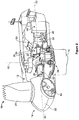
- Figure 2 is a partially cut-away perspective view of a portion of wind turbine 10.
- Wind turbine 10 described and shown herein is a wind turbine generator for generating electrical power from wind energy.
- wind turbine 10 described and illustrated herein includes a horizontal-axis configuration, however, in some embodiments, wind turbine 10 may include, in addition or alternative to the horizontal-axis configuration, a vertical-axis configuration (not shown).
- Wind turbine 10 may be coupled to an electrical load (not shown in Figure 1 ), such as, but not limited to, a power grid, for receiving electrical power therefrom to drive operation of wind turbine 10 and/or its associated components and/or for supplying electrical power generated by wind turbine 10 thereto. Although only one wind turbine 10 is shown in Figures 1 and 2 , in some embodiments, a plurality of wind turbines 10 may be grouped together, sometimes referred to as a "wind farm.”
- Wind turbine 10 includes a body or nacelle 12 and a rotor (generally designated by 14) coupled to nacelle 12 for rotation with respect to nacelle 12 about an axis of rotation 20.
- nacelle 12 is mounted on a tower 16, however, in some embodiments, in addition or alternative to tower-mounted nacelle 12, nacelle 12 may be positioned adjacent the ground and/or a surface of water.
- the height of tower 16 may be any suitable height enabling wind turbine 10 to function as described herein.
- Rotor 14 includes a hub 22 and a plurality of blades 24 (sometimes referred to as "airfoils”) extending radially outwardly from hub 22 for converting wind energy into rotational energy.
- Blades 24 may each have any length that allows wind turbine 10 to function as described herein.
- one or more rotor blades 24 are about one-half meter long, while in some embodiments one or more rotor blades 24 are about fifty meters long.
- Other examples of blade 24 lengths include ten meters or less, about twenty meters, about thirty-seven meters, and about forty meters.
- Still other examples include rotor blades between about fifty and about one-hundred meters long, and rotor blades greater than one-hundred meters long.
- rotor 14 may have blades 24 of any shape, and may have blades 24 of any type and/or any configuration, whether such shape, type, and/or configuration is described and/or illustrated herein.
- One example of another type, shape, and/or configuration of blades 24 is a Darrieus wind turbine, sometimes referred to as an "eggbeater" turbine.
- Yet another example of another type, shape, and/or configuration of blades 24 is a Savonious wind turbine.
- wind turbine 10 may, in some embodiments, be a wind turbine wherein rotor 14 generally faces upwind to harness wind energy, and/or may be a wind turbine wherein rotor 14 generally faces downwind to harness energy.
- rotor 14 may not face exactly upwind and/or downwind, but may face generally at any angle (which may be variable) with respect to a direction of the wind to harness energy therefrom.
- wind turbine 10 includes an electrical generator 26 coupled to rotor 14 for generating electrical power from the rotational energy generated by rotor 14.
- Generator 26 may be any suitable type of electrical generator, such as, but not limited to, a wound rotor induction generator, a double-fed induction generator (DFIG, also known as dual-fed asynchronous generators), a permanent magnet (PM) synchronous generator, an electrically-excited synchronous generator, and a switched reluctance generator.
- Generator 26 includes a stator (not shown) and a rotor (not shown) with an air gap included therebetween.
- Rotor 14 includes a rotor shaft 28 coupled to rotor hub 22 for rotation therewith.
- Generator 26 is coupled to rotor shaft 28 such that rotation of rotor shaft 28 drives rotation of the generator rotor, and therefore operation of generator 26.
- the generator rotor has a generator shaft 30 coupled thereto and coupled to rotor shaft 28 such that rotation of rotor shaft 28 drives rotation of the generator rotor.
- the generator rotor is directly coupled to rotor shaft 28, sometimes referred to as a "direct-drive wind turbine.”
- generator shaft 30 is coupled to rotor shaft 28 through a gearbox 32, although in other embodiments generator shaft 30 is coupled directly to rotor shaft 28.
- the torque of rotor 14 drives the generator rotor to thereby generate variable frequency AC electrical power from rotation of rotor 14.
- Generator 26 has an air gap torque between the generator rotor and stator that opposes the torque of rotor 14.
- a power conversion assembly 34 is coupled to generator 26 for converting the variable frequency AC to a fixed frequency AC for delivery to an electrical load (not shown in Figure 2 ), such as, but not limited to a power grid (not shown in Figure 2 ), coupled to generator 26.
- Power conversion assembly 34 may include a single frequency converter or a plurality of frequency converters configured to convert electricity generated by generator 26 to electricity suitable for delivery over the power grid.
- Power conversion assembly 34 may also be referred to herein as a power converter.
- Power conversion assembly 34 may be located anywhere within or remote to wind turbine 10. For example, power conversion assembly 34 may be located within a base (not shown) of tower 16.
- wind turbine 10 may include a rotor speed limiter, for example, but not limited to a disk brake 36.
- Disk brake 36 brakes rotation of rotor 14 to, for example, slow rotation of rotor 14, brake rotor 14 against full wind torque, and/or reduce the generation of electrical power from electrical generator 26.
- wind turbine 10 may include a yaw system 38 for rotating nacelle 12 about an axis of rotation 40 for changing a yaw of rotor 14, and more specifically for changing a direction faced by rotor 14 to, for example, adjust an angle between the direction faced by rotor 14 and a direction of wind.
- wind turbine 10 includes a variable blade pitch system 42 for controlling, including but not limited to changing, a pitch angle of blades 24 (shown in Figures 1-2 ) with respect to a wind direction.
- Pitch system 42 may be coupled to system controller 44 for control thereby.
- Pitch system 42 is coupled to hub 22 and blades 24 for changing the pitch angle of blades 24 by rotating blades 24 with respect to hub 22.
- the pitch actuators may include any suitable structure, configuration, arrangement, means, and/or components, whether described and/or shown herein, such as, but not limited to, electrical motors, hydraulic cylinders, springs, and/or servomechanisms.
- the pitch actuators may be driven by any suitable means, whether described and/or shown herein, such as, but not limited to, hydraulic fluid, electrical power, electro-chemical power, and/or mechanical power, such as, but not limited to, spring force.
- FIG 3 is a block diagram of an exemplary embodiment of wind turbine 10.
- wind turbine 10 includes one or more system controllers 44 coupled to at least one component of wind turbine 10 for generally controlling operation of wind turbine 10 and/or controlling operation of the components thereof, regardless of whether such components are described and/or shown herein.
- system controller 44 is coupled to pitch system 42 for generally controlling rotor 14.
- system controller 44 is mounted within nacelle 12 (shown in Figure 2 ), however, additionally or alternatively, one or more system controllers 44 may be remote from nacelle 12 and/or other components of wind turbine 10.
- System controllers 44 may be used for overall system monitoring and control including, without limitation, pitch and speed regulation, high-speed shaft and yaw brake application, yaw and pump motor application, and/or fault monitoring.
- Alternative distributed or centralized control architectures may be used in some embodiments.
- wind turbine 10 includes a plurality of sensors, for example, sensors 50, 54, and 56.
- Sensors 50, 54, and 56 measure a variety of parameters including, without limitation, operating conditions and atmospheric conditions.
- Each sensor 50, 54, and 56 may be an individual sensor or may include a plurality of sensors.
- Sensors 50, 54, and 56 may be any suitable sensor having any suitable location within or remote to wind turbine 10 that allows wind turbine 10 to function as described herein.
- sensors 50, 54, and 56 are coupled to system controller 44 for transmitting measurements to system controller 44 for processing thereof.
- system controller 44 includes a bus 62 or other communications device to communicate information.
- processor(s) 64 are coupled to bus 62 to process information, including information from sensors 50, 54, and 56 and/or other sensor(s).
- Processor(s) 64 may include at least one computer.
- the term computer is not limited to integrated circuits referred to in the art as a computer, but broadly refers to a processor, a microcontroller, a microcomputer, a programmable logic controller (PLC), an application specific integrated circuit, and other programmable circuits, and these terms are used interchangeably herein.
- System controller 44 may also include one or more random access memories (RAM) 66 and/or other storage device(s) 68.
- RAM(s) 66 and storage device(s) 68 are coupled to bus 62 to store and transfer information and instructions to be executed by processor(s) 64.
- RAM(s) 66 (and/or storage device(s) 68, if included) can also be used to store temporary variables or other intermediate information during execution of instructions by processor(s) 64.
- System controller 44 may also include one or more read only memories (ROM) 70 and/or other static storage devices coupled to bus 62 to store and provide static (i.e., non-changing) information and instructions to processor(s) 64.
- ROM read only memories
- Processor(s) 64 process information transmitted from a plurality of electrical and electronic devices that may include, without limitation, speed and power transducers. Instructions that are executed include, without limitation, resident conversion and/or comparator algorithms. The execution of sequences of instructions is not limited to any specific combination of hardware circuitry and software instructions.
- System controller 44 may also include, or may be coupled to, input/output device(s) 72.
- Input/output device(s) 72 may include any device known in the art to provide input data to system controller 44 and/or to provide outputs, such as, but not limited to, yaw control and/or pitch control outputs.
- Instructions may be provided to RAM 66 from storage device 68 including, for example, a magnetic disk, a read-only memory (ROM) integrated circuit, CD-ROM, and/or DVD, via a remote connection that is either wired or wireless providing access to one or more electronically-accessible media.
- ROM read-only memory
- DVD digital versatile discs
- hard-wired circuitry can be used in place of or in combination with software instructions.
- input/output device(s) 72 may include, without limitation, computer peripherals associated with an operator interface such as a mouse and a keyboard (neither shown in Figure 3 ). Alternatively, other computer peripherals may also be used that may include, for example, a scanner (not shown in Figure 3 ). Furthermore, in the exemplary embodiment, additional output channels may include, for example, an operator interface monitor (not shown in Figure 3 ).
- System controller 44 may also include a sensor interface 74 that allows system controller 44 to communicate with sensors 50, 54, and 56 and/or other sensor(s). Sensor interface 74 may include one or more analog-to-digital converters that convert analog signals into digital signals that can be used by processor(s) 64.
- wind turbine 10 includes a phase locked loop (PLL) regulator 80.
- PLL regulator 80 is coupled to sensor 54.
- sensor 54 is a voltage transducer configured to measure a terminal grid voltage output by frequency converter 34.
- PLL regulator 80 is configured to receive a plurality of voltage measurement signals from a plurality of voltage transducers.
- each of three voltage transducers is electrically coupled to each one of three phases of a grid bus.
- PLL regulator 80 may be configured to receive any number of voltage measurement signals from any number of voltage transducers that allow PLL regulator 80 to function as described herein.
- FIG 4 is a block diagram of an exemplary power generation and delivery system 150.
- Power generation and delivery system 150 may be used with, or included within, wind turbine 10 (shown in Figures 1 and 2 ).
- System 150 includes an energy source, for example, generator 26. Although described herein as wind turbine generator 26, the energy source may include any type of electrical generator that allows system 150 to function as described herein.
- System 150 also includes a power converter, such as, power converter 34.
- Power converter 34 receives variable frequency electrical power 132 generated by generator 26 and converts electrical power 132 to an electrical power 134 (referred to herein as terminal power 134) suitable for transmission over an electric power transmission and distribution grid 136 (referred to herein as utility grid 136).
- a terminal voltage (Vt) 138 is defined at a node between power converter 34 and utility grid 136.
- a load 140 is coupled to utility grid 136 where a Thevenin voltage is defined.
- variable speed operation of wind turbine 10 facilitates enhanced capture of energy when compared to a constant speed operation of wind turbine 10, however, variable speed operation of wind turbine 10 produces electrical power 132 having varying voltage and/or frequency. More specifically, the frequency of electrical power 132 generated by variable speed wind turbine generator 26 is proportional to the speed of rotation of rotor 14 (shown in Figure 1 ).
- power converter 34 outputs terminal power 134 having a substantially fixed voltage and frequency for delivery on utility grid 136.
- Power converter 34 also controls an air gap torque of generator 26.
- the air gap torque is present between the generator rotor (not shown in Figure 3 ) and the generator stator (not shown in Figure 3 ) and opposes the torque applied to generator 26 by rotor 14.
- a balance between a torque on rotor 14 created by interaction of blades 24 (shown in Figure 1 ) and the wind and the air gap torque facilitates stable operation of wind turbine 10.
- Wind turbine adjustments, for example, blade pitch adjustments, or grid events, for example, low voltage transients or zero voltage transients on utility grid 136, may cause an imbalance between the torque on rotor 14 caused by the wind and the air gap torque.
- Power converter 34 controls the air gap torque which facilitates controlling the power output of generator 26, however, wind turbine 10 may not be able to operate through certain grid events, or may sustain wear and/or damage due to certain grid events, due to a time period required for adjustments to wind turbine operation to take effect after detecting the grid event.
- system 150 includes a grid-dependent power limiter system 152.
- a controller for example, but not limited to, controller 44 (shown in Figure 3 ), is programmed to perform the functions of grid-dependent power limiter system 152.
- the functions of grid-dependent power limiter system 152 may be performed by any circuitry configured to allow system 150 to function as described herein.
- Power limiter system 152 is configured to identify the occurrence of a grid contingency event, and provide power converter 34 with signals that facilitate reducing pole-slipping and providing a stable recovery from the grid event.
- power converter 34 responds according to the signals provided by power limiter system 152 and substantially eliminates pole-slipping.
- a grid event also referred to herein as a grid contingency event, may leave utility grid 136 in a degraded mode where the grid impedance is too high to accommodate power generated by generator 26.
- An example of a grid event includes a short-circuit fault on one of the transmission lines within utility grid 136. Electrical transmission protection actions remove the faulted portion of utility grid 136 to permit operation of the remaining unfaulted portion of utility grid 136. A transmission path remains that is degraded in its ability to transmit power from system 150 to load 140. Such grid events cause a brief period of low voltage on utility grid 136 prior to clearing the faulted portion of the utility grid 136. Typically, terminal voltage 138 will approach zero volts at the time of the grid event.
- System 150 facilitates low voltage ride through capability (LVRT) as well as zero voltage ride through (ZVRT) capability for wind turbine 10 such that a potential for a wind turbine generator trip and associated consequences to the semiconductor devices are mitigated during low voltage transients and/or zero voltage transients.
- LVRT low voltage ride through capability
- ZVRT zero voltage ride through
- Such a grid event may lead to a post-fault condition where the high impedance of utility grid 136 prevents utility grid 136 from transmitting the pre-fault power from wind generator 26 (i.e., the impedance of utility grid 136 is too high to carry the pre-fault power from wind generator 26).
- this condition may cause a rotor angle of the generator rotor to move past the point where a restraining torque of utility grid 136 is able to balance the mechanical input to wind turbine 10, which is referred to herein as "pole-slipping.”
- this condition may lead to a series of rapid pulsations of power and voltage.
- Such pulsations are analogous to pole-slipping, although with power converter 34, control algorithms govern the behavior rather than the physics of synchronous machines. Without precautions in the power converter control algorithms, pole-slipping may occur.
- the methods and systems described herein facilitate preventing the pulsating pole-slipping and facilitate stabilizing system 150 upon detection of pole-slipping in a short period of time such that higher-level controls have time to determine actions and communicate those actions to bring the system to an acceptable condition.
- power conversion assembly 34 is configured to receive control signals 154 from a converter interface controller 156.
- Control signals 154 are based on sensed operating conditions or operating characteristics of wind turbine 10 as described herein and used to control the operation of power conversion assembly 34. Examples of measured operating conditions may include, but are not limited to, a terminal grid voltage, a PLL error, a stator bus voltage, a rotor bus voltage, and/or a current.
- sensor 54 measures terminal grid voltage 138 and transmits a terminal grid voltage feedback signal 160 to power limiter system 152.
- Power limiter system 152 generates a power command signal 162 based at least partially on the feedback signal 160 and transmits power command signal 162 to converter interface controller 156.
- converter interface controller 156 is included within system controller 44.
- Other operating condition feedback from other sensors also may be used by controller 44 and/or converter interface controller 156 to control power conversion assembly 34.
- switching control signals, stator synchronizing switch control signals and system circuit breaker control (trip) signals may be generated in any known manner.
- controller 44 and/or converter interface controller 156 will at least temporarily substantially suspend firing of the IGBTs within power conversion assembly 34. Such suspension of operation will substantially mitigate electric power being channeled through power conversion assembly 34 to approximately zero.
- FIG. 5 is a block diagram of an exemplary power limiter system, for example, power limiter system 152.
- Power limiter system 152 is configured to output power command signal 162 (shown in Figure 4 ), which in the exemplary embodiment, is at least one of a real current command signal 166 and a reactive current command signal 168.
- power limiter system 152 includes a power limiter 180, a power regulator 182, and a voltage regulator 184.
- power limiter 180 receives at least one measured operating condition of system 150.
- the at least one measured operating condition may include, but is not limited to, a PLL error signal 190 from PLL regulator 80 and terminal grid voltage feedback signal 160 from sensor 54.
- Power limiter 180 also receives a stored reference power control signal 194 from, for example, system controller 44 (shown in Figure 3 ). In some embodiments, power limiter 180 receives terminal grid voltage feedback signal 160 and stored reference power control signal 194. In other embodiments, power limiter 180 receives PLL error signal 190 and stored reference power control signal 194. In other embodiments, power limiter 180 receives both PLL error signal 190 and terminal grid voltage feedback signal 160, as well as stored reference power control signal 194. In the exemplary embodiment, power limiter 180 generates a power command signal 198 and transmits power command signal 198 to power regulator 182. Power regulator 182 generates real current command signal 166 and transmits real current command signal 166 to converter interface controller 156. Converter interface controller 156 may also be referred to herein as a converter firing control. As described above, PLL regulator 80 may be included within system controller 44, or may be coupled to, but separate from, system controller 44.
- PLL regulator 80 receives terminal voltage feedback signal 160.
- PLL regulator 80 may receive terminal voltage feedback signal 160 (shown in Figure 3 as Vt) provided by sensor 54 (shown in Figure 3 ).
- PLL regulator 80 generates PLL error signal 190 and a PLL phase angle signal 202.
- PLL phase angle signal 202 is transmitted to converter interface controller 156 for control of assembly 34 and for subsequent control of electrical currents injected onto utility grid 136 (shown in Figure 4 ).
- FIG. 6 is a block diagram of an exemplary grid-dependent power limiter, for example, power limiter 180 (shown in Figure 5 ).
- a grid contingency such as a weak grid
- the impedance of utility grid 136 is too high to accommodate the power generated by generator 26.
- pole-slipping may occur causing repetitive voltage depressions and power pulsations on utility grid 136 and wind turbine 10.
- the weak grid causes a reduction in the Thevenin equivalent voltage at load 140 on utility grid 136.
- a power command to converter interface controller 156 is rapidly reduced. More specifically, real current command signal 166 is generated by power regulator 182 and transmitted to converter interface controller 156.
- Real current command signal 166 instructs converter interface controller 156 to decrease a real component of current that conversion assembly 34 tries to inject onto utility grid 136. Furthermore, to support the terminal voltage, upon a drop in terminal voltage identified by voltage regulator 184 based on terminal voltage feedback signal 160, voltage regulator 184 generates reactive current command signal 168 and sends reactive current command signal 168 to converter interface controller 156. Current command signal 168 instructs converter interface controller 156 to increase a reactive component of current injected onto utility grid 136 upon occurrence of a grid contingency event.
- power regulator 182 receives power command signal 198 from power limiter 180.
- Power command signal 198 provides power regulator 182 with a signal corresponding to an occurrence of a grid contingency event.
- a low terminal voltage is an indication that a grid contingency event has occurred.
- a high PLL error is an indication that a grid contingency event has occurred.
- a function block 220 within power limiter 180 receives terminal voltage feedback signal 160 and/or PLL error signal 190.
- a power limit function block 222 generates a power limit control signal 224 based on an output 226 of function block 220.
- Power limit control signal 224 and reference power control signal 194 are provided to a comparator function block 230.
- Comparator function block 230 generates power command signal 198 corresponding to the lesser of power limit control signal 224 and reference power control signal 194.
- terminal voltage feedback signal 160 indicates a sudden reduction in the terminal voltage.
- power limit function block 222 generates a rapidly reducing power limit control signal 224. Rapidly reducing power limit control signal 224 facilitates stabilizing system 150 while substantially reducing pole-slipping.
- power limit function block 222 After terminal voltage feedback signal 160 indicates that the grid contingency event has ended (e.g., the terminal voltage increases), power limit function block 222 generates a slowly rising power limit control signal 224.
- the real current injected onto utility grid 136 rises according to power limit control signal 224.
- Slowly increasing the power injected onto utility grid 136 facilitates preventing power oscillations.
- slowly increasing the power injected onto utility grid 136 provides time for higher level changes in the operation of system 150 that allow system 150 to adapt to the grid contingency event.
- power limit control signal 224 is compared to reference power control signal 194.
- Comparator function block 230 generates power command signal 198 based on the lower of power limit control signal 224 and reference power control signal 194.
- power limit control signal 224 is lower than reference power control signal 194 after occurrence of a grid contingency event, and as such, power command signal 198 is generated based on power limit control signal 224.
- reference power control signal 194 is less than power limit control signal 224, and power command signal 198 is based on the predetermined reference power control signal 194.
- PLL error signal 190 and terminal voltage feedback signal 160 are both indicators of the occurrence of a grid contingency event.
- a PLL error signal 190 that corresponds to a high PLL error and a terminal voltage feedback signal 160 that corresponds to a reduction in terminal voltage 138 are indications that a grid contingency event has occurred.
- power limit function block 222 In response to a high PLL error signal 190 and/or a low terminal voltage feedback signal 160, power limit function block 222 generates a rapidly reducing power limit control signal 224.
- power limit function block 222 After PLL error signal 190 and/or terminal voltage feedback signal 160 indicate that the grid contingency event has ended (e.g., the PLL error and/or the terminal voltage returns to a predefined level), power limit function block 222 generates a slowly rising power limit control signal 224. The power injected onto utility grid 136 rises according to power limit control signal 224. As described above, slowly increasing the power injected onto utility grid 136 facilitates preventing power oscillations.
- power limiter 180 also includes a higher-level control 232. Although described as included within power limiter 180, higher-level control 232 may also be positioned remotely from power limiter 180. As described above, slowly increasing the power injected onto utility grid 136 facilitates preventing power oscillations. Slowly increasing the power injected onto utility grid 136 also provides time for higher level changes in the operation of system 150 that allow system 150 to adapt to the grid contingency event.
- Higher-level control 232 receives at least one wind farm input signal, for example, input signal 234. Wind farm input signal 234 may correspond to changes in utility grid 136, for example, but not limited to, breaker contact signals or communication signals from remote substations.
- Input signal 234 may also correspond to a voltage measurement at a point of common coupling for a plurality of wind turbines within a wind farm.
- higher-level control 232 generates a curtailment signal 236 based at least partially on input signal 234, and provides curtailment signal 236 to select wind turbines of the plurality of wind turbines. More specifically, curtailment signal 236 is provided to comparator function block 230, where power command signal 198 is generated.
- higher-level control 232 will generate curtailment signal 236, which upon receipt, instructs comparator function block 230 to generate a power command signal 198 that curtails a wind turbine's output below that which would otherwise be available from the prevailing wind conditions.
- higher-level control 232 determines that the voltage at the point of common coupling for a plurality of wind turbines has remained below a predefined level for more than a predefined period of time, higher-level control 232 will generate curtailment signal 236, which upon receipt, instructs comparator function block 230 to generate a power command signal 198 that curtails a wind turbine's output below that which would otherwise be available from the prevailing wind conditions.
- power limiter system 152 also includes a memory, for example, memory 66 (shown in Figure 3 ).
- Memory 66 is configured to store data related to operation of wind turbine 10.
- memory 66 may store at least one variable that correspond to, for example but not limited to, PLL error 190 and voltage feedback 160.
- controller 44 is configured to sample the current value of predefined variables and store the current value in memory 66 upon occurrence of an event. For example, upon occurrence of a grid contingency event, current values for PLL error 190 and voltage feedback 160 are stored in memory 66.
- Memory 66 may be accessed by a user to, for example, monitor operation of wind turbine 10.
- Figure 7 is a graphical view of grid line voltage versus time that may be associated with wind turbine 10 (shown in Figure 1 ).
- Graph 240 includes an ordinate (y-axis) 242 that represents grid line voltage in units of percent (%). Y-axis 242 illustrates 0% at the graph origin and extends up to 100%.
- a grid line voltage of 0% is indicative of zero voltage on utility grid 136 (shown in Figure 4 ).
- a grid line voltage of 100% indicates terminal grid voltage 138 is 100% of the nominal pre-determined voltage associated with wind turbine 10.
- Graph 240 also includes an abscissa (x-axis) 244 that represents time in seconds (s). A zero voltage transient is illustrated to start at time equals zero seconds.
- This zero voltage transient may correspond to a grid event, for example, a de-coupled load that causes a zero voltage grid condition.
- the zero voltage condition on utility grid 136 is 0.15 seconds wherein the voltage on utility grid 136 fully recovers to 100% at approximately 3.5 seconds after the initiation of the transient.
- a length of time of the zero voltage condition and the characteristics of a grid voltage recovery depend upon a variety of factors known in the art.
- Figures 8-15 show operating characteristics of system 150 (shown in Figure 4 ) after occurrence of a grid contingency event.
- system 150 includes power limiter system 152 (shown in Figure 5 ). More specifically, Figures 8-11 show exemplary operating characteristics of system 150 when power limiter 180 of power limiter system 152 is provided with terminal voltage feedback signal 160 (shown in Figure 5 ). Figures 12-15 show exemplary operating characteristics of system 150 when power limiter 180 is provided with PLL error signal 190.
- Figures 8-11 show an effect of a grid contingency event on system 150 (shown in Figure 4 ) when power limiter 180 is provided with terminal voltage feedback signal 160.
- Figure 8 shows an effect of a grid contingency event on terminal grid voltage 138 (shown in Figure 4 ) over time 610.
- Figure 9 shows an effect of a grid contingency event on terminal power 134 (shown in Figure 4 ) over time 610.
- Figure 10 shows an effect of a grid contingency event on power limit control signal 224 (shown in Figure 6 ) and reference power control signal 194 (shown in Figure 6 ) over time 610.
- Figure 11 shows an effect of a grid contingency event on PLL error signal 190 (shown in Figure 6 ).
- power limit control signal 224 is rapidly reduced to below a level of reference power control signal 194. Reducing power limit control signal 224 causes power converter 34 to reduce a level of real current applied to utility grid 136, and as shown in Figures 8-11 , facilitates stabilizing system 150 (i.e., reduces oscillations of Vt, Pt, and PLL error).
- Figures 12-15 shows an effect of a grid contingency event on system 150 (shown in Figure 4 ) when power limiter 180 is provided with PLL error signal 190.
- Figure 12 shows an effect of a grid contingency event on terminal grid voltage 138 (shown in Figure 4 ) over time 610.
- Figure 13 shows an effect of a grid contingency event on terminal power 134 (shown in Figure 4 ) over time 610.
- Figure 14 shows an effect of a grid contingency event on power limit control signal 224 (shown in Figure 6 ) and reference power control signal 194 (shown in Figure 6 ) over time 610.
- Figure 15 shows an effect of a grid contingency event on PLL error signal 190 (shown in Figure 6 ).
- power limit control signal 224 is rapidly reduced to below a level of reference power control signal 194. Reducing power limit control signal 224 causes power converter 34 to reduce a level of real current applied to utility grid 136, and as shown in Figures 12-15 , facilitates stabilizing system 150 (i.e., reduces oscillations of Vt, Pt, and PLL error).
- Figure 16 is a flow chart 260 illustrating an exemplary method for controlling operation of a wind turbine, for example, wind turbine 10 (shown in Figure 1 ), included within a power generation and delivery system, for example, power generation and delivery system 150 (shown in Figure 4 ).
- a wind turbine for example, wind turbine 10 (shown in Figure 1 )
- the method may also be applied to operation of more than one wind turbine 10 (i.e., a wind farm).
- the method includes measuring 270 at least one operating condition of power generation and delivery system 150, wherein the at least one operating condition is dependent upon an occurrence of a grid contingency event.
- measured operating conditions provide an indication of an occurrence of a grid contingency event.
- the measured operating condition may include, but is not limited to, at least one of a phase locked loop (PLL) error and a terminal grid voltage.
- the method also includes transmitting 272, to a power limiter system, an operating condition feedback signal that corresponds to the at least one operating condition.
- PLL error signal 190 (shown in Figure 5 ) may be generated by a PLL regulator, for example, PLL regulator 80 (shown in Figure 5 ) and transmitted 272 to power limiter system 152 (shown in Figure 5 ).
- PLL error signal 190 may correspond to a sustained phase error tracked by PLL regulator 80.
- terminal grid voltage feedback signal 160 (shown in Figure 5 ) may be measured by sensor 54 (shown in Figure 3 ) and transmitted 272 to power limiter system 152.
- the method also includes analyzing 274, using power limiter system 152, the operating condition feedback signal to identify an occurrence of a grid contingency event.
- an increasing PLL error signal 190 provides an indication that a grid contingency event is occurring and/or a rapidly decreasing terminal grid voltage 138 provides an indication that a grid contingency event is occurring.
- the method also includes generating 278, using power limiter system 152, a real current command signal corresponding to an occurrence of a grid contingency event.
- a real current command signal such as real current command signal 166 (shown in Figure 5 ) is generated by power limiter system 152.
- Real current command signal 166 may be based at least partially on the terminal grid voltage and is used as an indicator of an occurrence of a grid contingency event. For example, a real current command signal 166 is generated that corresponds to an occurrence of a grid contingency event when terminal grid voltage 138 is below a predefined level.
- Real current command signal 166 may also be based at least partially on PLL error signal 190. For example, a real current command signal 166 that corresponds to an occurrence of a grid contingency event is generated when PLL error signal 190 is above a predefined level.
- Real current command signal 166 may also be based on both terminal grid voltage 138 and PLL error signal 190. In this alternative embodiment, if terminal grid voltage 138 and/or PLL error signal 190 indicate the occurrence of a grid contingency event, power limiter system 152 outputs a real current command signal 166 that corresponds to an occurrence of a grid contingency event.
- the method also includes transmitting 280 real current command signal 166 to a controller, for example, converter interface controller 156 (shown in Figure 5 ) and applying 282 real current command signal 166 to performance of a power converter, for example, power conversion assembly 34 (shown in Figure 3 ).
- a controller for example, converter interface controller 156 (shown in Figure 5 )
- 282 real current command signal 166 to performance of a power converter, for example, power conversion assembly 34 (shown in Figure 3 ).
- power conversion assembly 34 Upon receipt of real current command signal 166 that corresponds to an occurrence of a grid contingency event, power conversion assembly 34 rapidly reduces a real current output.
- power conversion assembly 34 slowly increases real current output by power conversion assembly 34 to facilitate a stable recovery from the grid contingency event and substantially eliminate pole-slipping.
- the method also includes storing 284, in a memory, at least one variable corresponding to the at least one operating condition upon the occurrence of a grid contingency event.
- variables corresponding to the at least one operating condition may be stored 284 in memory 66 (shown in Figure 3 ).
- Memory 66 may store a plurality of variables that correspond to, for example but not limited to, PLL error 190 and voltage feedback 160.
- controller 44 is configured to sample the current value of predefined variables and store the current value in memory 66 upon occurrence of an event.
- current values for PLL error 190 and voltage feedback 160 are stored in memory 66.
- Memory 66 may be accessed by a user to, for example, monitor operation of wind turbine 10 and/or verify proper operation of wind turbine 10, power limiter system 152, and/or power generation and delivery system 150.
- the method may also include transmitting 290 terminal grid voltage 138 to a voltage regulator, for example, voltage regulator 184 (shown in Figure 5 ) and generating 292 a reactive current command signal, for example, reactive current command signal 168, at voltage regulator 184 that increases the reactive current output by power conversion assembly 34 when terminal grid voltage 138 indicates the occurrence of a grid contingency event.
- a voltage regulator for example, voltage regulator 184 (shown in Figure 5 ) and generating 292 a reactive current command signal, for example, reactive current command signal 168, at voltage regulator 184 that increases the reactive current output by power conversion assembly 34 when terminal grid voltage 138 indicates the occurrence of a grid contingency event.
- the increased reactive current supports terminal grid voltage 138 until the grid contingency event is resolved or higher-level control of wind turbine 10 operation is activated.
- a higher-level control for example, higher-level control 232 (shown in Figure 6 ), receives a wind farm operating condition, generates a curtailment signal based at least partially on the wind farm operating condition, and transmits the curtailment signal to power limiter system 152.
- the above-described embodiments facilitate efficient and cost-effective operation of a wind turbine.
- the wind turbine includes a power limiter system that is provided with at least one of a terminal voltage feedback signal and a PLL error signal.
- the terminal voltage feedback signal and the PLL error signal facilitate identification of a grid contingency event and signals provided by the methods and systems described herein facilitate rapid response to an identified grid contingency event.
- a rapid reduction in real current applied to the utility grid after identification of a grid contingency event substantially eliminates pole-slipping.
- a slow increase in real current applied to the utility grid upon recovery of the utility grid provides time for higher-level control systems to balance the power generated by the wind turbine, or by wind turbines within a wind farm, with a load level on the utility grid.
- the method and systems described herein facilitate achieving zero and low voltage ride through which may prevent a generator trip and/or support the grid during the voltage transient.
- Exemplary embodiments of a wind turbine, power limiter system, and methods for operating a wind turbine in response to an occurrence of a grid contingency event are described above in detail.
- the methods, wind turbine, and power limiter system are not limited to the specific embodiments described herein, but rather, components of the wind turbine, components of the power limiter system, and/or steps of the methods may be utilized independently and separately from other components and/or steps described herein.
- the power limiter system and methods may also be used in combination with other wind turbine power systems and methods, and are not limited to practice with only the power system as described herein. Rather, the exemplary embodiment can be implemented and utilized in connection with many other wind turbine or power system applications.
Claims (6)
- Système limiteur de puissance fonction du réseau (152) pour réduire un glissement de pôle, ledit système comprenant :un limiteur de puissance (180) configuré pour :recevoir un signal d'erreur à boucle verrouillée en phase (190) et un signal de rétroaction de tension terminale de réseau (160) ;générer un signal de commande de puissance (198) sur la base du signal d'erreur à boucle verrouillée en phase et du signal de rétroaction de tension terminale de réseau ;un régulateur de puissance (182) couplé audit limiteur de puissance, ledit régulateur de puissance étant configuré pour :recevoir le signal de commande de puissance ;générer un signal de commande de courant réel (166) sur la base au moins en partie du signal de commande de puissance ; ettransmettre le signal de commande de courant réel à un dispositif de commande (156).
- Système (152) selon la revendication 1, comprenant en outre un régulateur de tension (184) configuré pour :recevoir le signal de rétroaction de tension terminale de réseau (160) ;générer un signal de commande de courant réactif (168) sur la base au moins en partie du signal de rétroaction de tension terminale de réseau ; ettransmettre le signal de commande de courant réactif au dispositif de commande (156).
- Système (152) selon l'une quelconque des revendications précédentes, dans lequel le limiteur de puissance (180) est configuré pour générer un signal de commande de puissance (198) qui correspond à un événement de contingence de réseau lorsque le signal de rétroaction de tension terminale de réseau (160) indique que la tension terminale de réseau (138) se situe en dessous d'un niveau prédéfini.
- Système (152) selon l'une quelconque des revendications précédentes, dans lequel le limiteur de puissance (180) est configuré pour générer un signal de commande de puissance (198) qui correspond à un événement de contingence de réseau lorsque le signal d'erreur PLL (190) se situe au-dessus d'un niveau prédéfini.
- Système (152) selon l'une quelconque des revendications précédentes, dans lequel le régulateur de puissance (182) est configuré pour générer un signal de commande de courant réel (166) qui dirige un convertisseur de puissance (34) pour réduire rapidement un courant réel délivré par le convertisseur de puissance après identification d'un événement de contingence de réseau.
- Système (152) selon l'une quelconque des revendications précédentes, dans lequel le régulateur de puissance (182) est configuré pour générer un signal de commande de courant réel (166) qui dirige le convertisseur de puissance (34) pour augmenter lentement le courant réel délivré par le convertisseur de puissance après une récupération d'un événement de contingence de réseau.
Applications Claiming Priority (1)
| Application Number | Priority Date | Filing Date | Title |
|---|---|---|---|
| US12/639,672 US8046109B2 (en) | 2009-12-16 | 2009-12-16 | Method and systems for operating a wind turbine |
Publications (3)
| Publication Number | Publication Date |
|---|---|
| EP2336554A2 EP2336554A2 (fr) | 2011-06-22 |
| EP2336554A3 EP2336554A3 (fr) | 2015-08-12 |
| EP2336554B1 true EP2336554B1 (fr) | 2017-09-27 |
Family
ID=43608629
Family Applications (1)
| Application Number | Title | Priority Date | Filing Date |
|---|---|---|---|
| EP10193906.4A Not-in-force EP2336554B1 (fr) | 2009-12-16 | 2010-12-07 | Systèmes de fonctionnement d'une éolienne |
Country Status (3)
| Country | Link |
|---|---|
| US (2) | US8046109B2 (fr) |
| EP (1) | EP2336554B1 (fr) |
| CN (1) | CN102104256B (fr) |
Families Citing this family (40)
| Publication number | Priority date | Publication date | Assignee | Title |
|---|---|---|---|---|
| DE102007021632A1 (de) * | 2007-05-09 | 2008-11-20 | Ssb-Antriebstechnik Gmbh & Co. Kg | Elektrischer Antrieb |
| DE102008007448A1 (de) * | 2008-02-01 | 2009-08-13 | Woodward Seg Gmbh & Co. Kg | Verfahren zum Betreiben einer Windenergieanlage |
| ES2561842T3 (es) * | 2009-06-29 | 2016-03-01 | Vestas Wind Systems A/S | Turbina eólica que proporciona soporte a la red de distribución |
| DE102009037238B3 (de) * | 2009-08-12 | 2010-12-09 | Repower Systems Ag | Windenergieanlage mit veränderbarer Drehzahlkennlinie |
| CN102822508B (zh) * | 2010-02-25 | 2015-07-15 | 维斯塔斯风力系统集团公司 | 采用微分极控制算法的风力涡轮机控制器 |
| JP5439340B2 (ja) * | 2010-10-29 | 2014-03-12 | 三菱重工業株式会社 | ウインドファームの制御装置、ウインドファーム、及びウインドファームの制御方法 |
| EP2458205B1 (fr) * | 2010-11-26 | 2016-10-19 | Siemens Aktiengesellschaft | Procédé et système permettant de contrôler le dispositif électrique d'une éolienne |
| US8704390B2 (en) * | 2010-12-07 | 2014-04-22 | Vestas Wind Systems A/S | Dynamic adjustment of power plant output based on electrical grid characteristics |
| EP2485358B2 (fr) * | 2011-02-07 | 2021-12-22 | Siemens Gamesa Renewable Energy A/S | Système et procédé pour atténuer un déséquilibre électrique d'un courant triphasé dans un point de couplage commun entre un parc éolien et un réseau électrique |
| WO2012153185A1 (fr) * | 2011-05-11 | 2012-11-15 | Condor Wind Energy Limited | Système de gestion de puissance |
| US8626063B2 (en) * | 2011-06-08 | 2014-01-07 | Vishal Malhan | Wireless telemetry auto tuning for torque measurement system |
| WO2012178176A1 (fr) * | 2011-06-23 | 2012-12-27 | Inventus Holdings, Llc | Génération électrique à multiples sites renouvelables et commande de puissance réactive |
| US9711964B2 (en) | 2011-09-26 | 2017-07-18 | General Electric Corporation | Method and system for operating a power generation and delivery system |
| US20130138257A1 (en) * | 2011-11-30 | 2013-05-30 | Thomas Edenfeld | System for operating an electric power system and method of operating the same |
| US9093928B2 (en) * | 2012-04-24 | 2015-07-28 | General Electric Company | Methods and systems for controlling a power converter |
| EP2859638B1 (fr) * | 2012-06-12 | 2020-05-06 | Vestas Wind Systems A/S | Commande de centrale éolienne en cas de défaillance basse tension du réseau |
| CN102877945B (zh) * | 2012-06-15 | 2014-07-16 | 广东电网公司电力科学研究院 | 基于解析法的燃气轮机及其联合循环的变工况分析方法 |
| US9379551B2 (en) * | 2012-08-10 | 2016-06-28 | General Electric Company | Methods and systems for controlling a power converter |
| US8664788B1 (en) * | 2012-09-07 | 2014-03-04 | General Electric Company | Method and systems for operating a wind turbine using dynamic braking in response to a grid event |
| US8987929B2 (en) * | 2012-11-01 | 2015-03-24 | General Electric Company | System and method for operating wind farm |
| US9671442B2 (en) * | 2012-11-30 | 2017-06-06 | General Electric Company | System and method for detecting a grid event |
| US8872372B2 (en) | 2012-11-30 | 2014-10-28 | General Electric Company | Method and systems for operating a wind turbine when recovering from a grid contingency event |
| DE102013207255A1 (de) * | 2013-04-22 | 2014-10-23 | Wobben Properties Gmbh | Verfahren zum Einspeisen elektrischer Leistung in ein elektrisches Versorgungsnetz |
| US9506832B2 (en) | 2013-11-08 | 2016-11-29 | Laurel Valley Power Company, Llc | Portable high speed balance machine |
| US9863400B2 (en) | 2013-12-11 | 2018-01-09 | General Electric Company | System and method for controlling a wind turbine system |
| US9641113B2 (en) * | 2014-02-28 | 2017-05-02 | General Electric Company | System and method for controlling a power generation system based on PLL errors |
| US9520819B2 (en) | 2014-02-28 | 2016-12-13 | General Electric Company | System and method for controlling a power generation system based on a detected islanding event |
| US9548690B2 (en) | 2014-02-28 | 2017-01-17 | General Electric Company | System and method for adjusting current regulator gains applied within a power generation system |
| US10156224B2 (en) * | 2015-03-13 | 2018-12-18 | General Electric Company | System and method for controlling a wind turbine |
| US9605653B2 (en) | 2015-05-26 | 2017-03-28 | General Electric Company | System and method for de-rating power of a wind turbine as a function of temperature |
| US10024305B2 (en) | 2015-11-10 | 2018-07-17 | General Electric Company | System and method for stabilizing a wind farm during one or more contingency events |
| JP6421134B2 (ja) * | 2016-01-29 | 2018-11-07 | 三菱重工業株式会社 | 風力発電装置及びその運転方法 |
| US10491038B2 (en) * | 2017-06-15 | 2019-11-26 | General Electric Company | Electrical power subsystems and methods for controlling same |
| US20190093632A1 (en) * | 2017-09-27 | 2019-03-28 | General Electric Company | Methods for adapting wind farms for grid compliance |
| US11031784B2 (en) * | 2018-02-15 | 2021-06-08 | General Electric Company | Reactive current margin regulator for power systems |
| US10305283B1 (en) | 2018-02-22 | 2019-05-28 | General Electric Company | Power angle feedforward signal for phase locked loop in wind turbine power systems |
| DE102018116445A1 (de) * | 2018-07-06 | 2020-01-09 | Wobben Properties Gmbh | Verfahren zum Erkennen niederfrequenter Schwingungen und Erfassungseinrichtung dafür |
| US10985611B2 (en) | 2019-04-10 | 2021-04-20 | General Electric Company | System and method for estimating grid strength |
| US10742149B1 (en) | 2019-04-22 | 2020-08-11 | General Electric Company | System and method for reactive power control of a wind turbine by varying switching frequency of rotor side converter |
| CN114576075B (zh) * | 2022-03-09 | 2023-04-11 | 清华大学 | 一种波浪发电装置的限幅保护方法、装置及电子设备 |
Family Cites Families (17)
| Publication number | Priority date | Publication date | Assignee | Title |
|---|---|---|---|---|
| US4229694A (en) * | 1978-08-07 | 1980-10-21 | Wilson Gerald L | Power angle relay to measure and respond to the power angle of a synchronous generator |
| US5239251A (en) | 1989-06-30 | 1993-08-24 | The State Of Oregon Acting By And Through The State Board Of Higher Education On Behalf Of Oregon State University | Brushless doubly-fed motor control system |
| US6583521B1 (en) | 2000-03-21 | 2003-06-24 | Martin Lagod | Energy management system which includes on-site energy supply |
| EP1410490B1 (fr) | 2001-07-23 | 2013-09-04 | Northern Power Systems Utility Scale, Inc. | Systeme de commande d'un convertisseur de courant et procede de commande du fonctionnement d'un convertisseur de puissance |
| US6850426B2 (en) | 2002-04-30 | 2005-02-01 | Honeywell International Inc. | Synchronous and bi-directional variable frequency power conversion systems |
| US6921985B2 (en) | 2003-01-24 | 2005-07-26 | General Electric Company | Low voltage ride through for wind turbine generators |
| US7233129B2 (en) * | 2003-05-07 | 2007-06-19 | Clipper Windpower Technology, Inc. | Generator with utility fault ride-through capability |
| US7289920B2 (en) * | 2003-06-26 | 2007-10-30 | General Electric Company | Method and apparatus for capture of grid characteristics corresponding to fluctuation events |
| US7427815B1 (en) | 2003-11-14 | 2008-09-23 | General Electric Company | Method, memory media and apparatus for detection of grid disconnect |
| US7333352B2 (en) | 2004-07-01 | 2008-02-19 | Northern Power Systems, Inc. | Frequency control and power balancing in disturbed power inverter system and method thereof |
| US7298059B2 (en) * | 2004-12-17 | 2007-11-20 | General Electric Company | System and method for operating a wind farm under high wind speed conditions |
| US7253537B2 (en) | 2005-12-08 | 2007-08-07 | General Electric Company | System and method of operating double fed induction generators |
| US7312537B1 (en) | 2006-06-19 | 2007-12-25 | General Electric Company | Methods and apparatus for supplying and/or absorbing reactive power |
| US7629705B2 (en) * | 2006-10-20 | 2009-12-08 | General Electric Company | Method and apparatus for operating electrical machines |
| US7417333B2 (en) * | 2006-11-02 | 2008-08-26 | General Electric Company | Methods and apparatus for controlling current in an electrical machine |
| CN101141111B (zh) * | 2007-09-07 | 2010-07-28 | 浙江大学 | 一种双馈异步风力发电机转子电流无延时控制方法 |
| US7966103B2 (en) * | 2007-12-28 | 2011-06-21 | Vestas Wind Systems A/S | Apparatus and method for operating a wind turbine under low utility grid voltage conditions |
-
2009
- 2009-12-16 US US12/639,672 patent/US8046109B2/en active Active
-
2010
- 2010-12-07 EP EP10193906.4A patent/EP2336554B1/fr not_active Not-in-force
- 2010-12-16 CN CN201010615600.0A patent/CN102104256B/zh active Active
-
2011
- 2011-09-22 US US13/239,647 patent/US8509958B2/en active Active
Non-Patent Citations (1)
| Title |
|---|
| None * |
Also Published As
| Publication number | Publication date |
|---|---|
| US8509958B2 (en) | 2013-08-13 |
| US8046109B2 (en) | 2011-10-25 |
| CN102104256B (zh) | 2016-01-13 |
| US20120010759A1 (en) | 2012-01-12 |
| US20110137474A1 (en) | 2011-06-09 |
| EP2336554A2 (fr) | 2011-06-22 |
| EP2336554A3 (fr) | 2015-08-12 |
| CN102104256A (zh) | 2011-06-22 |
Similar Documents
| Publication | Publication Date | Title |
|---|---|---|
| EP2336554B1 (fr) | Systèmes de fonctionnement d'une éolienne | |
| EP2738904B1 (fr) | Procédé et systèmes permettant de faire fonctionner une éolienne lors de la récupération après un événement de défaillance du réseau | |
| EP2658112B1 (fr) | Procédés et systèmes permettant de commander un convertisseur de puissance | |
| EP2573894B1 (fr) | Procédé et systèmes permettant de faire fonctionner un système de génération et de distribution de puissance | |
| US20110142634A1 (en) | Overspeed protection system and method | |
| AU2013209323B2 (en) | Methods and systems for controlling a power converter | |
| CN111936740B (zh) | 用于功率系统的无功电流裕度调节器 | |
| EP2687857B1 (fr) | Procédés et systèmes destinés à être utilisés dans la surveillance d'un tachymètre d'une éolienne | |
| CN111712634B (zh) | 用于风力涡轮功率系统中的锁相环路的功率角前馈信号 |
Legal Events
| Date | Code | Title | Description |
|---|---|---|---|
| PUAI | Public reference made under article 153(3) epc to a published international application that has entered the european phase |
Free format text: ORIGINAL CODE: 0009012 |
|
| AK | Designated contracting states |
Kind code of ref document: A2 Designated state(s): AL AT BE BG CH CY CZ DE DK EE ES FI FR GB GR HR HU IE IS IT LI LT LU LV MC MK MT NL NO PL PT RO RS SE SI SK SM TR |
|
| AX | Request for extension of the european patent |
Extension state: BA ME |
|
| PUAL | Search report despatched |
Free format text: ORIGINAL CODE: 0009013 |
|
| AK | Designated contracting states |
Kind code of ref document: A3 Designated state(s): AL AT BE BG CH CY CZ DE DK EE ES FI FR GB GR HR HU IE IS IT LI LT LU LV MC MK MT NL NO PL PT RO RS SE SI SK SM TR |
|
| AX | Request for extension of the european patent |
Extension state: BA ME |
|
| RIC1 | Information provided on ipc code assigned before grant |
Ipc: F03D 7/02 20060101AFI20150708BHEP |
|
| 17P | Request for examination filed |
Effective date: 20160212 |
|
| RBV | Designated contracting states (corrected) |
Designated state(s): AL AT BE BG CH CY CZ DE DK EE ES FI FR GB GR HR HU IE IS IT LI LT LU LV MC MK MT NL NO PL PT RO RS SE SI SK SM TR |
|
| 17Q | First examination report despatched |
Effective date: 20160721 |
|
| GRAP | Despatch of communication of intention to grant a patent |
Free format text: ORIGINAL CODE: EPIDOSNIGR1 |
|
| INTG | Intention to grant announced |
Effective date: 20170502 |
|
| GRAS | Grant fee paid |
Free format text: ORIGINAL CODE: EPIDOSNIGR3 |
|
| GRAA | (expected) grant |
Free format text: ORIGINAL CODE: 0009210 |
|
| AK | Designated contracting states |
Kind code of ref document: B1 Designated state(s): AL AT BE BG CH CY CZ DE DK EE ES FI FR GB GR HR HU IE IS IT LI LT LU LV MC MK MT NL NO PL PT RO RS SE SI SK SM TR |
|
| REG | Reference to a national code |
Ref country code: GB Ref legal event code: FG4D |
|
| REG | Reference to a national code |
Ref country code: CH Ref legal event code: EP |
|
| REG | Reference to a national code |
Ref country code: AT Ref legal event code: REF Ref document number: 932218 Country of ref document: AT Kind code of ref document: T Effective date: 20171015 |
|
| REG | Reference to a national code |
Ref country code: IE Ref legal event code: FG4D |
|
| REG | Reference to a national code |
Ref country code: DE Ref legal event code: R096 Ref document number: 602010045509 Country of ref document: DE |
|
| PG25 | Lapsed in a contracting state [announced via postgrant information from national office to epo] |
Ref country code: SE Free format text: LAPSE BECAUSE OF FAILURE TO SUBMIT A TRANSLATION OF THE DESCRIPTION OR TO PAY THE FEE WITHIN THE PRESCRIBED TIME-LIMIT Effective date: 20170927 Ref country code: HR Free format text: LAPSE BECAUSE OF FAILURE TO SUBMIT A TRANSLATION OF THE DESCRIPTION OR TO PAY THE FEE WITHIN THE PRESCRIBED TIME-LIMIT Effective date: 20170927 Ref country code: FI Free format text: LAPSE BECAUSE OF FAILURE TO SUBMIT A TRANSLATION OF THE DESCRIPTION OR TO PAY THE FEE WITHIN THE PRESCRIBED TIME-LIMIT Effective date: 20170927 Ref country code: LT Free format text: LAPSE BECAUSE OF FAILURE TO SUBMIT A TRANSLATION OF THE DESCRIPTION OR TO PAY THE FEE WITHIN THE PRESCRIBED TIME-LIMIT Effective date: 20170927 Ref country code: NO Free format text: LAPSE BECAUSE OF FAILURE TO SUBMIT A TRANSLATION OF THE DESCRIPTION OR TO PAY THE FEE WITHIN THE PRESCRIBED TIME-LIMIT Effective date: 20171227 |
|
| REG | Reference to a national code |
Ref country code: NL Ref legal event code: MP Effective date: 20170927 |
|
| REG | Reference to a national code |
Ref country code: LT Ref legal event code: MG4D |
|
| REG | Reference to a national code |
Ref country code: AT Ref legal event code: MK05 Ref document number: 932218 Country of ref document: AT Kind code of ref document: T Effective date: 20170927 |
|
| PG25 | Lapsed in a contracting state [announced via postgrant information from national office to epo] |
Ref country code: LV Free format text: LAPSE BECAUSE OF FAILURE TO SUBMIT A TRANSLATION OF THE DESCRIPTION OR TO PAY THE FEE WITHIN THE PRESCRIBED TIME-LIMIT Effective date: 20170927 Ref country code: RS Free format text: LAPSE BECAUSE OF FAILURE TO SUBMIT A TRANSLATION OF THE DESCRIPTION OR TO PAY THE FEE WITHIN THE PRESCRIBED TIME-LIMIT Effective date: 20170927 Ref country code: BG Free format text: LAPSE BECAUSE OF FAILURE TO SUBMIT A TRANSLATION OF THE DESCRIPTION OR TO PAY THE FEE WITHIN THE PRESCRIBED TIME-LIMIT Effective date: 20171227 Ref country code: GR Free format text: LAPSE BECAUSE OF FAILURE TO SUBMIT A TRANSLATION OF THE DESCRIPTION OR TO PAY THE FEE WITHIN THE PRESCRIBED TIME-LIMIT Effective date: 20171228 |
|
| PG25 | Lapsed in a contracting state [announced via postgrant information from national office to epo] |
Ref country code: NL Free format text: LAPSE BECAUSE OF FAILURE TO SUBMIT A TRANSLATION OF THE DESCRIPTION OR TO PAY THE FEE WITHIN THE PRESCRIBED TIME-LIMIT Effective date: 20170927 |
|
| PG25 | Lapsed in a contracting state [announced via postgrant information from national office to epo] |
Ref country code: ES Free format text: LAPSE BECAUSE OF FAILURE TO SUBMIT A TRANSLATION OF THE DESCRIPTION OR TO PAY THE FEE WITHIN THE PRESCRIBED TIME-LIMIT Effective date: 20170927 Ref country code: CZ Free format text: LAPSE BECAUSE OF FAILURE TO SUBMIT A TRANSLATION OF THE DESCRIPTION OR TO PAY THE FEE WITHIN THE PRESCRIBED TIME-LIMIT Effective date: 20170927 Ref country code: RO Free format text: LAPSE BECAUSE OF FAILURE TO SUBMIT A TRANSLATION OF THE DESCRIPTION OR TO PAY THE FEE WITHIN THE PRESCRIBED TIME-LIMIT Effective date: 20170927 |
|
| PG25 | Lapsed in a contracting state [announced via postgrant information from national office to epo] |
Ref country code: SK Free format text: LAPSE BECAUSE OF FAILURE TO SUBMIT A TRANSLATION OF THE DESCRIPTION OR TO PAY THE FEE WITHIN THE PRESCRIBED TIME-LIMIT Effective date: 20170927 Ref country code: SM Free format text: LAPSE BECAUSE OF FAILURE TO SUBMIT A TRANSLATION OF THE DESCRIPTION OR TO PAY THE FEE WITHIN THE PRESCRIBED TIME-LIMIT Effective date: 20170927 Ref country code: EE Free format text: LAPSE BECAUSE OF FAILURE TO SUBMIT A TRANSLATION OF THE DESCRIPTION OR TO PAY THE FEE WITHIN THE PRESCRIBED TIME-LIMIT Effective date: 20170927 Ref country code: IS Free format text: LAPSE BECAUSE OF FAILURE TO SUBMIT A TRANSLATION OF THE DESCRIPTION OR TO PAY THE FEE WITHIN THE PRESCRIBED TIME-LIMIT Effective date: 20180127 Ref country code: AT Free format text: LAPSE BECAUSE OF FAILURE TO SUBMIT A TRANSLATION OF THE DESCRIPTION OR TO PAY THE FEE WITHIN THE PRESCRIBED TIME-LIMIT Effective date: 20170927 Ref country code: IT Free format text: LAPSE BECAUSE OF FAILURE TO SUBMIT A TRANSLATION OF THE DESCRIPTION OR TO PAY THE FEE WITHIN THE PRESCRIBED TIME-LIMIT Effective date: 20170927 |
|
| REG | Reference to a national code |
Ref country code: DE Ref legal event code: R097 Ref document number: 602010045509 Country of ref document: DE |
|
| REG | Reference to a national code |
Ref country code: DE Ref legal event code: R119 Ref document number: 602010045509 Country of ref document: DE |
|
| PG25 | Lapsed in a contracting state [announced via postgrant information from national office to epo] |
Ref country code: DK Free format text: LAPSE BECAUSE OF FAILURE TO SUBMIT A TRANSLATION OF THE DESCRIPTION OR TO PAY THE FEE WITHIN THE PRESCRIBED TIME-LIMIT Effective date: 20170927 |
|
| REG | Reference to a national code |
Ref country code: CH Ref legal event code: PL |
|
| PLBE | No opposition filed within time limit |
Free format text: ORIGINAL CODE: 0009261 |
|
| STAA | Information on the status of an ep patent application or granted ep patent |
Free format text: STATUS: NO OPPOSITION FILED WITHIN TIME LIMIT |
|
| GBPC | Gb: european patent ceased through non-payment of renewal fee |
Effective date: 20171227 |
|
| PG25 | Lapsed in a contracting state [announced via postgrant information from national office to epo] |
Ref country code: PL Free format text: LAPSE BECAUSE OF FAILURE TO SUBMIT A TRANSLATION OF THE DESCRIPTION OR TO PAY THE FEE WITHIN THE PRESCRIBED TIME-LIMIT Effective date: 20170927 |
|
| 26N | No opposition filed |
Effective date: 20180628 |
|
| REG | Reference to a national code |
Ref country code: IE Ref legal event code: MM4A |
|
| PG25 | Lapsed in a contracting state [announced via postgrant information from national office to epo] |
Ref country code: MT Free format text: LAPSE BECAUSE OF NON-PAYMENT OF DUE FEES Effective date: 20171207 Ref country code: LU Free format text: LAPSE BECAUSE OF NON-PAYMENT OF DUE FEES Effective date: 20171207 |
|
| REG | Reference to a national code |
Ref country code: FR Ref legal event code: ST Effective date: 20180831 |
|
| REG | Reference to a national code |
Ref country code: BE Ref legal event code: MM Effective date: 20171231 |
|
| PG25 | Lapsed in a contracting state [announced via postgrant information from national office to epo] |
Ref country code: FR Free format text: LAPSE BECAUSE OF NON-PAYMENT OF DUE FEES Effective date: 20180102 Ref country code: DE Free format text: LAPSE BECAUSE OF NON-PAYMENT OF DUE FEES Effective date: 20180703 Ref country code: IE Free format text: LAPSE BECAUSE OF NON-PAYMENT OF DUE FEES Effective date: 20171207 |
|
| PG25 | Lapsed in a contracting state [announced via postgrant information from national office to epo] |
Ref country code: BE Free format text: LAPSE BECAUSE OF NON-PAYMENT OF DUE FEES Effective date: 20171231 Ref country code: CH Free format text: LAPSE BECAUSE OF NON-PAYMENT OF DUE FEES Effective date: 20171231 Ref country code: GB Free format text: LAPSE BECAUSE OF NON-PAYMENT OF DUE FEES Effective date: 20171227 Ref country code: LI Free format text: LAPSE BECAUSE OF NON-PAYMENT OF DUE FEES Effective date: 20171231 Ref country code: SI Free format text: LAPSE BECAUSE OF FAILURE TO SUBMIT A TRANSLATION OF THE DESCRIPTION OR TO PAY THE FEE WITHIN THE PRESCRIBED TIME-LIMIT Effective date: 20170927 |
|
| PG25 | Lapsed in a contracting state [announced via postgrant information from national office to epo] |
Ref country code: MC Free format text: LAPSE BECAUSE OF FAILURE TO SUBMIT A TRANSLATION OF THE DESCRIPTION OR TO PAY THE FEE WITHIN THE PRESCRIBED TIME-LIMIT Effective date: 20170927 Ref country code: HU Free format text: LAPSE BECAUSE OF FAILURE TO SUBMIT A TRANSLATION OF THE DESCRIPTION OR TO PAY THE FEE WITHIN THE PRESCRIBED TIME-LIMIT; INVALID AB INITIO Effective date: 20101207 |
|
| PG25 | Lapsed in a contracting state [announced via postgrant information from national office to epo] |
Ref country code: CY Free format text: LAPSE BECAUSE OF NON-PAYMENT OF DUE FEES Effective date: 20170927 |
|
| PG25 | Lapsed in a contracting state [announced via postgrant information from national office to epo] |
Ref country code: MK Free format text: LAPSE BECAUSE OF FAILURE TO SUBMIT A TRANSLATION OF THE DESCRIPTION OR TO PAY THE FEE WITHIN THE PRESCRIBED TIME-LIMIT Effective date: 20170927 |
|
| PG25 | Lapsed in a contracting state [announced via postgrant information from national office to epo] |
Ref country code: TR Free format text: LAPSE BECAUSE OF FAILURE TO SUBMIT A TRANSLATION OF THE DESCRIPTION OR TO PAY THE FEE WITHIN THE PRESCRIBED TIME-LIMIT Effective date: 20170927 |
|
| PG25 | Lapsed in a contracting state [announced via postgrant information from national office to epo] |
Ref country code: PT Free format text: LAPSE BECAUSE OF FAILURE TO SUBMIT A TRANSLATION OF THE DESCRIPTION OR TO PAY THE FEE WITHIN THE PRESCRIBED TIME-LIMIT Effective date: 20170927 |
|
| PG25 | Lapsed in a contracting state [announced via postgrant information from national office to epo] |
Ref country code: AL Free format text: LAPSE BECAUSE OF FAILURE TO SUBMIT A TRANSLATION OF THE DESCRIPTION OR TO PAY THE FEE WITHIN THE PRESCRIBED TIME-LIMIT Effective date: 20170927 |