EP2336072A1 - Contrôle d'un moyen de traction et d'entraînement d'une installation d'ascenseur - Google Patents
Contrôle d'un moyen de traction et d'entraînement d'une installation d'ascenseur Download PDFInfo
- Publication number
- EP2336072A1 EP2336072A1 EP09180230A EP09180230A EP2336072A1 EP 2336072 A1 EP2336072 A1 EP 2336072A1 EP 09180230 A EP09180230 A EP 09180230A EP 09180230 A EP09180230 A EP 09180230A EP 2336072 A1 EP2336072 A1 EP 2336072A1
- Authority
- EP
- European Patent Office
- Prior art keywords
- circuit
- cord
- cords
- contacting
- carrying
- Prior art date
- Legal status (The legal status is an assumption and is not a legal conclusion. Google has not performed a legal analysis and makes no representation as to the accuracy of the status listed.)
- Granted
Links
Images


Classifications
-
- B—PERFORMING OPERATIONS; TRANSPORTING
- B66—HOISTING; LIFTING; HAULING
- B66B—ELEVATORS; ESCALATORS OR MOVING WALKWAYS
- B66B7/00—Other common features of elevators
- B66B7/12—Checking, lubricating, or cleaning means for ropes, cables or guides
- B66B7/1207—Checking means
- B66B7/1215—Checking means specially adapted for ropes or cables
- B66B7/1223—Checking means specially adapted for ropes or cables by analysing electric variables
Definitions
- the present invention relates to an elevator installation, in which at least one elevator car or at least one counterweight is moved in opposite directions in an elevator shaft, wherein the at least one elevator car and the at least one counterweight run along guide rails, carried by one or more carrying and propelling means and driven by a traction sheave of a drive unit.
- the present invention relates in particular to the carrying and blowing agent, namely a method for checking or monitoring the carrying and blowing agent of the elevator installation and a device according to the invention for carrying out this method.
- supporting and blowing agents consist of at least one current-conducting steel cable and non-conductive sheaths or made of specialty plastics ropes, in which a conductor is incorporated.
- a test current can be applied for monitoring the individual supporting cable or the individual supporting cables - also called cords.
- the current flow or the current intensity, the voltage, the electrical resistance or the electrical conductivity is measured and thus provides information about the integrity or the degree of wear of the carrier and propellant.
- the published patent application DE-A1-39 34 654 a serial connection of all individual cords and an ammeter, or, instead of an ammeter, an electronic circuit in which the base resistance of an emitter-connected transistor is measured.
- the patent US B2-7,123,030 discloses a calculation of the electrical resistance by a measurement of the current voltage by means of a so-called Kelvin bridge and a comparison of the thus determined voltage value with an input reference value.
- the international publication WO-A2-2005 / 094250 discloses a temperature-dependent measurement of the electrical resistance or the electrical conductivity, in which the different environmental and thus also assumed carrier temperature is taken into account, which can be very different, especially in high elevator shafts.
- EP-A1-1 275 608 An application of the same applicant as the present application discloses a monitoring of the sheath by applying a positive pole of a voltage source to the cords, so that in case of a defective sheath a ground contact is made.
- An object of the present invention is to propose a monitoring and monitoring device for carrying and propellant, the cost-optimized provides more accurate or qualitatively classifiable information about the state of the carrier and propellant and thus achieves a higher level of security for the elevator system is to be avoided or costly too early replacement of the carrier and propellant.
- connection or interconnection of the in a row and parallel to each other in a common sheath arranged cords is basically such that each individual cord of the first circuit of at least one cord of the second circuit is adjacent and each individual cord of the second circuit of at least one cord of the first circuit is adjacent.
- a cord of the first circuit and in each case a cord of the second circuit are arranged in an alternating sequence.
- the cords form a row in which the first cord belongs to the first circuit and is followed by a second cord that is part of the second circuit.
- This second cord is followed by a third cord, which in turn is part of the first circuit.
- This third cord is followed by a fourth cord, which is part of the second circuit, etc.
- a second embodiment of an interconnection arranges the cords so that in each case one cord of a circuit is adjacent to a cord of the other circuit, but this is done in pairs.
- the sequence is thus, for example, assuming a carrying and blowing agent with eight cords and when the cords of the first circuit with A and those of the second circuit with B, A1-B1-B2-A2-A3-B3-B4 -A4.
- the first embodiment variant of the interconnection it would be A1-B1-A2-B2-A3-B3-A4-B4.
- a basic variant of an arrangement thus provides a carrying and propellant having at least four conductive cords.
- This carrying and blowing agent is substantially encased, but has at the one end the common Contacting element or at the other end of the Kunststoff michs Kunststoff, which are in each case in contact with the conductive cords in the above-mentioned interconnections. This can be ensured by the conductive cords are freed from the sheath at these points, or have the contacting element or the Kunststoff Industriess Hampshire - preferably concave grooves ausformende - contact surfaces which penetrate the sheathing withmaschine Sammlungsnadeln.
- Contacting elements as they can basically be found at one end of the carrying and propellant according to a corresponding monitoring device use, for example, in the international application PCT / EP2009 / 064812 or in the European publication EP-A1-127 56 08 disclosed.
- the contacting elements disclosed in these documents can be arranged not only at the ends of the carrier and propellant, but optionally also between them.
- Other contacting elements are for example in the publications WO-A2-2005 / 094249 .
- a contacting element corresponding to the monitoring device is preferably connected to a contacting device and this in turn preferably connected to an evaluation unit, which evaluates the signal or the relevant current characteristic or several relevant current characteristics at the cords of the first circuit in a first test step and in one next, later test step evaluates the signal or the relevant current characteristic or several significant current characteristics at the cords of the second circuit.
- the measurement of the cords of the second circuit can take place, the contacting device or with their associated evaluation switchable or configured as a shift register.
- a first embodiment variant of this switchable contacting device works mechanically and manually.
- it has a contact strip with elevations and depressions, which correspond not every adjacent cord, but only every other cord within its parallel arrangement in the carrying and blowing agent.
- the elevations preferably have contact cams, which thus make contact in a first contact position of the switchable contacting device only to corresponding contact surfaces on the cords of the first circuit.
- a second embodiment of the switchable contacting device still has the described contact strip within the guide carriage, but instead of the manually operated lever, an electromechanical actuator, which is preferably actuated automatically by means of a timer.
- a third embodiment variant of the switchable contacting device works purely electronically.
- the contacts to both the cords of the first circuit, as well as the cords of the second circuit physically exist, with appropriate electronic components - preferably again by means of an automatic timing - so openable and closable that the measuring according to the first test step and then the measuring according to the second test step can be done.
- electronic switching devices or electronic shift registers or so-called demultiplexer or time-demultiplexer known to a person skilled in the art and thus not Subject of a description within this patent application.
- the contacting bridge preferably comprises two contact plates, which preferably enclose the corresponding cords, which have been removed correspondingly from the casing, with concave grooves. Between the contact plates, a third, insulating intermediate plate is arranged and all three plates are taken, for example, with screw; Clamping the leading cords here.
- the screw connections are preferably guided through insulated bores and underlaid with insulating discs, so that no electrical contact between the first and the second contact plate is possible.
- a further embodiment variant of amaschine ists Kunststoff provides that the conductive cords are not freed from their sheath and the preferably concave grooves in the contact plates have contact pins which pierce the sheath of the corresponding cords.
- the sheathing of the carrying and propellant acts as an insulator, so that it is possible to dispense with the third, insulating intermediate plate.
- the contact plates of both embodiments are preferably wider than the support and propellant, so that attachment to the end of the support and propellant beyond, but also this side of the attachment point of the support and propellant in the shaft, on the counterweight or on the elevator car is possible.
- a monitoring device further comprises at least one voltage source, which is connectable to the support and propellant and a the state of the support and Propellant corresponding test current causes.
- a first voltage source corresponding to a first test current to a cord of the first circuit and a second voltage source with a second, preferably different from the first voltage source characteristic to a cord of the second circuit can be applied.
- the two voltage sources are not mandatory, but preferably automatically switched on and off manually if necessary or by means of a timer.
- the voltage source can be switched by means of a switching device into a first and a second switching position.
- the test current can be applied to a cord or to the contact plate of the first circuit, and in the second switching position to a cord or to the contact plate of the second circuit.
- This switching device for the voltage source can also - like the switchable contacting device - be designed to be manually operated.
- An electromechanical embodiment variant thereof is preferably timed automatically and coupled with the then also electromechanically switchable contacting device so that every other switching of the latter, the switching device of the voltage source mitschaltet.
- the switching device of the voltage source can also be implemented purely electronically and is preferably coupled to a likewise purely electronic configuration variant of the switchable contacting device.
- a cord usually the first edge cord
- the voltage source is applied to a cord, usually the first edge cord, of the first circuit.
- a cord usually the first edge cord
- the test current can not be measured on any of the cords of the first circuit, then the one to which the test current has been applied is broken - for example, the first edge cord.
- the contact position of the contacting element or the evaluation unit connected thereto is changed from the first contact position to the cords of the first circuit to the second contact position to the cords of the second circuit by means of a switching of the switchable contacting device.
- no voltage is applied to these cords of the second circuit, but if a current characteristic can still be measured, there is a short circuit between the cords concerned and one or more adjacent cords.
- a second test step the application of the voltage source to a cord of the first circuit is switched to applying the voltage source to a cord of the second circuit. This may be done, for example, on the second cord or, with an even total number of cords, on the second edge cord opposite the first edge cord on the other side of the support and propellant.
- the test current it is checked on all cords of the second circuit whether the test current can be measured. If this is not the case on a cord of the second circuit, then this cord is broken. If the test current can not be measured at any cord of the second circuit, then that cord is broken, to which the test current has been applied, for example, the second cord or the second edge cord.
- the now present contact position is switched back to the cords of the second circuit to the contact position to the cords of the first circuit and determined analogously to the first test step, if there is a short circuit.
- a further embodiment provides that the aforementioned first test step and the following second test step are repeated in the further sequence for all remaining cords. This further enhances informative value about the condition of the suspension element.
- specific characteristic resistors which may for example be integrated into the connections of the cords in the contacting bridge - as disclosed in the parallel application for monitoring a carrier and propellant -, a further improvement in the diagnosis of the condition of the suspension element can be achieved .
- a certain characteristic resistor is arranged at each end of a cord of the support and drive belt. Using this teaching can now be determined more precisely with the present monitoring device based on a detected resistance, or the corresponding test current, where, for example, a cross-circuit between cords is present.
- This evaluation unit preferably has a computer, which on the one hand is able to compare the measurement result of the first test step with the measurement result of the second test step and thus determine which cords have cross-connection to each other.
- the computer is able to issue a release message or a - preferably staggered - warning message or - preferably via a coupling to a computer of the elevator control - to stop the operation of the elevator installation.
- a precise localization of the diagnosed damage can be made.
- Another contact point of the respective test circuit - be it the first or the second circuit of the respective cords comprising - can be arranged at one or more points at which or on which the carrying and blowing agent passes during operation.
- This point can, for example, be an arbitrary deflection roller, be it a stationary one in the elevator shaft arranged deflection roller or else the or one of the deflection rollers of the counterweight or the elevator car.
- retainer ie a derailment protection, which the deflection rollers usually have.
- the point is conductive and can be grounded - in the case of operating the monitoring device with DC - or a voltage can be applied to the point - in the case of operating the monitoring device with AC - and in principle a contact with the conductive part or the conductive parts of a carrier and propellant is possible.
- This latter contact between the point, for example, the guide roller, and the conductive part or the conductive parts of the support and propellant can be realized, for example, the conductive cords of the support and propellant not completely, but only substantially with non-conductive plastic is sheathed. There remain juxtaposed conductive points or even entire free parts of the cross-sectional circumference, which extend over the entire unwinding length of the support and propellant and can be in electrical contact with the deflection roller.
- Another way to make the contact between the cords and the pulley or the point with the third resistor is the incorporation of conductive strands in the sheath of the support and propellant.
- a carrying and blowing agent with a conductive sheath is possible, but then preferably has an insulating layer between the conductive cord and the conductive sheath.
- the cords are thus connected to voltage sources in such a way that specific total resistances, current intensities or-given a constant voltage source-specific voltages at the measuring points result, depending on the respective failure mode.
- the respective measured values can be clearly assigned to a respective damage event.
- the measurement can be queried both permanently and at intervals or only as needed before and / or during each trip as a corresponding condition for a ride release.
- the detection or the calculation of the measured values described is computer-assisted and automatic and can be displayed on a display or monitor.
- the computer of the evaluation unit is preferably further able to save the occurrence of damage and thus to create a damage cluster image.
- a carrier and propellant with For example, 12 cords, in which only rarely and with low intensity occurs a cross-circuit, can still be safely used for a certain time. This certain waiting period is recorded by the computer and shortened again or leads to a shutdown of the elevator system, if the extent of the damage should expand accordingly or another damage event should be added.
- 12 cords can be made by a previously described division into three groups of four cords, which are then divided into two circuits, a more accurate statement on the condition of the carrying and propellant.
- the disclosed embodiments of a monitoring device can preferably be combined with a flexible counter, so that further information flows into the monitoring device, which is preferably computer-assisted, and thus the determination of the ability to discard a carrier and propellant becomes even more reliable.
- the measurement may relate to the following current characteristics: resistance and / or a resistance characteristic, current, voltage, frequency, inductance, capacitance or combinations thereof.
- monitoring of a carrying and propellant usually contains several partial monitoring. For example, continuous monitoring, as described above, takes place. At certain intervals, visual checks are usually carried out to determine external damage and, depending on a period of operation (number of trips, etc.), detailed checks are carried out, for example by means of transmission or magnetic-inductive test methods. In many cases there are also time criteria for the determination the state of the support belt and drive belt taken into account, for example, if an aging-related embrittlement of a jacket is to be expected.
- a selection or determination of the required checks is usually made depending on the type of elevator installation, taking into account load, operating cycles, frequency of use, external conditions, etc.
- the aforementioned computer is preferably on the one hand in a position to cumulatively take into account all evaluation criteria and on the other hand to issue a corresponding release message, a service indicator, a stop signal, but also information about the actual state of the carrier and propellant, as well send a message to the owner or service company.
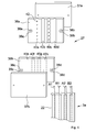
- the Fig. 1 shows an elevator system 100, as known from the prior art, for example in a illustrated 2: 1 suspension.
- an elevator car 2 In an elevator shaft 1, an elevator car 2 is movably arranged, which is connected via a support and propellant 3 with a movable counterweight 4.
- the support and propellant 3 is driven during operation by means of a traction sheave 5 of a drive unit 6, which are arranged in the uppermost region of the elevator shaft 1 in a machine room 12.
- the elevator car 2 and the counterweight 4 are guided by extending over the shaft height guide rails 7a and 7b and 7c.
- the elevator car 2 can serve a top floor door 8, further floor doors 9 and 10 and a lowest floor door 11 at a delivery height h.
- the elevator shaft 1 is formed by shaft side walls 15a and 15b, a shaft ceiling 13 and a shaft bottom 14 on which a shaft bottom buffer 19a for the counterweight 4 and two shaft bottom buffers 19b and 19c for the elevator car 2 are arranged.
- the support and propellant 3 is attached to a fixed attachment point or Tragstofffixige 16 a to the shaft ceiling 13 and guided parallel to the shaft side wall 15 a to a support roller 17 for the counterweight 4. From here again via the traction sheave 5, to a first deflection or support roller 18a and a second deflection or support roller 18b, the elevator car 2 nieschlingend, and to a second stationary attachment point or Tragstofffixtician 16b on the shaft ceiling 13th
- a contacting element 20a and 20b arranged at the respective ends of the support and propellant 3.
- a symbolically illustrated test circuit 23 with a test current IP can be applied, with the example, a simple continuity test of the supporting and propellant 3 can be realized.
- the Fig. 2 schematically shows a monitoring device 200a in an elevator installation 100a.
- a support and propellant 3a which essentially consists of four cords A1, B1, A2, B2 and a casing 22 essentially enveloping these cords A1, B1, A2, B2, is disposed at a first end 43a of the carrying and propelling means 3a, a contacting bridge 27 is connected, which connects the cord A1 to the cord A2 and thus forms a first circuit 21a.
- the contacting bridge 27 further connects the cord B1 to the cord B2, thus forming a second circuit 21b.
- a contacting element 20 Connected to a second end 43b of the supporting and propelling means 3a is a contacting element 20 which, corresponding to each cord A1, B1, A2, B2, has a contact 28a-28d.
- a switchable contacting device 29 has contact cams 30a and 30b which, in a first contact position KP1, make contact with the cords A1 and A2 of the first circuit 21a. In a second, shown in dashed line contact position KP2, the switchable contacting device 29 has contact with the cords B1 and B2 of the second circuit 21b.
- a test current IPa of a grounded ground 24 voltage source Ua to the Cord Al can be applied in a first switching position SP1.
- the test current IPa to the Cord B1 can be applied.
- test circuit 23a either the first circuit 21a or the second circuit 21b.
- the test circuit 23a further comprises a measuring device 25 whose measurement results can be forwarded to an evaluation unit 32 with an integrated computer 41.
- a connection point 34 may preferably be designed as a switch. From an optional contact point P, which is, for example, a deflection roller, measurement signals optionally pass directly via a line 33 into the evaluation unit 32. These measuring signals of the contact point P could alternatively also be supplied to the measuring device 25.
- FIG. 3 is in principle the monitoring device 200a or the elevator system 100a from the Fig. 2 shown again, however, in this Fig. 3 schematically shows how the support and propellant 3a a lift cage 2a in pulleys or support rollers 35a and 35b underschlingt and that there is a cross-circuit Qsch between the Cord Al and the Cord B1. Furthermore, it is shown that individual strands 26 of the cord Al have emerged from the sheath 22 and thus a cord break Cb is imminent or already present.
- the pulleys or support rollers 35a and 35b represent contact points P1 and P2, the hint to the test circuit 23a from the Fig. 2 are connected.
- a plurality of such carrying and blowing agents can be guided in a parallel arrangement.
- this monitoring device only one end of the connection to a measuring arrangement must be accessible, since the other end of the support and propellant must include only contact bridges.
- FIG. 4 schematically shows how a Kunststofftechniksmaschine 27 is configured by way of example.
- the support and propellant 3a is captured by two conductive contact plates 36a and 36b, and these two conductive contact plates 36a and 36b of two insulating plates 37a and 37b by means not shown screw.
- the screw no line bridge between the conductive Contact plates 36a and 36b can make holes 38a-38d, are used by the screws, each equipped with an insulator 39a-39d.
- the conductive contact plate 36a has concave grooves 40a-40d, of which only the concave grooves 40a and 40c have contact pins 42 piercing the sheath 22 of the supporting and propelling means 3a, so that the cords A1 and A2 are connected to each other.
- the conductive contact plate 36b has corresponding concave grooves 40e-40h of which only the concave grooves 40f and 40h are provided with contact pins 42, so that this contact plate 36b makes the electrical connection between the cords B1 and B2.
- the conductive contact plates 36a and 36b may alternatively be plates instead of one-piece plates, which merely have the necessary conductive connections or even only flexible cable connections.
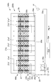
- FIG. 5 there is shown schematically a monitoring device 200b and thus an elevator system 100b in which a carrying and driving means 3b having twelve cords A1'-A6 'and B1'-B6' is used.
- the cords are divided into three groups of cords, which in turn are divided into two circuits.
- Amaschinetechniksmaschine 27a at a first end 43a 'of the supporting propellant 3b shows in contrast to a strictly alternating interconnection according to Fig.
- a contacting element 20a at a second end 43b 'of the carrying and driving means 3b comprises a preferably integrated switchable contacting device 29a in the form a time-demultiplexer that can time-controlled switch every single Cord A1'-A6 'and B1'-B6'.
- a test current IPb of a voltage source Ub grounded to a ground 24a is connected via a test circuit 23b and a switching device 31a, preferably also electronically and timed, to either the cord A1 'or the cord B1' and further to the cord A3 ', B3 'and the cords A5', B5 'can be applied.
- a current characteristic of the test current IPb at each individual Cord Al'-A6 'and B1'-B6' can be measured by a measuring device 25a and forwarded to an evaluation unit 32a with a preferably integrated computer 41a.
- the voltage source Ub is applied to the cord A3 'via the switching device 31a and the measuring device 25a detects a test current IPb at the cord A5', a cross-circuit between Cord A5 'and Cord A4' is established.
- Measuring signals from a contact point P 'can also pass directly to the evaluation unit 32a via a line 33a, but in principle can also be supplied to the measuring device 25a.
- the content of the examples can be combined.
- the 12 cords of the suspension according to Fig. 5 can be divided into two circuits to six cords or it can also be divided into two groups, each with two circuits to three cords. Also, as explained in section [0033], the ends of the cords in all the examples can be provided with specific resistances, whereby an even more accurate statement can be made about the state of the suspension element.
Landscapes
- Lift-Guide Devices, And Elevator Ropes And Cables (AREA)
- Maintenance And Inspection Apparatuses For Elevators (AREA)
- Testing Of Devices, Machine Parts, Or Other Structures Thereof (AREA)
Priority Applications (2)
| Application Number | Priority Date | Filing Date | Title |
|---|---|---|---|
| ES09180230T ES2409030T3 (es) | 2009-12-21 | 2009-12-21 | Revisión de un medio de soporte y de accionamiento de una instalación de ascensor |
| EP20090180230 EP2336072B1 (fr) | 2009-12-21 | 2009-12-21 | Contrôle d'un moyen de traction et d'entraînement d'une installation d'ascenseur |
Applications Claiming Priority (1)
| Application Number | Priority Date | Filing Date | Title |
|---|---|---|---|
| EP20090180230 EP2336072B1 (fr) | 2009-12-21 | 2009-12-21 | Contrôle d'un moyen de traction et d'entraînement d'une installation d'ascenseur |
Publications (2)
| Publication Number | Publication Date |
|---|---|
| EP2336072A1 true EP2336072A1 (fr) | 2011-06-22 |
| EP2336072B1 EP2336072B1 (fr) | 2013-02-27 |
Family
ID=42110041
Family Applications (1)
| Application Number | Title | Priority Date | Filing Date |
|---|---|---|---|
| EP20090180230 Not-in-force EP2336072B1 (fr) | 2009-12-21 | 2009-12-21 | Contrôle d'un moyen de traction et d'entraînement d'une installation d'ascenseur |
Country Status (2)
| Country | Link |
|---|---|
| EP (1) | EP2336072B1 (fr) |
| ES (1) | ES2409030T3 (fr) |
Cited By (4)
| Publication number | Priority date | Publication date | Assignee | Title |
|---|---|---|---|---|
| WO2013135285A1 (fr) * | 2012-03-14 | 2013-09-19 | Kone Corporation | Procédé de détection d'usure ou de défaillance dans un élément porteur de charge d'un ascenseur |
| WO2013153016A1 (fr) * | 2012-04-12 | 2013-10-17 | Inventio Ag | Installation d'ascenseur |
| WO2016083507A1 (fr) * | 2014-11-28 | 2016-06-02 | Inventio Ag | Installation d'ascenseur |
| US10426290B2 (en) | 2013-03-14 | 2019-10-01 | The Coca-Cola Company | Water distribution system for a beverage dispenser |
Families Citing this family (1)
| Publication number | Priority date | Publication date | Assignee | Title |
|---|---|---|---|---|
| US11718501B2 (en) | 2020-04-06 | 2023-08-08 | Otis Elevator Company | Elevator sheave wear detection |
Citations (8)
| Publication number | Priority date | Publication date | Assignee | Title |
|---|---|---|---|---|
| DE3934654A1 (de) | 1989-10-14 | 1991-05-23 | Sondermaschinenbau Peter Suhli | Auf bruch pruefbarer endlicher tragriemen und verfahren zum pruefen eines endlichen tragriemens auf bruch |
| EP1275608A1 (fr) | 2001-07-12 | 2003-01-15 | Inventio Ag | Dispositif pour la détection de l'usure des câbles porteurs |
| JP2003075495A (ja) * | 2001-08-30 | 2003-03-12 | Toshiba Elevator Co Ltd | エレベータの導通検査装置 |
| WO2005094248A2 (fr) | 2004-03-16 | 2005-10-13 | Otis Elevator Company | Procedes d'application de signaux electriques pour surveiller l'etat d'un element de support de charge d'un dispositif de levage |
| WO2005094250A2 (fr) | 2004-03-16 | 2005-10-13 | Otis Elevator Company | Systeme et procede de surveillance de la resistance a la traction d'un support |
| WO2005094249A2 (fr) | 2004-03-16 | 2005-10-13 | Otis Elevator Company | Dispositif de connexion electrique utilise avec des elements de support de charge d'un dispositif de levage |
| US7123030B2 (en) | 1999-03-29 | 2006-10-17 | Otis Elevator Company | Method and apparatus for detecting elevator rope degradation using electrical resistance |
| WO2006127059A2 (fr) | 2005-05-20 | 2006-11-30 | Otis Elevator Company | Connecteur electrique pour percer un element conducteur |
-
2009
- 2009-12-21 ES ES09180230T patent/ES2409030T3/es active Active
- 2009-12-21 EP EP20090180230 patent/EP2336072B1/fr not_active Not-in-force
Patent Citations (8)
| Publication number | Priority date | Publication date | Assignee | Title |
|---|---|---|---|---|
| DE3934654A1 (de) | 1989-10-14 | 1991-05-23 | Sondermaschinenbau Peter Suhli | Auf bruch pruefbarer endlicher tragriemen und verfahren zum pruefen eines endlichen tragriemens auf bruch |
| US7123030B2 (en) | 1999-03-29 | 2006-10-17 | Otis Elevator Company | Method and apparatus for detecting elevator rope degradation using electrical resistance |
| EP1275608A1 (fr) | 2001-07-12 | 2003-01-15 | Inventio Ag | Dispositif pour la détection de l'usure des câbles porteurs |
| JP2003075495A (ja) * | 2001-08-30 | 2003-03-12 | Toshiba Elevator Co Ltd | エレベータの導通検査装置 |
| WO2005094248A2 (fr) | 2004-03-16 | 2005-10-13 | Otis Elevator Company | Procedes d'application de signaux electriques pour surveiller l'etat d'un element de support de charge d'un dispositif de levage |
| WO2005094250A2 (fr) | 2004-03-16 | 2005-10-13 | Otis Elevator Company | Systeme et procede de surveillance de la resistance a la traction d'un support |
| WO2005094249A2 (fr) | 2004-03-16 | 2005-10-13 | Otis Elevator Company | Dispositif de connexion electrique utilise avec des elements de support de charge d'un dispositif de levage |
| WO2006127059A2 (fr) | 2005-05-20 | 2006-11-30 | Otis Elevator Company | Connecteur electrique pour percer un element conducteur |
Cited By (8)
| Publication number | Priority date | Publication date | Assignee | Title |
|---|---|---|---|---|
| WO2013135285A1 (fr) * | 2012-03-14 | 2013-09-19 | Kone Corporation | Procédé de détection d'usure ou de défaillance dans un élément porteur de charge d'un ascenseur |
| WO2013153016A1 (fr) * | 2012-04-12 | 2013-10-17 | Inventio Ag | Installation d'ascenseur |
| US10426290B2 (en) | 2013-03-14 | 2019-10-01 | The Coca-Cola Company | Water distribution system for a beverage dispenser |
| WO2016083507A1 (fr) * | 2014-11-28 | 2016-06-02 | Inventio Ag | Installation d'ascenseur |
| CN107428506A (zh) * | 2014-11-28 | 2017-12-01 | 因温特奥股份公司 | 电梯设备 |
| AU2015352498B2 (en) * | 2014-11-28 | 2018-12-13 | Inventio Ag | Elevator system |
| CN107428506B (zh) * | 2014-11-28 | 2019-06-21 | 因温特奥股份公司 | 电梯设备 |
| US10611604B2 (en) | 2014-11-28 | 2020-04-07 | Inventio Ag | Elevator system |
Also Published As
| Publication number | Publication date |
|---|---|
| ES2409030T3 (es) | 2013-06-24 |
| EP2336072B1 (fr) | 2013-02-27 |
Similar Documents
| Publication | Publication Date | Title |
|---|---|---|
| EP2516313B1 (fr) | Surveillance d'un moyen de support et d'entraînement d'un système d'ascenseur | |
| EP2367747B1 (fr) | Procédé destiné à la surveillance d'un moyen de portage d'ascenseur, dispositif de surveillance d'un moyen de portage d'ascenseur et installation d'ascenseur dotée d'un tel dispositif de surveillance | |
| EP2935071B1 (fr) | Installation d'ascenseur avec dispositif de surveillance et methode de surveillance d'une installation d'ascenseur | |
| EP2336072B1 (fr) | Contrôle d'un moyen de traction et d'entraînement d'une installation d'ascenseur | |
| DE102006024692B4 (de) | Verfahren und Vorrichtung zur Detektion des Belegt- oder Freizustandes eines Gleisabschnittes | |
| EP2760774B1 (fr) | Dispositif et procédé destinés à la surveillance de portes palières | |
| DE19800714A1 (de) | Verfahren zur Wartung einer Aufzugsanlage und Aufzugsanlage | |
| WO2013153016A1 (fr) | Installation d'ascenseur | |
| EP3385007B1 (fr) | Dispositif à pièce d'usure et dispositif de mesure d'usure | |
| DE102013013471A1 (de) | Verfahren zur Bestimmung der Zuleitungsimpedanz in mehrzelligen Batteriepacks zur Leitungsfehlererkennung | |
| DE102016104725A1 (de) | Faserverstärkter Verbundwerkstoff mit einer Sensoranordnung zur Strukturüberwachung des Verbundwerkstoffs | |
| EP1530040B1 (fr) | Méthode et appareil pour contrôler des moyens de suspension | |
| EP3224181B1 (fr) | Ascenseur | |
| EP3209989A1 (fr) | Installation d'élévation | |
| EP3218675B1 (fr) | Procédé et dispositif de détection, d'évaluation et d'affichage de valeurs de mesure de moteurs d'entraînements électriques | |
| WO1997020224A2 (fr) | Procede et dispositif pour le controle de dispositifs electriques d'entrainement | |
| DE10324919A1 (de) | Flachleiter | |
| EP3741606B1 (fr) | Dispositif et procédé de détection de l'usure d'un système de transport pourvu de contacts glissants | |
| EP1190403B1 (fr) | Circuit pour enclencher et actionner des appareils connectes en serie dans une installation de commande et de transmission de donnees, en ce qui concerne leur tension d'alimentation | |
| EP3042874B1 (fr) | Surveillance de courroie d'ascenseur | |
| EP3617114A1 (fr) | Procédé et dispositif de surveillance permettant de surveiller un dérailleur de sécurité dans une installation d'ascenseur | |
| EP2808285B1 (fr) | Installation d'ascenseur | |
| DE10219635B3 (de) | Vorrichtung zur Fehlererkennung in Verkabelungen | |
| DE202021102533U1 (de) | Motorfeedbacksystem | |
| EP3262393A1 (fr) | Système de mesure de vibrations |
Legal Events
| Date | Code | Title | Description |
|---|---|---|---|
| PUAI | Public reference made under article 153(3) epc to a published international application that has entered the european phase |
Free format text: ORIGINAL CODE: 0009012 |
|
| AK | Designated contracting states |
Kind code of ref document: A1 Designated state(s): AT BE BG CH CY CZ DE DK EE ES FI FR GB GR HR HU IE IS IT LI LT LU LV MC MK MT NL NO PL PT RO SE SI SK SM TR |
|
| AX | Request for extension of the european patent |
Extension state: AL BA RS |
|
| 17P | Request for examination filed |
Effective date: 20111202 |
|
| 17Q | First examination report despatched |
Effective date: 20120113 |
|
| GRAP | Despatch of communication of intention to grant a patent |
Free format text: ORIGINAL CODE: EPIDOSNIGR1 |
|
| GRAS | Grant fee paid |
Free format text: ORIGINAL CODE: EPIDOSNIGR3 |
|
| GRAA | (expected) grant |
Free format text: ORIGINAL CODE: 0009210 |
|
| AK | Designated contracting states |
Kind code of ref document: B1 Designated state(s): AT BE BG CH CY CZ DE DK EE ES FI FR GB GR HR HU IE IS IT LI LT LU LV MC MK MT NL NO PL PT RO SE SI SK SM TR |
|
| REG | Reference to a national code |
Ref country code: GB Ref legal event code: FG4D Free format text: NOT ENGLISH |
|
| REG | Reference to a national code |
Ref country code: CH Ref legal event code: EP |
|
| REG | Reference to a national code |
Ref country code: AT Ref legal event code: REF Ref document number: 598385 Country of ref document: AT Kind code of ref document: T Effective date: 20130315 |
|
| REG | Reference to a national code |
Ref country code: IE Ref legal event code: FG4D Free format text: LANGUAGE OF EP DOCUMENT: GERMAN |
|
| REG | Reference to a national code |
Ref country code: DE Ref legal event code: R096 Ref document number: 502009006359 Country of ref document: DE Effective date: 20130425 |
|
| REG | Reference to a national code |
Ref country code: ES Ref legal event code: FG2A Ref document number: 2409030 Country of ref document: ES Kind code of ref document: T3 Effective date: 20130624 |
|
| REG | Reference to a national code |
Ref country code: LT Ref legal event code: MG4D |
|
| PG25 | Lapsed in a contracting state [announced via postgrant information from national office to epo] |
Ref country code: LT Free format text: LAPSE BECAUSE OF FAILURE TO SUBMIT A TRANSLATION OF THE DESCRIPTION OR TO PAY THE FEE WITHIN THE PRESCRIBED TIME-LIMIT Effective date: 20130227 Ref country code: IS Free format text: LAPSE BECAUSE OF FAILURE TO SUBMIT A TRANSLATION OF THE DESCRIPTION OR TO PAY THE FEE WITHIN THE PRESCRIBED TIME-LIMIT Effective date: 20130627 Ref country code: BG Free format text: LAPSE BECAUSE OF FAILURE TO SUBMIT A TRANSLATION OF THE DESCRIPTION OR TO PAY THE FEE WITHIN THE PRESCRIBED TIME-LIMIT Effective date: 20130527 Ref country code: SE Free format text: LAPSE BECAUSE OF FAILURE TO SUBMIT A TRANSLATION OF THE DESCRIPTION OR TO PAY THE FEE WITHIN THE PRESCRIBED TIME-LIMIT Effective date: 20130227 Ref country code: NO Free format text: LAPSE BECAUSE OF FAILURE TO SUBMIT A TRANSLATION OF THE DESCRIPTION OR TO PAY THE FEE WITHIN THE PRESCRIBED TIME-LIMIT Effective date: 20130527 |
|
| REG | Reference to a national code |
Ref country code: NL Ref legal event code: VDEP Effective date: 20130227 |
|
| PG25 | Lapsed in a contracting state [announced via postgrant information from national office to epo] |
Ref country code: GR Free format text: LAPSE BECAUSE OF FAILURE TO SUBMIT A TRANSLATION OF THE DESCRIPTION OR TO PAY THE FEE WITHIN THE PRESCRIBED TIME-LIMIT Effective date: 20130528 Ref country code: SI Free format text: LAPSE BECAUSE OF FAILURE TO SUBMIT A TRANSLATION OF THE DESCRIPTION OR TO PAY THE FEE WITHIN THE PRESCRIBED TIME-LIMIT Effective date: 20130227 Ref country code: PL Free format text: LAPSE BECAUSE OF FAILURE TO SUBMIT A TRANSLATION OF THE DESCRIPTION OR TO PAY THE FEE WITHIN THE PRESCRIBED TIME-LIMIT Effective date: 20130227 Ref country code: PT Free format text: LAPSE BECAUSE OF FAILURE TO SUBMIT A TRANSLATION OF THE DESCRIPTION OR TO PAY THE FEE WITHIN THE PRESCRIBED TIME-LIMIT Effective date: 20130627 Ref country code: FI Free format text: LAPSE BECAUSE OF FAILURE TO SUBMIT A TRANSLATION OF THE DESCRIPTION OR TO PAY THE FEE WITHIN THE PRESCRIBED TIME-LIMIT Effective date: 20130227 Ref country code: LV Free format text: LAPSE BECAUSE OF FAILURE TO SUBMIT A TRANSLATION OF THE DESCRIPTION OR TO PAY THE FEE WITHIN THE PRESCRIBED TIME-LIMIT Effective date: 20130227 |
|
| PG25 | Lapsed in a contracting state [announced via postgrant information from national office to epo] |
Ref country code: HR Free format text: LAPSE BECAUSE OF FAILURE TO SUBMIT A TRANSLATION OF THE DESCRIPTION OR TO PAY THE FEE WITHIN THE PRESCRIBED TIME-LIMIT Effective date: 20130227 |
|
| PG25 | Lapsed in a contracting state [announced via postgrant information from national office to epo] |
Ref country code: CZ Free format text: LAPSE BECAUSE OF FAILURE TO SUBMIT A TRANSLATION OF THE DESCRIPTION OR TO PAY THE FEE WITHIN THE PRESCRIBED TIME-LIMIT Effective date: 20130227 Ref country code: RO Free format text: LAPSE BECAUSE OF FAILURE TO SUBMIT A TRANSLATION OF THE DESCRIPTION OR TO PAY THE FEE WITHIN THE PRESCRIBED TIME-LIMIT Effective date: 20130227 Ref country code: EE Free format text: LAPSE BECAUSE OF FAILURE TO SUBMIT A TRANSLATION OF THE DESCRIPTION OR TO PAY THE FEE WITHIN THE PRESCRIBED TIME-LIMIT Effective date: 20130227 Ref country code: NL Free format text: LAPSE BECAUSE OF FAILURE TO SUBMIT A TRANSLATION OF THE DESCRIPTION OR TO PAY THE FEE WITHIN THE PRESCRIBED TIME-LIMIT Effective date: 20130227 Ref country code: DK Free format text: LAPSE BECAUSE OF FAILURE TO SUBMIT A TRANSLATION OF THE DESCRIPTION OR TO PAY THE FEE WITHIN THE PRESCRIBED TIME-LIMIT Effective date: 20130227 Ref country code: SK Free format text: LAPSE BECAUSE OF FAILURE TO SUBMIT A TRANSLATION OF THE DESCRIPTION OR TO PAY THE FEE WITHIN THE PRESCRIBED TIME-LIMIT Effective date: 20130227 |
|
| PG25 | Lapsed in a contracting state [announced via postgrant information from national office to epo] |
Ref country code: CY Free format text: LAPSE BECAUSE OF FAILURE TO SUBMIT A TRANSLATION OF THE DESCRIPTION OR TO PAY THE FEE WITHIN THE PRESCRIBED TIME-LIMIT Effective date: 20130227 |
|
| PLBE | No opposition filed within time limit |
Free format text: ORIGINAL CODE: 0009261 |
|
| STAA | Information on the status of an ep patent application or granted ep patent |
Free format text: STATUS: NO OPPOSITION FILED WITHIN TIME LIMIT |
|
| 26N | No opposition filed |
Effective date: 20131128 |
|
| REG | Reference to a national code |
Ref country code: DE Ref legal event code: R097 Ref document number: 502009006359 Country of ref document: DE Effective date: 20131128 |
|
| BERE | Be: lapsed |
Owner name: INVENTIO A.G. Effective date: 20131231 |
|
| PG25 | Lapsed in a contracting state [announced via postgrant information from national office to epo] |
Ref country code: MC Free format text: LAPSE BECAUSE OF FAILURE TO SUBMIT A TRANSLATION OF THE DESCRIPTION OR TO PAY THE FEE WITHIN THE PRESCRIBED TIME-LIMIT Effective date: 20130227 Ref country code: LU Free format text: LAPSE BECAUSE OF FAILURE TO SUBMIT A TRANSLATION OF THE DESCRIPTION OR TO PAY THE FEE WITHIN THE PRESCRIBED TIME-LIMIT Effective date: 20131221 |
|
| REG | Reference to a national code |
Ref country code: IE Ref legal event code: MM4A |
|
| PG25 | Lapsed in a contracting state [announced via postgrant information from national office to epo] |
Ref country code: BE Free format text: LAPSE BECAUSE OF NON-PAYMENT OF DUE FEES Effective date: 20131231 Ref country code: IE Free format text: LAPSE BECAUSE OF NON-PAYMENT OF DUE FEES Effective date: 20131221 |
|
| PG25 | Lapsed in a contracting state [announced via postgrant information from national office to epo] |
Ref country code: SM Free format text: LAPSE BECAUSE OF FAILURE TO SUBMIT A TRANSLATION OF THE DESCRIPTION OR TO PAY THE FEE WITHIN THE PRESCRIBED TIME-LIMIT Effective date: 20130227 |
|
| PG25 | Lapsed in a contracting state [announced via postgrant information from national office to epo] |
Ref country code: TR Free format text: LAPSE BECAUSE OF FAILURE TO SUBMIT A TRANSLATION OF THE DESCRIPTION OR TO PAY THE FEE WITHIN THE PRESCRIBED TIME-LIMIT Effective date: 20130227 |
|
| PG25 | Lapsed in a contracting state [announced via postgrant information from national office to epo] |
Ref country code: MK Free format text: LAPSE BECAUSE OF FAILURE TO SUBMIT A TRANSLATION OF THE DESCRIPTION OR TO PAY THE FEE WITHIN THE PRESCRIBED TIME-LIMIT Effective date: 20130227 Ref country code: HU Free format text: LAPSE BECAUSE OF FAILURE TO SUBMIT A TRANSLATION OF THE DESCRIPTION OR TO PAY THE FEE WITHIN THE PRESCRIBED TIME-LIMIT; INVALID AB INITIO Effective date: 20091221 |
|
| PG25 | Lapsed in a contracting state [announced via postgrant information from national office to epo] |
Ref country code: MT Free format text: LAPSE BECAUSE OF FAILURE TO SUBMIT A TRANSLATION OF THE DESCRIPTION OR TO PAY THE FEE WITHIN THE PRESCRIBED TIME-LIMIT Effective date: 20130227 |
|
| REG | Reference to a national code |
Ref country code: FR Ref legal event code: PLFP Year of fee payment: 7 |
|
| REG | Reference to a national code |
Ref country code: AT Ref legal event code: MM01 Ref document number: 598385 Country of ref document: AT Kind code of ref document: T Effective date: 20141221 |
|
| PG25 | Lapsed in a contracting state [announced via postgrant information from national office to epo] |
Ref country code: AT Free format text: LAPSE BECAUSE OF NON-PAYMENT OF DUE FEES Effective date: 20141221 |
|
| REG | Reference to a national code |
Ref country code: FR Ref legal event code: PLFP Year of fee payment: 8 |
|
| REG | Reference to a national code |
Ref country code: FR Ref legal event code: PLFP Year of fee payment: 9 |
|
| PGFP | Annual fee paid to national office [announced via postgrant information from national office to epo] |
Ref country code: FR Payment date: 20171221 Year of fee payment: 9 |
|
| PGFP | Annual fee paid to national office [announced via postgrant information from national office to epo] |
Ref country code: CH Payment date: 20171220 Year of fee payment: 9 Ref country code: GB Payment date: 20171221 Year of fee payment: 9 |
|
| PGFP | Annual fee paid to national office [announced via postgrant information from national office to epo] |
Ref country code: ES Payment date: 20180124 Year of fee payment: 9 |
|
| PGFP | Annual fee paid to national office [announced via postgrant information from national office to epo] |
Ref country code: IT Payment date: 20171221 Year of fee payment: 9 |
|
| REG | Reference to a national code |
Ref country code: CH Ref legal event code: PL |
|
| GBPC | Gb: european patent ceased through non-payment of renewal fee |
Effective date: 20181221 |
|
| PG25 | Lapsed in a contracting state [announced via postgrant information from national office to epo] |
Ref country code: IT Free format text: LAPSE BECAUSE OF NON-PAYMENT OF DUE FEES Effective date: 20181221 Ref country code: FR Free format text: LAPSE BECAUSE OF NON-PAYMENT OF DUE FEES Effective date: 20181231 |
|
| PG25 | Lapsed in a contracting state [announced via postgrant information from national office to epo] |
Ref country code: CH Free format text: LAPSE BECAUSE OF NON-PAYMENT OF DUE FEES Effective date: 20181231 Ref country code: GB Free format text: LAPSE BECAUSE OF NON-PAYMENT OF DUE FEES Effective date: 20181221 Ref country code: LI Free format text: LAPSE BECAUSE OF NON-PAYMENT OF DUE FEES Effective date: 20181231 |
|
| REG | Reference to a national code |
Ref country code: ES Ref legal event code: FD2A Effective date: 20200205 |
|
| PG25 | Lapsed in a contracting state [announced via postgrant information from national office to epo] |
Ref country code: ES Free format text: LAPSE BECAUSE OF NON-PAYMENT OF DUE FEES Effective date: 20181222 |
|
| PGFP | Annual fee paid to national office [announced via postgrant information from national office to epo] |
Ref country code: DE Payment date: 20211228 Year of fee payment: 13 |
|
| REG | Reference to a national code |
Ref country code: DE Ref legal event code: R119 Ref document number: 502009006359 Country of ref document: DE |
|
| PG25 | Lapsed in a contracting state [announced via postgrant information from national office to epo] |
Ref country code: DE Free format text: LAPSE BECAUSE OF NON-PAYMENT OF DUE FEES Effective date: 20230701 |