EP2336072A1 - Monitoring of a load bearing and drive device of a lift assembly - Google Patents
Monitoring of a load bearing and drive device of a lift assembly Download PDFInfo
- Publication number
- EP2336072A1 EP2336072A1 EP09180230A EP09180230A EP2336072A1 EP 2336072 A1 EP2336072 A1 EP 2336072A1 EP 09180230 A EP09180230 A EP 09180230A EP 09180230 A EP09180230 A EP 09180230A EP 2336072 A1 EP2336072 A1 EP 2336072A1
- Authority
- EP
- European Patent Office
- Prior art keywords
- circuit
- cord
- cords
- contacting
- carrying
- Prior art date
- Legal status (The legal status is an assumption and is not a legal conclusion. Google has not performed a legal analysis and makes no representation as to the accuracy of the status listed.)
- Granted
Links
Images


Classifications
-
- B—PERFORMING OPERATIONS; TRANSPORTING
- B66—HOISTING; LIFTING; HAULING
- B66B—ELEVATORS; ESCALATORS OR MOVING WALKWAYS
- B66B7/00—Other common features of elevators
- B66B7/12—Checking, lubricating, or cleaning means for ropes, cables or guides
- B66B7/1207—Checking means
- B66B7/1215—Checking means specially adapted for ropes or cables
- B66B7/1223—Checking means specially adapted for ropes or cables by analysing electric variables
Definitions
- the present invention relates to an elevator installation, in which at least one elevator car or at least one counterweight is moved in opposite directions in an elevator shaft, wherein the at least one elevator car and the at least one counterweight run along guide rails, carried by one or more carrying and propelling means and driven by a traction sheave of a drive unit.
- the present invention relates in particular to the carrying and blowing agent, namely a method for checking or monitoring the carrying and blowing agent of the elevator installation and a device according to the invention for carrying out this method.
- supporting and blowing agents consist of at least one current-conducting steel cable and non-conductive sheaths or made of specialty plastics ropes, in which a conductor is incorporated.
- a test current can be applied for monitoring the individual supporting cable or the individual supporting cables - also called cords.
- the current flow or the current intensity, the voltage, the electrical resistance or the electrical conductivity is measured and thus provides information about the integrity or the degree of wear of the carrier and propellant.
- the published patent application DE-A1-39 34 654 a serial connection of all individual cords and an ammeter, or, instead of an ammeter, an electronic circuit in which the base resistance of an emitter-connected transistor is measured.
- the patent US B2-7,123,030 discloses a calculation of the electrical resistance by a measurement of the current voltage by means of a so-called Kelvin bridge and a comparison of the thus determined voltage value with an input reference value.
- the international publication WO-A2-2005 / 094250 discloses a temperature-dependent measurement of the electrical resistance or the electrical conductivity, in which the different environmental and thus also assumed carrier temperature is taken into account, which can be very different, especially in high elevator shafts.
- EP-A1-1 275 608 An application of the same applicant as the present application discloses a monitoring of the sheath by applying a positive pole of a voltage source to the cords, so that in case of a defective sheath a ground contact is made.
- An object of the present invention is to propose a monitoring and monitoring device for carrying and propellant, the cost-optimized provides more accurate or qualitatively classifiable information about the state of the carrier and propellant and thus achieves a higher level of security for the elevator system is to be avoided or costly too early replacement of the carrier and propellant.
- connection or interconnection of the in a row and parallel to each other in a common sheath arranged cords is basically such that each individual cord of the first circuit of at least one cord of the second circuit is adjacent and each individual cord of the second circuit of at least one cord of the first circuit is adjacent.
- a cord of the first circuit and in each case a cord of the second circuit are arranged in an alternating sequence.
- the cords form a row in which the first cord belongs to the first circuit and is followed by a second cord that is part of the second circuit.
- This second cord is followed by a third cord, which in turn is part of the first circuit.
- This third cord is followed by a fourth cord, which is part of the second circuit, etc.
- a second embodiment of an interconnection arranges the cords so that in each case one cord of a circuit is adjacent to a cord of the other circuit, but this is done in pairs.
- the sequence is thus, for example, assuming a carrying and blowing agent with eight cords and when the cords of the first circuit with A and those of the second circuit with B, A1-B1-B2-A2-A3-B3-B4 -A4.
- the first embodiment variant of the interconnection it would be A1-B1-A2-B2-A3-B3-A4-B4.
- a basic variant of an arrangement thus provides a carrying and propellant having at least four conductive cords.
- This carrying and blowing agent is substantially encased, but has at the one end the common Contacting element or at the other end of the Kunststoff michs Kunststoff, which are in each case in contact with the conductive cords in the above-mentioned interconnections. This can be ensured by the conductive cords are freed from the sheath at these points, or have the contacting element or the Kunststoff Industriess Hampshire - preferably concave grooves ausformende - contact surfaces which penetrate the sheathing withmaschine Sammlungsnadeln.
- Contacting elements as they can basically be found at one end of the carrying and propellant according to a corresponding monitoring device use, for example, in the international application PCT / EP2009 / 064812 or in the European publication EP-A1-127 56 08 disclosed.
- the contacting elements disclosed in these documents can be arranged not only at the ends of the carrier and propellant, but optionally also between them.
- Other contacting elements are for example in the publications WO-A2-2005 / 094249 .
- a contacting element corresponding to the monitoring device is preferably connected to a contacting device and this in turn preferably connected to an evaluation unit, which evaluates the signal or the relevant current characteristic or several relevant current characteristics at the cords of the first circuit in a first test step and in one next, later test step evaluates the signal or the relevant current characteristic or several significant current characteristics at the cords of the second circuit.
- the measurement of the cords of the second circuit can take place, the contacting device or with their associated evaluation switchable or configured as a shift register.
- a first embodiment variant of this switchable contacting device works mechanically and manually.
- it has a contact strip with elevations and depressions, which correspond not every adjacent cord, but only every other cord within its parallel arrangement in the carrying and blowing agent.
- the elevations preferably have contact cams, which thus make contact in a first contact position of the switchable contacting device only to corresponding contact surfaces on the cords of the first circuit.
- a second embodiment of the switchable contacting device still has the described contact strip within the guide carriage, but instead of the manually operated lever, an electromechanical actuator, which is preferably actuated automatically by means of a timer.
- a third embodiment variant of the switchable contacting device works purely electronically.
- the contacts to both the cords of the first circuit, as well as the cords of the second circuit physically exist, with appropriate electronic components - preferably again by means of an automatic timing - so openable and closable that the measuring according to the first test step and then the measuring according to the second test step can be done.
- electronic switching devices or electronic shift registers or so-called demultiplexer or time-demultiplexer known to a person skilled in the art and thus not Subject of a description within this patent application.
- the contacting bridge preferably comprises two contact plates, which preferably enclose the corresponding cords, which have been removed correspondingly from the casing, with concave grooves. Between the contact plates, a third, insulating intermediate plate is arranged and all three plates are taken, for example, with screw; Clamping the leading cords here.
- the screw connections are preferably guided through insulated bores and underlaid with insulating discs, so that no electrical contact between the first and the second contact plate is possible.
- a further embodiment variant of amaschine ists Kunststoff provides that the conductive cords are not freed from their sheath and the preferably concave grooves in the contact plates have contact pins which pierce the sheath of the corresponding cords.
- the sheathing of the carrying and propellant acts as an insulator, so that it is possible to dispense with the third, insulating intermediate plate.
- the contact plates of both embodiments are preferably wider than the support and propellant, so that attachment to the end of the support and propellant beyond, but also this side of the attachment point of the support and propellant in the shaft, on the counterweight or on the elevator car is possible.
- a monitoring device further comprises at least one voltage source, which is connectable to the support and propellant and a the state of the support and Propellant corresponding test current causes.
- a first voltage source corresponding to a first test current to a cord of the first circuit and a second voltage source with a second, preferably different from the first voltage source characteristic to a cord of the second circuit can be applied.
- the two voltage sources are not mandatory, but preferably automatically switched on and off manually if necessary or by means of a timer.
- the voltage source can be switched by means of a switching device into a first and a second switching position.
- the test current can be applied to a cord or to the contact plate of the first circuit, and in the second switching position to a cord or to the contact plate of the second circuit.
- This switching device for the voltage source can also - like the switchable contacting device - be designed to be manually operated.
- An electromechanical embodiment variant thereof is preferably timed automatically and coupled with the then also electromechanically switchable contacting device so that every other switching of the latter, the switching device of the voltage source mitschaltet.
- the switching device of the voltage source can also be implemented purely electronically and is preferably coupled to a likewise purely electronic configuration variant of the switchable contacting device.
- a cord usually the first edge cord
- the voltage source is applied to a cord, usually the first edge cord, of the first circuit.
- a cord usually the first edge cord
- the test current can not be measured on any of the cords of the first circuit, then the one to which the test current has been applied is broken - for example, the first edge cord.
- the contact position of the contacting element or the evaluation unit connected thereto is changed from the first contact position to the cords of the first circuit to the second contact position to the cords of the second circuit by means of a switching of the switchable contacting device.
- no voltage is applied to these cords of the second circuit, but if a current characteristic can still be measured, there is a short circuit between the cords concerned and one or more adjacent cords.
- a second test step the application of the voltage source to a cord of the first circuit is switched to applying the voltage source to a cord of the second circuit. This may be done, for example, on the second cord or, with an even total number of cords, on the second edge cord opposite the first edge cord on the other side of the support and propellant.
- the test current it is checked on all cords of the second circuit whether the test current can be measured. If this is not the case on a cord of the second circuit, then this cord is broken. If the test current can not be measured at any cord of the second circuit, then that cord is broken, to which the test current has been applied, for example, the second cord or the second edge cord.
- the now present contact position is switched back to the cords of the second circuit to the contact position to the cords of the first circuit and determined analogously to the first test step, if there is a short circuit.
- a further embodiment provides that the aforementioned first test step and the following second test step are repeated in the further sequence for all remaining cords. This further enhances informative value about the condition of the suspension element.
- specific characteristic resistors which may for example be integrated into the connections of the cords in the contacting bridge - as disclosed in the parallel application for monitoring a carrier and propellant -, a further improvement in the diagnosis of the condition of the suspension element can be achieved .
- a certain characteristic resistor is arranged at each end of a cord of the support and drive belt. Using this teaching can now be determined more precisely with the present monitoring device based on a detected resistance, or the corresponding test current, where, for example, a cross-circuit between cords is present.
- This evaluation unit preferably has a computer, which on the one hand is able to compare the measurement result of the first test step with the measurement result of the second test step and thus determine which cords have cross-connection to each other.
- the computer is able to issue a release message or a - preferably staggered - warning message or - preferably via a coupling to a computer of the elevator control - to stop the operation of the elevator installation.
- a precise localization of the diagnosed damage can be made.
- Another contact point of the respective test circuit - be it the first or the second circuit of the respective cords comprising - can be arranged at one or more points at which or on which the carrying and blowing agent passes during operation.
- This point can, for example, be an arbitrary deflection roller, be it a stationary one in the elevator shaft arranged deflection roller or else the or one of the deflection rollers of the counterweight or the elevator car.
- retainer ie a derailment protection, which the deflection rollers usually have.
- the point is conductive and can be grounded - in the case of operating the monitoring device with DC - or a voltage can be applied to the point - in the case of operating the monitoring device with AC - and in principle a contact with the conductive part or the conductive parts of a carrier and propellant is possible.
- This latter contact between the point, for example, the guide roller, and the conductive part or the conductive parts of the support and propellant can be realized, for example, the conductive cords of the support and propellant not completely, but only substantially with non-conductive plastic is sheathed. There remain juxtaposed conductive points or even entire free parts of the cross-sectional circumference, which extend over the entire unwinding length of the support and propellant and can be in electrical contact with the deflection roller.
- Another way to make the contact between the cords and the pulley or the point with the third resistor is the incorporation of conductive strands in the sheath of the support and propellant.
- a carrying and blowing agent with a conductive sheath is possible, but then preferably has an insulating layer between the conductive cord and the conductive sheath.
- the cords are thus connected to voltage sources in such a way that specific total resistances, current intensities or-given a constant voltage source-specific voltages at the measuring points result, depending on the respective failure mode.
- the respective measured values can be clearly assigned to a respective damage event.
- the measurement can be queried both permanently and at intervals or only as needed before and / or during each trip as a corresponding condition for a ride release.
- the detection or the calculation of the measured values described is computer-assisted and automatic and can be displayed on a display or monitor.
- the computer of the evaluation unit is preferably further able to save the occurrence of damage and thus to create a damage cluster image.
- a carrier and propellant with For example, 12 cords, in which only rarely and with low intensity occurs a cross-circuit, can still be safely used for a certain time. This certain waiting period is recorded by the computer and shortened again or leads to a shutdown of the elevator system, if the extent of the damage should expand accordingly or another damage event should be added.
- 12 cords can be made by a previously described division into three groups of four cords, which are then divided into two circuits, a more accurate statement on the condition of the carrying and propellant.
- the disclosed embodiments of a monitoring device can preferably be combined with a flexible counter, so that further information flows into the monitoring device, which is preferably computer-assisted, and thus the determination of the ability to discard a carrier and propellant becomes even more reliable.
- the measurement may relate to the following current characteristics: resistance and / or a resistance characteristic, current, voltage, frequency, inductance, capacitance or combinations thereof.
- monitoring of a carrying and propellant usually contains several partial monitoring. For example, continuous monitoring, as described above, takes place. At certain intervals, visual checks are usually carried out to determine external damage and, depending on a period of operation (number of trips, etc.), detailed checks are carried out, for example by means of transmission or magnetic-inductive test methods. In many cases there are also time criteria for the determination the state of the support belt and drive belt taken into account, for example, if an aging-related embrittlement of a jacket is to be expected.
- a selection or determination of the required checks is usually made depending on the type of elevator installation, taking into account load, operating cycles, frequency of use, external conditions, etc.
- the aforementioned computer is preferably on the one hand in a position to cumulatively take into account all evaluation criteria and on the other hand to issue a corresponding release message, a service indicator, a stop signal, but also information about the actual state of the carrier and propellant, as well send a message to the owner or service company.
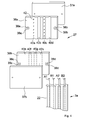
- the Fig. 1 shows an elevator system 100, as known from the prior art, for example in a illustrated 2: 1 suspension.
- an elevator car 2 In an elevator shaft 1, an elevator car 2 is movably arranged, which is connected via a support and propellant 3 with a movable counterweight 4.
- the support and propellant 3 is driven during operation by means of a traction sheave 5 of a drive unit 6, which are arranged in the uppermost region of the elevator shaft 1 in a machine room 12.
- the elevator car 2 and the counterweight 4 are guided by extending over the shaft height guide rails 7a and 7b and 7c.
- the elevator car 2 can serve a top floor door 8, further floor doors 9 and 10 and a lowest floor door 11 at a delivery height h.
- the elevator shaft 1 is formed by shaft side walls 15a and 15b, a shaft ceiling 13 and a shaft bottom 14 on which a shaft bottom buffer 19a for the counterweight 4 and two shaft bottom buffers 19b and 19c for the elevator car 2 are arranged.
- the support and propellant 3 is attached to a fixed attachment point or Tragstofffixige 16 a to the shaft ceiling 13 and guided parallel to the shaft side wall 15 a to a support roller 17 for the counterweight 4. From here again via the traction sheave 5, to a first deflection or support roller 18a and a second deflection or support roller 18b, the elevator car 2 nieschlingend, and to a second stationary attachment point or Tragstofffixtician 16b on the shaft ceiling 13th
- a contacting element 20a and 20b arranged at the respective ends of the support and propellant 3.
- a symbolically illustrated test circuit 23 with a test current IP can be applied, with the example, a simple continuity test of the supporting and propellant 3 can be realized.
- the Fig. 2 schematically shows a monitoring device 200a in an elevator installation 100a.
- a support and propellant 3a which essentially consists of four cords A1, B1, A2, B2 and a casing 22 essentially enveloping these cords A1, B1, A2, B2, is disposed at a first end 43a of the carrying and propelling means 3a, a contacting bridge 27 is connected, which connects the cord A1 to the cord A2 and thus forms a first circuit 21a.
- the contacting bridge 27 further connects the cord B1 to the cord B2, thus forming a second circuit 21b.
- a contacting element 20 Connected to a second end 43b of the supporting and propelling means 3a is a contacting element 20 which, corresponding to each cord A1, B1, A2, B2, has a contact 28a-28d.
- a switchable contacting device 29 has contact cams 30a and 30b which, in a first contact position KP1, make contact with the cords A1 and A2 of the first circuit 21a. In a second, shown in dashed line contact position KP2, the switchable contacting device 29 has contact with the cords B1 and B2 of the second circuit 21b.
- a test current IPa of a grounded ground 24 voltage source Ua to the Cord Al can be applied in a first switching position SP1.
- the test current IPa to the Cord B1 can be applied.
- test circuit 23a either the first circuit 21a or the second circuit 21b.
- the test circuit 23a further comprises a measuring device 25 whose measurement results can be forwarded to an evaluation unit 32 with an integrated computer 41.
- a connection point 34 may preferably be designed as a switch. From an optional contact point P, which is, for example, a deflection roller, measurement signals optionally pass directly via a line 33 into the evaluation unit 32. These measuring signals of the contact point P could alternatively also be supplied to the measuring device 25.
- FIG. 3 is in principle the monitoring device 200a or the elevator system 100a from the Fig. 2 shown again, however, in this Fig. 3 schematically shows how the support and propellant 3a a lift cage 2a in pulleys or support rollers 35a and 35b underschlingt and that there is a cross-circuit Qsch between the Cord Al and the Cord B1. Furthermore, it is shown that individual strands 26 of the cord Al have emerged from the sheath 22 and thus a cord break Cb is imminent or already present.
- the pulleys or support rollers 35a and 35b represent contact points P1 and P2, the hint to the test circuit 23a from the Fig. 2 are connected.
- a plurality of such carrying and blowing agents can be guided in a parallel arrangement.
- this monitoring device only one end of the connection to a measuring arrangement must be accessible, since the other end of the support and propellant must include only contact bridges.
- FIG. 4 schematically shows how a Kunststofftechniksmaschine 27 is configured by way of example.
- the support and propellant 3a is captured by two conductive contact plates 36a and 36b, and these two conductive contact plates 36a and 36b of two insulating plates 37a and 37b by means not shown screw.
- the screw no line bridge between the conductive Contact plates 36a and 36b can make holes 38a-38d, are used by the screws, each equipped with an insulator 39a-39d.
- the conductive contact plate 36a has concave grooves 40a-40d, of which only the concave grooves 40a and 40c have contact pins 42 piercing the sheath 22 of the supporting and propelling means 3a, so that the cords A1 and A2 are connected to each other.
- the conductive contact plate 36b has corresponding concave grooves 40e-40h of which only the concave grooves 40f and 40h are provided with contact pins 42, so that this contact plate 36b makes the electrical connection between the cords B1 and B2.
- the conductive contact plates 36a and 36b may alternatively be plates instead of one-piece plates, which merely have the necessary conductive connections or even only flexible cable connections.
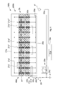
- FIG. 5 there is shown schematically a monitoring device 200b and thus an elevator system 100b in which a carrying and driving means 3b having twelve cords A1'-A6 'and B1'-B6' is used.
- the cords are divided into three groups of cords, which in turn are divided into two circuits.
- Amaschinetechniksmaschine 27a at a first end 43a 'of the supporting propellant 3b shows in contrast to a strictly alternating interconnection according to Fig.
- a contacting element 20a at a second end 43b 'of the carrying and driving means 3b comprises a preferably integrated switchable contacting device 29a in the form a time-demultiplexer that can time-controlled switch every single Cord A1'-A6 'and B1'-B6'.
- a test current IPb of a voltage source Ub grounded to a ground 24a is connected via a test circuit 23b and a switching device 31a, preferably also electronically and timed, to either the cord A1 'or the cord B1' and further to the cord A3 ', B3 'and the cords A5', B5 'can be applied.
- a current characteristic of the test current IPb at each individual Cord Al'-A6 'and B1'-B6' can be measured by a measuring device 25a and forwarded to an evaluation unit 32a with a preferably integrated computer 41a.
- the voltage source Ub is applied to the cord A3 'via the switching device 31a and the measuring device 25a detects a test current IPb at the cord A5', a cross-circuit between Cord A5 'and Cord A4' is established.
- Measuring signals from a contact point P 'can also pass directly to the evaluation unit 32a via a line 33a, but in principle can also be supplied to the measuring device 25a.
- the content of the examples can be combined.
- the 12 cords of the suspension according to Fig. 5 can be divided into two circuits to six cords or it can also be divided into two groups, each with two circuits to three cords. Also, as explained in section [0033], the ends of the cords in all the examples can be provided with specific resistances, whereby an even more accurate statement can be made about the state of the suspension element.
Landscapes
- Maintenance And Inspection Apparatuses For Elevators (AREA)
- Testing Of Devices, Machine Parts, Or Other Structures Thereof (AREA)
- Lift-Guide Devices, And Elevator Ropes And Cables (AREA)
Abstract
Description
Die vorliegende Erfindung betrifft eine Aufzugsanlage, bei der mindestens eine Aufzugskabine oder mindestens ein Fahrkorb und mindestens ein Gegengewicht in einem Aufzugsschacht gegenläufig bewegt werden, wobei die mindestens eine Aufzugskabine und das mindestens eine Gegengewicht an Führungsschienen entlanglaufen, von einem oder mehreren Trag-und Treibmitteln getragen und über eine Treibscheibe einer Antriebseinheit angetrieben werden. Die vorliegende Erfindung betrifft insbesondere das bzw. die Trag- und Treibmittel, nämlich ein Verfahren zur Überprüfung, bzw. Überwachung des oder der Trag- und Treibmittel der Aufzugsanlage und eine erfindungsgemässe Einrichtung zur Durchführung dieses Verfahrens.The present invention relates to an elevator installation, in which at least one elevator car or at least one counterweight is moved in opposite directions in an elevator shaft, wherein the at least one elevator car and the at least one counterweight run along guide rails, carried by one or more carrying and propelling means and driven by a traction sheave of a drive unit. The present invention relates in particular to the carrying and blowing agent, namely a method for checking or monitoring the carrying and blowing agent of the elevator installation and a device according to the invention for carrying out this method.
Bei Aufzugsanlagen hat sich die Verwendung von Trag-und Treibmitteln durchgesetzt, die aus mindestens einem Strom leitenden Stahlseil und nicht leitenden Ummantelungen bestehen oder aus Spezialkunststoffen gefertigten Seilen, in die ein Stromleiter eingearbeitet ist. Dadurch kann zur Überwachung des einzelnen tragenden Seiles oder der einzelnen tragenden Seile - auch Cords genannt - ein Prüfstrom angelegt werden. In dem so gebildeten Stromkreis oder in mehreren so gebildeten Stromkreisen wird der Stromfluss bzw. die Stromstärke, die Spannung, der elektrische Widerstand oder die elektrische Leitfähigkeit gemessen und gibt so Aufschluss über die Intaktheit bzw. den Abnützungsgrad des Trag- und Treibmittels.In elevator systems, the use of supporting and blowing agents has prevailed, which consist of at least one current-conducting steel cable and non-conductive sheaths or made of specialty plastics ropes, in which a conductor is incorporated. As a result, a test current can be applied for monitoring the individual supporting cable or the individual supporting cables - also called cords. In the circuit thus formed or in a plurality of circuits thus formed, the current flow or the current intensity, the voltage, the electrical resistance or the electrical conductivity is measured and thus provides information about the integrity or the degree of wear of the carrier and propellant.
So offenbart beispielsweise die Offenlegungsschrift
Das Patent
Die internationale Veröffentlichungsschrift
Eine weitere internationale Veröffentlichungsschrift
Eine europäische Veröffentlichungsschrift
Bei all diesen bekannten Überwachungen des Trag- und Treibmittels jedoch ist nachteilig, dass die Information über die Abnutzungserscheinung oder den vorliegenden Störfall des Trag- und Treibmittels durch den Zustand des Trag- und Treibmittels selbst verfälscht werden kann, wenn beispielsweise Querschlüsse zwischen einzelnen Cords, Schäden an der Ummantelung und Bruch eines Cords oder Teile davon in einer Kombination auftreten.In all these known monitoring of the carrying and blowing agent, however, is disadvantageous that the information about the wear or the present accident of the carrying and blowing agent can be falsified by the state of the support and propellant itself, for example, cross-circuits between individual cords, damage on the sheathing and breakage of a cord or parts of it in a combination occur.
In diesem Zusammenhang wird auf eine Patentanmeldung zur Überwachung eines Trag- und Treibmittels einer Aufzugsanlage der gleichen Anmelderin verwiesen, die am gleichen Tag eingereicht worden ist und deren Offenbarung in die vorliegende Patentanmeldung mit eingeschlossen ist. Dort wird eine Lösung vorgestellt, die eine genauere Diagnose eines Trag- und Treibmittels durch ein Verfahren und eine entsprechende Vorrichtung ermöglicht, indem an beiden Enden des Trag- und Treibmittels Kontaktierungselemente mit jeweils unterschiedlichen Widerständen an jedem einzelnem Cord vorgeschlagen werden.In this context, reference is made to a patent application for monitoring a carrying and propellant an elevator installation of the same applicant, the same day has been filed and the disclosure of which is included in the present patent application. There, a solution is presented, which allows a more accurate diagnosis of a carrying and propellant by a method and a corresponding device by proposed at both ends of the support and propellant contacting elements, each with different resistances on each cord.
Eine Aufgabe der vorliegenden Erfindung ist es, eine Überprüfungs-, bzw. eine Überwachungseinrichtung für Trag- und Treibmittel vorzuschlagen, die kostenoptimiert genauere bzw. qualitativ-klassifizierbare Informationen über den Zustand des Trag- und Treibmittels liefert und somit ein höheres Sicherheitsniveau für die Aufzugsanlage erreicht wird, bzw. kostenintensive zu frühe Auswechslungen des Trag- und Treibmittels vermieden werden.An object of the present invention is to propose a monitoring and monitoring device for carrying and propellant, the cost-optimized provides more accurate or qualitatively classifiable information about the state of the carrier and propellant and thus achieves a higher level of security for the elevator system is to be avoided or costly too early replacement of the carrier and propellant.
Die Lösung der Aufgabe besteht zunächst in der Anordnung eines Stromkreises, der grundsätzlich an ein einzelnes Ende eines Trag- und Treibmittels mit mindestens vier leitenden Cords anlegbar ist. Dieses erfolgt nur an einem Ende des Trag-und Treibmittels, vorzugsweise mittels eines hierfür vorgesehenen Kontaktierungselements. Am anderen Ende des Trag-und Treibmittels ist eine Kontaktierungsbrücke, bzw. eine Verschaltung vorgesehen, die die mindestens vier Cords des Trag-und Treibmittels zu einem ersten und einem zweiten Schaltkreis verbindet. Damit ist diese Ausführung besonders geeignet um in einer Aufzugsanlage mit direkt-, bzw. 1:1-aufgehängter Kabine und Gegengewicht verwendet zu sein, da hierbei die Kontaktbrücke beispielsweise am Aufhängepunkt des Gegengewichts angeordnet werden kann und die Kontaktierungselemente dementsprechend an der Kabine angeordnet wird. Somit muss lediglich die Kabine zum Zwecke der Kontaktierung zugänglich sein.The solution of the problem is initially in the arrangement of a circuit which is basically applied to a single end of a support and propellant with at least four conductive cords. This takes place only at one end of the carrying and blowing agent, preferably by means of a contacting element provided for this purpose. At the other end of the support and propellant a Kontaktierungsbrücke, or an interconnection is provided which connects the at least four cords of the support and propellant to a first and a second circuit. Thus, this embodiment is particularly suitable to be used in an elevator system with direct, or 1: 1 suspended cabin and counterweight, since in this case the contact bridge can be arranged for example at the suspension point of the counterweight and the contacting is accordingly arranged on the cabin. Thus, only the cabin needs to be accessible for the purpose of contacting.
Die Verbindung oder Verschaltung der in einer Reihe und parallel zueinander in einer gemeinsamen Ummantelung angeordneten Cords ist grundsätzlich so, dass jeder einzelne Cord des ersten Schaltkreises von mindestens einem Cord des zweiten Schaltkreises benachbart ist und jeder einzelne Cord des zweiten Schaltkreises von mindestens einem Cord des ersten Schaltkreises benachbart ist.The connection or interconnection of the in a row and parallel to each other in a common sheath arranged cords is basically such that each individual cord of the first circuit of at least one cord of the second circuit is adjacent and each individual cord of the second circuit of at least one cord of the first circuit is adjacent.
Dieses wiederum ergibt eine erste Ausgestaltungsvariante einer entsprechenden Verschaltung, bei der jeweils ein Cord des ersten Schaltkreises und jeweils ein Cord des zweiten Schaltkreises in abwechselnder Abfolge angeordnet sind. Mit anderen Wörtern, bilden die Cords eine Reihe, in der der erste Cord zum ersten Schaltkreis gehört und von einem zweiten Cord gefolgt ist, der Bestandteil des zweiten Schaltkreises ist. Dieser zweite Cord wiederum ist von einem dritten Cord gefolgt, der wiederum Bestandteil des ersten Schaltkreises ist. Dieser dritte Cord ist von einem vierten Cord gefolgt, der Bestandteil des zweiten Schaltkreises ist, usw. Es ergibt sich somit eine alternierende Anordnung, bei der die Rand-Cords von einem Cord des anderen Schaltkreises, und die restlichen Cords an beiden Seiten von je einem Cord des jeweilig anderen Schaltkreises benachbart sind.This in turn results in a first embodiment variant of a corresponding interconnection, in which in each case a cord of the first circuit and in each case a cord of the second circuit are arranged in an alternating sequence. In other words, the cords form a row in which the first cord belongs to the first circuit and is followed by a second cord that is part of the second circuit. This second cord, in turn, is followed by a third cord, which in turn is part of the first circuit. This third cord is followed by a fourth cord, which is part of the second circuit, etc. Thus, there is an alternating arrangement in which the edge cords of one cord of the other circuit, and the remaining cords on both sides of one Cord of the respective other circuit are adjacent.
Eine zweite Ausgestaltungsvariante einer Verschaltung ordnet die Cords so an, dass ebenfalls jeweils ein Cord eines Schaltkreises von einem Cord des anderen Schaltkreises benachbart ist, allerdings erfolgt dieses paarweise. Die Abfolge ist somit, wenn man beispielsweise von einem Trag- und Treibmittel mit acht Cords ausgeht und wenn man die Cords des ersten Schaltkreises mit A und diejenigen des zweiten Schaltkreises mit B bezeichnet, A1-B1-B2-A2-A3-B3-B4-A4. Bei der ersten Ausgestaltungsvariante der Verschaltung wäre sie hingegen A1-B1-A2-B2-A3-B3-A4-B4.A second embodiment of an interconnection arranges the cords so that in each case one cord of a circuit is adjacent to a cord of the other circuit, but this is done in pairs. The sequence is thus, for example, assuming a carrying and blowing agent with eight cords and when the cords of the first circuit with A and those of the second circuit with B, A1-B1-B2-A2-A3-B3-B4 -A4. In the first embodiment variant of the interconnection, however, it would be A1-B1-A2-B2-A3-B3-A4-B4.
Eine Basisvariante einer Anordnung sieht somit ein Trag- und Treibmittel vor, das mindestens vier leitende Cords aufweist. Dieses Trag- und Treibmittel ist im Wesentlichen ummantelt, weist jedoch an dem einem Ende das gemeinsame Kontaktierungselement bzw. an dem anderen Ende die Kontaktierungsbrücke auf, die jeweils mit den leitenden Cords in oben genannten Verschaltungen in Kontakt stehen. Dieses kann gewährleistet sein, indem die leitenden Cords an diesen Stellen von der Ummantelung befreit sind, oder das Kontaktierungselement bzw. die Kontaktierungsbrücke - vorzugsweise konkave Rillen ausformende - Kontaktflächen aufweisen, die mit Kontaktierungsnadeln die Ummantelung durchdringen.A basic variant of an arrangement thus provides a carrying and propellant having at least four conductive cords. This carrying and blowing agent is substantially encased, but has at the one end the common Contacting element or at the other end of the Kontaktierungsbrücke, which are in each case in contact with the conductive cords in the above-mentioned interconnections. This can be ensured by the conductive cords are freed from the sheath at these points, or have the contacting element or the Kontaktierungsbrücke - preferably concave grooves ausformende - contact surfaces which penetrate the sheathing with Kontaktierungsnadeln.
Kontaktierungselemente, wie sie grundsätzlich an dem einen Ende des Trag- und Treibmittels gemäss einer entsprechenden Überwachungseinrichtung Verwendung finden können, sind beispielsweise in der internationalen Anmeldung
Ein der Überwachungseinrichtung entsprechendes Kontaktierungselement ist vorzugsweise mit einer Kontaktierungsvorrichtung und diese wiederum vorzugsweise mit einer Auswerteeinheit verbunden, die in einem ersten Prüfungsschritt das Signal bzw. die massgebliche Strom-Kenngrösse oder auch mehrere massgebliche Strom-Kenngrössen an den Cords des ersten Schaltkreises auswertet und in einem nächsten, späteren Prüfungsschritt das Signal bzw. die massgebliche Strom-Kenngrösse oder auch mehrere massgebliche Strom-Kenngrössen an den Cords des zweiten Schaltkreises auswertet.A contacting element corresponding to the monitoring device is preferably connected to a contacting device and this in turn preferably connected to an evaluation unit, which evaluates the signal or the relevant current characteristic or several relevant current characteristics at the cords of the first circuit in a first test step and in one next, later test step evaluates the signal or the relevant current characteristic or several significant current characteristics at the cords of the second circuit.
Damit das Messen der Cords des ersten Schaltkreises in dem ersten Prüfungsschritt und in einem späteren, zweiten Prüfungsschritt das Messen der Cords des zweiten Schaltkreises erfolgen kann, ist die Kontaktierungsvorrichtung bzw. die mit ihr verbundene Auswerteeinheit schaltbar bzw. als ein Schieberegister ausgestaltet.In order for the measurement of the cords of the first circuit in the first test step and in a later, second test step, the measurement of the cords of the second circuit can take place, the contacting device or with their associated evaluation switchable or configured as a shift register.
Eine erste Ausgestaltungsvariante dieser schaltbaren Kontaktierungsvorrichtung funktioniert mechanisch und manuell. Hierfür weist sie eine Kontaktleiste mit Erhebungen und Vertiefungen auf, die nicht jedem benachbarten Cord, sondern nur jedem zweiten Cord innerhalb seiner parallelen Anordnung in dem Trag- und Treibmittel entsprechen. Die Erhebungen weisen vorzugsweise Kontaktnocken auf, die somit in einer ersten Kontaktposition der schaltbaren Kontaktierungsvorrichtung nur zu entsprechenden Kontaktflächen an den Cords des ersten Schaltkreises einen Kontakt herstellen. Nach einer Verstellung der Kontaktleiste, beispielsweise mittels eines Hebels und einem Führungsschlitten, bekommen die Kontaktnocken an den Erhebungen nur mit den Cords des zweiten Schaltkreises Kontakt.A first embodiment variant of this switchable contacting device works mechanically and manually. For this purpose, it has a contact strip with elevations and depressions, which correspond not every adjacent cord, but only every other cord within its parallel arrangement in the carrying and blowing agent. The elevations preferably have contact cams, which thus make contact in a first contact position of the switchable contacting device only to corresponding contact surfaces on the cords of the first circuit. After an adjustment of the contact strip, for example by means of a lever and a guide carriage, get the contact cam on the surveys only with the cords of the second circuit contact.
Eine zweite Ausgestaltungsvariante der schaltbaren Kontaktierungsvorrichtung weist nach wie vor die beschriebene Kontaktleiste innerhalb des Führungsschlittens auf, jedoch statt des manuell zu betätigenden Hebels ein elektromechanisches Stellglied, das vorzugsweise mittels einer Zeitsteuerung automatisch betätigt wird.A second embodiment of the switchable contacting device still has the described contact strip within the guide carriage, but instead of the manually operated lever, an electromechanical actuator, which is preferably actuated automatically by means of a timer.
Eine dritte Ausgestaltungsvariante der schaltbaren Kontaktierungsvorrichtung funktioniert rein elektronisch. Hierfür sind die Kontakte sowohl zu den Cords des ersten Schaltkreises, als auch zu den Cords des zweiten Schaltkreises physisch zwar existent, mit entsprechenden elektronischen Bauteilen - vorzugsweise auch wieder mittels einer automatischen Zeitsteuerung - so öffen- und schliessbar, dass das Messen gemäss des ersten Prüfungsschritts und anschliessend das Messen gemäss des zweiten Prüfungsschritts erfolgen kann. Grundsätzlich sind solche elektronischen Schaltvorrichtungen bzw. elektronischen Schieberegister bzw. sogenannte Demultiplexer oder Zeit-Demultiplexer einem Fachmann bekannt und somit nicht Gegenstand einer Beschreibung innerhalb dieser Patentanmeldung.A third embodiment variant of the switchable contacting device works purely electronically. For this purpose, the contacts to both the cords of the first circuit, as well as the cords of the second circuit physically exist, with appropriate electronic components - preferably again by means of an automatic timing - so openable and closable that the measuring according to the first test step and then the measuring according to the second test step can be done. Basically, such electronic switching devices or electronic shift registers or so-called demultiplexer or time-demultiplexer known to a person skilled in the art and thus not Subject of a description within this patent application.
Die Kontaktierungsbrücke an dem anderen Ende des Trag- und Treibmittels stellt den Kontakt zwischen den Cords des ersten Schaltkreises einerseits und andererseits zwischen den Cords des zweiten Schaltkreises her. Hierfür umfasst die Kontaktierungsbrücke vorzugsweise zwei Kontaktplatten auf, die vorzugsweise die entsprechenden und entsprechend von der Ummantelung befreiten Cords mit konkavförmigen Rillen umschliessen. Zwischen den Kontaktplatten ist eine dritte, isolierende Zwischenplatte angeordnet und alle drei Platten werden beispielsweise mit Schraubverbindungen gefasst; die leitenden Cords hierbei einklemmend. Die Schraubverbindungen sind vorzugsweise durch isolierte Bohrungen geführt und mit isolierenden Scheiben unterlegt, sodass kein elektrischer Kontakt zwischen der ersten und der zweiten Kontaktplatte möglich ist.The Kontaktierungsbrücke at the other end of the carrying and blowing means establishes the contact between the cords of the first circuit on the one hand and on the other hand between the cords of the second circuit. For this purpose, the contacting bridge preferably comprises two contact plates, which preferably enclose the corresponding cords, which have been removed correspondingly from the casing, with concave grooves. Between the contact plates, a third, insulating intermediate plate is arranged and all three plates are taken, for example, with screw; Clamping the leading cords here. The screw connections are preferably guided through insulated bores and underlaid with insulating discs, so that no electrical contact between the first and the second contact plate is possible.
Eine weitere Ausgestaltungsvariante einer Kontaktierungsbrücke sieht vor, dass die leitenden Cords nicht von ihrer Ummantelung befreit werden und die vorzugsweise konkavförmigen Rillen in den Kontaktplatten Kontaktnadeln aufweisen, die die Ummantelung der entsprechenden Cords durchstechen. In diesem Fall dient die Ummantelung des Trag- und Treibmittels als Isolator, sodass auf die dritte, isolierende Zwischenplatte verzichtet werden kann.A further embodiment variant of a Kontaktierungsbrücke provides that the conductive cords are not freed from their sheath and the preferably concave grooves in the contact plates have contact pins which pierce the sheath of the corresponding cords. In this case, the sheathing of the carrying and propellant acts as an insulator, so that it is possible to dispense with the third, insulating intermediate plate.
Die Kontaktplatten beider Ausgestaltungsvarianten sind vorzugsweise breiter als das Trag- und Treibmittel, sodass eine Anbringung an dem Ende des Trag- und Treibmittels jenseits, aber auch diesseits des Befestigungspunktes des Trag- und Treibmittels im Schacht, an dem Gegengewicht oder an der Aufzugskabine möglich ist.The contact plates of both embodiments are preferably wider than the support and propellant, so that attachment to the end of the support and propellant beyond, but also this side of the attachment point of the support and propellant in the shaft, on the counterweight or on the elevator car is possible.
Eine Überwachungseinrichtung umfasst des Weiteren mindestens eine Spannungsquelle, die an das Trag- und Treibmittel anschliessbar ist und einen dem Zustand des Trag-und Treibmittel entsprechenden Prüfstrom bewirkt. Gemäss einer ersten Ausgestaltungsvariante diesbezüglich ist eine erste Spannungsquelle entsprechend einem ersten Prüfstrom an ein Cord des ersten Schaltkreises und eine zweite Spannungsquelle mit einer zweiten, vorzugsweise von der ersten Spannungsquelle unterschiedlicher Charakteristik an ein Cord des zweiten Schaltkreises anlegbar.A monitoring device further comprises at least one voltage source, which is connectable to the support and propellant and a the state of the support and Propellant corresponding test current causes. According to a first embodiment variant in this regard, a first voltage source corresponding to a first test current to a cord of the first circuit and a second voltage source with a second, preferably different from the first voltage source characteristic to a cord of the second circuit can be applied.
Die zwei Spannungsquellen sind nicht zwingend, jedoch vorzugsweise bei Bedarf manuell oder mittels einer Zeitsteuerung automatisch ein- und abschaltbar.The two voltage sources are not mandatory, but preferably automatically switched on and off manually if necessary or by means of a timer.
Des Weiteren ist es jedoch auch möglich, eine einzige Spannungsquelle und dementsprechend einen einzigen Prüfstrom vorzusehen, wobei die Spannungsquelle mittels einer Schaltvorrichtung in eine erste und eine zweite Schaltposition schaltbar ist. In der ersten Schaltposition ist der Prüfstrom an ein Cord oder an die Kontaktplatte des ersten Schaltkreises, und in der zweiten Schaltposition an ein Cord oder an die Kontaktplatte des zweiten Schaltkreises anlegbar.Furthermore, however, it is also possible to provide a single voltage source and, accordingly, a single test current, wherein the voltage source can be switched by means of a switching device into a first and a second switching position. In the first switching position, the test current can be applied to a cord or to the contact plate of the first circuit, and in the second switching position to a cord or to the contact plate of the second circuit.
Diese Schaltvorrichtung für die Spannungsquelle kann ebenfalls - wie die schaltbare Kontaktierungsvorrichtung - manuell bedienbar ausgestaltet sein. Eine elektromechanische Ausgestaltungsvariante hiervon ist vorzugsweise zeitgesteuert automatisch und mit der dann ebenfalls elektromechanisch schaltbaren Kontaktierungsvorrichtung so gekoppelt, dass bei jedem zweiten Umschalten der Letzteren die Schaltvorrichtung der Spannungsquelle mitschaltet. Des Weiteren ist die Schaltvorrichtung der Spannungsquelle auch rein elektronisch realisierbar und vorzugsweise mit einer dann ebenfalls rein elektronischen Ausgestaltungsvariante der schaltbaren Kontaktierungsvorrichtung gekoppelt.This switching device for the voltage source can also - like the switchable contacting device - be designed to be manually operated. An electromechanical embodiment variant thereof is preferably timed automatically and coupled with the then also electromechanically switchable contacting device so that every other switching of the latter, the switching device of the voltage source mitschaltet. Furthermore, the switching device of the voltage source can also be implemented purely electronically and is preferably coupled to a likewise purely electronic configuration variant of the switchable contacting device.
Als jeweilige Schadensereignisse kommen, wie schon erwähnt, folgende Fälle in Betracht: Cordbruch, Querschluss (Kurzschluss zwischen zwei Cords) oder beides zusammen. Diese Schadensereignisse sind mit einer wie bisher beschriebenen Überwachungseinrichtung im folgenden Prüfvorgang ermittelbar.As already mentioned, the following cases can be considered as damage incidents: cord break, short circuit (short circuit between two cords) or both together. These Damage events can be determined with a monitoring device as described so far in the following test procedure.
In einem ersten Prüfungsschritt wird an einen Cord - normalerweise an den ersten Rand-Cord - des ersten Schaltkreises die Spannungsquelle angelegt. An allen anderen Cords dieses ersten Schaltkreises wird geprüft, ob ein Signal ankommt bzw. ein entsprechender Prüfstrom bzw. eine seiner Strom-Kenngrössen messbar ist. Ist dieses bei einem Cord des ersten Schaltkreises nicht der Fall, so ist dieser Cord gebrochen. Wenn der Prüfstrom hingegen auf gar keinem der Cords des ersten Schaltkreises messbar ist, so ist derjenige Cord gebrochen, an den der Prüfstrom angelegt worden ist - beispielsweise der erste Rand-Cord. Anschliessend wird mittels eines Umschaltens der schaltbaren Kontaktierungsvorrichtung die Kontaktposition des Kontaktierungselements bzw. der damit verbundenen Auswerteeinheit von der ersten Kontaktposition zu den Cords des ersten Schaltkreises auf die zweite Kontaktposition zu den Cords des zweiten Schaltkreises gewechselt. An diesen Cords des zweiten Schaltkreises ist vorliegend keine Spannung angelegt, wenn jedoch trotzdem eine Strom-Kenngrösse messbar ist, so besteht zwischen den betroffenen Cords und einem oder mehreren benachbarten Cords ein Kurzschluss.In a first test step, the voltage source is applied to a cord, usually the first edge cord, of the first circuit. On all other cords of this first circuit it is checked whether a signal arrives or a corresponding test current or one of its current characteristics can be measured. If this is not the case with a cord of the first circuit, then this cord is broken. On the other hand, if the test current can not be measured on any of the cords of the first circuit, then the one to which the test current has been applied is broken - for example, the first edge cord. Subsequently, the contact position of the contacting element or the evaluation unit connected thereto is changed from the first contact position to the cords of the first circuit to the second contact position to the cords of the second circuit by means of a switching of the switchable contacting device. In the present case, no voltage is applied to these cords of the second circuit, but if a current characteristic can still be measured, there is a short circuit between the cords concerned and one or more adjacent cords.
In einem zweiten Prüfungsschritt wird das Anlegen der Spannungsquelle an einen Cord des ersten Schaltkreises zu einem Anlegen der Spannungsquelle an einen Cord des zweiten Schaltkreises gewechselt. Dieses kann beispielsweise an dem zweiten Cord oder - bei gerader Gesamtanzahl von Cords - an dem zweiten Rand-Cord erfolgen, der dem ersten Rand-Cord an der anderen Seite des Trag- und Treibmittels gegenüberliegt. Nun wird analog zum ersten Prüfungsschritt an allen Cords des zweiten Schaltkreises geprüft, ob der Prüfstrom messbar ist. Ist dieses an einem Cord des zweiten Schaltkreises nicht der Fall, so ist dieser Cord gebrochen. Ist der Prüfstrom an gar keinem Cord des zweiten Schaltkreises messbar, so ist derjenige Cord gebrochen, an den der Prüfstrom angelegt worden ist, beispielsweise der zweite Cord oder der zweite Rand-Cord. Anschliessend wird, vorzugsweise ebenfalls mit der beschriebenen schaltbaren Kontaktierungsvorrichtung, die nun vorliegende Kontaktposition zu den Cords des zweiten Schaltkreises zu der Kontaktposition zu den Cords des ersten Schaltkreises zurückgewechselt und analog zu dem ersten Prüfungsschritt ermittelt, ob ein Kurzschluss vorliegt.In a second test step, the application of the voltage source to a cord of the first circuit is switched to applying the voltage source to a cord of the second circuit. This may be done, for example, on the second cord or, with an even total number of cords, on the second edge cord opposite the first edge cord on the other side of the support and propellant. Now, as in the first test step, it is checked on all cords of the second circuit whether the test current can be measured. If this is not the case on a cord of the second circuit, then this cord is broken. If the test current can not be measured at any cord of the second circuit, then that cord is broken, to which the test current has been applied, for example, the second cord or the second edge cord. Subsequently, preferably also with the described switchable contacting device, the now present contact position is switched back to the cords of the second circuit to the contact position to the cords of the first circuit and determined analogously to the first test step, if there is a short circuit.
Selbstverständlich ist es möglich, die Messungen an den Cords nicht nur mit der beschriebenen schaltbaren Kontaktierungsvorrichtung, sondern auch einzeln an jedem Cord vorzunehmen, die kumulierte und automatisierte Messung bringt jedoch Vorteile hinsichtlich einer raschen Diagnose bzw. einer kurzen Überprüfungsdauer und somit nur kurzen Stillstandzeit der Aufzugsanlage, sofern es vorgesehen ist, dass die Überprüfung nicht auch während ihrem Betrieb stattfinden kann.Of course, it is possible to make the measurements on the cords not only with the described switchable contacting device, but also individually on each cord, but the cumulative and automated measurement has advantages in terms of a quick diagnosis or a short test period and thus only short downtime of the elevator system provided that it is foreseen that the verification can not take place during its operation.
Eine weiterführende Ausgestaltung sieht vor, dass der vorgenannte erste Prüfungsschritt und der folgende zweite Prüfungsschritt in der weiteren Folge für alle übrigen Cords wiederholt werden. Damit wird eine Aussagefähigkeit über den Zustand des Tragmittels weiter verbessert. Zudem kann unter Verwendung von spezifischen Kennwiderständen, welche beispielsweise in die Verbindungen der Cords bei der Kontaktierungsbrücke integriert sein können - wie es in der parallelen Anmeldung zur Überwachung eines Trag- und Treibmittels offenbart ist -, eine weitere Verbesserung der Diagnose zum Zustand des Tragmittels erreicht werden. In dieser parallelen Anmeldung ist offenbart, dass an jedem Ende eines Cords des Trag- und Treibriemens ein bestimmter Kennwiderstand angeordnet ist. Unter Anwendung dieser Lehre kann nun mit der vorliegenden Überwachungseinrichtung anhand eines festgestellten Widerstands, bzw. dem entsprechenden Prüfstrom, präziser festgestellt werden wo beispielsweise ein Querschluss zwischen Cords vorliegt.A further embodiment provides that the aforementioned first test step and the following second test step are repeated in the further sequence for all remaining cords. This further enhances informative value about the condition of the suspension element. In addition, by using specific characteristic resistors, which may for example be integrated into the connections of the cords in the contacting bridge - as disclosed in the parallel application for monitoring a carrier and propellant -, a further improvement in the diagnosis of the condition of the suspension element can be achieved , In this co-pending application it is disclosed that at each end of a cord of the support and drive belt a certain characteristic resistor is arranged. Using this teaching can now be determined more precisely with the present monitoring device based on a detected resistance, or the corresponding test current, where, for example, a cross-circuit between cords is present.
Quasi in einem dritten Prüfungsschritt findet die Auswertung der Messergebnisse aus dem ersten und dem zweiten Prüfungsschritt mittels einer Auswerteeinheit statt. Diese Auswerteeinheit weist vorzugsweise einen Computer auf, der einerseits in der Lage ist, das Messergebnis des ersten Prüfungsschrittes mit dem Messergebnis des zweiten Prüfungsschrittes zu vergleichen und somit festzustellen, welche Cords Querschluss zueinander haben. Andererseits ist der Computer aufgrund eingegebener Referenzwerte in der Lage, eine Freigabe-Meldung oder eine - vorzugsweise gestaffelte - Warnmeldung auszugeben oder - vorzugsweise über eine Koppelung an einen Computer der Aufzugssteuerung - den Betrieb der Aufzugsanlage zu stoppen.Quasi in a third test step, the evaluation of the measurement results from the first and the second test step by means of an evaluation takes place. This evaluation unit preferably has a computer, which on the one hand is able to compare the measurement result of the first test step with the measurement result of the second test step and thus determine which cords have cross-connection to each other. On the other hand, based on input reference values, the computer is able to issue a release message or a - preferably staggered - warning message or - preferably via a coupling to a computer of the elevator control - to stop the operation of the elevator installation.
In einer vorzugsweisen Ausgestaltung sind jeweils - bei einem Trag- und Treibriemen mit vielen Cords Vierergruppen gebildet und die Cords dieser Gruppen sind zu jeweils zwei Schaltkreisen, wie vorgängig erläutert zusammen geschalten und ausgewertet. Somit lässt sich eine genaue Lokalisierung der diagnostizierten Schäden vornehmen.In a preferred embodiment are each - formed in a support and drive belt with many cords four groups and the cords of these groups are connected to two circuits, as previously explained together and evaluated. Thus, a precise localization of the diagnosed damage can be made.
Hinsichtlich der erwähnten Referenzwerte ist es bevorzugt, einen Betrieb der Aufzugsanlage mit einem gebrochenen Cord nicht zuzulassen und die zulässige Anzahl von Querschlüssen auf eine bestimmte Anzahl zu begrenzen. Eine zu hohe Anzahl von Querschlüssen kann nämlich ein so hohes Mass an ungehindertem Kontakt bzw. Stromfluss zwischen den Cords bewirken, das die eindeutige Detektion eines Cordbruchs verwässert.With regard to the mentioned reference values, it is preferable not to allow operation of the elevator installation with a broken cord and to limit the permissible number of cross-connections to a certain number. Too high a number of cross-overs can cause such a high level of unimpeded contact or current flow between the cords, which dilutes the unambiguous detection of a cord breakage.
Ein weiterer Kontaktpunkt des jeweiligen Prüf-Stromkreises - sei es den ersten oder den zweiten Schaltkreis der jeweiligen Cords umfassend - kann an einem oder mehreren Punkten angeordnet sein, an dem bzw. an denen das Trag- und Treibmittel beim Betrieb vorbeiläuft.Another contact point of the respective test circuit - be it the first or the second circuit of the respective cords comprising - can be arranged at one or more points at which or on which the carrying and blowing agent passes during operation.
Dieser Punkt kann beispielsweise eine beliebige Umlenkrolle sein, sei es eine ortsfest in dem Aufzugsschacht angeordnete Umlenkrolle oder aber auch die oder eine der Umlenkrollen des Gegengewichts oder der Aufzugskabine. Als Punkt, an dem das Trag- und Treibmittel vorbeiläuft, kommt jedoch auch ein sogenannter Retainer, d.h. ein Entgleisungsschutz in Betracht, den Umlenkrollen üblicherweise aufweisen. Aber auch Tragrollen des Gegengewichts oder der Aufzugskabine und grundsätzlich auch die Treibscheibe sowie metallische Schachtkomponenten kommen in Betracht. Wesentlich ist nur, dass der Punkt leitend ist und geerdet werden kann - im Falle des Betreibens der Überwachungseinrichtung mit Gleichstrom - bzw. eine Spannung an den Punkt anlegbar ist - im Falle des Betreibens der Überwachungseinrichtung mit Wechselstrom - und grundsätzlich ein Kontakt zu dem leitenden Teil oder den leitenden Teilen eines Trag- und Treibmittels möglich ist.This point can, for example, be an arbitrary deflection roller, be it a stationary one in the elevator shaft arranged deflection roller or else the or one of the deflection rollers of the counterweight or the elevator car. However, as a point at which the carrying and blowing agent passes, there is also a so-called retainer, ie a derailment protection, which the deflection rollers usually have. But also support rollers of the counterweight or the elevator car and in principle also the traction sheave and metallic shaft components come into consideration. It is essential only that the point is conductive and can be grounded - in the case of operating the monitoring device with DC - or a voltage can be applied to the point - in the case of operating the monitoring device with AC - and in principle a contact with the conductive part or the conductive parts of a carrier and propellant is possible.
Dieser letztgenannte Kontakt zwischen dem Punkt, beispielsweise der Umlenkrolle, und dem leitenden Teil oder den leitenden Teilen des Trag- und Treibmittels kann realisiert sein, indem beispielsweise die leitenden Cords des Trag- und Treibmittels nicht komplett, sondern eben nur im Wesentlichen mit nicht leitendem Kunststoff ummantelt ist. Es bleiben aneinandergereihte leitende Stellen frei oder auch ganze freie Teile des Querschnittsumfangs, die sich über die gesamte Abwicklungslänge des Trag- und Treibmittels erstrecken und mit der Umlenkrolle in elektrischem Kontakt stehen können. Eine weitere Möglichkeit, den Kontakt zwischen den Cords und der Umlenkrolle bzw. dem Punkt mit dem dritten Widerstand herzustellen, ist die Einarbeitung von leitenden Litzen in die Ummantelung des Trag- und Treibmittels. Grundsätzlich ist auch ein Trag- und Treibmittel mit einer leitenden Ummantelung möglich, das aber dann vorzugsweise eine Isolationsschicht zwischen dem leitenden Cord und der leitenden Ummantelung aufweist.This latter contact between the point, for example, the guide roller, and the conductive part or the conductive parts of the support and propellant can be realized, for example, the conductive cords of the support and propellant not completely, but only substantially with non-conductive plastic is sheathed. There remain juxtaposed conductive points or even entire free parts of the cross-sectional circumference, which extend over the entire unwinding length of the support and propellant and can be in electrical contact with the deflection roller. Another way to make the contact between the cords and the pulley or the point with the third resistor is the incorporation of conductive strands in the sheath of the support and propellant. In principle, a carrying and blowing agent with a conductive sheath is possible, but then preferably has an insulating layer between the conductive cord and the conductive sheath.
Grundsätzlich jedoch ist bei einer Überwachungseinrichtung auch eine Anordnung möglich, bei der Stromfluss zu diesem zusätzlichen Kontaktpunkt oder zu mehreren zusätzlichen Kontaktpunkten nur dann entsteht, wenn die Ummantelung eines Cords, beispielsweise bei einem Querschluss oder aber auch bei einem Cordbruch, so beschädigt ist, dass einzelne Litzen des Cords heraustreten. Wenn nun alle anderen Rollen, über die das Trag- und Treibmittel läuft, geerdet sind, so detektiert beispielsweise ein FI-Schalter, der an den Kontaktpunkt angeschlossen ist, somit diese Beschädigung und liefert eine Information darüber, an welcher Stelle innerhalb der Gesamtlänge des Cords sie sich befindet.In principle, however, an arrangement is also possible with a monitoring device in which current flows to this additional contact point or to several Additional contact points only arises when the sheath of a cord, for example, in a cross-circuit or even in a cord breakage, is so damaged that individual strands of the cord emerge. Thus, if all the other rollers that carry and carry the propellant are grounded, for example, an RCD connected to the point of contact will detect this damage and provide information about where in the entire length of the cord she is.
Somit sind die Cords derart mit Spannungsquellen verschaltet, dass sich abhängig von der jeweiligen Fehlermöglichkeit bestimmte Gesamtwiderstände, Stromstärken oder - bei konstant gehaltener Spannungsquelle - spezifische Spannungen an den Messpunkten ergeben. Die jeweils ermittelten Messwerte lassen sich dabei eindeutig einem jeweiligen Schadensereignis zuordnen. Die Messung kann sowohl permanent, als auch in Intervallen oder nur bei Bedarf vor und/oder während jeder Fahrt als entsprechende Bedingung für eine Fahrtfreigabe abgefragt werden.The cords are thus connected to voltage sources in such a way that specific total resistances, current intensities or-given a constant voltage source-specific voltages at the measuring points result, depending on the respective failure mode. The respective measured values can be clearly assigned to a respective damage event. The measurement can be queried both permanently and at intervals or only as needed before and / or during each trip as a corresponding condition for a ride release.
Vorzugsweise erfolgt die Erfassung bzw. die Berechnung der beschriebenen Messwerte computerunterstützt und automatisch und ist auf einem Display oder Monitor anzeigbar. Der Computer der Auswerteeinheit ist vorzugsweise des Weiteren in der Lage, die Auftritte von Schäden zu speichern und somit ein Schadenshäufungs-Bild zu erstellen.Preferably, the detection or the calculation of the measured values described is computer-assisted and automatic and can be displayed on a display or monitor. The computer of the evaluation unit is preferably further able to save the occurrence of damage and thus to create a damage cluster image.
Insbesondere bei einer Überwachungseinrichtung für ein Trag- und Treibmittel mit einer relativ hohen Anzahl mehrerer Cords ist es möglich, ebenfalls vorzugsweise mittels des unterstützenden Computers, das Schadensausmass bzw. den Zustand des gesamten Trag- und Treibmittels im Hinblick auf die Anzahl von schadhaften Stellen und im Hinblick auf das Ausmass einer jeweiligen einzelnen schadhaften Stelle zu bewerten und somit eine gestaffelte Warnmeldung auszugeben. So ist beispielsweise realisierbar, dass ein Trag- und Treibmittel mit beispielsweise 12 Cords, bei denen nur selten und mit geringer Intensität ein Querschluss auftritt, noch bedenkenlos eine bestimmte Zeit benützt werden kann. Diese bestimmte Karenz-Zeit wird von dem Computer erfasst und nochmals verkürzt oder führt zu einem Stillstand der Aufzugsanlage, wenn sich das Schadensausmass entsprechend ausweiten sollte bzw. ein weiteres Schadensereignis hinzukommen sollte. Beim genannten Beispiel mit 12 Cords kann durch eine vorgängig beschriebene Aufteilung auf drei Gruppen zu jeweils vier Cords, welche dann auf jeweils zwei Schaltkreise aufgeteilt sind, eine genauere Aussage zum Zustand des Trag- und Treibmittels gemacht werden.In particular, in a monitoring device for a support and propellant with a relatively high number of multiple cords, it is also possible, preferably by means of the supporting computer, the extent of damage or the state of the entire support and propellant in terms of the number of damaged areas and in the To assess the extent of each individual damaged site and thus issue a staggered warning message. For example, it can be realized that a carrier and propellant with For example, 12 cords, in which only rarely and with low intensity occurs a cross-circuit, can still be safely used for a certain time. This certain waiting period is recorded by the computer and shortened again or leads to a shutdown of the elevator system, if the extent of the damage should expand accordingly or another damage event should be added. In the example given with 12 cords can be made by a previously described division into three groups of four cords, which are then divided into two circuits, a more accurate statement on the condition of the carrying and propellant.
Zur Vermeidung einer Verfälschung der Messungen, die kontinuierlich, also auch bei Stillstand der Aufzugsanlage, nur während einer Fahrt oder/und vor einer Fahrt erfolgen können, ist es vorgesehen, statische Aufladungen der Aufzugsanlage ständig oder zumindest vor dem Erfolgen einer Messung durch eine Erdung abzuleiten.In order to avoid a falsification of the measurements, which can take place continuously, ie even when the elevator installation is stationary, only during a journey and / or before a journey, it is provided to discharge static charges of the elevator installation continuously or at least before a measurement is carried out by a grounding ,
Die offenbarten Ausgestaltungsvarianten einer Überwachungseinrichtung sind vorzugsweise mit einem Biegewechselzähler kombinierbar, sodass eine weitere Information in - die vorzugsweise computerunterstütze - Überwachungseinrichtung einfliesst und somit die Ermittlung der Ablegereife eines Trag- und Treibmittels noch zuverlässiger wird.The disclosed embodiments of a monitoring device can preferably be combined with a flexible counter, so that further information flows into the monitoring device, which is preferably computer-assisted, and thus the determination of the ability to discard a carrier and propellant becomes even more reliable.
Die Messung kann sich auf die folgenden Strom-Kenngrössen beziehen: auf den Widerstand oder/und auf eine Widerstands-Kenngrösse, auf die Stromstärke, auf die Spannung, auf die Frequenz, auf die Induktivität, auf die Kapazität oder auf Kombinationen hiervon.The measurement may relate to the following current characteristics: resistance and / or a resistance characteristic, current, voltage, frequency, inductance, capacitance or combinations thereof.
Zusammenfassend ergibt eine erfindungsgemässe Überwachungseinrichtung die folgenden Vorteile:
- Die Messwerte sind im Gegensatz zu einer einfachen Durchgangsprüfung quantifizier- und qualifizierbar und somit sind präzisere und gestaffelte Warnmeldungen generierbar.
- Es ist ein Schadenshäufungs-Bild erstellbar.
- Die Messwerte sind weitgehend unabhängig von dem spezifischen Widerstand eines Cords.
- Trotz dem Vorliegen eines allfälligen Querschlusses bleibt ein Cordbruch erkennbar.
- Es ist nur eine einseitige Anschlussstelle durch ein entsprechendes Kontaktierungselement erforderlich.
- In contrast to a simple continuity test, the measured values can be quantified and qualified and thus more precise and staggered warning messages can be generated.
- It is a damage accumulation image buildable.
- The measurements are largely independent of the resistivity of a cord.
- Despite the presence of a possible cross-circuit a cord break remains recognizable.
- It is only a one-sided connection point required by a corresponding contacting element.
Über die Überprüfung eines Trag- und Treibmittels mittels einer derartigen Überwachungseinrichtung hinaus werden weitere zusätzliche Bewertungskriterien für den Zustand des Trag- und Treibmittels herangezogen. So werden neben der beschriebenen elektrischen Messung und dem beschriebenen Biegewechselzähler beispielsweise auch eine reine Fahrtenzählung, Sensoren für die Schlaffheit des Trag- und Treibmittels, magnetische Messungen, Ultraschall-Messungen, Radiographien, visuelle Kontrollen oder aber auch einfach nur das Alter des Trag- und Treibmittels als Bewertungskriterium verwendet.Beyond the verification of a carrying and propellant means of such a monitoring device addition further evaluation criteria for the condition of the carrying and propellant be used. Thus, in addition to the described electrical measurement and the described Biegewechselzähler example, a pure driving count, sensors for the slack of the carrier and propellant, magnetic measurements, ultrasound measurements, radiographs, visual controls or just simply the age of the carrier and propellant used as an evaluation criterion.
Im Rahmen der Offenbarung der vorliegenden Anmeldung liegt ein Überwachungssystem, zu dem die vorgängig erläuterte Überwachungseinrichtung lediglich einen Bestandteil darstellt und weitere, beispielhaft oben aufgeführte Bewertungskriterien in den Computer der Auswerteeinheit oder einen anderweitigen Computer der Aufzugsanlage einfliessen. Hierbei sei erwähnt, dass eine Überwachung eines Trag- und Treibmittels in der Regel mehrere Teilüberwachungen enthält. So erfolgen beispielsweise kontinuierliche Überwachungen, wie sie vorgängig beschrieben sind. In bestimmten Abständen erfolgen üblicherweise visuelle Kontrollen zur Feststellung äusserer Schäden und abhängig einer Betriebsdauer (Anzahl Fahrten, etc.) erfolgen Detailkontrollen beispielsweise mittels Durchstrahlung oder magnetinduktiven Prüfverfahren. Vielfach sind auch Zeitkriterien zur Bestimmung des Zustands des Trag- und Treibriemens mitberücksichtigt, wenn beispielsweise eine alterungsbedingte Versprödung einer Ummantelung zu erwarten ist. Eine Auswahl oder Bestimmung der erforderlichen Kontrollen erfolgt in der Regel abhängig von der Art der Aufzugsanlage, wobei Last, Betriebzyklen, Häufigkeit der Benutzung, äussere Bedingungen, etc. mitberücksichtigt werden. Der vorgenannte Computer ist vorzugsweise einerseits in der Lage, sämtliche Bewertungskriterien kumuliert zu berücksichtigen und andererseits eine entsprechende Freigabe-Meldung, eine Service-Anzeige, ein Stopp-Signal, aber auch eine Information über den Ist-Zustand des Trag- und Treibmittels auszugeben, sowie eine Meldung an den Eigentümer bzw. die Servicefirma abzusetzen.In the context of the disclosure of the present application is a monitoring system to which the previously explained monitoring device is only one part and further, listed by way of example above evaluation criteria in the computer of the evaluation or an other computer of the elevator system flow. It should be noted that monitoring of a carrying and propellant usually contains several partial monitoring. For example, continuous monitoring, as described above, takes place. At certain intervals, visual checks are usually carried out to determine external damage and, depending on a period of operation (number of trips, etc.), detailed checks are carried out, for example by means of transmission or magnetic-inductive test methods. In many cases there are also time criteria for the determination the state of the support belt and drive belt taken into account, for example, if an aging-related embrittlement of a jacket is to be expected. A selection or determination of the required checks is usually made depending on the type of elevator installation, taking into account load, operating cycles, frequency of use, external conditions, etc. The aforementioned computer is preferably on the one hand in a position to cumulatively take into account all evaluation criteria and on the other hand to issue a corresponding release message, a service indicator, a stop signal, but also information about the actual state of the carrier and propellant, as well send a message to the owner or service company.
Weitere oder vorteilhafte Ausgestaltungen einer Überwachungseinrichtung für ein Trag- und Treibmittel in einer Aufzugsanlage bilden die Gegenstände der abhängigen Ansprüche.Further or advantageous embodiments of a monitoring device for a carrier and propellant in an elevator system form the subject of the dependent claims.
Anhand von Figuren wird die Erfindung symbolisch und beispielhaft näher erläutert. Die Figuren werden zusammenhängend und übergreifend beschrieben. Gleiche Bezugszeichen bedeuten gleiche Bauteile, Bezugszeichen mit unterschiedlichen Indices geben funktionsgleiche oder ähnliche Bauteile an.The invention will be explained symbolically and by way of example with reference to figures. The figures are described coherently and comprehensively. The same reference symbols denote the same components, reference symbols with different indices indicate functionally identical or similar components.
Es zeigen dabei:
- Fig. 1
- eine schematische Darstellung einer beispielhaften Aufzugsanlage mit einer Überwachungseinrichtung für das Trag- und Treibmittel gemäss Stand der Technik;
- Fig. 2
- eine schematische Darstellung einer ersten Ausgestaltungsvariante einer Überwachungseinrichtung für ein Trag- und Treibmittel mit vier Cords;
- Fig. 3
- eine schematische Darstellung der Führung des Trag- und Treibmittels über ein Eck einer Aufzugskabine, bei gleichzeitiger Darstellung eines Cordbruchs und eines Querschlusses;
- Fig. 4
- eine schematische Darstellung einer Ausgestaltungsvariante einer Kontaktierungsbrücke und
- Fig. 5
- eine schematische Darstellung einer zweiten Ausgestaltungsvariante einer Überwachungseinrichtung für das Trag- und Treibmittel.
- Fig. 1
- a schematic representation of an exemplary elevator system with a monitoring device for the supporting and blowing agent according to the prior art;
- Fig. 2
- a schematic representation of a first embodiment variant of a monitoring device for a supporting and blowing agent with four cords;
- Fig. 3
- a schematic representation of the leadership of the carrying and propellant over a corner of an elevator car, while displaying a cord breakage and a cross-circuit;
- Fig. 4
- a schematic representation of an embodiment variant of a Kontaktierungsbrücke and
- Fig. 5
- a schematic representation of a second embodiment variant of a monitoring device for the support and propellant.
Die
Die Aufzugskabine 2 kann auf einer Förderhöhe h eine oberste Stockwerktüre 8, weitere Stockwerktüren 9 und 10 und eine unterste Stockwerktüre 11 bedienen. Der Aufzugsschacht 1 ist aus Schacht-Seitenwänden 15a und 15b, einer Schachtdecke 13 und einem Schachtboden 14 gebildet, auf dem ein Schachtbodenpuffer 19a für das Gegengewicht 4 und zwei Schachtbodenpuffer 19b und 19c für die Aufzugskabine 2 angeordnet sind.The
Das Trag- und Treibmittel 3 ist an einem ortsfesten Befestigungspunkt bzw. Tragmittelfixpunkt 16a an der Schachtdecke 13 befestigt und parallel zu der Schacht-Seitenwand 15a zu einer Tragrolle 17 für das Gegengewicht 4 geführt. Von hier wiederum zurück über die Treibscheibe 5, zu einer ersten Umlenk- bzw. Tragrolle 18a und einer zweiten Umlenk- bzw. Tragrolle 18b, die Aufzugskabine 2 unterschlingend, und zu einem zweiten ortsfesten Befestigungspunkt bzw. Tragmittelfixpunkt 16b an der Schachtdecke 13.The support and
In der Nähe des ersten ortsfesten Befestigungspunktes bzw. Tragmittelfixpunktes 16a und in der Nähe des zweiten ortsfesten Befestigungspunktes bzw. Tragmittelfixpunktes 16b ist jeweils ein Kontaktierungselement 20a bzw. 20b an den jeweiligen Enden des Trag- und Treibmittels 3 angeordnet. An die Kontaktierungselemente 20a und 20b ist ein symbolisch dargestellter Prüf-Stromkreis 23 mit einem Prüfstrom IP anlegbar, mit dem beispielsweise eine simple Durchgangsprüfung des Trag- und Treibmittels 3 realisierbar ist.In the vicinity of the first stationary attachment point or
Die
An einem zweiten Ende 43b des Trag- und Treibmittels 3a ist ein Kontaktierungselement 20 angeschlossen, das, jedem Cord A1, B1, A2, B2 entsprechend, einen Kontakt 28a-28d aufweist. Eine schaltbare Kontaktierungsvorrichtung 29 weist Kontaktnocken 30a und 30b auf, die in einer ersten Kontaktposition KP1 Kontakt zu den Cords A1 und A2 des ersten Schaltkreises 21a haben. In einer zweiten, gestrichelt dargestellten Kontaktposition KP2 hat die schaltbare Kontaktierungsvorrichtung 29 Kontakt zu den Cords B1 und B2 des zweiten Schaltkreises 21b. Mittels einer Schaltvorrichtung 31 ist in einer ersten Schaltposition SP1 ein Prüfstrom IPa einer mit einer Erdung 24 geerdeten Spannungsquelle Ua an den Cord Al anlegbar. In einer zweiten, gestrichelt dargestellten Schaltposition SP2 der Schaltvorrichtung 31 ist der Prüfstrom IPa an den Cord B1 anlegbar.Connected to a
Je nach Schaltposition SP1 oder SP2 der Schaltvorrichtung 31 umfasst somit ein Prüf-Stromkreis 23a entweder den ersten Schaltkreis 21a oder den zweiten Schaltkreis 21b. Der Prüf-Stromkreis 23a umfasst des Weiteren eine Messvorrichtung 25, deren Messergebnisse an eine Auswerteeinheit 32 mit einem integrierten Computer 41 weiterleitbar sind. Ein Verbindungspunkt 34 kann vorzugsweise als Schalter ausgestaltet sein. Von einem optionalen Kontaktpunkt P, der beispielsweise eine Umlenkrolle ist, gelangen optional Messsignale über eine Leitung 33 direkt in die Auswerteeinheit 32. Diese Messsignale des Kontaktpunktes P könnten alternativ auch der Messvorrichtung 25 zugeführt werden.Depending on the switching position SP1 or SP2 of the
In der
In der
Die leitende Kontaktplatte 36a weist konkavförmige Rillen 40a-40d auf, von denen nur die konkavförmigen Rillen 40a und 40c Kontaktnadeln 42 aufweisen, die die Ummantelung 22 des Trag- und Treibmittels 3a durchstechen, sodass die Cords A1 und A2 miteinander verbunden werden. Die leitende Kontaktplatte 36b hingegen weist korrespondierende konkavförmige Rillen 40e-40h auf, von denen nur die konkavförmigen Rillen 40f und 40h mit Kontaktnadeln 42 ausgestattet sind, sodass diese Kontaktplatte 36b die elektrische Verbindung zwischen den Cords B1 und B2 herstellt.The
Die leitenden Kontaktplatten 36a und 36b können statt einstückiger Platten alternativ auch Platten sein, die lediglich die nötigen leitenden Verbindungen aufweisen oder überhaupt nur flexible Kabelverbindungen.The
In der
Ein Kontaktierungselement 20a an einem zweiten Ende 43b' des Trag- und Treibmittels 3b umfasst eine vorzugsweise integrierte schaltbare Kontaktierungsvorrichtung 29a in Form eines Zeit-Demultiplexers, der zeitgesteuert jeden einzelnen Cord A1'-A6' und B1'-B6' schalten kann. Ein Prüfstrom IPb einer mit einer Erdung 24a geerdeten Spannungsquelle Ub ist über einen Prüf-Stromkreis 23b und eine - vorzugsweise ebenfalls elektronisch und zeitgesteuert schaltende - Schaltvorrichtung 31a entweder auf den Cord A1' oder auf den Cord B1' und weiter zu den Cords A3',B3' und den Cords A5',B5' anlegbar. Auf diese Weise ist eine Strom-Kenngrösse des Prüfstromes IPb an jedem einzelnen Cord Al'-A6' sowie B1'-B6' durch eine Messvorrichtung 25a messbar und an eine Auswerteeinheit 32a mit einem vorzugsweise integrierten Computer 41a weiterleitbar. Ist somit beispielsweise die Spannungsquelle Ub über die Schaltvorrichtung 31a an den Cord A3' angelegt und die Messvorrichtung 25a stellt beim Cord A5' einen Prüfstrom IPb fest, ist ein Querschluss zwischen Cord A5' und Cord A4' festgestellt. Messsignale aus einem Kontaktpunkt P' können bedarfsweise, wie dargestellt, ebenfalls direkt über eine Leitung 33a an die Auswerteeinheit 32a gelangen, können grundsätzlich jedoch auch der Messvorrichtung 25a zugeführt werden.
Der Inhalt der Beispiele ist kombinierbar. So können selbstverständlich die 12 Cords des Tragmittels gemäss
The content of the examples can be combined. Thus, of course, the 12 cords of the suspension according to
Claims (14)
die Überwachungseinrichtung ein Kontaktierungselement (20a, 20c, 20e, 20g) zur Kontaktierung eines zweiten Endes des Trag- und Treibmittels (3, 3', 3a-3c) beinhaltet,
dadurch gekennzeichnet, dass
das Kontaktierungselement (20a, 20c, 20e, 20g) am zweiten Ende des Trag- und Treibmittels (3, 3', 3a-3c) eine Kontaktierung jedes einzelnen Cords ermöglicht, so dass eine Messvorrichtung (25, 25a, 25b) der Überwachungseinrichtung feststellen kann ob der erste und zweite Schaltkreis intakt oder unterbrochen ist und ob zwischen erstem und zweitem Schaltkreis ein Kontakt besteht.Monitoring device (200, 200a, 200b) for a carrying and propellant means (3, 3a, 3b) of an elevator installation (100, 100a, 100b), which carrying and propelling means (3, 3a, 3b) at least four in a row and in parallel includes cords (A1, A2, A1'-A6 ', B1, B2, B1'-B6') arranged in a common casing (22, 22a) and these cords at a first end of the support means (3, 3a, 3b) to two circuits (21a, 21a ', 21b, 21b') are connected together such that each individual cord (A1, A2, A1'-A6 ') of a first circuit (21a, 21a') of at least one cord (B1, B2, B1'-B6 ') of a second circuit (21b, 21b') is adjacent and each individual cord (B1, B2, B1'-B6 ') of the second circuit (21b, 21b') of at least one cord (A1, A2, A1'-A6 ') of the first circuit (21a, 21a') is adjacent, and
the monitoring device includes a contacting element (20a, 20c, 20e, 20g) for contacting a second end of the carrying and driving means (3, 3 ', 3a-3c),
characterized in that
the contacting element (20a, 20c, 20e, 20g) at the second end of the carrying and propelling means (3, 3 ', 3a-3c) enables contacting of each individual cord, so that a measuring device (25, 25a, 25b) of the monitoring device ascertains whether the first and second circuits are intact or interrupted and whether there is a contact between the first and second circuits.
mit einer Überwachungseinrichtung (200, 200a, 200b) welche mit einem Kontaktierungselement (20a, 20c, 20e, 20g) zu einem zweiten Endes des Trag- und Treibmittels verbunden ist,
dadurch gekennzeichnet, dass
das Kontaktierungselement (20a, 20c, 20e, 20g) am zweiten Ende des Trag- und Treibmittels (3, 3', 3a-3c) eine Kontaktierung jedes einzelnen Cords ermöglicht, so dass eine Messvorrichtung (25, 25a, 25b) der Überwachungseinrichtung feststellen kann, ob der erste und zweite Schaltkreis intakt oder unterbrochen ist und ob zwischen erstem und zweitem Schaltkreis ein Kontakt besteht.Elevator installation (100a, 100b) with at least one support and propellant means (3, 3a, 3b), which has at least four cords (A1, A2, A1'-A6,...) Arranged in a row and parallel to one another in a common jacket (22, 22a) ', B1, B2, B1'-B6') and wherein these cords are interconnected at a first end of the support means (3, 3a, 3b) to two circuits (21a - 21a '', 21b - 21b ''), such that each individual cord (A1, A2, A1'-A6 ') of a first circuit (21a-21a "') of at least one cord (B1, B2, B1'-B6 ') of a second circuit (21b-21b"' ) is adjacent and each one Cord (B1, B2, B1'-B6 ') of the second circuit (21b-21b'') is adjacent to at least one cord (A1, A2, A1'-A6') of the first circuit (21a-21a ''), and
with a monitoring device (200, 200a, 200b) which is connected to a contacting element (20a, 20c, 20e, 20g) to a second end of the carrying and driving means,
characterized in that
the contacting element (20a, 20c, 20e, 20g) at the second end of the carrying and propelling means (3, 3 ', 3a-3c) enables contacting of each individual cord, so that a measuring device (25, 25a, 25b) of the monitoring device ascertains whether the first and second circuits are intact or interrupted and whether there is a contact between the first and second circuits.
Priority Applications (2)
| Application Number | Priority Date | Filing Date | Title |
|---|---|---|---|
| EP20090180230 EP2336072B1 (en) | 2009-12-21 | 2009-12-21 | Monitoring of a load bearing and drive device of a lift assembly |
| ES09180230T ES2409030T3 (en) | 2009-12-21 | 2009-12-21 | Review of a support and drive means of an elevator installation |
Applications Claiming Priority (1)
| Application Number | Priority Date | Filing Date | Title |
|---|---|---|---|
| EP20090180230 EP2336072B1 (en) | 2009-12-21 | 2009-12-21 | Monitoring of a load bearing and drive device of a lift assembly |
Publications (2)
| Publication Number | Publication Date |
|---|---|
| EP2336072A1 true EP2336072A1 (en) | 2011-06-22 |
| EP2336072B1 EP2336072B1 (en) | 2013-02-27 |
Family
ID=42110041
Family Applications (1)
| Application Number | Title | Priority Date | Filing Date |
|---|---|---|---|
| EP20090180230 Not-in-force EP2336072B1 (en) | 2009-12-21 | 2009-12-21 | Monitoring of a load bearing and drive device of a lift assembly |
Country Status (2)
| Country | Link |
|---|---|
| EP (1) | EP2336072B1 (en) |
| ES (1) | ES2409030T3 (en) |
Cited By (4)
| Publication number | Priority date | Publication date | Assignee | Title |
|---|---|---|---|---|
| WO2013135285A1 (en) * | 2012-03-14 | 2013-09-19 | Kone Corporation | Method for detection of wear or failure in a load bearing member of an elevator |
| WO2013153016A1 (en) * | 2012-04-12 | 2013-10-17 | Inventio Ag | Elevator system |
| WO2016083507A1 (en) * | 2014-11-28 | 2016-06-02 | Inventio Ag | Elevator system |
| US10426290B2 (en) | 2013-03-14 | 2019-10-01 | The Coca-Cola Company | Water distribution system for a beverage dispenser |
Families Citing this family (1)
| Publication number | Priority date | Publication date | Assignee | Title |
|---|---|---|---|---|
| US11718501B2 (en) | 2020-04-06 | 2023-08-08 | Otis Elevator Company | Elevator sheave wear detection |
Citations (8)
| Publication number | Priority date | Publication date | Assignee | Title |
|---|---|---|---|---|
| DE3934654A1 (en) | 1989-10-14 | 1991-05-23 | Sondermaschinenbau Peter Suhli | Break testing of continuous carrier belt - using carrier strands in non-conducting strap interconnected to form continuous conducting body |
| EP1275608A1 (en) | 2001-07-12 | 2003-01-15 | Inventio Ag | Suspension rope wear detector |
| JP2003075495A (en) * | 2001-08-30 | 2003-03-12 | Toshiba Elevator Co Ltd | Continuity inspection apparatus of elevator |
| WO2005094250A2 (en) | 2004-03-16 | 2005-10-13 | Otis Elevator Company | Tensile support strength monitoring system and method |
| WO2005094249A2 (en) | 2004-03-16 | 2005-10-13 | Otis Elevator Company | Electrical connector device for use with elevator load bearing members |
| WO2005094248A2 (en) | 2004-03-16 | 2005-10-13 | Otis Elevator Company | Elevator load bearing member monitoring device |
| US7123030B2 (en) | 1999-03-29 | 2006-10-17 | Otis Elevator Company | Method and apparatus for detecting elevator rope degradation using electrical resistance |
| WO2006127059A2 (en) | 2005-05-20 | 2006-11-30 | Otis Elevator Company | Electrical connector for piercing a conductive member |
-
2009
- 2009-12-21 EP EP20090180230 patent/EP2336072B1/en not_active Not-in-force
- 2009-12-21 ES ES09180230T patent/ES2409030T3/en active Active
Patent Citations (8)
| Publication number | Priority date | Publication date | Assignee | Title |
|---|---|---|---|---|
| DE3934654A1 (en) | 1989-10-14 | 1991-05-23 | Sondermaschinenbau Peter Suhli | Break testing of continuous carrier belt - using carrier strands in non-conducting strap interconnected to form continuous conducting body |
| US7123030B2 (en) | 1999-03-29 | 2006-10-17 | Otis Elevator Company | Method and apparatus for detecting elevator rope degradation using electrical resistance |
| EP1275608A1 (en) | 2001-07-12 | 2003-01-15 | Inventio Ag | Suspension rope wear detector |
| JP2003075495A (en) * | 2001-08-30 | 2003-03-12 | Toshiba Elevator Co Ltd | Continuity inspection apparatus of elevator |
| WO2005094250A2 (en) | 2004-03-16 | 2005-10-13 | Otis Elevator Company | Tensile support strength monitoring system and method |
| WO2005094249A2 (en) | 2004-03-16 | 2005-10-13 | Otis Elevator Company | Electrical connector device for use with elevator load bearing members |
| WO2005094248A2 (en) | 2004-03-16 | 2005-10-13 | Otis Elevator Company | Elevator load bearing member monitoring device |
| WO2006127059A2 (en) | 2005-05-20 | 2006-11-30 | Otis Elevator Company | Electrical connector for piercing a conductive member |
Cited By (8)
| Publication number | Priority date | Publication date | Assignee | Title |
|---|---|---|---|---|
| WO2013135285A1 (en) * | 2012-03-14 | 2013-09-19 | Kone Corporation | Method for detection of wear or failure in a load bearing member of an elevator |
| WO2013153016A1 (en) * | 2012-04-12 | 2013-10-17 | Inventio Ag | Elevator system |
| US10426290B2 (en) | 2013-03-14 | 2019-10-01 | The Coca-Cola Company | Water distribution system for a beverage dispenser |
| WO2016083507A1 (en) * | 2014-11-28 | 2016-06-02 | Inventio Ag | Elevator system |
| CN107428506A (en) * | 2014-11-28 | 2017-12-01 | 因温特奥股份公司 | Lift facility |
| AU2015352498B2 (en) * | 2014-11-28 | 2018-12-13 | Inventio Ag | Elevator system |
| CN107428506B (en) * | 2014-11-28 | 2019-06-21 | 因温特奥股份公司 | Lift facility |
| US10611604B2 (en) | 2014-11-28 | 2020-04-07 | Inventio Ag | Elevator system |
Also Published As
| Publication number | Publication date |
|---|---|
| ES2409030T3 (en) | 2013-06-24 |
| EP2336072B1 (en) | 2013-02-27 |
Similar Documents
| Publication | Publication Date | Title |
|---|---|---|
| EP2516313B1 (en) | Monitoring a supporting and traction means of an elevator system | |
| EP2367747B1 (en) | Method for monitoring a lift puller, a lift puller monitoring device and a lift assembly with such a monitoring device | |
| EP2935071B1 (en) | Lift assembly with monitoring device and method for monitoring a lift assembly | |
| EP2336072B1 (en) | Monitoring of a load bearing and drive device of a lift assembly | |
| DE102006024692B4 (en) | Method and device for detecting the occupancy or free status of a track section | |
| EP2760774B1 (en) | Device and method for monitoring shaft doors | |
| WO2013153016A1 (en) | Elevator system | |
| EP3385007B1 (en) | Device with wear part and measuring device for wear | |
| WO2011092340A1 (en) | Method for a fast sensor system | |
| DE102013013471A1 (en) | Method for determining the supply impedance in multicell battery packs for line fault detection | |
| DE102016104725A1 (en) | Fiber-reinforced composite material with a sensor arrangement for structural monitoring of the composite material | |
| EP1530040B1 (en) | Method and device for checking carrying means | |
| EP3224181B1 (en) | Elevator system | |
| EP3209989A1 (en) | Elevator system | |
| EP3218675B1 (en) | Method and apparatus for detecting, assessing and displaying measured values of motors of electric drives | |
| WO1997020224A2 (en) | Process and device for testing electric drives | |
| DE10324919A1 (en) | Flat flexible multi-conductor device, e.g. ribbon cable, has additional condition diagnosis facility built in to indicate possible damage | |
| EP3741606B1 (en) | Device and method for detecting wear on a conveying system with sliding contacts | |
| EP1190403B1 (en) | Circuit for switching on and operating units connected in series with regard to their power supply voltage in a control and data transmission system | |
| EP3042874B1 (en) | Lift belt monitoring | |
| EP3617114A1 (en) | Method and monitoring device for monitoring a safety chain circuit in a lift system | |
| EP2808285B1 (en) | Lift assembly | |
| DE10219635B3 (en) | Fault detection device in cabling | |
| EP3212555A1 (en) | Method for checking a support means of an elevator system | |
| DE102021107121A1 (en) | cable tester |
Legal Events
| Date | Code | Title | Description |
|---|---|---|---|
| PUAI | Public reference made under article 153(3) epc to a published international application that has entered the european phase |
Free format text: ORIGINAL CODE: 0009012 |
|
| AK | Designated contracting states |
Kind code of ref document: A1 Designated state(s): AT BE BG CH CY CZ DE DK EE ES FI FR GB GR HR HU IE IS IT LI LT LU LV MC MK MT NL NO PL PT RO SE SI SK SM TR |
|
| AX | Request for extension of the european patent |
Extension state: AL BA RS |
|
| 17P | Request for examination filed |
Effective date: 20111202 |
|
| 17Q | First examination report despatched |
Effective date: 20120113 |
|
| GRAP | Despatch of communication of intention to grant a patent |
Free format text: ORIGINAL CODE: EPIDOSNIGR1 |
|
| GRAS | Grant fee paid |
Free format text: ORIGINAL CODE: EPIDOSNIGR3 |
|
| GRAA | (expected) grant |
Free format text: ORIGINAL CODE: 0009210 |
|
| AK | Designated contracting states |
Kind code of ref document: B1 Designated state(s): AT BE BG CH CY CZ DE DK EE ES FI FR GB GR HR HU IE IS IT LI LT LU LV MC MK MT NL NO PL PT RO SE SI SK SM TR |
|
| REG | Reference to a national code |
Ref country code: GB Ref legal event code: FG4D Free format text: NOT ENGLISH |
|
| REG | Reference to a national code |
Ref country code: CH Ref legal event code: EP |
|
| REG | Reference to a national code |
Ref country code: AT Ref legal event code: REF Ref document number: 598385 Country of ref document: AT Kind code of ref document: T Effective date: 20130315 |
|
| REG | Reference to a national code |
Ref country code: IE Ref legal event code: FG4D Free format text: LANGUAGE OF EP DOCUMENT: GERMAN |
|
| REG | Reference to a national code |
Ref country code: DE Ref legal event code: R096 Ref document number: 502009006359 Country of ref document: DE Effective date: 20130425 |
|
| REG | Reference to a national code |
Ref country code: ES Ref legal event code: FG2A Ref document number: 2409030 Country of ref document: ES Kind code of ref document: T3 Effective date: 20130624 |
|
| REG | Reference to a national code |
Ref country code: LT Ref legal event code: MG4D |
|
| PG25 | Lapsed in a contracting state [announced via postgrant information from national office to epo] |
Ref country code: LT Free format text: LAPSE BECAUSE OF FAILURE TO SUBMIT A TRANSLATION OF THE DESCRIPTION OR TO PAY THE FEE WITHIN THE PRESCRIBED TIME-LIMIT Effective date: 20130227 Ref country code: IS Free format text: LAPSE BECAUSE OF FAILURE TO SUBMIT A TRANSLATION OF THE DESCRIPTION OR TO PAY THE FEE WITHIN THE PRESCRIBED TIME-LIMIT Effective date: 20130627 Ref country code: BG Free format text: LAPSE BECAUSE OF FAILURE TO SUBMIT A TRANSLATION OF THE DESCRIPTION OR TO PAY THE FEE WITHIN THE PRESCRIBED TIME-LIMIT Effective date: 20130527 Ref country code: SE Free format text: LAPSE BECAUSE OF FAILURE TO SUBMIT A TRANSLATION OF THE DESCRIPTION OR TO PAY THE FEE WITHIN THE PRESCRIBED TIME-LIMIT Effective date: 20130227 Ref country code: NO Free format text: LAPSE BECAUSE OF FAILURE TO SUBMIT A TRANSLATION OF THE DESCRIPTION OR TO PAY THE FEE WITHIN THE PRESCRIBED TIME-LIMIT Effective date: 20130527 |
|
| REG | Reference to a national code |
Ref country code: NL Ref legal event code: VDEP Effective date: 20130227 |
|
| PG25 | Lapsed in a contracting state [announced via postgrant information from national office to epo] |
Ref country code: GR Free format text: LAPSE BECAUSE OF FAILURE TO SUBMIT A TRANSLATION OF THE DESCRIPTION OR TO PAY THE FEE WITHIN THE PRESCRIBED TIME-LIMIT Effective date: 20130528 Ref country code: SI Free format text: LAPSE BECAUSE OF FAILURE TO SUBMIT A TRANSLATION OF THE DESCRIPTION OR TO PAY THE FEE WITHIN THE PRESCRIBED TIME-LIMIT Effective date: 20130227 Ref country code: PL Free format text: LAPSE BECAUSE OF FAILURE TO SUBMIT A TRANSLATION OF THE DESCRIPTION OR TO PAY THE FEE WITHIN THE PRESCRIBED TIME-LIMIT Effective date: 20130227 Ref country code: PT Free format text: LAPSE BECAUSE OF FAILURE TO SUBMIT A TRANSLATION OF THE DESCRIPTION OR TO PAY THE FEE WITHIN THE PRESCRIBED TIME-LIMIT Effective date: 20130627 Ref country code: FI Free format text: LAPSE BECAUSE OF FAILURE TO SUBMIT A TRANSLATION OF THE DESCRIPTION OR TO PAY THE FEE WITHIN THE PRESCRIBED TIME-LIMIT Effective date: 20130227 Ref country code: LV Free format text: LAPSE BECAUSE OF FAILURE TO SUBMIT A TRANSLATION OF THE DESCRIPTION OR TO PAY THE FEE WITHIN THE PRESCRIBED TIME-LIMIT Effective date: 20130227 |
|
| PG25 | Lapsed in a contracting state [announced via postgrant information from national office to epo] |
Ref country code: HR Free format text: LAPSE BECAUSE OF FAILURE TO SUBMIT A TRANSLATION OF THE DESCRIPTION OR TO PAY THE FEE WITHIN THE PRESCRIBED TIME-LIMIT Effective date: 20130227 |
|
| PG25 | Lapsed in a contracting state [announced via postgrant information from national office to epo] |
Ref country code: CZ Free format text: LAPSE BECAUSE OF FAILURE TO SUBMIT A TRANSLATION OF THE DESCRIPTION OR TO PAY THE FEE WITHIN THE PRESCRIBED TIME-LIMIT Effective date: 20130227 Ref country code: RO Free format text: LAPSE BECAUSE OF FAILURE TO SUBMIT A TRANSLATION OF THE DESCRIPTION OR TO PAY THE FEE WITHIN THE PRESCRIBED TIME-LIMIT Effective date: 20130227 Ref country code: EE Free format text: LAPSE BECAUSE OF FAILURE TO SUBMIT A TRANSLATION OF THE DESCRIPTION OR TO PAY THE FEE WITHIN THE PRESCRIBED TIME-LIMIT Effective date: 20130227 Ref country code: NL Free format text: LAPSE BECAUSE OF FAILURE TO SUBMIT A TRANSLATION OF THE DESCRIPTION OR TO PAY THE FEE WITHIN THE PRESCRIBED TIME-LIMIT Effective date: 20130227 Ref country code: DK Free format text: LAPSE BECAUSE OF FAILURE TO SUBMIT A TRANSLATION OF THE DESCRIPTION OR TO PAY THE FEE WITHIN THE PRESCRIBED TIME-LIMIT Effective date: 20130227 Ref country code: SK Free format text: LAPSE BECAUSE OF FAILURE TO SUBMIT A TRANSLATION OF THE DESCRIPTION OR TO PAY THE FEE WITHIN THE PRESCRIBED TIME-LIMIT Effective date: 20130227 |
|
| PG25 | Lapsed in a contracting state [announced via postgrant information from national office to epo] |
Ref country code: CY Free format text: LAPSE BECAUSE OF FAILURE TO SUBMIT A TRANSLATION OF THE DESCRIPTION OR TO PAY THE FEE WITHIN THE PRESCRIBED TIME-LIMIT Effective date: 20130227 |
|
| PLBE | No opposition filed within time limit |
Free format text: ORIGINAL CODE: 0009261 |
|
| STAA | Information on the status of an ep patent application or granted ep patent |
Free format text: STATUS: NO OPPOSITION FILED WITHIN TIME LIMIT |
|
| 26N | No opposition filed |
Effective date: 20131128 |
|
| REG | Reference to a national code |
Ref country code: DE Ref legal event code: R097 Ref document number: 502009006359 Country of ref document: DE Effective date: 20131128 |
|
| BERE | Be: lapsed |
Owner name: INVENTIO A.G. Effective date: 20131231 |
|
| PG25 | Lapsed in a contracting state [announced via postgrant information from national office to epo] |
Ref country code: MC Free format text: LAPSE BECAUSE OF FAILURE TO SUBMIT A TRANSLATION OF THE DESCRIPTION OR TO PAY THE FEE WITHIN THE PRESCRIBED TIME-LIMIT Effective date: 20130227 Ref country code: LU Free format text: LAPSE BECAUSE OF FAILURE TO SUBMIT A TRANSLATION OF THE DESCRIPTION OR TO PAY THE FEE WITHIN THE PRESCRIBED TIME-LIMIT Effective date: 20131221 |
|
| REG | Reference to a national code |
Ref country code: IE Ref legal event code: MM4A |
|
| PG25 | Lapsed in a contracting state [announced via postgrant information from national office to epo] |
Ref country code: BE Free format text: LAPSE BECAUSE OF NON-PAYMENT OF DUE FEES Effective date: 20131231 Ref country code: IE Free format text: LAPSE BECAUSE OF NON-PAYMENT OF DUE FEES Effective date: 20131221 |
|
| PG25 | Lapsed in a contracting state [announced via postgrant information from national office to epo] |
Ref country code: SM Free format text: LAPSE BECAUSE OF FAILURE TO SUBMIT A TRANSLATION OF THE DESCRIPTION OR TO PAY THE FEE WITHIN THE PRESCRIBED TIME-LIMIT Effective date: 20130227 |
|
| PG25 | Lapsed in a contracting state [announced via postgrant information from national office to epo] |
Ref country code: TR Free format text: LAPSE BECAUSE OF FAILURE TO SUBMIT A TRANSLATION OF THE DESCRIPTION OR TO PAY THE FEE WITHIN THE PRESCRIBED TIME-LIMIT Effective date: 20130227 |
|
| PG25 | Lapsed in a contracting state [announced via postgrant information from national office to epo] |
Ref country code: MK Free format text: LAPSE BECAUSE OF FAILURE TO SUBMIT A TRANSLATION OF THE DESCRIPTION OR TO PAY THE FEE WITHIN THE PRESCRIBED TIME-LIMIT Effective date: 20130227 Ref country code: HU Free format text: LAPSE BECAUSE OF FAILURE TO SUBMIT A TRANSLATION OF THE DESCRIPTION OR TO PAY THE FEE WITHIN THE PRESCRIBED TIME-LIMIT; INVALID AB INITIO Effective date: 20091221 |
|
| PG25 | Lapsed in a contracting state [announced via postgrant information from national office to epo] |
Ref country code: MT Free format text: LAPSE BECAUSE OF FAILURE TO SUBMIT A TRANSLATION OF THE DESCRIPTION OR TO PAY THE FEE WITHIN THE PRESCRIBED TIME-LIMIT Effective date: 20130227 |
|
| REG | Reference to a national code |
Ref country code: FR Ref legal event code: PLFP Year of fee payment: 7 |
|
| REG | Reference to a national code |
Ref country code: AT Ref legal event code: MM01 Ref document number: 598385 Country of ref document: AT Kind code of ref document: T Effective date: 20141221 |
|
| PG25 | Lapsed in a contracting state [announced via postgrant information from national office to epo] |
Ref country code: AT Free format text: LAPSE BECAUSE OF NON-PAYMENT OF DUE FEES Effective date: 20141221 |
|
| REG | Reference to a national code |
Ref country code: FR Ref legal event code: PLFP Year of fee payment: 8 |
|
| REG | Reference to a national code |
Ref country code: FR Ref legal event code: PLFP Year of fee payment: 9 |
|
| PGFP | Annual fee paid to national office [announced via postgrant information from national office to epo] |
Ref country code: FR Payment date: 20171221 Year of fee payment: 9 |
|
| PGFP | Annual fee paid to national office [announced via postgrant information from national office to epo] |
Ref country code: CH Payment date: 20171220 Year of fee payment: 9 Ref country code: GB Payment date: 20171221 Year of fee payment: 9 |
|
| PGFP | Annual fee paid to national office [announced via postgrant information from national office to epo] |
Ref country code: ES Payment date: 20180124 Year of fee payment: 9 |
|
| PGFP | Annual fee paid to national office [announced via postgrant information from national office to epo] |
Ref country code: IT Payment date: 20171221 Year of fee payment: 9 |
|
| REG | Reference to a national code |
Ref country code: CH Ref legal event code: PL |
|
| GBPC | Gb: european patent ceased through non-payment of renewal fee |
Effective date: 20181221 |
|
| PG25 | Lapsed in a contracting state [announced via postgrant information from national office to epo] |
Ref country code: IT Free format text: LAPSE BECAUSE OF NON-PAYMENT OF DUE FEES Effective date: 20181221 Ref country code: FR Free format text: LAPSE BECAUSE OF NON-PAYMENT OF DUE FEES Effective date: 20181231 |
|
| PG25 | Lapsed in a contracting state [announced via postgrant information from national office to epo] |
Ref country code: CH Free format text: LAPSE BECAUSE OF NON-PAYMENT OF DUE FEES Effective date: 20181231 Ref country code: GB Free format text: LAPSE BECAUSE OF NON-PAYMENT OF DUE FEES Effective date: 20181221 Ref country code: LI Free format text: LAPSE BECAUSE OF NON-PAYMENT OF DUE FEES Effective date: 20181231 |
|
| REG | Reference to a national code |
Ref country code: ES Ref legal event code: FD2A Effective date: 20200205 |
|
| PG25 | Lapsed in a contracting state [announced via postgrant information from national office to epo] |
Ref country code: ES Free format text: LAPSE BECAUSE OF NON-PAYMENT OF DUE FEES Effective date: 20181222 |
|
| PGFP | Annual fee paid to national office [announced via postgrant information from national office to epo] |
Ref country code: DE Payment date: 20211228 Year of fee payment: 13 |
|
| REG | Reference to a national code |
Ref country code: DE Ref legal event code: R119 Ref document number: 502009006359 Country of ref document: DE |
|
| PG25 | Lapsed in a contracting state [announced via postgrant information from national office to epo] |
Ref country code: DE Free format text: LAPSE BECAUSE OF NON-PAYMENT OF DUE FEES Effective date: 20230701 |