EP2335915A1 - Tablet compression die - Google Patents
Tablet compression die Download PDFInfo
- Publication number
- EP2335915A1 EP2335915A1 EP09811593A EP09811593A EP2335915A1 EP 2335915 A1 EP2335915 A1 EP 2335915A1 EP 09811593 A EP09811593 A EP 09811593A EP 09811593 A EP09811593 A EP 09811593A EP 2335915 A1 EP2335915 A1 EP 2335915A1
- Authority
- EP
- European Patent Office
- Prior art keywords
- tablet
- die
- rods
- space
- molding groove
- Prior art date
- Legal status (The legal status is an assumption and is not a legal conclusion. Google has not performed a legal analysis and makes no representation as to the accuracy of the status listed.)
- Withdrawn
Links
Images




Classifications
-
- B—PERFORMING OPERATIONS; TRANSPORTING
- B30—PRESSES
- B30B—PRESSES IN GENERAL
- B30B11/00—Presses specially adapted for forming shaped articles from material in particulate or plastic state, e.g. briquetting presses, tabletting presses
- B30B11/02—Presses specially adapted for forming shaped articles from material in particulate or plastic state, e.g. briquetting presses, tabletting presses using a ram exerting pressure on the material in a moulding space
-
- B—PERFORMING OPERATIONS; TRANSPORTING
- B30—PRESSES
- B30B—PRESSES IN GENERAL
- B30B11/00—Presses specially adapted for forming shaped articles from material in particulate or plastic state, e.g. briquetting presses, tabletting presses
- B30B11/02—Presses specially adapted for forming shaped articles from material in particulate or plastic state, e.g. briquetting presses, tabletting presses using a ram exerting pressure on the material in a moulding space
- B30B11/027—Particular press methods or systems
-
- B—PERFORMING OPERATIONS; TRANSPORTING
- B30—PRESSES
- B30B—PRESSES IN GENERAL
- B30B15/00—Details of, or accessories for, presses; Auxiliary measures in connection with pressing
- B30B15/02—Dies; Inserts therefor; Mounting thereof; Moulds
- B30B15/022—Moulds for compacting material in powder, granular of pasta form
Definitions
- the present invention relates to a tablet compression die used for compressing powder into a solid tablet.
- Powder tablette powder
- the tip ends of the pair of upper and lower rods are inserted into the die cavity through the upper and lower open ends thereof, and then, the powder in the space is compressed between the pair of pressing surfaces into a solid tablet (see Japanese Patent Laid-Open Nos. 4-28498 , 7-8540 , 2002-1593 , 2002-103096 and 7-124231 , for example).
- the tablet compression apparatus configured as described above applies a high force to each rod to achieve tablet compression (tableting).
- the tip ends of the rods may be damaged or deformed.
- the upper and lower rods are configured not to come into contact with each other during tablet compression.
- the pressing surfaces at the tip ends of the rods, which are horizontally oriented, and the inner surface of the die cavity, which is vertically oriented, are not seamlessly connected to each other. As a result, an edge (protrusion or recess) is formed on the surface of the tablet by compression along the boundaries between the pressing surfaces of the rods and the inner surface of the die cavity.
- the edge on the surface of the tablet is relatively fragile to chipping and may become chipped during film coating to lead a defective tablet.
- the tablet surface can be sugar-coated to cover the edge thereon, the sugar-coated tablet is significantly larger than the tablet without the sugar coating. Thus, this technique is difficult to use for a tablet that has a size restriction.
- Patent Literatures described above have problems that the tablet may have a coarse surface because of the trimming and the part trimmed off may have medicinal properties. Thus, there is a demand for a technique that prevents formation of an edge during tablet compression.
- An object of the present invention is to solve the problems described above and provide a tablet compression die that prevents formation of an edge on the surface of a solid tablet during tablet compression.
- a tablet compression apparatus is a tablet compression die having a space S extending in an axial direction of rods 3 and 4 into which the rods are inserted, the rods 3 and 4 having pressing surfaces 13 and 14 at a tip end, respectively, and the pressing surfaces 13 and 14 the powder 12 in the space S into a solid tablet 11 by compression, characterized in that an annular concave molding groove 6, which is seamlessly connected to the pressing surfaces 13 and 14 to form a part of the surface of the tablet 11 during tablet compression, is formed in an inner circumference of the space S, and the tablet compression die has a separation mechanism that separates at least a part of a die main body 7 to allow removal of the tablet 11 held in the annular molding groove 6.
- the tablet compression apparatus is characterized in that the tablet compression die has a die cavity 1 whose inside provides the space S and that is open at opposite ends and extends in the axial direction of the rods 3 and 4 to allow insertion of the pair of rods 3 and 4 through the opposite open ends, and the pressing surfaces 13 and 14 of the pair of rods 3 and 4 and the molding groove 6 are seamlessly connected to each other to form a single circular, elliptical or elongated circular shape in cross-sectional side view during tablet compression.
- the tablet compression apparatus is characterized in that the tablet compression die has a die hole 21 whose inside provides the space S and that is open at one end to allow insertion of the rod 3 or 4 and defined at the other end by a closed surface 19 or 23 and extends in the axial direction of the rods 3 and 4, and the closed surface 19 or 23, the pressing surface 13 or 14 and the molding groove 6 are seamlessly connected to each other to form a single circular, elliptical or elongated circular shape in cross-sectional side view during tablet compression.
- the tablet compression apparatus is characterized in that the separation mechanism separates the die main body 7 at a plane that extends in the axial directions of the rods 3 and 4 and divides the molding groove 6.
- the tablet compression apparatus is characterized in that the separation mechanism separates the die main body 7 at a plane that extends in a direction perpendicular to the axial directions of the rods 3 and 4 and divides the molding groove 6.
- the tablet compression die according to the present invention configured as described above has an advantage that formation of an edge on the surface of the tablet is prevented during tablet compression because the annular concave molding groove that is seamlessly connected to the pressing surfaces to form a part of the surface of the tablet during tableting is formed in the inner circumference of the space.
- the tablet compression die has an advantage that the tablet can be easily removed because of the separation mechanism that separates at least a part of the die main body so that the tablet held in the annular molding groove can be removed.
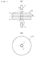
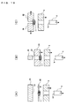
- Figure 1(A) is a cross-sectional side view of essential parts of a tablet compression apparatus that includes a tablet compression die according to the present invention
- Figure 1(B) is a plan view of the die used in the tablet compression apparatus
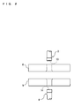
- Figure 2 is an exploded side view of the tablet compression apparatus.
- the tablet compression apparatus comprises a die (tablet compression die or die for the tablet compression apparatus) 2 having the shape of a thick horizontally-oriented plate through which a vertical cylindrical die cavity 1 is formed, and a pair of upper and lower rods 3 and 4 having a cylindrical shape so that the rods can be inserted (fitted) into the die cavity 1 and arranged coaxially with the die cavity 1.
- the inside of the die cavity 1 provides a space S into which the upper and lower rods 3 and 4 are inserted from above and below, respectively.
- the die 2 described above comprises a disk-shaped die main body 7, through which the die cavity 1 described above is formed.
- the die main body 7 is divided into upper and lower parts at a horizontal division plane (division plane) M 1 , which is a horizontal plane that extends perpendicularly to the axis of the rods 3 and 4 and vertically divides the molding groove 6 into equal upper and lower parts.
- the die main body 7 is formed by bringing an upper die 8, which is the upper part, and a lower die 9, which is the lower part, into intimate contact with each other.
- a tablet 11 (see Figure 6 ) held in the molding groove 6 can be removed from the space S with means described later by separating the upper die 8 and the lower die 9 to open the space S.
- a separation mechanism that separates at least a part of the die main body 7 (the upper die 8 or the lower die 9 in the illustrated example) to allow easy removal of the tablet 11 held in the molding groove 6.
- the upper and lower rods 3 and 4 have a larger outer diameter at the tip end part (the lower end part of the upper rod 3 and the upper end part of the lower rod 4), from which the rods are inserted into the die cavity 1, than at the root part and the middle part thereof, and the outer diameter of the upper and lower rods 3 and 4 is substantially equal to the inner diameter of the space S.
- the upper and lower rods 3 and 4 are inserted into the space S from above and below, respectively, so that the rods are slidable in the axial direction.
- the tip end surface of each rod 3, 4 serves as a pressing surface 13, 14 for compressing powder (tabletting powder) 12 charged into the space (see Figure 6 ).
- the pressing surfaces 13 and 14 are concave toward the axis of the rods 3 and 4.
- the upper and lower rods 3 and 4 and the upper and lower dies 8 and 9 are separately vertically moved (lifted and lowered) by one or more actuators (driving means), not shown.
- Figure 3 is a cross-sectional side view of essential parts of the tablet compression apparatus during tablet compression.
- the tablet compression apparatus slides the rods 3 and 4 to positions where the tip ends of the upper and lower rods 3 and 4 come closest to the molding groove 6 (compression molding positions, compression molding completion positions) so that the upper and lower pressing surfaces 13 and 14 and the molding groove 6 are seamlessly connected to each other to form a single, continuous, elliptically curved surface in cross-sectional side view, thereby compressing the powder 12 in the space S into the solid tablet 11 that has a circular shape in plan view and an elliptical shape in side view.
- the pressing surfaces 13 and 14 and the molding groove 6 forms the surface of the tablet 11 by compression.
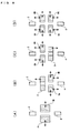
- Figures 4(A) and 4(B) are plan views of tablets having different shapes.
- Figures 4(C) and 4(D) are cross-sectional side view of essential parts of tablet compression apparatuses that differ from the above-described tablet compression apparatus in shape of the molding groove and the pressing surface.
- the tablet 11 has been described as having a circular shape in plan view in the above example, the space S and the molding groove 6 may have an elliptical shape in plan view to mold a tablet 11 by compression into an elliptical shape in plan view (see Figure 4(A) ).
- the space S and the molding groove 6 may have an elongated circular shape (rounded rectangular shape) in plan view to mold a tablet 11 by compression into an elongated circular shape in plan view (see Figure 4(B) ).
- the curvatures of the molding groove 6 and the pressing surfaces 13 and 14 may be modified so that the molding groove 6 and the pair of pressing surfaces 13 and 14 seamlessly connected each other at the time of completion of tablet compression 11 (at the time of molding of the tablet 11) form a circular shape in side view rather than the elliptical shape described above (see Figure 4(C) ).
- the curvature of the molding groove 6 may be modified and the pressing surfaces 13 and 14 may be flattened so that the molding groove 6 and the pair of pressing surfaces 13 and 14 seamlessly connected each other at the time of completion of tablet compression 11 form an elongated circular shape (rounded rectangular shape) in side view (see Figure 4(D) ).
- the molding groove 6 and the pair of pressing surfaces 13 and 14 seamlessly connected to each other at the time of completion of tablet compression molding of the tablet 11 form an elliptical shape having a longitudinal axis oriented perpendicularly to the axial direction of the space S in side view.
- the curvatures of the molding groove 6 and the pressing surfaces 13 and 14 may be modified so that the molding groove 6 and the pressing surfaces 13 and 14 form an elliptical shape having a longitudinal axis oriented in the same direction as the axial direction of the space S in side view.
- Figures 5(A) and 5(B) are a plan view and a side view of a tablet having a different shape.
- the shape of the space S and the molding groove 6 in plan view is modified so that the tablet 11 molded by compression has a rounded triangular shape (a rounded triangular rice-ball shape) in plan view (see Figure 5(A) ), and the curvatures of the molding groove 6 and the pressing surfaces 13 and 14 are modified so that the molding groove 6 and the pair of pressing surfaces 13 and 14 seamlessly connected to each other at the time of completion of tablet compression 11 form an elliptical shape having a longitudinal axis oriented in the same direction as or perpendicularly to the axial direction of the space S in side view (see Figure 5(B) , which shows an example in which the longitudinal axis is oriented perpendicularly to the axial direction of the space S).
- the tablet 11 can have various other rounded polygonal shapes or curved shapes.
- Figures 6(A) to 6(M) are state transition diagrams illustrating a process of molding a solid tablet by compression and removing the tablet by lifting or lowering the upper and lower rods and the lower die with the upper die fixed.
- the lower die 9 is moved upward (lifted or lifted up) to bring the lower die 9 into contact with the upper die 8 to form the die 2
- the upper rod 3 is moved upward from the space S to open the upper end of the space S
- the lower rod 4 is moved upward and inserted into the space S from below to close the lower end of the space S (see Figure 6(A) ).
- the powder 12 is charged into the space S from above until the space S overflows with the powder 12 (see Figure 6(B) ). Then, the lower rod 4 is moved upward or downward (upward in the shown example) to adjust the amount of the powder 12 in the space S (see Figure 6(C) ). Then, a level-off step is performed to scrape off (sweep out) the heap of powder 12 over the space S with a scraper (scraping tool or sweeping tool) 16 or the like that moves leftward and rightward (see Figure 6(D) ).
- the upper rod 3 is inserted into the space S from above and moved downward (lowered or lowered down) to close the upper end of the space S (see Figure 6(E) ). Then, the upper rod 3 is moved downward, and the lower rod 4 is moved upward to the compression molding position to press the powder 12 (see Figure 6(F) ). Then, the upper rod 3 is moved downward to the compression molding position to compress the powder 12 into the solid tablet 11 (see Figure 6(G) ). At this time, the perimeter of the tablet 11 is engaged with and held by the annular molding groove 6.
- the upper and lower rods 3 and 4 and the lower die 9 are moved together downward to separate the tablet 11 from the upper die 8 (see Figure 6(H) ). Then, the lower rod 4 and the lower die 9 are moved together downward to separate the tablet 11 from the upper rod 3 (see Figure 6(I) ). Then, the lower die 9 is moved downward to separate the lower die 9 from the tablet 11, and the upper rod 3 is moved upward (see Figure 6(J) ).
- Figures 7(A) to 7(M) are state transition diagrams illustrating a process of molding a solid tablet by compression and removing the tablet by lifting or lowering the upper and lower rods and the upper die with the lower die fixed.
- the upper rod 3 is moved upward, and the lower rod 4 and the upper die 8 are moved downward to bring the upper die 8 into contact with the lower die 9 to form the die 2, and the upper rod 3 is displaced upward from the space S to open the upper end of the space S, and the lower rod 4 is inserted in the space S from below to close the lower end of the space S (see Figure 7(A) ).
- the powder 12 is charged into the space S from above until the space S overflows with the powder 12 (see Figure 7(B) ). Then, the lower rod 4 is moved upward or downward (upward in the shown example) to adjust the amount of the powder 12 in the space S (see Figure 7(C) ). Then, the level-off step is performed (see Figure 7(D) ).
- the upper rod 3 is inserted into the space S from above and moved downward (lowered or lowered down) to close the upper end of the space S (see Figure 7(E) ). Then, the upper rod 3 is moved downward, and the lower rod 4 is moved upward to the compression molding position to press the powder 12 (see Figure 7(F) ). Then, the upper rod 3 is moved downward to the compression molding position to compress the powder 12 into the solid tablet 11 (see Figure 7(G) ). At this time, the perimeter of the tablet 11 is engaged with and held by the annular molding groove 6.
- the upper die 8 is moved upward to separate the upper die 8 from the tablet 11 (see Figure 7(H) ). Then, the upper rod 3 and the upper die 8 are moved together upward to separate the upper rod 3 from the tablet 11 (see Figure 7(I) ). Then, the lower rod 4 is moved upward to separate the tablet 11 from the lower die 9 (see Figure 7(J) ).
- Figures 8(A) to 8(D) are state transition diagrams illustrating a process of molding a tablet by compression by charging powder into the space with the upper and lower ends of the space closed with the pair of upper and lower rods, respectively.
- the lower rod 4 and the lower die 9 is moved upward to bring the lower die 9 into contact with the upper die 8 to form the die 2 and to close the upper and lower ends of the space S with the upper and lower rods 3 and 4 (see Figure 8(A) ).
- the die 2 is horizontally rotated about a support shaft outside the die 2 (not shown) to produce a centrifugal force, by the action of which the powder 12 is charged into the space S from outside the die 2 through a horizontal supply hole (supply part) 18 that connects the outside of the die 2 and the inside of the space S to each other.
- the lower rod 4 is moved upward or downward to adjust the volume (the amount of the powder 12) in the space S (see Figure 8(B) ).
- the upper rod 3 is moved downward, and the lower rod 4 is moved upward to the compression molding position to press the powder 12 (see Figure 8(C) ).
- the upper rod 3 is moved downward to the compression molding position to compress the powder 12 into the solid tablet 11 (see Figure 8(D) ).
- the perimeter of the tablet 11 is engaged with and held by the annular molding groove 6.
- Figures 9(A) to 9(D) are cross-sectional side views of essential parts of tablet compression apparatuses according to other embodiments of the present invention.
- a separation mechanism that separates the die main body 7 constituting the die 2 at a vertical division plane (division plane) M 2 (see Figure 1(A) ) that extends in the axial direction of the rods 3 and 4 and equally divides the molding groove 6.
- the vertical division plane M 2 extends in the axial direction (vertical direction) and the back-and-forth direction of the rods 3 and 4, and a pair of die divisions 7A and 7B resulting from the division at the vertical division plane M 2 are moved in directions away from and closer to each other (leftward and rightward in the example shown in Figure 9(A) ).
- Figure 9(B) shows an example of the separation mechanism that vertically separates the die main body 7 into the upper die 8 and the lower die 9 at the horizontal division plane M 1 and separates the lower die 9 into a pair of lower die divisions 9A and 9B at the vertical division plane M 2 .
- the pair of lower die divisions 9A and 9B are moved not only in the directions away from and closer to each other but also vertically.
- Figure 9(C) shows an example of the separation mechanism that vertically separates the die main body 7 into the upper die 8 and the lower die 9 at the horizontal division plane M 1 and separates the upper die 8 into a pair of upper die divisions 8A and 8B at the vertical division plane M 2 .
- the pair of upper die divisions 8A and 8B are moved not only in the directions away from and closer to each other but also vertically.
- Figure 9(D) shows an example of the separation mechanism that vertically separates the die main body 7 into the upper die 8 and the lower die 9 at the horizontal division plane M 1 and separates the upper die 8 and the lower die 9 into a pair of upper die divisions 8A and 8B and a pair of lower die divisions 9A and 9B, respectively, at the vertical division plane M 2 .
- the pair of upper die divisions 8A and 8B and the pair of lower die divisions 9A and 9B are moved not only in the directions away from and closer to each other but also vertically.
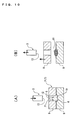
- Figures 10(A) and 10(B) are a cross-sectional side view and an exploded cross-sectional side view of essential parts of a tablet compression apparatus according to another embodiment of the present invention, respectively.
- a vertical cylindrical die hole 21 is formed in an upper part of the die 2.
- the vertical cylindrical die hole 21 is open at the upper end and is defined at the lower end by a curved bottom surface (closed surface) 19 that is concave toward the center thereof.
- the inside of the die hole 21 provides the space S described above.
- a circular ring-shaped molding groove 6 that is seamlessly connected to the bottom surface 19 is formed in the inner circumference of the space S along the entire perimeter thereof at which the inner circumference of the space S connects to the bottom surface 19.
- the molding groove 6, the pressing surface 13 at the tip end of the upper rod 3 and the bottom surface 19 are seamlessly connected to each other to form an elliptical shape in cross-sectional side view, and compress the powder 12 in the space S into the solid tablet 11 having an elliptical shape in side view and a circular shape in plan view. That is, the molding groove 6, the pressing surface 13 of the upper rod 3 and the bottom surface 19 cooperate to form the surface of the tablet 11 by compression.
- the die main body 7 constituting the die 2 has the separation mechanism that vertically separates the die main body 7 into upper and lower parts at the horizontal division plane M 1 , the upper part constitutes the upper die 8, and the lower part constitutes the lower die 9.
- the shape of the tablet 11 can be modified as shown in Figures 4 and 5 by appropriately modifying the shapes of the molding groove 6, the bottom surface 19 and the pressing surface 13 of the upper rod 3 as described above.
- Figures 11(A) to 11(C) are exploded cross-sectional side views of modifications of the tablet compression apparatus shown in Figure 10 .
- Figure 11(A) shows an example in which the lower die 9 is vertically divided into a molding groove-side lower die piece 9C that includes a part of the molding groove 6 and a bottom surface-side lower die piece 9D that includes the bottom surface 19.
- the molding groove-side lower die piece 9C is moved upward to separate the molding groove-side lower die piece 9C from the bottom surface-side lower die piece 9D, thereby separating the tablet 11 from the bottom surface 19 and facilitating removal of the tablet 11.
- Figure 11(B) shows an example in which a cylindrical piece 9E is hollowed out of the lower die 9 from below in such a manner that the cylindrical piece 9E includes the bottom surface 19, and the cylindrical piece 9E is separated from a main body 22 of the lower die 9 to separate the tablet 11 from the bottom surface 19.
- the main body 22 of the lower die 9 is moved upward or downward to separate or couple the main body 22 from or to the cylindrical piece 9E.
- Figure 11(C) shows an example in which the lower die 9 is divided into the pair of lower die divisions 9A and 9B at the vertical division plane M 2 .
- the pair of lower die divisions 9A and 9B are moved in the directions away from and closer to each other, and thus, the tablet 11 on the bottom surface 19 can be easily separated from the bottom surface 19.
- Figures 12(A) and 12(B) are a cross-sectional side view and an exploded cross-sectional front view of essential parts of a tablet compression apparatus according to another embodiment of the present invention, respectively.
- a vertical cylindrical die hole 21 is formed in a lower part of the die 2.
- the vertical cylindrical die hole 21 is open at the lower end and is defined at the upper end by a curved top surface (closed surface) 23 that is concave toward the center thereof.
- the inside of the die hole 21 provides the space S described above.
- a circular ring-shaped molding groove 6 that is seamlessly connected to the top surface 23 is formed in the inner circumference of the space S along the entire perimeter thereof at which the inner circumference of the space S connects to the top surface 23.
- the lower rod 4, which extends in the axial direction of the die hole 21 and is arranged coaxially with the die hole 21, is inserted into the space S through the open end when the space S is charged with a required amount of powder 12.
- the molding groove 6, the pressing surface 14 at the tip end of the lower rod 4 and the top surface 23 are seamlessly connected to each other to form an elliptical shape in cross-sectional side view, and compress the powder 12 in the space S into the solid tablet 11 having an elliptical shape in side view and a circular shape in plan view. That is, the molding groove 6, the pressing surface 14 of the lower rod 4 and the top surface 23 cooperate to form the surface of the tablet 11 by compression.
- the die main body 7 constituting the die 2 has the separation mechanism that vertically separates the die main body 7 into upper and lower parts at the horizontal division plane M 1 , the upper part constitutes the upper die 8, and the lower part constitutes the lower die 9.
- the shape of the tablet 11 can be modified as shown in Figures 4 and 5 by appropriately modifying the shapes of the molding groove 6, the top surface 23 and the pressing surface 14 of the lower rod 4 as described above.
- Figures 13(A) to 13(C) are exploded cross-sectional side views of modifications of the tablet compression apparatus shown in Figure 12 .
- Figure 13(A) shows an example in which the upper die 8 is vertically divided into a molding groove-side upper die piece 8C that includes a part of the molding groove 6 and a top surface-side upper die piece 8D that includes the top surface 23.
- the molding groove-side upper die piece 8C is moved downward to separate the molding groove-side upper die piece 8C from the top surface-side upper die piece 8D, thereby separating the tablet 11 from the top surface 23 and facilitating removal of the tablet 11.
- Figure 13(B) shows an example in which a cylindrical piece 8E is hollowed out of the upper die 8 from above in such a manner that the cylindrical piece 8E includes the top surface 23, and the cylindrical piece 8E is separated from a main body 24 of the upper die 8 to separate the tablet 11 from the bottom surface 19.
- the main body 24 of the upper die 8 is moved upward or downward to couple or separate the cylindrical piece 8E and the main body 24 to or from each other.
- Figure 13(C) shows an example in which the upper die 8 is divided into the pair of upper die divisions 8A and 8B at the vertical division plane M 2 .
- the pair of upper die divisions 8A and 8B are moved in the directions away from and closer to each other, and thus, the tablet 11 on the top surface 23 can be easily separated from the top surface 23.
Landscapes
- Engineering & Computer Science (AREA)
- Mechanical Engineering (AREA)
- Medical Preparation Storing Or Oral Administration Devices (AREA)
- Processing And Handling Of Plastics And Other Materials For Molding In General (AREA)
- Medicinal Preparation (AREA)
- Agricultural Chemicals And Associated Chemicals (AREA)
Abstract
Description
- The present invention relates to a tablet compression die used for compressing powder into a solid tablet.
- A known tablet compression apparatus (tablet compression machine) used for producing a tablet comprises a pair of upper and lower rods having a pressing surface at the tip end and a die (tablet compression die or die for the tablet compression apparatus) having a die cavity (space) that extends in the vertical direction (the direction of the axis of the rods) and is open at the vertical opposite ends so that the rods can be inserted into the die cavity. Powder (tabletting powder) is charged into the die cavity, the tip ends of the pair of upper and lower rods are inserted into the die cavity through the upper and lower open ends thereof, and then, the powder in the space is compressed between the pair of pressing surfaces into a solid tablet (see Japanese Patent Laid-Open Nos.
4-28498 7-8540 2002-1593 2002-103096 7-124231 - The tablet compression apparatus configured as described above applies a high force to each rod to achieve tablet compression (tableting). Thus, if the upper and lower rods come into contact with each other at the tip ends during tablet compresstion, the tip ends of the rods may be damaged or deformed. To avoid such a trouble, the upper and lower rods are configured not to come into contact with each other during tablet compression. In addition, the pressing surfaces at the tip ends of the rods, which are horizontally oriented, and the inner surface of the die cavity, which is vertically oriented, are not seamlessly connected to each other. As a result, an edge (protrusion or recess) is formed on the surface of the tablet by compression along the boundaries between the pressing surfaces of the rods and the inner surface of the die cavity.
- The edge on the surface of the tablet is relatively fragile to chipping and may become chipped during film coating to lead a defective tablet. Although the tablet surface can be sugar-coated to cover the edge thereon, the sugar-coated tablet is significantly larger than the tablet without the sugar coating. Thus, this technique is difficult to use for a tablet that has a size restriction.
- To overcome these disadvantages, a tablet chamfering technique has been developed and known that produces a tablet without an edge by trimming the edge on the surface of the tablet by compression (see
Patent Literatures 1 to 3). -
- Patent Literature 1: Japanese Patent Laid-Open No.
48-99079 - Patent Literature 2: Japanese Patent Laid-Open No.
53-19977 - Patent Literature 3: Japanese Patent Publication No.
53-47357 - The techniques disclosed in Patent Literatures described above have problems that the tablet may have a coarse surface because of the trimming and the part trimmed off may have medicinal properties. Thus, there is a demand for a technique that prevents formation of an edge during tablet compression.
An object of the present invention is to solve the problems described above and provide a tablet compression die that prevents formation of an edge on the surface of a solid tablet during tablet compression. - In order to solve the problems described above, in the first place, a tablet compression apparatus according to the present invention is a tablet compression die having a space S extending in an axial direction of
rods rods surfaces pressing surfaces powder 12 in the space S into asolid tablet 11 by compression, characterized in that an annularconcave molding groove 6, which is seamlessly connected to thepressing surfaces tablet 11 during tablet compression, is formed in an inner circumference of the space S, and the tablet compression die has a separation mechanism that separates at least a part of a diemain body 7 to allow removal of thetablet 11 held in theannular molding groove 6. - In the second place, the tablet compression apparatus is characterized in that the tablet compression die has a
die cavity 1 whose inside provides the space S and that is open at opposite ends and extends in the axial direction of therods rods pressing surfaces rods molding groove 6 are seamlessly connected to each other to form a single circular, elliptical or elongated circular shape in cross-sectional side view during tablet compression. - In the third place, the tablet compression apparatus is characterized in that the tablet compression die has a
die hole 21 whose inside provides the space S and that is open at one end to allow insertion of therod surface rods surface pressing surface molding groove 6 are seamlessly connected to each other to form a single circular, elliptical or elongated circular shape in cross-sectional side view during tablet compression. - In the fourth place, the tablet compression apparatus is characterized in that the separation mechanism separates the die
main body 7 at a plane that extends in the axial directions of therods molding groove 6. - In the fifth place, the tablet compression apparatus is characterized in that the separation mechanism separates the die
main body 7 at a plane that extends in a direction perpendicular to the axial directions of therods molding groove 6. - The tablet compression die according to the present invention configured as described above has an advantage that formation of an edge on the surface of the tablet is prevented during tablet compression because the annular concave molding groove that is seamlessly connected to the pressing surfaces to form a part of the surface of the tablet during tableting is formed in the inner circumference of the space. In addition, the tablet compression die has an advantage that the tablet can be easily removed because of the separation mechanism that separates at least a part of the die main body so that the tablet held in the annular molding groove can be removed.
-
- [
Figure 1] Figure 1(A) is a cross-sectional side view of essential parts of a tablet compression apparatus that includes a tablet compression die according to the present invention, andFigure 1(B) is a plan view of the die used in the tablet compression apparatus. - [
Figure 2] Figure 2 is an exploded side view of the tablet compression apparatus. - [
Figure 3] Figure 3 is a cross-sectional side view of essential parts of the tablet compression apparatus during compression molding of a tablet. - [
Figure 4] Figures 4(A) and 4(B) are plan views of tablets having different shapes, andFigures 4(C) and 4(D) are cross-sectional side views of essential parts of tablet compression apparatuses that differ in shape of the molding groove and the pressing surface. - [
Figure 5] Figures 5(A) and 5(B) are a plan view and a side view of a tablet having a different shape, respectively. - [
Figure 6] Figures 6(A) to 6(M) are state transition diagrams illustrating a process of molding a solid tablet by compression and removing the tablet by lifting or lowering an upper and an lower rod and a lower die with an upper die fixed. - [
Figure 7] Figures 7(A) to 7(M) are state transition diagrams illustrating a process of molding a solid tablet by compression and removing the tablet by lifting or lowering the upper and lower rods and the upper die with the lower die fixed. - [
Figure 8] Figures 8(A) to 8(D) are state transition diagrams illustrating a process of molding a tablet by compression by charging powder into a space with the upper and lower ends of the space closed with the pair of upper and lower rods, respectively. - [
Figure 9] Figures 9(A) to 9(D) are cross-sectional side views of essential parts of tablet compression apparatuses according to other embodiments of the present invention. - [
Figure 10] Figures 10(A) and 10(B) are a cross-sectional side vide and an exploded cross-sectional front view of essential parts of a tablet compression apparatus according to another embodiment of the present invention, respectively. - [
Figure 11] Figures 11(A) to 11(C) are exploded cross-sectional side views of modifications of the tablet compression apparatus shown inFigure 10 . - [
Figure 12] Figures 12(A) and 12(B) are a cross-sectional side vide and an exploded cross-sectional front view of essential parts of a tablet compression apparatus according to another embodiment of the present invention, respectively. - [
Figure 13] Figures 13(A) to 13(C) are exploded cross-sectional side views of modifications of the tablet compression apparatus shown inFigure 12 . -
- 1
- die cavity
- 3
- upper rod (rod)
- 4
- lower rod (rod)
- 6
- molding groove (rounded annular surface)
- 7
- die main body
- 11
- tablet
- 12
- powder (tabletting powder)
- 13
- pressing surface
- 14
- pressing surface
- 19
- bottom surface (closed surface)
- 21
- die hole
- 23
- top surface (closed surface)
- S
- space
- In the following, embodiments of the present invention will be described with regard to examples shown in the drawings.
Figure 1(A) is a cross-sectional side view of essential parts of a tablet compression apparatus that includes a tablet compression die according to the present invention,Figure 1(B) is a plan view of the die used in the tablet compression apparatus, andFigure 2 is an exploded side view of the tablet compression apparatus. The tablet compression apparatus comprises a die (tablet compression die or die for the tablet compression apparatus) 2 having the shape of a thick horizontally-oriented plate through which a verticalcylindrical die cavity 1 is formed, and a pair of upper andlower rods die cavity 1 and arranged coaxially with thedie cavity 1. - The inside of the
die cavity 1 provides a space S into which the upper andlower rods - The
die 2 described above comprises a disk-shaped diemain body 7, through which thedie cavity 1 described above is formed. The diemain body 7 is divided into upper and lower parts at a horizontal division plane (division plane) M1, which is a horizontal plane that extends perpendicularly to the axis of therods molding groove 6 into equal upper and lower parts. The diemain body 7 is formed by bringing anupper die 8, which is the upper part, and alower die 9, which is the lower part, into intimate contact with each other. A tablet 11 (seeFigure 6 ) held in themolding groove 6 can be removed from the space S with means described later by separating theupper die 8 and thelower die 9 to open the space S. - That is, there is provided a separation mechanism that separates at least a part of the die main body 7 (the
upper die 8 or thelower die 9 in the illustrated example) to allow easy removal of thetablet 11 held in themolding groove 6. - The upper and
lower rods upper rod 3 and the upper end part of the lower rod 4), from which the rods are inserted into thedie cavity 1, than at the root part and the middle part thereof, and the outer diameter of the upper andlower rods lower rods rod pressing surface Figure 6 ). The pressing surfaces 13 and 14 are concave toward the axis of therods - The upper and
lower rods -
Figure 3 is a cross-sectional side view of essential parts of the tablet compression apparatus during tablet compression. Once the upper andlower rods rods lower rods pressing surfaces molding groove 6 are seamlessly connected to each other to form a single, continuous, elliptically curved surface in cross-sectional side view, thereby compressing thepowder 12 in the space S into thesolid tablet 11 that has a circular shape in plan view and an elliptical shape in side view. In short, thepressing surfaces molding groove 6 forms the surface of thetablet 11 by compression. -
Figures 4(A) and 4(B) are plan views of tablets having different shapes.Figures 4(C) and 4(D) are cross-sectional side view of essential parts of tablet compression apparatuses that differ from the above-described tablet compression apparatus in shape of the molding groove and the pressing surface. Although thetablet 11 has been described as having a circular shape in plan view in the above example, the space S and themolding groove 6 may have an elliptical shape in plan view to mold atablet 11 by compression into an elliptical shape in plan view (seeFigure 4(A) ). Alternatively, the space S and themolding groove 6 may have an elongated circular shape (rounded rectangular shape) in plan view to mold atablet 11 by compression into an elongated circular shape in plan view (seeFigure 4(B) ). - Alternatively, the curvatures of the
molding groove 6 and thepressing surfaces molding groove 6 and the pair ofpressing surfaces Figure 4(C) ). Alternatively, the curvature of themolding groove 6 may be modified and thepressing surfaces molding groove 6 and the pair ofpressing surfaces tablet compression 11 form an elongated circular shape (rounded rectangular shape) in side view (seeFigure 4(D) ). - In the example shown in
Figure 3 , themolding groove 6 and the pair ofpressing surfaces tablet 11 form an elliptical shape having a longitudinal axis oriented perpendicularly to the axial direction of the space S in side view. However, the curvatures of themolding groove 6 and thepressing surfaces molding groove 6 and thepressing surfaces -
Figures 5(A) and 5(B) are a plan view and a side view of a tablet having a different shape. In the example shown in these drawings, the shape of the space S and themolding groove 6 in plan view is modified so that thetablet 11 molded by compression has a rounded triangular shape (a rounded triangular rice-ball shape) in plan view (seeFigure 5(A) ), and the curvatures of themolding groove 6 and thepressing surfaces molding groove 6 and the pair ofpressing surfaces tablet compression 11 form an elliptical shape having a longitudinal axis oriented in the same direction as or perpendicularly to the axial direction of the space S in side view (seeFigure 5(B) , which shows an example in which the longitudinal axis is oriented perpendicularly to the axial direction of the space S). Thetablet 11 can have various other rounded polygonal shapes or curved shapes. -
Figures 6(A) to 6(M) are state transition diagrams illustrating a process of molding a solid tablet by compression and removing the tablet by lifting or lowering the upper and lower rods and the lower die with the upper die fixed. First, thelower die 9 is moved upward (lifted or lifted up) to bring thelower die 9 into contact with theupper die 8 to form thedie 2, theupper rod 3 is moved upward from the space S to open the upper end of the space S, and thelower rod 4 is moved upward and inserted into the space S from below to close the lower end of the space S (seeFigure 6(A) ). - Then, the
powder 12 is charged into the space S from above until the space S overflows with the powder 12 (seeFigure 6(B) ). Then, thelower rod 4 is moved upward or downward (upward in the shown example) to adjust the amount of thepowder 12 in the space S (seeFigure 6(C) ). Then, a level-off step is performed to scrape off (sweep out) the heap ofpowder 12 over the space S with a scraper (scraping tool or sweeping tool) 16 or the like that moves leftward and rightward (seeFigure 6(D) ). - Then, the
upper rod 3 is inserted into the space S from above and moved downward (lowered or lowered down) to close the upper end of the space S (seeFigure 6(E) ). Then, theupper rod 3 is moved downward, and thelower rod 4 is moved upward to the compression molding position to press the powder 12 (seeFigure 6(F) ). Then, theupper rod 3 is moved downward to the compression molding position to compress thepowder 12 into the solid tablet 11 (seeFigure 6(G) ). At this time, the perimeter of thetablet 11 is engaged with and held by theannular molding groove 6. - To disengage and remove the
tablet 11 from thedie 2, first, the upper andlower rods lower die 9 are moved together downward to separate thetablet 11 from the upper die 8 (seeFigure 6(H) ). Then, thelower rod 4 and thelower die 9 are moved together downward to separate thetablet 11 from the upper rod 3 (seeFigure 6(I) ). Then, thelower die 9 is moved downward to separate thelower die 9 from thetablet 11, and theupper rod 3 is moved upward (seeFigure 6(J) ). - Then, using a removal plate (removal tool) 17 or the like that moves leftward and rightward, the
tablet 11 placed on thelower rod 4 is discharged and removed from the tablet compression apparatus (seeFigure 6(K) ). Then, theupper rod 3 is moved upward and separated from the upper die 8 (seeFigure 6(L) ), and then, the upper andlower rods lower die 9 are moved upward (seeFigure 6(M) ) to restore the tablet compression apparatus to the state shown inFigure 6(A) . Then, the process shown inFigures 6(A) to 6(M) is repeated to successively mold thesolid tablets 11 by compression and remove thesolid tablets 11. -
Figures 7(A) to 7(M) are state transition diagrams illustrating a process of molding a solid tablet by compression and removing the tablet by lifting or lowering the upper and lower rods and the upper die with the lower die fixed. First, theupper rod 3 is moved upward, and thelower rod 4 and theupper die 8 are moved downward to bring theupper die 8 into contact with thelower die 9 to form thedie 2, and theupper rod 3 is displaced upward from the space S to open the upper end of the space S, and thelower rod 4 is inserted in the space S from below to close the lower end of the space S (seeFigure 7(A) ). - Then, the
powder 12 is charged into the space S from above until the space S overflows with the powder 12 (seeFigure 7(B) ). Then, thelower rod 4 is moved upward or downward (upward in the shown example) to adjust the amount of thepowder 12 in the space S (seeFigure 7(C) ). Then, the level-off step is performed (seeFigure 7(D) ). - Then, the
upper rod 3 is inserted into the space S from above and moved downward (lowered or lowered down) to close the upper end of the space S (seeFigure 7(E) ). Then, theupper rod 3 is moved downward, and thelower rod 4 is moved upward to the compression molding position to press the powder 12 (seeFigure 7(F) ). Then, theupper rod 3 is moved downward to the compression molding position to compress thepowder 12 into the solid tablet 11 (seeFigure 7(G) ). At this time, the perimeter of thetablet 11 is engaged with and held by theannular molding groove 6. - To disengage and remove the
tablet 11 from thedie 2, first, theupper die 8 is moved upward to separate theupper die 8 from the tablet 11 (seeFigure 7(H) ). Then, theupper rod 3 and theupper die 8 are moved together upward to separate theupper rod 3 from the tablet 11 (seeFigure 7(I) ). Then, thelower rod 4 is moved upward to separate thetablet 11 from the lower die 9 (seeFigure 7(J) ). - Then, using the
removal plate 17 or the like that moves leftward and rightward, thetablet 11 placed on thelower rod 4 is discharged and removed from the tablet compression apparatus (seeFigures 7(K) and (L) ). Then, theupper rod 3 is moved upward, and thelower rod 4 and theupper die 8 are moved downward to restore the tablet compression apparatus to the state shown inFigure 7(A) . Then, the process shown inFigures 7(A) to 7(M) is repeated to successively mold thesolid tablets 11 by compression and remove thesolid tablets 11. -
Figures 8(A) to 8(D) are state transition diagrams illustrating a process of molding a tablet by compression by charging powder into the space with the upper and lower ends of the space closed with the pair of upper and lower rods, respectively. First, thelower rod 4 and thelower die 9 is moved upward to bring thelower die 9 into contact with theupper die 8 to form thedie 2 and to close the upper and lower ends of the space S with the upper andlower rods 3 and 4 (seeFigure 8(A) ). - Then, the
die 2 is horizontally rotated about a support shaft outside the die 2 (not shown) to produce a centrifugal force, by the action of which thepowder 12 is charged into the space S from outside thedie 2 through a horizontal supply hole (supply part) 18 that connects the outside of thedie 2 and the inside of the space S to each other. As required, thelower rod 4 is moved upward or downward to adjust the volume (the amount of the powder 12) in the space S (seeFigure 8(B) ). Then, theupper rod 3 is moved downward, and thelower rod 4 is moved upward to the compression molding position to press the powder 12 (seeFigure 8(C) ). Then, theupper rod 3 is moved downward to the compression molding position to compress thepowder 12 into the solid tablet 11 (seeFigure 8(D) ). At this time, the perimeter of thetablet 11 is engaged with and held by theannular molding groove 6. - Then, the upper and
lower rods lower die 9 are moved upward or downward as shown inFigures 6(H) to 6(K) so that thetablet 11 can be removed, theupper die 8 and thelower die 9 are separated from each other with theupper rod 3 inserted in theupper die 8. Then, thelower rod 4 and thelower die 9 are moved upward to restore the tablet compression apparatus to the state shown inFigure 8(A) . - Next, other embodiments of the present invention will be described with regard to differences from the embodiment described above.
Figures 9(A) to 9(D) are cross-sectional side views of essential parts of tablet compression apparatuses according to other embodiments of the present invention. As shown inFigure 9(A) , there is provided a separation mechanism that separates the diemain body 7 constituting thedie 2 at a vertical division plane (division plane) M2 (seeFigure 1(A) ) that extends in the axial direction of therods molding groove 6. - In the example shown in
Figure 1(A) , the vertical division plane M2 extends in the axial direction (vertical direction) and the back-and-forth direction of therods die divisions Figure 9(A) ). -
Figure 9(B) shows an example of the separation mechanism that vertically separates the diemain body 7 into theupper die 8 and thelower die 9 at the horizontal division plane M1 and separates thelower die 9 into a pair oflower die divisions lower die divisions -
Figure 9(C) shows an example of the separation mechanism that vertically separates the diemain body 7 into theupper die 8 and thelower die 9 at the horizontal division plane M1 and separates theupper die 8 into a pair ofupper die divisions upper die divisions -
Figure 9(D) shows an example of the separation mechanism that vertically separates the diemain body 7 into theupper die 8 and thelower die 9 at the horizontal division plane M1 and separates theupper die 8 and thelower die 9 into a pair ofupper die divisions lower die divisions upper die divisions lower die divisions - Next, another embodiment of the present invention will be described with regard to differences from the embodiments described above.
Figures 10(A) and 10(B) are a cross-sectional side view and an exploded cross-sectional side view of essential parts of a tablet compression apparatus according to another embodiment of the present invention, respectively. With the tablet compression apparatus, a verticalcylindrical die hole 21 is formed in an upper part of thedie 2. The verticalcylindrical die hole 21 is open at the upper end and is defined at the lower end by a curved bottom surface (closed surface) 19 that is concave toward the center thereof. The inside of thedie hole 21 provides the space S described above. - A circular ring-shaped
molding groove 6 that is seamlessly connected to thebottom surface 19 is formed in the inner circumference of the space S along the entire perimeter thereof at which the inner circumference of the space S connects to thebottom surface 19. Theupper rod 3, which extends in the axial direction of thedie hole 21 and is arranged coaxially with thedie hole 21, is inserted into the space S through the open end. When the tip end of theupper rod 3 is moved downward to the compression molding position in the space S, themolding groove 6, thepressing surface 13 at the tip end of theupper rod 3 and thebottom surface 19 are seamlessly connected to each other to form an elliptical shape in cross-sectional side view, and compress thepowder 12 in the space S into thesolid tablet 11 having an elliptical shape in side view and a circular shape in plan view. That is, themolding groove 6, thepressing surface 13 of theupper rod 3 and thebottom surface 19 cooperate to form the surface of thetablet 11 by compression. - The die
main body 7 constituting thedie 2 has the separation mechanism that vertically separates the diemain body 7 into upper and lower parts at the horizontal division plane M1, the upper part constitutes theupper die 8, and the lower part constitutes thelower die 9. The shape of thetablet 11 can be modified as shown inFigures 4 and5 by appropriately modifying the shapes of themolding groove 6, thebottom surface 19 and thepressing surface 13 of theupper rod 3 as described above. -
Figures 11(A) to 11(C) are exploded cross-sectional side views of modifications of the tablet compression apparatus shown inFigure 10 .Figure 11(A) shows an example in which thelower die 9 is vertically divided into a molding groove-sidelower die piece 9C that includes a part of themolding groove 6 and a bottom surface-sidelower die piece 9D that includes thebottom surface 19. The molding groove-sidelower die piece 9C is moved upward to separate the molding groove-sidelower die piece 9C from the bottom surface-sidelower die piece 9D, thereby separating thetablet 11 from thebottom surface 19 and facilitating removal of thetablet 11. -
Figure 11(B) shows an example in which acylindrical piece 9E is hollowed out of thelower die 9 from below in such a manner that thecylindrical piece 9E includes thebottom surface 19, and thecylindrical piece 9E is separated from amain body 22 of thelower die 9 to separate thetablet 11 from thebottom surface 19. Themain body 22 of thelower die 9 is moved upward or downward to separate or couple themain body 22 from or to thecylindrical piece 9E. -
Figure 11(C) shows an example in which thelower die 9 is divided into the pair oflower die divisions lower die divisions tablet 11 on thebottom surface 19 can be easily separated from thebottom surface 19. - Next, another embodiment of the present invention will be described with regard to differences from the embodiments described above.
Figures 12(A) and 12(B) are a cross-sectional side view and an exploded cross-sectional front view of essential parts of a tablet compression apparatus according to another embodiment of the present invention, respectively. With the tablet compression apparatus, a verticalcylindrical die hole 21 is formed in a lower part of thedie 2. The verticalcylindrical die hole 21 is open at the lower end and is defined at the upper end by a curved top surface (closed surface) 23 that is concave toward the center thereof. The inside of thedie hole 21 provides the space S described above. - A circular ring-shaped
molding groove 6 that is seamlessly connected to thetop surface 23 is formed in the inner circumference of the space S along the entire perimeter thereof at which the inner circumference of the space S connects to thetop surface 23. Thelower rod 4, which extends in the axial direction of thedie hole 21 and is arranged coaxially with thedie hole 21, is inserted into the space S through the open end when the space S is charged with a required amount ofpowder 12. When the tip end of thelower rod 4 is moved upward to the compression molding position in the space S, themolding groove 6, thepressing surface 14 at the tip end of thelower rod 4 and thetop surface 23 are seamlessly connected to each other to form an elliptical shape in cross-sectional side view, and compress thepowder 12 in the space S into thesolid tablet 11 having an elliptical shape in side view and a circular shape in plan view. That is, themolding groove 6, thepressing surface 14 of thelower rod 4 and thetop surface 23 cooperate to form the surface of thetablet 11 by compression. - The die
main body 7 constituting thedie 2 has the separation mechanism that vertically separates the diemain body 7 into upper and lower parts at the horizontal division plane M1, the upper part constitutes theupper die 8, and the lower part constitutes thelower die 9. The shape of thetablet 11 can be modified as shown inFigures 4 and5 by appropriately modifying the shapes of themolding groove 6, thetop surface 23 and thepressing surface 14 of thelower rod 4 as described above. -
Figures 13(A) to 13(C) are exploded cross-sectional side views of modifications of the tablet compression apparatus shown inFigure 12 .Figure 13(A) shows an example in which theupper die 8 is vertically divided into a molding groove-sideupper die piece 8C that includes a part of themolding groove 6 and a top surface-sideupper die piece 8D that includes thetop surface 23. The molding groove-sideupper die piece 8C is moved downward to separate the molding groove-sideupper die piece 8C from the top surface-sideupper die piece 8D, thereby separating thetablet 11 from thetop surface 23 and facilitating removal of thetablet 11. -
Figure 13(B) shows an example in which acylindrical piece 8E is hollowed out of theupper die 8 from above in such a manner that thecylindrical piece 8E includes thetop surface 23, and thecylindrical piece 8E is separated from amain body 24 of theupper die 8 to separate thetablet 11 from thebottom surface 19. Themain body 24 of theupper die 8 is moved upward or downward to couple or separate thecylindrical piece 8E and themain body 24 to or from each other. -
Figure 13(C) shows an example in which theupper die 8 is divided into the pair ofupper die divisions upper die divisions tablet 11 on thetop surface 23 can be easily separated from thetop surface 23.
Claims (5)
- A tablet compression die having a space (S) extending in an axial direction of rods (3) and (4) into which the rods are inserted, the rods (3) and (4) having pressing surfaces (13) and (14) at a tip end, respectively, and said pressing surfaces (13) and (14) the powder (12) in the space (S) into a solid tablet (11) by compression,
wherein an annular concave molding groove (6), which is seamlessly connected to said pressing surfaces (13) and (14) to form a part of the surface of the tablet (11) during tableting, is formed in an inner circumference of the space (S), and
the tablet compression die has a separation mechanism that separates at least a part of a die main body (7) to allow removal of the tablet (11) held in the annular molding groove (6). - The tablet compression die according to Claim 1, wherein the tablet compression die has a die cavity (1) whose inside provides the space (S) and that is open at opposite ends and extends in the axial direction of the rods (3) and (4) to allow insertion of the pair of rods (3) and (4) through the opposite open ends, and the pressing surfaces (13) and (14) of the pair of rods (3) and (4) and said molding groove (6) are seamlessly connected to each other to form a single circular, elliptical or elongated circular shape in cross-sectional side view during tableting.
- The tablet compression die according to Claim 1, wherein the tablet compression die has a die hole (21) whose inside provides the space (S) and that is open at one end to allow insertion of the rod (3) or (4) and defined at the other end by a closed surface (19) or (23) and extends in the axial direction of the rods (3) and (4), and said closed surface (19) or (23), the pressing surface (13) or (14) and the molding groove (6) are seamlessly connected to each other to form a single circular, elliptical or elongated circular shape in cross-sectional side view during tableting.
- The tablet compression die according to Claim 1, 2 or 3, wherein the separation mechanism separates the die main body (7) at a plane that extends in the axial directions of the rods (3) and (4) and divides the molding groove (6).
- The tablet compression die according to Claim 1, 2, 3 or 4, wherein the separation mechanism separates the die main body (7) at a plane that extends in a direction perpendicular to the axial directions of the rods (3) and (4) and divides the molding groove (6).
Applications Claiming Priority (2)
| Application Number | Priority Date | Filing Date | Title |
|---|---|---|---|
| JP2008229574 | 2008-09-08 | ||
| PCT/JP2009/065581 WO2010027069A1 (en) | 2008-09-08 | 2009-09-07 | Tablet compression die |
Publications (2)
| Publication Number | Publication Date |
|---|---|
| EP2335915A1 true EP2335915A1 (en) | 2011-06-22 |
| EP2335915A4 EP2335915A4 (en) | 2012-03-28 |
Family
ID=41797232
Family Applications (1)
| Application Number | Title | Priority Date | Filing Date |
|---|---|---|---|
| EP20090811593 Withdrawn EP2335915A4 (en) | 2008-09-08 | 2009-09-07 | COMPRESSOR MATRIX OF TABLETS |
Country Status (5)
| Country | Link |
|---|---|
| US (1) | US20110159137A1 (en) |
| EP (1) | EP2335915A4 (en) |
| JP (1) | JPWO2010027069A1 (en) |
| CN (1) | CN102149536A (en) |
| WO (1) | WO2010027069A1 (en) |
Cited By (1)
| Publication number | Priority date | Publication date | Assignee | Title |
|---|---|---|---|---|
| EP4253027A1 (en) * | 2022-03-29 | 2023-10-04 | Korsch AG | Device for producing borderless pressed articles |
Families Citing this family (11)
| Publication number | Priority date | Publication date | Assignee | Title |
|---|---|---|---|---|
| JP5693255B2 (en) * | 2011-01-20 | 2015-04-01 | 株式会社菊水製作所 | Powder compression molding machine and method for producing molded product |
| JP5810465B2 (en) * | 2011-11-04 | 2015-11-11 | 住友電工焼結合金株式会社 | Mold for powder molding |
| KR101565456B1 (en) * | 2015-04-06 | 2015-11-05 | (주)아리바이오테크 | Apparatus for producing tablet |
| JP6541608B2 (en) * | 2016-04-15 | 2019-07-10 | Towa株式会社 | Tableting punch or die and tableting apparatus including the same |
| CA3063711A1 (en) | 2017-05-17 | 2018-11-22 | Massachusetts Institute Of Technology | Self-righting systems, methods, and related components |
| CN107931602B (en) * | 2017-10-25 | 2021-03-02 | 株洲钻石切削刀具股份有限公司 | Forming device and forming method of powder metallurgy bar |
| EP3793667A1 (en) | 2018-05-17 | 2021-03-24 | Massachusetts Institute of Technology | Systems for electrical stimulation |
| US11779522B2 (en) * | 2018-12-07 | 2023-10-10 | Incube Labs, Llc | Apparatus for manufacturing microtablets |
| US11541216B2 (en) | 2019-11-21 | 2023-01-03 | Massachusetts Institute Of Technology | Methods for manufacturing tissue interfacing components |
| DE102020127325A1 (en) * | 2020-10-16 | 2022-04-21 | Schaeffler Technologies AG & Co. KG | Press tool, press device, method for pressing and spherical ceramic green body |
| CN120079864B (en) * | 2025-05-08 | 2025-07-22 | 成都大学 | High-precision continuous compression molding device and method for powder metallurgy blank with inner sink groove |
Family Cites Families (18)
| Publication number | Priority date | Publication date | Assignee | Title |
|---|---|---|---|---|
| FR348476A (en) * | 1904-11-02 | 1905-04-14 | Anne Marie Lucien Lacaze | Machine for compressing powdery materials into blocks of various shapes and mainly spherical in shape |
| US3255279A (en) * | 1964-10-13 | 1966-06-07 | Air Reduction | Flashless encapsulated sphere manufacture |
| US4047864A (en) * | 1975-10-06 | 1977-09-13 | Wolverine Aluminum Corporation | Apparatus for producing spherical articles |
| US4230653A (en) * | 1978-08-28 | 1980-10-28 | Ptx-Pentronix, Inc. | Method for producing spherical articles |
| JPS57103800A (en) * | 1980-12-18 | 1982-06-28 | Ngk Spark Plug Co Ltd | Production of powder molding having body part of different diameter |
| JPS63250404A (en) * | 1987-04-07 | 1988-10-18 | Keita Hirai | Press for compacting rotatory body |
| JPH0726074Y2 (en) * | 1989-03-16 | 1995-06-14 | 株式会社菊水製作所 | Double coated tablet manufacturing equipment |
| US5648033A (en) * | 1993-09-10 | 1997-07-15 | Fuisz Technologies Ltd. | Method and apparatus for retaining a formed compression dosage unit within a die cavity |
| EP0680405B1 (en) * | 1993-11-24 | 1999-08-04 | Stackpole Limited | Phased split die |
| US6535637B1 (en) * | 1997-04-04 | 2003-03-18 | Esco Electronics, Inc. | Pharmaceutical pill recognition and verification system |
| US6080358A (en) * | 1997-12-24 | 2000-06-27 | Hitachi Powdered Metals Co., Ltd. | Method for forming compacts |
| DE19901383A1 (en) * | 1999-01-15 | 2000-07-20 | Knoll Ag | Process for the preparation of different solid dosage forms |
| CN1255265C (en) * | 2001-08-30 | 2006-05-10 | 株式会社三和化学研究所 | Device for producing molded articles, and a molded article that can be produced by such device |
| DE20115860U1 (en) * | 2001-09-17 | 2001-12-13 | Schneider, Harald, 34277 Fuldabrück | Pressing device |
| WO2005046978A1 (en) * | 2003-11-14 | 2005-05-26 | Sanwa Kagaku Kenkyusho Co., Ltd. | Method of manufacturing nucleated molding |
| JP4920172B2 (en) * | 2003-12-22 | 2012-04-18 | 三菱マテリアル株式会社 | Method of manufacturing cutting blade member of cutting tool and press molding die of green compact used in the manufacturing method |
| JP4529620B2 (en) * | 2004-09-28 | 2010-08-25 | 三菱マテリアル株式会社 | Method of manufacturing cutting blade member of cutting tool and press molding die of green compact used in the manufacturing method |
| IL166530A (en) * | 2005-01-27 | 2009-06-15 | Iscar Ltd | Method for manufacturing cutting inserts |
-
2009
- 2009-09-07 CN CN2009801348086A patent/CN102149536A/en active Pending
- 2009-09-07 US US13/062,415 patent/US20110159137A1/en not_active Abandoned
- 2009-09-07 JP JP2010527843A patent/JPWO2010027069A1/en active Pending
- 2009-09-07 EP EP20090811593 patent/EP2335915A4/en not_active Withdrawn
- 2009-09-07 WO PCT/JP2009/065581 patent/WO2010027069A1/en not_active Ceased
Cited By (2)
| Publication number | Priority date | Publication date | Assignee | Title |
|---|---|---|---|---|
| EP4253027A1 (en) * | 2022-03-29 | 2023-10-04 | Korsch AG | Device for producing borderless pressed articles |
| EP4253026A1 (en) * | 2022-03-29 | 2023-10-04 | Korsch AG | Device for producing edge-free pressed items |
Also Published As
| Publication number | Publication date |
|---|---|
| JPWO2010027069A1 (en) | 2012-02-02 |
| WO2010027069A1 (en) | 2010-03-11 |
| EP2335915A4 (en) | 2012-03-28 |
| CN102149536A (en) | 2011-08-10 |
| US20110159137A1 (en) | 2011-06-30 |
Similar Documents
| Publication | Publication Date | Title |
|---|---|---|
| US20110159137A1 (en) | Tablet compression die | |
| CN101765471B (en) | Device and method for calibrating a sintered molded part | |
| WO2018221497A1 (en) | Powder molding press method of green compact for cutting insert, and powder molding press device | |
| CN106734819B (en) | A kind of processing mold and its method of multisection type helical tooth | |
| CN101954579A (en) | Plastic cap nut full-automatic capping machine | |
| CN119772175A (en) | Powder metallurgy gear forming processing equipment and method | |
| CN103909562A (en) | Forming machine for ceramic lamp holders | |
| JPH09262697A (en) | Powder compacting device | |
| CN217748917U (en) | Punching and blanking composite die with material receiving device | |
| CN208180121U (en) | A kind of precision die mounting and positioning device | |
| CN218593764U (en) | Pressing die for low-loss magnetic core | |
| CN213291455U (en) | Pharmacy mascerating machine is used in production of avanafil | |
| US20090257904A1 (en) | Device and method for pressing a metal powder compact | |
| JP5412058B2 (en) | Powder molding equipment | |
| EP2605670B1 (en) | Compression unit, press and method of compressing tobacco cut filler | |
| CN209156907U (en) | A kind of breakdown drawing and forming combination die | |
| CN218228044U (en) | Tablet press | |
| CN117301614B (en) | A powder pressing tool and pressing method for anti-adhesion conical surface forming | |
| JP3865544B2 (en) | Compacting method for helical gear | |
| CN110771647A (en) | Moon cake extrusion device | |
| JPH0240439B2 (en) | FUNMATSUSEIKEISOCHI | |
| CN216543836U (en) | Special-shaped ceramic product forming die | |
| CN222639631U (en) | High-precision pressing device for brick tea processing | |
| CN221416941U (en) | Press forming die convenient for disassembling and replacing die | |
| CN213490603U (en) | Feeding device for tablet pressing |
Legal Events
| Date | Code | Title | Description |
|---|---|---|---|
| PUAI | Public reference made under article 153(3) epc to a published international application that has entered the european phase |
Free format text: ORIGINAL CODE: 0009012 |
|
| 17P | Request for examination filed |
Effective date: 20110407 |
|
| AK | Designated contracting states |
Kind code of ref document: A1 Designated state(s): AT BE BG CH CY CZ DE DK EE ES FI FR GB GR HR HU IE IS IT LI LT LU LV MC MK MT NL NO PL PT RO SE SI SK SM TR |
|
| AX | Request for extension of the european patent |
Extension state: AL BA RS |
|
| RIC1 | Information provided on ipc code assigned before grant |
Ipc: A61J 3/10 20060101ALI20111205BHEP Ipc: B30B 11/02 20060101AFI20111205BHEP |
|
| A4 | Supplementary search report drawn up and despatched |
Effective date: 20120223 |
|
| 17Q | First examination report despatched |
Effective date: 20140313 |
|
| STAA | Information on the status of an ep patent application or granted ep patent |
Free format text: STATUS: THE APPLICATION IS DEEMED TO BE WITHDRAWN |
|
| 18D | Application deemed to be withdrawn |
Effective date: 20150924 |