EP2335882A2 - Mehrzweckwerkzeug - Google Patents
Mehrzweckwerkzeug Download PDFInfo
- Publication number
- EP2335882A2 EP2335882A2 EP20100195325 EP10195325A EP2335882A2 EP 2335882 A2 EP2335882 A2 EP 2335882A2 EP 20100195325 EP20100195325 EP 20100195325 EP 10195325 A EP10195325 A EP 10195325A EP 2335882 A2 EP2335882 A2 EP 2335882A2
- Authority
- EP
- European Patent Office
- Prior art keywords
- handle
- bit
- multipurpose tool
- removable
- body member
- Prior art date
- Legal status (The legal status is an assumption and is not a legal conclusion. Google has not performed a legal analysis and makes no representation as to the accuracy of the status listed.)
- Granted
Links
Images







Classifications
-
- B—PERFORMING OPERATIONS; TRANSPORTING
- B25—HAND TOOLS; PORTABLE POWER-DRIVEN TOOLS; MANIPULATORS
- B25F—COMBINATION OR MULTI-PURPOSE TOOLS NOT OTHERWISE PROVIDED FOR; DETAILS OR COMPONENTS OF PORTABLE POWER-DRIVEN TOOLS NOT PARTICULARLY RELATED TO THE OPERATIONS PERFORMED AND NOT OTHERWISE PROVIDED FOR
- B25F1/00—Combination or multi-purpose hand tools
- B25F1/003—Combination or multi-purpose hand tools of pliers'-, scissors'- or wrench-type with at least one movable jaw
-
- B—PERFORMING OPERATIONS; TRANSPORTING
- B25—HAND TOOLS; PORTABLE POWER-DRIVEN TOOLS; MANIPULATORS
- B25G—HANDLES FOR HAND IMPLEMENTS
- B25G1/00—Handle constructions
- B25G1/08—Handle constructions with provision for storing tool elements
- B25G1/085—Handle constructions with provision for storing tool elements for screwdrivers, wrenches or spanners
Definitions
- Embodiments of the present invention relate generally to a multipurpose tool and, more particularly, to a multipurpose tool configured to provide additional features including, in one example, features configured to service a firearm.
- Multipurpose tools are widely popular for their utility in a substantial num ber of different applications. As its name suggests, a multipurpose tool includes a number of tools carried by a common frame. A multipurpose tool may include different combinations of tools depending upon its intended application. For example, multipurpose tools that are designed for a more universal or generic application can include pliers, a wire cutter, a bit driver, one or more knife blades, a saw blade, a bottle opener or the like. Other multipurpose tools are designed to service more specific applications or niche markets and correspondingly include tools that are useful for the intended application. For example, multipurpose tools may be specifically designed for automobile repairs, hunting, fishing or other outdoor applications, gardening and the like.
- multipurpose tools One reason for the popularity of multipurpose tools is the capability provided by a multipurpose tool to provide a wide range of functionality with a single tool, thereby reducing the need to carry a number of different tools to perform those same functions.
- a single multipurpose tool may be carried instead of a pair of pliers, one or more screwdrivers, a knife and a bottle opener. As such, the burden upon a user is reduced since the user need only carry a single multipurpose tool.
- bit driver is advantageously designed to receive a variety of different bits in order to increase the functionality of the multipurpose tool.
- the extra bits that is, the bits not presently engaged by the bit driver, it would also be desirable for the extra bits, that is, the bits not presently engaged by the bit driver, to be stored and carried by the multipurpose tool so as to be readily available to the user and to avoid loss of the bits.
- the multipurpose tool it is also desirable for the multipurpose tool to have a compact form such that the storage of the extra bits by the multipurpose tool would desirably not increase the overall size of the multipurpose tool or restrict the capability of the multipurpose tool to assume a compact form.
- multipurpose tools are frequently carried by users in the field, it is desirable for the multipurpose tools to be relatively small and lightweight while remaining rugged so as to resist damage.
- some multipurpose tools have been designed to be foldable.
- foldable multipurpose tools are designed to move between a closed position and an open position.
- the closed position is more compact with the multipurpose tool frequently being carried in the closed position.
- the open position is generally less compact than the closed position, the open position generally allows the deployment of one or more of the tools that are stowed and relatively inaccessible when the multipurpose tool is in the closed position.
- a multipurpose tool may include pliers having a pair of jaws connected to respective handles. In the open position, the pliers are deployed and capable of being actuated by movement of the handles toward and away from one another. In the closed position, the handles may be folded about the pliers such that the pliers are no longer functional. In the closed position, however, the multipurpose tool is more compact with the form factor generally defined by the proximal relationship of the handles.
- the multipurpose tool may include additional functionality.
- the present applicant has designed a multipurpose tool having a compact configuration, even in instances in which the multipurpose tool includes additional functionality.
- a multipurpose tool includes a plurality of handles comprising a first handle and a second handle configured for relative movement between a closed position and an open position, and a bit driver coupled to the second handle, wherein the bit driver comprises a bit chamber defining an opening configured to receive a bit along an axis.
- a body member is coupled to the first handle, wherein the body member overlaps with the second handle when the multipurpose tool is in the closed position such that the body member intersects the axis to thereby prevent the bit from falling out of the bit chamber when the multipurpose tool is in the closed position.
- the body member may define an impact surface configured to withstand impact.
- a multipurpose tool comprises a handle and a bit driver coupled to the handle, wherein the bit driver comprises a bit chamber configured to receive a bit.
- a bit retention spring is movable between a locking position wherein the bit retention spring is configured to engage a recess in the bit, and a release position wherein the bit retention spring is configured to disengage from the recess, wherein the bit retention spring is integral with the handle.
- a bit release member may be configured to displace the bit retention spring from the locking position to the release position, wherein the bit retention spring is biased to the locking position.
- the bit release member may also be integral with the handle.
- a multipurpose tool comprises a plurality of handles comprising a first handle and a second handle configured for relative movement between a closed position and an open position, a plurality of tools carried by at least one of the handles, and a pair of pliers defined by a first jaw coupled to the first handle and a second jaw coupled to the second handle.
- a receiving aperture is defined in the first jaw, and an opening in the second handle is configured to align with the receiving aperture when the multipurpose tool is in the closed position, wherein the receiving aperture is configured to receive an accessory member such as a barrel cleaning rod.
- the pair of pliers may define a crimping aperture between the first jaw and the second jaw.
- the multipurpose tool may further comprise a displaceable button configured to selectively limit movement of the removable bit in the sleeve along the longitudinal axis, wherein the displaceable button is moveable between a retracted position wherein movement of the removable bit along the longitudinal axis is allowed and an extended position wherein movement of the removable bit along the longitudinal axis in the second axial direction is limited.
- a further embodiment of a multipurpose tool comprises a handle and a handle cover coupled to the handle, wherein the handle cover defining a longitudinal channel configured to receive a removable bit.
- the handle cover and the removable bit thereby collectively define a handgrip when the removable bit is received in the longitudinal channel.
- the handle cover may comprises at least one finger extending into the longitudinal channel, wherein the finger is configured to engage the removable bit to selectively retain the removable bit in the longitudinal channel.
- the handle comprises a tang displaced from a corresponding aperture in the handle and extending at an angle outwardly from the handle, wherein the handle cover comprises a recess configured to receive the tang to thereby at least partially couple the handle cover to the handle.
- a multipurpose tool comprises a plurality of handles including a first handle and a second handle configured for relative movement between a closed position and an open position, a plurality of tools carried by at least one of the handles, and a latch coupled to the first handle.
- the latch is configured to deflect to releasably engage the second handle when the first handle and the second handle are in the closed position to selectively retain the multipurpose tool in the closed position.
- the latch may comprise a bent piece of metal which defines an end tab configured to engage the second handle when the multipurpose tool is in the closed position. Further, the latch may pivot about a retaining member which holds one of the tools to the first handle.
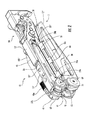
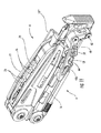
- the multipurpose tool 10 may be configured such that the handles 12 are adapted for relative movement between an open position as shown in FIG. 1 and a closed position as shown in FIG. 2 and discussed hereinafter.
- the multipurpose tool 10 has a compact form factor in the closed position so as to facilitate transport and storage of the multipurpose tool. While the multipurpose tool 10 is more expansive in the open position, one or more of the tools of the multipurpose tool are accessible and capable of being utilized in the open position, even though those same tool(s) are stowed and generally inaccessible in the closed position.
- the multipurpose tool 10 may include first 12' and second 12" handles that are respectively connected to the opposed first jaw 13' and second jaw 13" of a tool 14 which may together define a pair of pivotable pliers.
- the embodiment of the tool 14 illustrated in FIG. 1 includes needle nose pliers 17a and regular pliers 17b.
- the handles 12 may be moved toward one another to a position shown in FIG. 1 in order to close the jaws 13 of the pliers and away from one another in order to open the jaws of the pliers.
- the tool 14 may further comprise receiving apertures 15', 15" defined in one or both of the jaws 13.
- the receiving apertures 15 may be configured to receive an accessory member.
- the receiving apertures 15 may be threaded to receive and engage a barrel cleaning rod used to clean the barrel of a firearm, although various other accessory members may be received by the receiving aperture, and various other types of connectors may be employed.
- the multipurpose tool 10 may include a crimping aperture 17b' defined between the first jaw 13' and the second jaw 13" of the pliers instead of the regular pliers.
- the crimping aperture 17b' may be sized and shaped to crimp a blasting cap useable for insertion into C4 or other explosives for demolition purposes.
- the multipurpose tool 10 may comprise features which are useful for demolition experts.
- the multipurpose tool 10 can include a variety of tools. Although not heretofore described, the pliers can also include wire cutters and/or wire strippers, if desired. Additionally, the multipurpose tool 10 of one embodiment includes a knife blade 20 (see FIG. 2 ) and a bit driver 22 (see FIG. 1 ) carried by one of the handles 12. One of the handles may also carry a saw blade and/or other tools, such as a bottle opener, can opener, file, razor, gut hook or the like. With reference to the illustrated embodiment, the knife blade 20 can be pivotally connected to one of the handles 12 so as to be unfolded to a deployed position, particularly in instances in which the multipurpose tool 10 is in the closed configuration.
- bit driver 22 defines a bit chamber 22a that is sized and shaped to snugly receive corresponding bits 23, such as the Philips head screwdriver bit 23"' which is illustrated as received in the bit driver.
- bits 23 such as the Philips head screwdriver bit 23"' which is illustrated as received in the bit driver.
- the bit driver 22 may be defined in one end 12b of one of the handles 12, such as the end of the second handle 12" opposite the pivotable connection with the jaws 13', 13".
- the bit driver 22 may receive a wide variety of bits 23 including screwdriver bits, torx bits, hex bits, Robertson bits, etc.
- bit release member may alternatively comprise an integral part of the bit retention spring.
- bit release member could comprise one or more extensions of the catch 22c extending on one or both sides of the bit 23"', which could be depressed by the user to release the bit.
- the carabiner 24 defines an opening 32 into an engagement aperture 34 with the engagement aperture being accessible through both the first 26a and second 26b sidewalls.
- the object to which the multipurpose tool 10 is desirably attached may be inserted through the opening 32 into the engagement aperture 34 such that the carabiner 24 is effectively clipped to the object.
- the carabiner 24 can also include a gate 36 that extends across the opening 32 defined by the carabiner. While the carabiner 24 can include a variety of gates, the carabiner of one embodiment includes a gate 36 that is pivotally connected, at one end, to the body member 30, as illustrated.
- the gate 36 may be spring loaded so as to close the opening 32 in the absence of any applied force.
- the gate 36 can be pivotally connected to the body member 30 in various manners, the gate of the illustrated embodiment is a rectangular hoop that is pivotally connected to a first extension 30a of the body member 30. Alternatively, the gate 36 could pivotally connect to the first handle 12' directly.
- first 26a and second 26b sidewalls are spaced from one another, one or more portions of the first and second sidewalls may be interconnected.
- portions of the first 26a and second 26b sidewalls proximate the opening 32 defined by the carabiner 24 may be interconnected as indicated by interconnect 38.
- Medial portions of the first 26a and second 26b sidewalls may also be interconnected with interconnect 40, albeit at some distance spaced apart from the carabiner 24.
- other portions of the first and second sidewalls may be free of any direct connection.
- the carabiner 24 may have various orientations relative to the first handle 12' and, in turn, relative to the multipurpose tool 10, the carabiner of the illustrated embodiment is configured such that the opening 32 defined by the carabiner faces inwardly, i.e., faces toward the second handle 12", in instances in which the multipurpose tool is in the open position as shown in FIG. 1 .
- the transition of the multipurpose tool 10 from the open position to a closed position as shown in FIG. 2 repositions the carabiner 24 such that the opening 32 defined by the carabiner now faces outwardly, i.e., faces away from the second handle 12", so as to be more easily accessed by the user.
- the carabiner 24 may also include an integral bottle opener.
- the carabiner may include an inwardly turned lip 25 proximate the opening 32 defined by the carabiner.
- the lip 25 may be a portion of or proximate to interconnect 38.
- the bottle cap In order to open a bottle, the bottle cap may be inserted through the opening 32, thereby displacing the gate 36, such that the lip engages the bottle cap and permits the transfer of force thereto by the user.
- the first handle 12' and the above-mentioned body member 30 may provide additional functionality to the multipurpose tool 10. As illustrated in FIGS. 7 and 8 , the body member 30 may be connected to one or both of the first 26a and second 26b sidewalls of the first handle 12' by being inserted therebetween.
- the first handle 12' and the body member 30 may thereby define a hook configuration (see, e.g. FIG. 7 ) comprising a pocket 42 (see FIG. 8 ) defined between the first handle and the body member.
- a blade 44 may thereby be positioned and supported within the pocket 42, and may be removable from the pocket (see FIG. 12 ).
- the blade 44 may comprise a single piece of metal or other material, or may alternatively comprise a multipiece assembly.
- a retaining member such as a screw or other similar device may extend at least partially through the blade and at least partially through the first handle 12' or the body member 30.
- a screw may extend through a hole 45 (see FIG. 4 ) defined in the second sidewall 26b of the first handle 12' to retain the blade 44 in the pocket 42.
- the body member 30 may also define an actuation extension 30c.
- the actuation extension may define a member which protrudes generally perpendicularly to the handle 12' to which it is attached.
- the actuation extension 30c may be useful as a lever or hook for manipulating various objects.
- the actuation extension 30c may be configured and used to engage a bolt mechanism of a firearm such as when the firearm jams. In terms of this configuration, the actuation extension 30c may generally taper to a rounded tip.
- Various other uses as would be known by one having skill in the art are also possible.
- a portion of the body member 30 such as the actuation extension 30c may overlap with second handle 12" such that the body member intersects the axis along which the bit driver 22 receives bits 23 when the multipurpose tool 10 is in the closed position, as illustrated.
- the bit 23'" may be prevented from falling out of the bit chamber 22a of the bit driver 22 even during extreme hammering using the impact surface 30b of the multipurpose tool when the multipurpose tool 10 is in the closed position.
- Such a configuration also allows the actuation extension 30c to generally overlap with the second handle 12" when the multipurpose tool is in the closed position, such that the multipurpose tool defines a relatively compact configuration.
- the actuation extension 30c and/or the blade 44 may be facilitated by providing the impact surface 30b with one or more grip enhancing elements, such as ribs 46, configured to enhance friction during use of the multipurpose tool 10.
- grip enhancing elements such as ribs 46
- the user may grasp the multipurpose tool such that the user positions his thumb on the ribs 46 on the impact surface 30b to enhance grip in some situations.
- the ribs 46 may help prevent the impact surface 30b from slipping off of an object when the multipurpose tool 10 is being used as a hammer on the object as described above.
- the first elongate member 48 is provided with splines at the proximal end 48a which facilitate a threaded connection between the first elongate member and the first base member 49.
- an elongate member 48, 50 is integral with a respective base member 49, 51, as is the case with the illustrated second elongate member, the entirety of the elongate member and base member may be removed by removing a respective end screw 68, 69.
- One of the end screws 68, 69 may secure to a pin member with a stepped shoulder portion within the multipurpose tool 10, wherein the stepped shoulder portion is configured to retain the remainder of the tools and other components attached to the pin (other than the respective elongate member 48, 50) even when the respective end screw is removed.
- the elongate members 48, 50 are removable from the respective base members 49, 51, other tools may be connected to the base members.
- a user may select the type of tools connected to the base members depending on the type of use the multipurpose tool 10 will serve.
- the base members 49, 51 are in turn connected to respective handles 12, which may comprise either of the first handle 12' or the second handle 12".
- Each base member 49, 51 comprises a cam surface 53, 55 and may further comprise one or more detents 57, 59.
- Spring followers 61, 63 may be defined by the handles 12', 12".
- the spring followers 61, 63 may comprise cantilevered portions of the handles 12', 12".
- the spring followers 61, 63 are configured to contact the respective cam surfaces 53, 55 as the base members 49, 51 rotate about respective axes in order to extend the elongate members 48, 50 to operational positions from storage positions, as will be explained below.
- the axes about which the elongate members 48, 50 rotate may be common with one or both of the axes about which the handles 12 rotate.
- the first elongate member 48 comprises a punch which may comprise a blunt surface 48b (see, e.g. FIGS. 1 and 11 ) or a sharpened tip 48b' (see, e.g. FIGS. 2 and 3 ) at a distal end.
- the first elongate member 48 may be used to create holes in various objects or may be used to manipulate objects which may otherwise be difficult to access, such as certain internal parts of a firearm.
- the first elongate member 48 may be useful to disassemble a firearm.
- the first elongate member 48 may be useable to punch a hole in an explosive such as C4, in order to insert a blasting cap therein during preparation of explosives for demolition, particularly when the first elongate member comprises a sharpened tip 48b'.
- the second elongate member 50 may comprise a blade edge 50c extending at least partially between the proximal end 50a and a distal end 50b of the of the second elongate member. The second elongate member 50 may thus be useful for scraping or other sim ilar functions.
- the second elongate member 50 may comprise a material which is relatively softer than the material forming the object being scraped, such as a second elongate member 50 formed of bronze or a bronze alloy for scraping a bolt mechanism or other portion of a firearm formed of steel or the like.
- the second elongate member 50 may thereby be useful to scrape carbon buildup off of the bolt mechanism or other component substantially without damaging the firearm, and may thereafter be replaced when needed, as described above.
- various other uses of the elongate members 48, 50 and various other types of elongate members would be known by one having skill in the art.
- the base member 51 may comprise first 59a and second 59b detent members on either sides of the cam surface 55.
- the second elongate member 50 is folded such that the multipurpose tool 10 defines a compact configuration.
- the spring follower 63 engages the first detent 59a, which thereby provides a force on the base member 51 which tends to retain the second elongate member 50 in the storage position.
- the user when the user wants to use the second elongate member 50, the user will grasp the second elongate member in order to rotate the second elongate member in a first direction. In doing so, this will cause the base member 51 to also rotate in the first direction. Thereby, the spring follower 63 will come out of contact with the first detent 59a and begin contacting the cam surface 55.
- the cam surface 55 may comprise a first radius R 1 which is greater than a first detent radius R 0 . Accordingly, the spring follower 63 must be displaced further in order to rotate the base member 51 such that the first detent 59a comes out of contact with the spring follower. This additional force may tend to avoid accidental opening of the second elongate member 50.
- the spring force may remain constant if the second radius R 2 and third radius R 3 further defined by the cam surfaces 55 are equal to the first radius R 1 .
- the second radius R 2 may be less than the first radius R 1 and the third radius R 3 , and thus the effort required to rotate the second elongate member 50 will initially be reduced, but then will increase as the third radius along the cam surface 55 comes into contact with the spring follower 63.
- the spring follower 63 will come into contact with the second detent 59b when the second elongate member 50 reaches the operational position, as shown in FIG. 9 .
- the second elongate member 50 When in the operational position, the second elongate member 50 may be prevented from rotating further in the first direction by contact between a stop surface 59c and the spring follower 63 in a direction whereby the spring follower substantially resists displacement, such as perpendicular to the direction whereby the spring follower applies a force to the second detent 59b.
- the stop surface 59c may be defined by the proximal end 50a of the second elongate member, or may alternatively be defined by the base member 51.
- a gap 67 may be formed between a portion of the spring follower 63 and the second detent 59b of the base member 51 when the second elongate member 50 is in the operational position.
- the gap 67 may exist due to the stop surface 59c being formed such that the stop surface contacts the end of the spring follower 63 and prevents the base member 51 from rotating to the point where the second detent 59b is parallel with the portion of the spring follower that the second detent contacts.
- the second elongate member 50 may be biased such that the stop surface 59c will be forced into contact with the end of the spring member 63.
- the spring follower may be parallel to the second detent when the stop surface contacts the end of the spring follower such that no gap is formed between the spring follower and the second detent when the second elongate member is in the operational position.
- the multipurpose tool 10 can include a bit driver 22 for engaging corresponding bits 23, such as screwdriver bits, torx bits, hex bits, Robertson bits, etc..
- the multipurpose tool of one embodiment is configured to store at least one bit in instances in which the bit is not engaged by the bit driver.
- extra bits i.e., bits that are not currently engaged by the bit driver, can be stored by the multipurpose tool 10 itself in order to avoid misplacement of the extra bits.
- a sleeve 56 may be coupled to a first side A (see sides A and B defined in FIG.
- the sleeve 56 may comprise an integral part of the first handle 12' in some embodiments.
- the sleeve 56 is illustrated as being defined by a projection extending from the first handle 12', which is bent or otherwise formed into an angled member configured to receive a bit.
- the sleeve 56 may be formed partially or entirely from the first handle 12', which may reduce the weight, complexity, and/or cost of the multipurpose tool 10.
- the sleeve 56 may be configured to substantially prevent movement of the removable bit 23' in a plurality of directions other than a first axial direction and a second axial direction along the longitudinal axis of the sleeve.
- a bit stop may be positioned along the axis and configured to limit travel of the removable bit 23' in the first axial direction.
- the bit stop may comprise an integral part of the sleeve 56, a separate member, or it may alternatively comprise the first base member 49.
- a displaceable button 58 may be configured to selectively limit movement of the removable bit 23' in the sleeve 56 in the second axial direction along the axis.
- the displaceable button 58 may be moveable between a retracted (i.e.
- the multipurpose tool 10 may further comprise a clip 60 coupled to the first handle 12'.
- the clip 60 may be useful for attaching the multipurpose tool 10 to a belt, pocket, or other object.
- the clip 60 may comprise a titanium material, which resists bending while avoiding adding significant weight to the multipurpose tool 10. Additionally, the clip 60 may also be removable in order decrease the overall dimensions and weight of the multipurpose tool 10, or to allow for replacement of the clip in the unlikely event that the clip is damaged. Further, the clip 60 may comprise single piece of material or multiple pieces of material.
- the clip defines a bit aperture 62 substantially coaxial with longitudinal axis defined by the sleeve 56.
- the bit aperture 62 may thus be configured to receive the removable bit 23' during insertion of the removable bit into the sleeve 56 and during removal of the removable bit from the sleeve.
- the clip 60 may further comprise a button cutout 64 configured to facilitate access to the displaceable button 58, and thus facilitate removal and insertion of the removable bit 23'.
- the multipurpose tool 10 may further comprise a second sleeve 66 coupled to the second side B, substantially opposite to the first side A, of the first handle 12' and defining a second longitudinal axis substantially parallel with the longitudinal axis of the sleeve 56.
- the second sleeve 66 may also be integral with the first handle 12' as described above.
- the second sleeve 66 is configured to receive a second removable bit 23".
- the displaceable button 58 may be configured to limit movement of the second removable bit 23" along the second longitudinal axis when the displaceable button is in the retracted position and the extended position.
- the displaceable button 58 may allow movement of the second removable bit 23" along the second longitudinal axis when the displaceable button is in a second extended position wherein the displaceable button is displaced in a direction generally from side B toward side A past the extended position.
- both the removable bit 23' and the second removable bit 23" may be retained in the respective sleeves 56, 66.
- the displaceable button 58 is moved to the retracted position, the removable bit 23' may be removed from the sleeve 56, whereas the second removable bit 23" will be retained in the second sleeve 66 by the displaceable button.
- the displaceable button 58 is moved to the second extended position, the second removable bit 23" may be removed from the second sleeve 66, whereas the removable bit 23' will be retained in the sleeve 56 by the displaceable button. Accordingly, access to the bits 23 may be selectively controlled by selecting the position of the displaceable button 58.
- FIG. 12 illustrates an exploded view of the multipurpose tool 10 with the first handle 12' removed for clarity purposes.
- one embodiment of the multipurpose tool 10 uses a spring 70 in conjunction with the displaceable button 58.
- the spring 70 is positioned such that it is retained in place by the body member 30 and the first handle 12'.
- first 70a and second 70b prongs of the spring 70 wrap around opposite sides of the body member 30.
- FIG. 13 illustrates the interaction of the spring with the displaceable button when the displaceable button is in the extended position.
- the other parts of the multipurpose tool 10 have been removed in this view for clarity purposes.
- the first prong 70a engages a first inner groove 58a defined in the displaceable button 58 and the second prong 70a engages a second inner groove 58b defined in the displaceable button.
- the first 70a and second 70b prongs thus interact with the first 58a and second 58b inner grooves to retain the displaceable button in the extended position.
- the multipurpose tool 10 includes empty space opposite the displaceable button 58 from the spring 70 within the first handle 12' which allows the first 70a and second 70b prongs to deflect when the displaceable button is pushed along its longitudinal axis.
- the displaceable button 58 may be moved to either of the retracted position or the second extended position, as described above.
- the user would push the displaceable button 58 generally to the left along the longitudinal axis of the displaceable button, as viewed from the perspectives illustrated in FIGS. 12 and 13 .
- the first prong 70a deflects as it is forced out of the first inner groove 58a and then engages the first outer groove 58c.
- the second prong 70b deflects as it is forced out of the second inner groove 58b and then rests on the center cylindrical portion 58e of the displaceable button 58.
- the spring 70 essentially remains stationary with the exception of the deflections of the first 70a and second 70b prongs towards and away from the displaceable button 58 which deflect as they move in and out of the grooves 58a-d.
- the spring 70 is generally restrained from other movement due to each prong 70a, 70b being positioned between the body member 30 and the first handle 12'.
- the bit 23' may be removed or inserted into the sleeve 56. Thereafter it may be desirable to restrain the bit 23' in the sleeve 56.
- the displaceable button 58 would be pushed by the user back to the extended position, generally to the right along the longitudinal axis of the displaceable button 58 as illustrated in FIG. 12 and 13 , whereby the first prong 70a moves from the first outer groove 58c back to the first inner groove 58a, and the second prong 70b slides along the center cylindrical portion 58e and returns to the second inner groove 58b.
- the user pushes the displaceable button 58 further to the right along the longitudinal axis of the displaceable button 58, in terms of the perspective illustrated in FIGS. 12 and 13 , to reach the second extended position.
- the displaceable button 58 travels from the extended position to the second extended position, the second prong 70b will deflect as it is forced out of the second inner groove 58b, and then engage the second outer groove 58d.
- the first prong 70a deflects as it is forced out of the first inner groove 58a and then rests on the center cylindrical portion 58e of the displaceable button 58.
- the bit 23" may be either removed or inserted into the second sleeve 66.
- the user pushes on the button generally to the left along the longitudinal axis of the displaceable button, such that the first prong 70a returns to the first inner groove 58a, and the second prong 70b returns to the second inner groove 58b.
- the displaceable button 58 may comprise two additional features which were not discussed above.
- One such feature is that the first outer groove 58c and the second outer groove 58d respectively comprise first 58c' and second 58d' flat end surfaces.
- the flat end surfaces 58c', 58d' are configured to prevent the displaceable button 58 from extending past the retracted and second extended positions whereby the displaceable button could possibly fall out of the multipurpose tool 10.
- the first 70a and second 70b prongs contact the flat end surfaces 58c', 58d' and stop, as opposed to deflecting and allowing the displaceable button 58 to move further. This is in contrast to the generally tapered shapes defined by the other portions of the grooves 58a-d which allow the movement described above.
- the second additional feature is that the displaceable button 58 may be easier to move from the retracted and second extended positions to the extended position than it is to move the displaceable button out of the extended position. This is because when the displaceable button 58 is in the extended position, both the first prong 70a and the second prong 70b engage a respective groove 58a, 58b in the displaceable button. However, when the displaceable button 58 is in either of the retracted or second extended position, the prongs will only engage one groove.
- the displaceable button 58 when the displaceable button 58 is in the retracted position, only the first prong 70a engages a groove (the first outer groove 58c), whereas the second prong 70b will rest on the center cylindrical portion 58e, and thereby does not add significant additional resistance to movement of the displaceable button.
- the displaceable button 58 when the displaceable button 58 is in the second extended position, only the second prong 70b engages a groove (the second outer groove 58d), whereas the first prong 70a will rest on the center cylindrical portion 58e, and thereby does not add significant additional resistance to movement of the displaceable button.
- the displaceable button 58 may advantageously be more difficult to move out of the extended position, which may be preferable because the extended position retains both of the bits 23', 23" in the respective sleeves 56, 66.
- the multipurpose tool 10 may comprise additional storage for removable bits.
- removable bits are broadly defined to include a variety of tools and items which may be selectively held by the multipurpose tool.
- removable bits can include the illustrated bits 23, though other items such as fire starter kits, compasses, and other tools and items which can be selectively held by the multipurpose tool 10 are included within the meaning of this term.
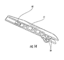
- one embodiment of the multipurpose tool 10 includes a handle cover 72 coupled to the second handle 12".
- the handle cover 72 defines an ergonomic shape which may make the multipurpose tool 10 more comfortable to use.
- the handle cover 72 may define a longitudinal channel 74 configured to receive a removable bit.
- the handle cover 72 and the removable bit may collectively define a handgrip when the removable bit is received in the longitudinal channel 74.
- the handle cover 72 may define a handgrip by itself.
- the handle cover 72 may also comprise one or more fingers 76 which extend into the longitudinal channel 74.
- the fingers 76 are configured to engage the removable bit to selectively retain the removable bit therein by providing an interference fit with the removable fit or acting as spring elements which apply a spring force to the removable bit to hold it therein.
- the handle cover 72 may be coupled to the second handle 12" in a variety of manners.
- the handle cover 72 is coupled to the second handle 12" using a configuration which simplifies attachment while providing a substantially secure connection.
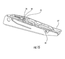
- the second handle 12" comprises an integral tang 78 which is displaced from a corresponding aperture 80 in the second handle and extends at an angle outwardly from the second handle.
- the handle cover 72 comprises a recess 82 configured to receive the tang 78.
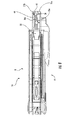
- the coupling of the handle cover 72 to the second handle 12" is shown in the sectional view illustrated in FIG. 15 .
- the handle cover 72 is at least partially coupled to the second handle 12".
- a second point of attachment such as a bolt extending through the handle cover 72 and the second handle 12" could further secure the handle cover to the handle, such as through one or more holes 84 in the handle cover. Accordingly, a secure attachment of the handle cover 72 to the second handle 12" may be effectuated.
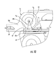
- the multipurpose tool 10 may comprise a latch 86 configured to selectively retain the multipurpose tool in the closed position, as illustrated in FIG. 16 .
- the latch 86 selectively couples the first handle 12' to the second handle 12" to thereby hold the multipurpose tool 10 in the closed configuration.
- the illustrated embodiment of the latch 86 attaches to and pivots about a retaining member 88, and which may comprise a screw or pin in some embodiments.
- the retaining member 88 also holds the blade 44 in place, although in other embodiments the retaining member may couple other tools to the first handle 12'.
- the latch 86 comprises an end tab 86b which engages the end 12b of the second handle 12".
- the latch 86 and/or the end 12b of the second handle 12" may deflect slightly to allow the latch and the end of the second handle to interfere such that the latch securely engages the end of the second handle to thereby resist accidental opening of the multipurpose tool 10.
- the latch 86 comprises a single bent piece of metal, such as a bent piece of sheet metal. Accordingly, the latch 86 may define a lightweight structure with simplified construction.
- the latch 86 may be secured and released by one hand. For example, the user may close the latch 86 by squeezing the latch to thereby apply pressure to a main arm 86a of the latch. Thereafter, to allow the multipurpose tool 10 to open, the user may flick the latch 86 open with the nail side of the thumb b to thereby apply a force to a end tab 86b of the latch, which releases it. Accordingly, operation of the latch 86 may be simplified while providing a secure way to retain the multipurpose tool 10 in the closed position when desired.
Landscapes
- Engineering & Computer Science (AREA)
- Mechanical Engineering (AREA)
- Knives (AREA)
- Percussive Tools And Related Accessories (AREA)
- Scissors And Nippers (AREA)
Priority Applications (1)
| Application Number | Priority Date | Filing Date | Title |
|---|---|---|---|
| PL10195325T PL2335882T3 (pl) | 2009-12-18 | 2010-12-16 | Narzędzie wielofunkcyjne |
Applications Claiming Priority (1)
| Application Number | Priority Date | Filing Date | Title |
|---|---|---|---|
| US12/642,227 US8166850B2 (en) | 2009-12-18 | 2009-12-18 | Multipurpose tool |
Publications (3)
| Publication Number | Publication Date |
|---|---|
| EP2335882A2 true EP2335882A2 (de) | 2011-06-22 |
| EP2335882A3 EP2335882A3 (de) | 2014-07-16 |
| EP2335882B1 EP2335882B1 (de) | 2018-09-26 |
Family
ID=43858297
Family Applications (1)
| Application Number | Title | Priority Date | Filing Date |
|---|---|---|---|
| EP10195325.5A Active EP2335882B1 (de) | 2009-12-18 | 2010-12-16 | Mehrzweckwerkzeug |
Country Status (8)
| Country | Link |
|---|---|
| US (4) | US8166850B2 (de) |
| EP (1) | EP2335882B1 (de) |
| AU (1) | AU2010257219B2 (de) |
| CA (1) | CA2725491C (de) |
| DK (1) | DK2335882T3 (de) |
| ES (1) | ES2694235T3 (de) |
| PL (1) | PL2335882T3 (de) |
| ZA (1) | ZA201009084B (de) |
Cited By (1)
| Publication number | Priority date | Publication date | Assignee | Title |
|---|---|---|---|---|
| WO2016160845A1 (en) * | 2015-04-01 | 2016-10-06 | Fiskars Brands, Inc. | Multi-function tool |
Families Citing this family (29)
| Publication number | Priority date | Publication date | Assignee | Title |
|---|---|---|---|---|
| US20110314719A1 (en) * | 2010-01-11 | 2011-12-29 | Tripp Howard R | Gun Tool |
| US9701004B2 (en) | 2011-10-25 | 2017-07-11 | Fiskars Brands, Inc. | Multi-purpose tool having removable handle for use as a hand tool |
| USD736588S1 (en) * | 2012-06-06 | 2015-08-18 | Alltrade Tools Llc | Handle for a multifunction tool |
| US9427858B2 (en) * | 2012-08-28 | 2016-08-30 | Leatherman Tool Group, Inc. | Multipurpose tool |
| USD711207S1 (en) | 2012-09-26 | 2014-08-19 | Fiskars Brands, Inc. | Multi-function tool |
| US8726561B1 (en) | 2012-12-01 | 2014-05-20 | Thurman B Hampton | Magazine spring compression tool and method |
| USD716128S1 (en) * | 2012-12-28 | 2014-10-28 | Fiskars Brands, Inc. | Multi-tool |
| US9050711B1 (en) * | 2013-04-19 | 2015-06-09 | Thomas E. Mazzarella | Multiple use fitters tool assembly |
| US9358676B2 (en) | 2013-09-20 | 2016-06-07 | Patent Store Llc | Pocket field tool |
| USD719432S1 (en) * | 2013-11-15 | 2014-12-16 | Lincoln Global, Inc. | Welding multi-tool |
| US9440346B2 (en) | 2014-01-06 | 2016-09-13 | Leatherman Tool Group, Inc. | Tool having a tool member configured for subsequent installation |
| US20150266177A1 (en) * | 2014-03-21 | 2015-09-24 | Richard Conklin | Multi-purpose locking pliers |
| USD764885S1 (en) | 2014-05-09 | 2016-08-30 | Jpj Investment Holding Corp. | Tube cutter |
| USD764252S1 (en) * | 2014-07-24 | 2016-08-23 | Revo Brand Group, Llc | Gun tool |
| USD761631S1 (en) | 2014-10-15 | 2016-07-19 | Revo Brand Group, Llc | Pistol tool |
| US9751201B2 (en) * | 2014-11-13 | 2017-09-05 | The Patent Store Llc | Landscape lighting pocket tool |
| US9682469B2 (en) | 2014-12-19 | 2017-06-20 | Leatherman Tool Group, Inc. | Multipurpose tool |
| USD754516S1 (en) * | 2014-12-19 | 2016-04-26 | Leatherman Tool Group, Inc. | Multipurpose tool |
| US9669532B1 (en) * | 2015-05-26 | 2017-06-06 | James Mayer | Ratcheting multi-tool |
| US20180345471A1 (en) * | 2017-06-06 | 2018-12-06 | Allison Sookoo | Multi-purpose electrical tool |
| US12269153B2 (en) | 2017-08-22 | 2025-04-08 | Newman Products, Llc | Multi-tool device |
| US10777919B1 (en) * | 2017-09-27 | 2020-09-15 | SeeScan, Inc. | Multifunction buried utility locating clips |
| US11358266B2 (en) | 2020-02-24 | 2022-06-14 | Puget Sound Energy, Inc. | Multi-tool for utility engineers |
| US11813728B2 (en) * | 2020-07-01 | 2023-11-14 | Sterling Hair Solutions | Multi-function nail tool |
| US11519691B2 (en) * | 2020-09-08 | 2022-12-06 | New Revo Brand Group, Llc | Firearm multi-tool and sheath |
| USD990272S1 (en) | 2020-12-28 | 2023-06-27 | Puget Sound Energy, Inc. | Multi-tool |
| USD994457S1 (en) * | 2021-03-15 | 2023-08-08 | Miaoli Feng | Multifunctional tool |
| US12529537B2 (en) * | 2023-01-13 | 2026-01-20 | Howard Kent | Unjamming multitool for firearms |
| USD1041286S1 (en) * | 2024-05-12 | 2024-09-10 | Xiaofeng FU | Multifunctional folding plier |
Family Cites Families (30)
| Publication number | Priority date | Publication date | Assignee | Title |
|---|---|---|---|---|
| US329503A (en) * | 1885-11-03 | Half to dwight c | ||
| US445972A (en) * | 1891-02-10 | John caldwell | ||
| US622197A (en) * | 1899-04-04 | Alfred g | ||
| US722899A (en) * | 1903-01-03 | 1903-03-17 | Clinton V B Reeder | Handle for tools. |
| US1109507A (en) * | 1912-08-26 | 1914-09-01 | Frederick L Bostock | Tool. |
| US1169507A (en) | 1915-04-26 | 1916-01-25 | Borden Co | Pipe-threading tool. |
| US1459531A (en) * | 1922-01-18 | 1923-06-19 | Emil J Hanson | Combination tool |
| US2005176A (en) * | 1932-12-16 | 1935-06-18 | John Le B Arbuckle | Camper's tool |
| US2539852A (en) * | 1946-03-02 | 1951-01-30 | James J Mccoy | Lever and link feed, worm-adjustable, sliding jaw wrench |
| US3094020A (en) * | 1961-06-13 | 1963-06-18 | Coy J Wise | Bolt holding tool |
| US4283805A (en) * | 1979-10-22 | 1981-08-18 | Stacy Larry C | Horse hoof pick |
| US5212844A (en) * | 1991-03-08 | 1993-05-25 | Fiskars Oy Ab | Pocket tool with retractable jaws |
| IT1258868B (it) * | 1992-10-14 | 1996-03-01 | Carmine Nicola Bandera | Coltello multiuso per il funzionamento delle armi ad avancarica. |
| US5251353A (en) | 1993-04-01 | 1993-10-12 | Lin Ming Shi | Multipurpose plier |
| US5711194A (en) * | 1995-05-26 | 1998-01-27 | Anderson; Wayne | Folding knife and interchangeable bit screwdriver |
| US5829329A (en) * | 1996-05-16 | 1998-11-03 | Sog Specialty Knives, Inc. | Hand tool with retractable jaws |
| DE69816039T2 (de) | 1998-05-18 | 2004-05-19 | Wenger S.A., Delémont | Mehrzwecktaschenwerkzeug mit einer Zange |
| US6023805A (en) | 1998-11-09 | 2000-02-15 | Lin; Hsing Tai | Tool combination having easily changeable tool members |
| DE59809819D1 (de) * | 1998-11-09 | 2003-11-06 | Victorinox Ag | Taschenwerkzeug mit Bitschlüssel |
| US6594906B1 (en) * | 2001-01-10 | 2003-07-22 | Buck Knives, Inc. | Knife with integral gated attachment |
| US20030019045A1 (en) * | 2001-07-30 | 2003-01-30 | Great Neck Saw Manufacturers, Inc. | Multi hand tool |
| US6860180B1 (en) * | 2003-10-31 | 2005-03-01 | Chien-Hsia Liao | Screwdriver provided with percussion mechanism to facilitate the unfastening and the fastening of screw |
| US7347128B2 (en) * | 2004-01-13 | 2008-03-25 | Leatherman Tool Group, Inc. | Multipurpose folding tool with tool bit holder and blade lock |
| CA2491948C (en) * | 2004-01-13 | 2009-07-14 | Leatherman Tool Group, Inc. | Multipurpose folding tool with tool bit holder and blade lock |
| US20070122574A1 (en) | 2004-01-23 | 2007-05-31 | Loggerhead Tools Llc | Storage element for tools |
| US7401432B2 (en) * | 2005-05-23 | 2008-07-22 | Perry Competition Inc. | Handgun tool and related methods |
| US7337486B2 (en) * | 2006-04-25 | 2008-03-04 | Leatherman Tool Group, Inc. | Hand tool |
| US7913591B2 (en) * | 2007-01-10 | 2011-03-29 | Leatherman Tool Group, Inc. | Multipurpose tool |
| US20090000038A1 (en) * | 2007-05-31 | 2009-01-01 | Padden Stephen J | Plier tool combination |
| US7712399B2 (en) * | 2007-10-05 | 2010-05-11 | Leatherman Tool Group, Inc. | Tool and associated bit driver |
-
2009
- 2009-12-18 US US12/642,227 patent/US8166850B2/en active Active
-
2010
- 2010-12-15 AU AU2010257219A patent/AU2010257219B2/en active Active
- 2010-12-15 CA CA2725491A patent/CA2725491C/en active Active
- 2010-12-16 EP EP10195325.5A patent/EP2335882B1/de active Active
- 2010-12-16 ES ES10195325.5T patent/ES2694235T3/es active Active
- 2010-12-16 PL PL10195325T patent/PL2335882T3/pl unknown
- 2010-12-16 DK DK10195325.5T patent/DK2335882T3/en active
- 2010-12-17 ZA ZA2010/09084A patent/ZA201009084B/en unknown
-
2012
- 2012-04-30 US US13/460,075 patent/US9138881B2/en active Active
-
2015
- 2015-09-21 US US14/860,189 patent/US10442068B2/en active Active
-
2019
- 2019-10-11 US US16/599,411 patent/US11458609B2/en active Active
Non-Patent Citations (1)
| Title |
|---|
| None |
Cited By (2)
| Publication number | Priority date | Publication date | Assignee | Title |
|---|---|---|---|---|
| WO2016160845A1 (en) * | 2015-04-01 | 2016-10-06 | Fiskars Brands, Inc. | Multi-function tool |
| US10265841B2 (en) | 2015-04-01 | 2019-04-23 | Fiskars Brands, Inc. | Multi-function tool |
Also Published As
| Publication number | Publication date |
|---|---|
| US20110145998A1 (en) | 2011-06-23 |
| US20160008967A1 (en) | 2016-01-14 |
| EP2335882A3 (de) | 2014-07-16 |
| US8166850B2 (en) | 2012-05-01 |
| US11458609B2 (en) | 2022-10-04 |
| AU2010257219B2 (en) | 2013-09-26 |
| DK2335882T3 (en) | 2018-11-19 |
| CA2725491C (en) | 2014-11-25 |
| ES2694235T3 (es) | 2018-12-19 |
| AU2010257219A1 (en) | 2011-07-07 |
| US9138881B2 (en) | 2015-09-22 |
| US20120227187A1 (en) | 2012-09-13 |
| PL2335882T3 (pl) | 2019-03-29 |
| ZA201009084B (en) | 2011-08-31 |
| EP2335882B1 (de) | 2018-09-26 |
| US10442068B2 (en) | 2019-10-15 |
| US20200039049A1 (en) | 2020-02-06 |
| CA2725491A1 (en) | 2011-06-18 |
Similar Documents
| Publication | Publication Date | Title |
|---|---|---|
| US11458609B2 (en) | Multipurpose tool | |
| US7712399B2 (en) | Tool and associated bit driver | |
| US9701004B2 (en) | Multi-purpose tool having removable handle for use as a hand tool | |
| CA2617478C (en) | Multipurpose tool | |
| US9095970B2 (en) | Multipurpose tool configured to facilitate access to individual tool members | |
| CN107427996B (zh) | 多功能工具 | |
| DK2324962T3 (en) | Utensil with integrated carabiner | |
| US6675419B2 (en) | Removable tool element for inclusion in a folding tool | |
| AU2018203316B2 (en) | Multipurpose tool | |
| AU2013273758B2 (en) | Multipurpose tool |
Legal Events
| Date | Code | Title | Description |
|---|---|---|---|
| PUAI | Public reference made under article 153(3) epc to a published international application that has entered the european phase |
Free format text: ORIGINAL CODE: 0009012 |
|
| AK | Designated contracting states |
Kind code of ref document: A2 Designated state(s): AL AT BE BG CH CY CZ DE DK EE ES FI FR GB GR HR HU IE IS IT LI LT LU LV MC MK MT NL NO PL PT RO RS SE SI SK SM TR |
|
| AX | Request for extension of the european patent |
Extension state: BA ME |
|
| PUAL | Search report despatched |
Free format text: ORIGINAL CODE: 0009013 |
|
| AK | Designated contracting states |
Kind code of ref document: A3 Designated state(s): AL AT BE BG CH CY CZ DE DK EE ES FI FR GB GR HR HU IE IS IT LI LT LU LV MC MK MT NL NO PL PT RO RS SE SI SK SM TR |
|
| AX | Request for extension of the european patent |
Extension state: BA ME |
|
| RIC1 | Information provided on ipc code assigned before grant |
Ipc: B25F 1/00 20060101AFI20140610BHEP |
|
| 17P | Request for examination filed |
Effective date: 20150114 |
|
| RBV | Designated contracting states (corrected) |
Designated state(s): AL AT BE BG CH CY CZ DE DK EE ES FI FR GB GR HR HU IE IS IT LI LT LU LV MC MK MT NL NO PL PT RO RS SE SI SK SM TR |
|
| GRAP | Despatch of communication of intention to grant a patent |
Free format text: ORIGINAL CODE: EPIDOSNIGR1 |
|
| STAA | Information on the status of an ep patent application or granted ep patent |
Free format text: STATUS: GRANT OF PATENT IS INTENDED |
|
| INTG | Intention to grant announced |
Effective date: 20180418 |
|
| GRAS | Grant fee paid |
Free format text: ORIGINAL CODE: EPIDOSNIGR3 |
|
| GRAA | (expected) grant |
Free format text: ORIGINAL CODE: 0009210 |
|
| STAA | Information on the status of an ep patent application or granted ep patent |
Free format text: STATUS: THE PATENT HAS BEEN GRANTED |
|
| AK | Designated contracting states |
Kind code of ref document: B1 Designated state(s): AL AT BE BG CH CY CZ DE DK EE ES FI FR GB GR HR HU IE IS IT LI LT LU LV MC MK MT NL NO PL PT RO RS SE SI SK SM TR |
|
| REG | Reference to a national code |
Ref country code: GB Ref legal event code: FG4D |
|
| REG | Reference to a national code |
Ref country code: CH Ref legal event code: EP |
|
| REG | Reference to a national code |
Ref country code: AT Ref legal event code: REF Ref document number: 1045441 Country of ref document: AT Kind code of ref document: T Effective date: 20181015 |
|
| REG | Reference to a national code |
Ref country code: IE Ref legal event code: FG4D |
|
| REG | Reference to a national code |
Ref country code: DE Ref legal event code: R096 Ref document number: 602010053828 Country of ref document: DE |
|
| REG | Reference to a national code |
Ref country code: DK Ref legal event code: T3 Effective date: 20181116 |
|
| REG | Reference to a national code |
Ref country code: NL Ref legal event code: FP |
|
| REG | Reference to a national code |
Ref country code: SE Ref legal event code: TRGR |
|
| REG | Reference to a national code |
Ref country code: CH Ref legal event code: NV Representative=s name: RENTSCH PARTNER AG, CH |
|
| REG | Reference to a national code |
Ref country code: ES Ref legal event code: FG2A Ref document number: 2694235 Country of ref document: ES Kind code of ref document: T3 Effective date: 20181219 |
|
| REG | Reference to a national code |
Ref country code: NO Ref legal event code: T2 Effective date: 20180926 |
|
| PG25 | Lapsed in a contracting state [announced via postgrant information from national office to epo] |
Ref country code: GR Free format text: LAPSE BECAUSE OF FAILURE TO SUBMIT A TRANSLATION OF THE DESCRIPTION OR TO PAY THE FEE WITHIN THE PRESCRIBED TIME-LIMIT Effective date: 20181227 Ref country code: RS Free format text: LAPSE BECAUSE OF FAILURE TO SUBMIT A TRANSLATION OF THE DESCRIPTION OR TO PAY THE FEE WITHIN THE PRESCRIBED TIME-LIMIT Effective date: 20180926 Ref country code: LT Free format text: LAPSE BECAUSE OF FAILURE TO SUBMIT A TRANSLATION OF THE DESCRIPTION OR TO PAY THE FEE WITHIN THE PRESCRIBED TIME-LIMIT Effective date: 20180926 Ref country code: BG Free format text: LAPSE BECAUSE OF FAILURE TO SUBMIT A TRANSLATION OF THE DESCRIPTION OR TO PAY THE FEE WITHIN THE PRESCRIBED TIME-LIMIT Effective date: 20181226 |
|
| REG | Reference to a national code |
Ref country code: LT Ref legal event code: MG4D |
|
| PG25 | Lapsed in a contracting state [announced via postgrant information from national office to epo] |
Ref country code: AL Free format text: LAPSE BECAUSE OF FAILURE TO SUBMIT A TRANSLATION OF THE DESCRIPTION OR TO PAY THE FEE WITHIN THE PRESCRIBED TIME-LIMIT Effective date: 20180926 Ref country code: LV Free format text: LAPSE BECAUSE OF FAILURE TO SUBMIT A TRANSLATION OF THE DESCRIPTION OR TO PAY THE FEE WITHIN THE PRESCRIBED TIME-LIMIT Effective date: 20180926 Ref country code: HR Free format text: LAPSE BECAUSE OF FAILURE TO SUBMIT A TRANSLATION OF THE DESCRIPTION OR TO PAY THE FEE WITHIN THE PRESCRIBED TIME-LIMIT Effective date: 20180926 |
|
| REG | Reference to a national code |
Ref country code: AT Ref legal event code: MK05 Ref document number: 1045441 Country of ref document: AT Kind code of ref document: T Effective date: 20180926 |
|
| PG25 | Lapsed in a contracting state [announced via postgrant information from national office to epo] |
Ref country code: IS Free format text: LAPSE BECAUSE OF FAILURE TO SUBMIT A TRANSLATION OF THE DESCRIPTION OR TO PAY THE FEE WITHIN THE PRESCRIBED TIME-LIMIT Effective date: 20190126 Ref country code: RO Free format text: LAPSE BECAUSE OF FAILURE TO SUBMIT A TRANSLATION OF THE DESCRIPTION OR TO PAY THE FEE WITHIN THE PRESCRIBED TIME-LIMIT Effective date: 20180926 Ref country code: CZ Free format text: LAPSE BECAUSE OF FAILURE TO SUBMIT A TRANSLATION OF THE DESCRIPTION OR TO PAY THE FEE WITHIN THE PRESCRIBED TIME-LIMIT Effective date: 20180926 Ref country code: AT Free format text: LAPSE BECAUSE OF FAILURE TO SUBMIT A TRANSLATION OF THE DESCRIPTION OR TO PAY THE FEE WITHIN THE PRESCRIBED TIME-LIMIT Effective date: 20180926 Ref country code: EE Free format text: LAPSE BECAUSE OF FAILURE TO SUBMIT A TRANSLATION OF THE DESCRIPTION OR TO PAY THE FEE WITHIN THE PRESCRIBED TIME-LIMIT Effective date: 20180926 |
|
| PG25 | Lapsed in a contracting state [announced via postgrant information from national office to epo] |
Ref country code: SM Free format text: LAPSE BECAUSE OF FAILURE TO SUBMIT A TRANSLATION OF THE DESCRIPTION OR TO PAY THE FEE WITHIN THE PRESCRIBED TIME-LIMIT Effective date: 20180926 Ref country code: SK Free format text: LAPSE BECAUSE OF FAILURE TO SUBMIT A TRANSLATION OF THE DESCRIPTION OR TO PAY THE FEE WITHIN THE PRESCRIBED TIME-LIMIT Effective date: 20180926 Ref country code: PT Free format text: LAPSE BECAUSE OF FAILURE TO SUBMIT A TRANSLATION OF THE DESCRIPTION OR TO PAY THE FEE WITHIN THE PRESCRIBED TIME-LIMIT Effective date: 20190126 |
|
| REG | Reference to a national code |
Ref country code: DE Ref legal event code: R097 Ref document number: 602010053828 Country of ref document: DE |
|
| PLBE | No opposition filed within time limit |
Free format text: ORIGINAL CODE: 0009261 |
|
| STAA | Information on the status of an ep patent application or granted ep patent |
Free format text: STATUS: NO OPPOSITION FILED WITHIN TIME LIMIT |
|
| PG25 | Lapsed in a contracting state [announced via postgrant information from national office to epo] |
Ref country code: MC Free format text: LAPSE BECAUSE OF FAILURE TO SUBMIT A TRANSLATION OF THE DESCRIPTION OR TO PAY THE FEE WITHIN THE PRESCRIBED TIME-LIMIT Effective date: 20180926 Ref country code: LU Free format text: LAPSE BECAUSE OF NON-PAYMENT OF DUE FEES Effective date: 20181216 |
|
| 26N | No opposition filed |
Effective date: 20190627 |
|
| REG | Reference to a national code |
Ref country code: IE Ref legal event code: MM4A |
|
| PG25 | Lapsed in a contracting state [announced via postgrant information from national office to epo] |
Ref country code: SI Free format text: LAPSE BECAUSE OF FAILURE TO SUBMIT A TRANSLATION OF THE DESCRIPTION OR TO PAY THE FEE WITHIN THE PRESCRIBED TIME-LIMIT Effective date: 20180926 Ref country code: IE Free format text: LAPSE BECAUSE OF NON-PAYMENT OF DUE FEES Effective date: 20181216 |
|
| PG25 | Lapsed in a contracting state [announced via postgrant information from national office to epo] |
Ref country code: MT Free format text: LAPSE BECAUSE OF NON-PAYMENT OF DUE FEES Effective date: 20181216 |
|
| PGFP | Annual fee paid to national office [announced via postgrant information from national office to epo] |
Ref country code: SE Payment date: 20191227 Year of fee payment: 10 Ref country code: FI Payment date: 20191227 Year of fee payment: 10 Ref country code: NL Payment date: 20191226 Year of fee payment: 10 |
|
| PGFP | Annual fee paid to national office [announced via postgrant information from national office to epo] |
Ref country code: IT Payment date: 20191219 Year of fee payment: 10 |
|
| PG25 | Lapsed in a contracting state [announced via postgrant information from national office to epo] |
Ref country code: TR Free format text: LAPSE BECAUSE OF FAILURE TO SUBMIT A TRANSLATION OF THE DESCRIPTION OR TO PAY THE FEE WITHIN THE PRESCRIBED TIME-LIMIT Effective date: 20180926 |
|
| PGFP | Annual fee paid to national office [announced via postgrant information from national office to epo] |
Ref country code: DK Payment date: 20191230 Year of fee payment: 10 Ref country code: NO Payment date: 20191227 Year of fee payment: 10 |
|
| PGFP | Annual fee paid to national office [announced via postgrant information from national office to epo] |
Ref country code: BE Payment date: 20191227 Year of fee payment: 10 Ref country code: CH Payment date: 20191231 Year of fee payment: 10 |
|
| PG25 | Lapsed in a contracting state [announced via postgrant information from national office to epo] |
Ref country code: MK Free format text: LAPSE BECAUSE OF NON-PAYMENT OF DUE FEES Effective date: 20180926 Ref country code: CY Free format text: LAPSE BECAUSE OF FAILURE TO SUBMIT A TRANSLATION OF THE DESCRIPTION OR TO PAY THE FEE WITHIN THE PRESCRIBED TIME-LIMIT Effective date: 20180926 Ref country code: HU Free format text: LAPSE BECAUSE OF FAILURE TO SUBMIT A TRANSLATION OF THE DESCRIPTION OR TO PAY THE FEE WITHIN THE PRESCRIBED TIME-LIMIT; INVALID AB INITIO Effective date: 20101216 |
|
| PG25 | Lapsed in a contracting state [announced via postgrant information from national office to epo] |
Ref country code: PL Free format text: LAPSE BECAUSE OF NON-PAYMENT OF DUE FEES Effective date: 20181216 |
|
| REG | Reference to a national code |
Ref country code: FI Ref legal event code: MAE |
|
| REG | Reference to a national code |
Ref country code: DK Ref legal event code: EBP Effective date: 20201231 |
|
| REG | Reference to a national code |
Ref country code: NO Ref legal event code: MMEP |
|
| PG25 | Lapsed in a contracting state [announced via postgrant information from national office to epo] |
Ref country code: FI Free format text: LAPSE BECAUSE OF NON-PAYMENT OF DUE FEES Effective date: 20201216 |
|
| REG | Reference to a national code |
Ref country code: CH Ref legal event code: PL |
|
| REG | Reference to a national code |
Ref country code: SE Ref legal event code: EUG |
|
| REG | Reference to a national code |
Ref country code: NL Ref legal event code: MM Effective date: 20210101 |
|
| REG | Reference to a national code |
Ref country code: BE Ref legal event code: MM Effective date: 20201231 |
|
| PG25 | Lapsed in a contracting state [announced via postgrant information from national office to epo] |
Ref country code: NL Free format text: LAPSE BECAUSE OF NON-PAYMENT OF DUE FEES Effective date: 20210101 |
|
| PG25 | Lapsed in a contracting state [announced via postgrant information from national office to epo] |
Ref country code: IT Free format text: LAPSE BECAUSE OF NON-PAYMENT OF DUE FEES Effective date: 20201216 |
|
| PG25 | Lapsed in a contracting state [announced via postgrant information from national office to epo] |
Ref country code: NO Free format text: LAPSE BECAUSE OF NON-PAYMENT OF DUE FEES Effective date: 20201231 Ref country code: CH Free format text: LAPSE BECAUSE OF NON-PAYMENT OF DUE FEES Effective date: 20201231 Ref country code: LI Free format text: LAPSE BECAUSE OF NON-PAYMENT OF DUE FEES Effective date: 20201231 Ref country code: SE Free format text: LAPSE BECAUSE OF NON-PAYMENT OF DUE FEES Effective date: 20201217 |
|
| PG25 | Lapsed in a contracting state [announced via postgrant information from national office to epo] |
Ref country code: DK Free format text: LAPSE BECAUSE OF NON-PAYMENT OF DUE FEES Effective date: 20201231 |
|
| PG25 | Lapsed in a contracting state [announced via postgrant information from national office to epo] |
Ref country code: BE Free format text: LAPSE BECAUSE OF NON-PAYMENT OF DUE FEES Effective date: 20201231 |
|
| PGFP | Annual fee paid to national office [announced via postgrant information from national office to epo] |
Ref country code: GB Payment date: 20251229 Year of fee payment: 16 |
|
| PGFP | Annual fee paid to national office [announced via postgrant information from national office to epo] |
Ref country code: FR Payment date: 20251226 Year of fee payment: 16 |
|
| PGFP | Annual fee paid to national office [announced via postgrant information from national office to epo] |
Ref country code: ES Payment date: 20260102 Year of fee payment: 16 |
|
| PGFP | Annual fee paid to national office [announced via postgrant information from national office to epo] |
Ref country code: DE Payment date: 20251229 Year of fee payment: 16 |