EP2335849A1 - Methods for processing nanostructured ferritic alloys and articles produced thereby - Google Patents
Methods for processing nanostructured ferritic alloys and articles produced thereby Download PDFInfo
- Publication number
- EP2335849A1 EP2335849A1 EP10194098A EP10194098A EP2335849A1 EP 2335849 A1 EP2335849 A1 EP 2335849A1 EP 10194098 A EP10194098 A EP 10194098A EP 10194098 A EP10194098 A EP 10194098A EP 2335849 A1 EP2335849 A1 EP 2335849A1
- Authority
- EP
- European Patent Office
- Prior art keywords
- article
- oxide
- alloy
- nanostructured ferritic
- nfa
- Prior art date
- Legal status (The legal status is an assumption and is not a legal conclusion. Google has not performed a legal analysis and makes no representation as to the accuracy of the status listed.)
- Withdrawn
Links
Images
Classifications
-
- B—PERFORMING OPERATIONS; TRANSPORTING
- B22—CASTING; POWDER METALLURGY
- B22F—WORKING METALLIC POWDER; MANUFACTURE OF ARTICLES FROM METALLIC POWDER; MAKING METALLIC POWDER; APPARATUS OR DEVICES SPECIALLY ADAPTED FOR METALLIC POWDER
- B22F5/00—Manufacture of workpieces or articles from metallic powder characterised by the special shape of the product
-
- B—PERFORMING OPERATIONS; TRANSPORTING
- B22—CASTING; POWDER METALLURGY
- B22F—WORKING METALLIC POWDER; MANUFACTURE OF ARTICLES FROM METALLIC POWDER; MAKING METALLIC POWDER; APPARATUS OR DEVICES SPECIALLY ADAPTED FOR METALLIC POWDER
- B22F3/00—Manufacture of workpieces or articles from metallic powder characterised by the manner of compacting or sintering; Apparatus specially adapted therefor ; Presses and furnaces
- B22F3/12—Both compacting and sintering
- B22F3/14—Both compacting and sintering simultaneously
- B22F3/15—Hot isostatic pressing
-
- B—PERFORMING OPERATIONS; TRANSPORTING
- B22—CASTING; POWDER METALLURGY
- B22F—WORKING METALLIC POWDER; MANUFACTURE OF ARTICLES FROM METALLIC POWDER; MAKING METALLIC POWDER; APPARATUS OR DEVICES SPECIALLY ADAPTED FOR METALLIC POWDER
- B22F3/00—Manufacture of workpieces or articles from metallic powder characterised by the manner of compacting or sintering; Apparatus specially adapted therefor ; Presses and furnaces
- B22F3/24—After-treatment of workpieces or articles
-
- C—CHEMISTRY; METALLURGY
- C22—METALLURGY; FERROUS OR NON-FERROUS ALLOYS; TREATMENT OF ALLOYS OR NON-FERROUS METALS
- C22C—ALLOYS
- C22C33/00—Making ferrous alloys
- C22C33/02—Making ferrous alloys by powder metallurgy
- C22C33/0257—Making ferrous alloys by powder metallurgy characterised by the range of the alloying elements
- C22C33/0278—Making ferrous alloys by powder metallurgy characterised by the range of the alloying elements with at least one alloying element having a minimum content above 5%
- C22C33/0285—Making ferrous alloys by powder metallurgy characterised by the range of the alloying elements with at least one alloying element having a minimum content above 5% with Cr, Co, or Ni having a minimum content higher than 5%
-
- C—CHEMISTRY; METALLURGY
- C22—METALLURGY; FERROUS OR NON-FERROUS ALLOYS; TREATMENT OF ALLOYS OR NON-FERROUS METALS
- C22C—ALLOYS
- C22C38/00—Ferrous alloys, e.g. steel alloys
- C22C38/02—Ferrous alloys, e.g. steel alloys containing silicon
-
- C—CHEMISTRY; METALLURGY
- C22—METALLURGY; FERROUS OR NON-FERROUS ALLOYS; TREATMENT OF ALLOYS OR NON-FERROUS METALS
- C22C—ALLOYS
- C22C38/00—Ferrous alloys, e.g. steel alloys
- C22C38/04—Ferrous alloys, e.g. steel alloys containing manganese
-
- C—CHEMISTRY; METALLURGY
- C22—METALLURGY; FERROUS OR NON-FERROUS ALLOYS; TREATMENT OF ALLOYS OR NON-FERROUS METALS
- C22C—ALLOYS
- C22C38/00—Ferrous alloys, e.g. steel alloys
- C22C38/18—Ferrous alloys, e.g. steel alloys containing chromium
- C22C38/22—Ferrous alloys, e.g. steel alloys containing chromium with molybdenum or tungsten
-
- C—CHEMISTRY; METALLURGY
- C22—METALLURGY; FERROUS OR NON-FERROUS ALLOYS; TREATMENT OF ALLOYS OR NON-FERROUS METALS
- C22C—ALLOYS
- C22C38/00—Ferrous alloys, e.g. steel alloys
- C22C38/18—Ferrous alloys, e.g. steel alloys containing chromium
- C22C38/28—Ferrous alloys, e.g. steel alloys containing chromium with titanium or zirconium
-
- F—MECHANICAL ENGINEERING; LIGHTING; HEATING; WEAPONS; BLASTING
- F01—MACHINES OR ENGINES IN GENERAL; ENGINE PLANTS IN GENERAL; STEAM ENGINES
- F01D—NON-POSITIVE DISPLACEMENT MACHINES OR ENGINES, e.g. STEAM TURBINES
- F01D5/00—Blades; Blade-carrying members; Heating, heat-insulating, cooling or antivibration means on the blades or the members
- F01D5/12—Blades
- F01D5/28—Selecting particular materials; Particular measures relating thereto; Measures against erosion or corrosion
- F01D5/286—Particular treatment of blades, e.g. to increase durability or resistance against corrosion or erosion
-
- B—PERFORMING OPERATIONS; TRANSPORTING
- B22—CASTING; POWDER METALLURGY
- B22F—WORKING METALLIC POWDER; MANUFACTURE OF ARTICLES FROM METALLIC POWDER; MAKING METALLIC POWDER; APPARATUS OR DEVICES SPECIALLY ADAPTED FOR METALLIC POWDER
- B22F3/00—Manufacture of workpieces or articles from metallic powder characterised by the manner of compacting or sintering; Apparatus specially adapted therefor ; Presses and furnaces
- B22F3/24—After-treatment of workpieces or articles
- B22F2003/247—Removing material: carving, cleaning, grinding, hobbing, honing, lapping, polishing, milling, shaving, skiving, turning the surface
-
- B—PERFORMING OPERATIONS; TRANSPORTING
- B22—CASTING; POWDER METALLURGY
- B22F—WORKING METALLIC POWDER; MANUFACTURE OF ARTICLES FROM METALLIC POWDER; MAKING METALLIC POWDER; APPARATUS OR DEVICES SPECIALLY ADAPTED FOR METALLIC POWDER
- B22F2998/00—Supplementary information concerning processes or compositions relating to powder metallurgy
- B22F2998/10—Processes characterised by the sequence of their steps
-
- F—MECHANICAL ENGINEERING; LIGHTING; HEATING; WEAPONS; BLASTING
- F05—INDEXING SCHEMES RELATING TO ENGINES OR PUMPS IN VARIOUS SUBCLASSES OF CLASSES F01-F04
- F05D—INDEXING SCHEME FOR ASPECTS RELATING TO NON-POSITIVE-DISPLACEMENT MACHINES OR ENGINES, GAS-TURBINES OR JET-PROPULSION PLANTS
- F05D2230/00—Manufacture
- F05D2230/90—Coating; Surface treatment
-
- F—MECHANICAL ENGINEERING; LIGHTING; HEATING; WEAPONS; BLASTING
- F05—INDEXING SCHEMES RELATING TO ENGINES OR PUMPS IN VARIOUS SUBCLASSES OF CLASSES F01-F04
- F05D—INDEXING SCHEME FOR ASPECTS RELATING TO NON-POSITIVE-DISPLACEMENT MACHINES OR ENGINES, GAS-TURBINES OR JET-PROPULSION PLANTS
- F05D2300/00—Materials; Properties thereof
- F05D2300/50—Intrinsic material properties or characteristics
- F05D2300/502—Thermal properties
-
- Y—GENERAL TAGGING OF NEW TECHNOLOGICAL DEVELOPMENTS; GENERAL TAGGING OF CROSS-SECTIONAL TECHNOLOGIES SPANNING OVER SEVERAL SECTIONS OF THE IPC; TECHNICAL SUBJECTS COVERED BY FORMER USPC CROSS-REFERENCE ART COLLECTIONS [XRACs] AND DIGESTS
- Y02—TECHNOLOGIES OR APPLICATIONS FOR MITIGATION OR ADAPTATION AGAINST CLIMATE CHANGE
- Y02T—CLIMATE CHANGE MITIGATION TECHNOLOGIES RELATED TO TRANSPORTATION
- Y02T50/00—Aeronautics or air transport
- Y02T50/60—Efficient propulsion technologies, e.g. for aircraft
Definitions
- the present disclosure relates to nanostructured ferritic alloys (NFAs), and more particularly, methods for processing the same so that articles comprising the NFAs and so processed are suitable for use in challenging environments.
- NFAs nanostructured ferritic alloys
- Gas turbines operate in extreme environments, exposing the turbine components, especially those in the turbine hot section, to high operating temperatures and stresses. In order for the turbine components to endure these conditions, they are necessarily manufactured from a material capable of withstanding these severe conditions. Superalloys have been used in these demanding applications because they maintain their strength at up to 90% of their melting temperature and have excellent environmental resistance. Nickel-based superalloys, in particular, have been used extensively throughout gas turbine engines, e.g., in turbine blade, nozzle, wheel, spacer, disk, spool, blisk, and shroud applications. However, designs for improved gas turbine performance require alloys with even higher temperature capability.
- Nickel base superalloys used in heavy-duty turbine components require specific processing steps in order to achieve the desired mechanical properties.
- This process referred to as a cast and wrought (C&W) approach begins with three melting operations: vacuum induction melting (VIM), electroslag remelting (ESR), and vacuum arc remelting (VAR).
- VIM vacuum induction melting
- ESR electroslag remelting
- VAR vacuum arc remelting
- the initial VIM operation mixes the elements together forming the alloy of interest; however, significant impurities and macro scale chemical segregation are present.
- the subsequent ESR and VAR steps are required to produce a chemically pure, homogeneous ingot.
- the grains of the resulting VAR ingot are too coarse to yield the necessary mechanical properties.
- the ingot is broken down via a double upset and draw operation resulting in the recrystallization and refinement of the nickel base superalloy structure.
- the billet is forged and machined into its final desired shape.
- Nanostructured ferritic alloys are an emerging class of alloys that exhibit exceptional high temperature properties, thought to be derived from nanometer-sized oxide clusters that precipitate during hot consolidation following a mechanical alloying step. These oxide clusters are present to high temperatures, providing a strong, stable, microstructure during service.
- NFAs are manufactured via a different processing route. Like the C&W process, the alloy chemistry is created via a VIM operation. However, following the initial melting, the NFA is atomized and collected as solid powder particles. These powder particles are then combined with an oxide additive and milled in the presence of steel shot until the oxide addition dissolves in the metal matrix. The ESR and VAR steps are not required.
- any material may also desirably exhibit both an acceptable continuous cycle fatigue crack growth rate as well as an acceptable hold time fatigue crack growth rate.
- Such a material may also desirably be utilized for smaller turbomachinery components, e.g., discs for use in jet engines, which likely have a different set of desired or required properties.
- Any such alloy will also desirably be capable of being manufactured into the desired article utilizing a less energy intensive and/or time consuming process, than the conventional cast and wrought process.
- a formed article comprising a nanostructured ferritic alloy, wherein the article is not formed via extrusion.
- a turbomachinery component comprising a nanostructured ferritic alloy is also provided.
- a method of forming a turbomachinery component comprising a nanostructured ferritic alloy is provided. The method does not comprise extrusion.
- a method of forming a turbomachinery component comprising a nanostructured ferritic alloy comprises melting the nanostructured ferritic alloy via vacuum induction melting, atomizing the nanostructured ferritic alloy melt, sieving the atomized powder, milling the atomized powder in the presence of an oxide until the oxide is dissolved into the metal matrix, and canning and hot isostatic pressing the powder under an inert environment.
- FIG. 1 is a schematic illustration of one embodiment of the method provided herein.
- ranges are inclusive and independently combinable (e.g., ranges of "up to about 25 wt.%, or, more specifically, about 5 wt.% to about 20 wt.%,” is inclusive of the endpoints and all intermediate values of the ranges of "about 5 wt.% to about 25 wt.%,” etc.).
- the modifier "about” used in connection with a quantity is inclusive of the stated value and has the meaning dictated by the context (e.g., includes the degree of error associated with measurement of the particular quantity).
- formed articles comprising a nanostructured ferritic alloy, wherein the article is not formed via extrusion. It has now been surprisingly discovered that formed articles can be made from such alloys without an extrusion step, which is advantageous because extrusion limits the final part geometry size. That is, the extrusion step requires a cross sectional area reduction, which limits the part diameter to a size that precludes articles for use in many applications.
- the present invention includes smaller components that may be formed by extrusion, if desired.
- components for use in aerospace applications may advantageously be formed from NFAs, in which case, the NFAs may provide the components with properties desirable in such applications, and not achievable with conventional nickel-based alloys.
- the formed articles comprise at least one nanostructured ferritic alloy (NFA).
- NFAs are an emerging class of alloys comprised of a stainless steel matrix that is dispersion strengthened by a very high density, i.e., at least about 10 18 m -3 , or at least about 10 20 m -3 , or even at least about 10 22 m -3 of nm-scale, i . e .
- nanofeatures comprising Ti-O and at least one other element from the oxide used to prepare the NFA or the alloy matrix.
- NFs nanofeatures
- yttrium oxide, aluminum oxide, zirconium oxide, hafnium oxide may be used to prepare the NFA, in which case, the nanofeatures may comprise yttrium (Y), aluminum (Al), zirconium (Z), hafnium (Hf) or combinations of these.
- Transition metals such as Fe, Cr, Mo, W, Mn, Si, Nb, Al, Ni, or Ta from the alloy matrix can also participate in the creation of the nanofeatures.
- oxide dispersion strengthened (ODS) alloys generally contain refined, but larger, equilibrium oxide phases, and, the oxide additive is stable throughout the powder metallurgy process, i.e., if yttrium oxide were added to the matrix alloy, ytrrium oxide would be present after the alloying step and there would be no significant formation of the nanofeatures (NFs) described above.
- ODS oxide dispersion strengthened
- the majority, if not substantially all, of the added oxide is dissolved into the alloy matrix during powder attrition and participates in the formation of the aforementioned nanofeatures when the powder is raised in temperature during the compaction process.
- the new oxide in the NFA may comprise the transition metals present in the base alloy as well as the metallic element(s) of the initial oxide addition.
- NFA stainless steel matrix is most often a ferritic stainless steel; martensitic, duplex, and austenitic stainless steels are also potential matrix alloys. Altering the steel matrix phase may allow for improved control over environmental resistance and material ductility.
- the NFA may comprise chromium.
- Chromium can be important for ensuring corrosion resistance, and may thus be included in the NFA in amounts of at least about 5 wt%, or at least about 9 wt%. Amounts of up to about 30 wt% or up to about 20 wt% or up to about 14 wt% can be included.
- both chromium and iron, the basis of the NFA are readily available and relatively low in cost, in particular as compared to nickel-based superalloys which the NFAs may replace in some applications.
- the NFA may also desirably include amounts of titanium. Titanium may participate in the formation of the precipitated oxide, and so, amounts of titanium of from about 0.1 wt% to about 2 wt%, or from about 0.1 wt% to about 1 wt% or from about 0.1 wt% to about 0.5 wt%, are desirably included in the NFA.
- the NFA further desirably comprises the nanofeatures described above, in number densities of at least about 10 18 m -3 , or at least about 10 20 m -3 , or even at least about 10 22 m -3 .
- the composition of the nanofeature(s) will depend upon the oxide utilized to prepare the NFA and/or the alloy matrix.
- the nanofeatures comprise Ti-O and at least one of Y, Al, Zr, Hf, Fe, Cr, Mo, W, Mn, Si, Nb, Al, Ni, or Ta.
- One exemplary NFA suitable for use in the formation of the article may comprise from about 5 wt% to about 30 wt% chromium, from about 0.1 wt% to about 2 wt% titanium, from about 0 wt% to about 5 wt% molybdenum, from about 0 wt% to about 5 wt% tungsten, from about 0 wt% to about 5 wt% manganese, from about 0 wt% to about 5 wt% silicon, from about 0 wt% to about 2 wt% niobium, from about 0 wt% to about 2 wt% aluminum, from about 0 wt% to about 8 wt% nickel, from about 0 wt% to about 2 wt% tantalum, from about 0 wt% to about 0.5 wt% carbon, and from about 0 wt% to about 0.5 wt% nitrogen, with the balance being iron and incidental impurities; and a
- the NFA may comprise from about 9 wt% to about 20 wt% chromium, from about 0.1 wt% to about 1 wt% titanium, from about 0 wt% to about 4 wt% molybdenum, from about 0 wt% to about 4 wt% tungsten, from about 0 wt% to about 2.5 wt% manganese, from about 0 wt% to about 2.5 wt% silicon, from about 0 wt% to about 1 wt% niobium, from about 0 wt% to about 1 wt% aluminum, from about 0 wt% to about 4 wt% nickel, from about 0 wt% to about 1 wt% tantalum, from about 0 wt% to about 0.2 wt% carbon, and from about 0 wt% to about 0.2 wt% nitrogen, with the balance being iron and incidental impurities; and a number density of at least about 10
- the NFA may comprise from about 9 wt% to about 14 wt% chromium, from about 0.1 wt% to about 0.5 wt% titanium, from about 0 wt% to about 3 wt% molybdenum, from about 0 wt% to about 3 wt% tungsten, from about 0 wt% to about 1 wt% manganese, from about 0 wt% to about 1 wt% silicon, from about 0 wt% to about 0.5 wt% niobium, from about 0 wt% to about 0.5 wt% aluminum, from about 0 wt% to about 2 wt% nickel, from about 0 wt% to about 0.5 wt% tantalum, from about 0 wt% to about 0.1 wt% carbon, and from about 0 wt% to about 0.1 wt% nitrogen, with the balance being iron and incidental impurities; wherein the NFA
- the formed article may be any article desirably comprising the properties conferred thereto by the NFA.
- One exemplary class of articles that may find particular benefit from application of the principles described herein comprises turbomachinery components, and in particular, those that experience high temperatures during use.
- Nickel-based superalloys strengthened with a gamma prime or gamma double prime phase have conventionally been used in these applications.
- heavy duty turbine wheels strengthened with gamma double prime currently see maximum operating temperatures in the range of 1000°F to 1100°F.
- the hold time crack growth resistance of many gamma double prime strengthened nickel-based superalloys does not meet design requirements for heavy duty turbine wheels.
- efficiency gains and CO 2 reductions that can only be realized by higher operating temperatures are not achievable due to nickel-based superalloy material property limitations.
- the formed article may advantageously comprise a large, hot section component of a heavy duty gas turbine or steam turbine.
- Such articles, and wheels and spacers in particular are typically in excess of 60 inches or more in diameter and cannot be formed via extrusion.
- the formed article comprises a heavy duty turbine wheel to be manufactured from a single alloy via hot isostatic pressing, hot isostatic pressing and forging or roll compaction
- the alloy used needs to be able to withstand varying conditions based on the position within the wheel.
- the bore can be operating at temperatures up to 900°F. At this temperature, the alloy must be capable of withstanding tensile stresses of approximately 120 ksi, importantly while also exhibiting sufficient fatigue crack growth resistance in all locations.
- the article comprising the NFA can exhibit a continuous cycle fatigue crack growth rate at 1000°F at a stress intensity factor (k) of 45 ksi*in 0.5 of less than about 1.20E -4 in/cycle, or even less than about 9.03E -5 in/cycle, as measured by ASTM E647.
- the article comprising the NFA can exhibit hold time fatigue crack growth rate at 1000°F at a k of 45 ksi*in 0.5 of less than about 1.80E -3 in/hr, or even less than about 1.35E -3 in/hr, as measured by ASTM E1457.
- the articles described are not formed via conventional cast and wrought processes, and so, time savings are provided.
- the articles are not formed via a process comprising extrusion, and so, the final part size is not particularly limited.
- the components requiring the properties that can be provided by an NFA may typically be smaller than those used in heavy duty turbine applications, the components may advantageously be extruded.
- the articles provided herein can be formed by first melting the NFA via vacuum induction melting (VIM). Vacuum induction melting results in all elemental species being melted and mixed together, forming the alloy of interest. To do so, the elements of interest are charged into a vacuum induction melting furnace and heated until the mixture becomes molten. The conditions required to do so will depend upon the elements desirably utilized, and those of skill in the art will be readily able to determine the same.
- VIM vacuum induction melting
- a bottom pore vacuum induction melting system may be used, so that the molten metal falls through an inert gas atomizer.
- the atomizer may utilize any inert gas, but most often Ar, N, or He is used. In some embodiments, argon is utilized. This gas atomizer generates powder particles that cool in flight and are collected once they are completely solid and/or frozen.
- the atomized powder is then sieved to a final powder cut. Typically, such powder cuts are made in order to reduce the particle size distribution, to improve packing densities and remove any large impurities.
- the powder is transferred to an attrition vessel while continuing to maintain inert gas coverage.
- the desired oxide and steel shot is added to the attrition vessel. Any oxide may be utilized in any amount, although typically, yttrium oxide, alumina oxide, zirconium oxide, hafnium oxide are utilized in amounts of 1 wt% or less, based upon the total weight of the NFA.
- the steel shot typically 5 mm, is added such that the shot to powder ratio is about 10:1 by mass.
- the powders are then milled until the desired oxide has been dissolved into the metal matrix. The milling time may vary based upon the oxide selected, and may typically be greater than 10 hours.
- the powder is unloaded from the attritor under inert gas coverage and the steel shot is removed. Once the steel shot is removed, the powder is loaded into a container (or can) for hot isostatic pressing (HIP). The can is then evacuated at room temperature, until an acceptable leak back rate is reached. The can is then heated, e.g., to about 550°F and again evacuated, e.g., until an acceptable leak back rate is reached at temperature.
- HIP hot isostatic pressing
- the powder is then consolidated via hot isostatic pressing. More particularly, the can is hot isostatic pressed at the appropriate conditions based upon the NFA desirably consolidated, such conditions typically including a pressure of at least about 20 ksi, or even 30 ksi, at a temperature of at least about 900°C, or 1000°C, or 1100°C, or greater, for at least about 1 hour, or 2 hours, or 3 hours, or 4 hours, or greater.
- the nanostructured ferritic alloy is expected to have a density that is greater than 95% of theoretical density.
- the HIP can may be reheated to a temperature of about 1000°C, or 1100°C, or 1200°C then transferred to an open die forging press and the height of the can reduced by at least about 30%, or at least about 40%, or at least about 50%.
- the can is removed from the forging press and re-heated until the entire can is once again at a temperature of about 1000°C, or 1100°C, or 1200°C.
- the can is then transferred to the open die forging press and is upset, i.e., the height of the can reduced, by at least about 30%, or at least about 40% or at least about 50%, a second time.
- the forged material is then allowed to air cool. After forging, the nanostructured ferritic alloy has a density that is greater than 98% of theoretical density. Once cool, in some embodiments, the present articles may be machined from the forging to provide the desired article.
- the article may be formed via roll compaction.
- the powder may be fed into a rolling mill where the powder is compacted into sheets.
- the sheets of metal may then be sintered to create a dense body.
- the sintered sheet may then be subjected to multiple rolling and sintering operations.
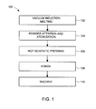
- FIG. 1 schematically illustrates one embodiment of the method provided. More particularly, method 100 comprises a first step 102 of vacuum induction melting of the elements of the NFA.
- the elements of interest are charged into a vacuum induction melting furnace and heated until the mixture becomes molten.
- a bottom pore vacuum induction melting system may be used, so that the molten metal falls through an inert gas atomizer.
- a second step 104 the molten metal is subjected to powder atomization and attrition.
- the atomization step generates powder particles that cool in flight and are collected once they are solid.
- the atomized powder is then sieved, or attrited, at step 106 [more detail here, and in particular, about the powder cuts] and the sieved powder milled in the presence of an oxide until the oxide is dissolved into the metal matrix.
- the powder is then loaded into a container, evacuated, and then consolidated via hot isostatic pressing at step 108.
- the nanostructured ferritic alloy is expected to have a density that is greater than 95% of theoretical density.
- the powder may be consolidated using roll compaction, as described above.
- the resulting consolidated billet is then optionally forged at step 110 and machined at step 112.
- the nanostructured ferritic alloy may have a density that is greater than 98% of theoretical density.
- a vacuum induction melting furnace is charged with the following composition: Fe-14Cr-0.4Ti-3W-0.5Mn-0.5Si (wt %).
- the alloy is molten and well mixed, it is atomized via argon gas. While still under inert gas coverage, the powder is sieved to a final cut size of +325/-100 and sealed in a container. The powder is transferred to an attrition vessel while continuing to maintain inert gas coverage.
- 0.25 weight percent of yttrium oxide and 5 mm steel shot is added to the attrition vessel. The steel shot is added such that the shot to powder ratio is 10:1 by mass.
- the powders are then milled for approximately 12 hours or until the yttrium oxide has been dissolved into the metal matrix.
- the powder is unloaded from the attritor under inert gas coverage and the steel shot is removed. Once the steel shot is removed, the powder is loaded into a container (or can) for hot isostatic pressing (HIP).
- the can is then evacuated at room temperature until a leak back rate of 15 microns/hour or better is reached.
- the can is then heated to 300°C and evacuated until a leak back rate of 15 microns/hour or better is reached at temperature. Once evacuated and sealed, the HIP can is then HIP'd at 30 ksi for 4 hours at a temperature of 1150°C.
- the still canned material is heated in a furnace with flowing argon to a temperature of 1150°C.
- the can is transferred to an open die forging press and the height is reduced by 50% at a displacement rate of 1 in/min.
- the can is removed from the forging press and re-heated in a furnace for one hour or until the entire can is once again at a temperature of 1150°C.
- the can is then transferred to the open die forging press and is upset by 50% a second time at a displacement rate of 1 in/min.
- the forged material is then allowed to air cool.
Landscapes
- Chemical & Material Sciences (AREA)
- Engineering & Computer Science (AREA)
- Mechanical Engineering (AREA)
- Materials Engineering (AREA)
- Metallurgy (AREA)
- Organic Chemistry (AREA)
- Manufacturing & Machinery (AREA)
- General Engineering & Computer Science (AREA)
- Powder Metallurgy (AREA)
Abstract
A formed article comprising a nanostructured ferritic alloy is provided. Advantageously, the article is not formed via extrusion, and thus, cost savings are provided. Methods are also provided for forming the article, and the articles so produced, exhibit sufficient continuous cycle fatigue crack growth resistance and hold time fatigue crack growth resistance to be utilized as turbomachinery components, and in particular, large, hot section components of a gas or steam turbine engines. In other embodiments, a turbomachinery component comprising an NFA is provided, and in some such embodiments, the turbomachinery component may be extruded.
Description
- The present disclosure relates to nanostructured ferritic alloys (NFAs), and more particularly, methods for processing the same so that articles comprising the NFAs and so processed are suitable for use in challenging environments.
- Gas turbines operate in extreme environments, exposing the turbine components, especially those in the turbine hot section, to high operating temperatures and stresses. In order for the turbine components to endure these conditions, they are necessarily manufactured from a material capable of withstanding these severe conditions. Superalloys have been used in these demanding applications because they maintain their strength at up to 90% of their melting temperature and have excellent environmental resistance. Nickel-based superalloys, in particular, have been used extensively throughout gas turbine engines, e.g., in turbine blade, nozzle, wheel, spacer, disk, spool, blisk, and shroud applications. However, designs for improved gas turbine performance require alloys with even higher temperature capability.
- Nickel base superalloys used in heavy-duty turbine components require specific processing steps in order to achieve the desired mechanical properties. This process, referred to as a cast and wrought (C&W) approach begins with three melting operations: vacuum induction melting (VIM), electroslag remelting (ESR), and vacuum arc remelting (VAR). The initial VIM operation mixes the elements together forming the alloy of interest; however, significant impurities and macro scale chemical segregation are present. The subsequent ESR and VAR steps are required to produce a chemically pure, homogeneous ingot. The grains of the resulting VAR ingot are too coarse to yield the necessary mechanical properties. As a result, the ingot is broken down via a double upset and draw operation resulting in the recrystallization and refinement of the nickel base superalloy structure. Finally the billet is forged and machined into its final desired shape.
- Nanostructured ferritic alloys (NFAs) are an emerging class of alloys that exhibit exceptional high temperature properties, thought to be derived from nanometer-sized oxide clusters that precipitate during hot consolidation following a mechanical alloying step. These oxide clusters are present to high temperatures, providing a strong, stable, microstructure during service. Unlike many nickel base superalloys that require the C&W process to be followed to obtain necessary properties, NFAs are manufactured via a different processing route. Like the C&W process, the alloy chemistry is created via a VIM operation. However, following the initial melting, the NFA is atomized and collected as solid powder particles. These powder particles are then combined with an oxide additive and milled in the presence of steel shot until the oxide addition dissolves in the metal matrix. The ESR and VAR steps are not required.
- In order for any material to be optimally useful in, e.g., large hot section components of heavy duty turbo machinery, it may also desirably exhibit both an acceptable continuous cycle fatigue crack growth rate as well as an acceptable hold time fatigue crack growth rate. Such a material may also desirably be utilized for smaller turbomachinery components, e.g., discs for use in jet engines, which likely have a different set of desired or required properties. Any such alloy will also desirably be capable of being manufactured into the desired article utilizing a less energy intensive and/or time consuming process, than the conventional cast and wrought process.
- In one aspect, there is provided a formed article comprising a nanostructured ferritic alloy, wherein the article is not formed via extrusion.
- A turbomachinery component comprising a nanostructured ferritic alloy is also provided.
- In another aspect, a method of forming a turbomachinery component comprising a nanostructured ferritic alloy is provided. The method does not comprise extrusion.
- In yet another aspect a method of forming a turbomachinery component comprising a nanostructured ferritic alloy is provided. The method comprises melting the nanostructured ferritic alloy via vacuum induction melting, atomizing the nanostructured ferritic alloy melt, sieving the atomized powder, milling the atomized powder in the presence of an oxide until the oxide is dissolved into the metal matrix, and canning and hot isostatic pressing the powder under an inert environment.
- These and other features, aspects, and advantages of the present invention will become better understood when the following detailed description is read with reference to the accompanying drawings in which like characters represent like parts throughout the drawings, wherein
-
FIG. 1 is a schematic illustration of one embodiment of the method provided herein. - Unless defined otherwise, technical and scientific terms used herein have the same meaning as is commonly understood by one of skill in the art to which this invention belongs. The terms "first", "second", and the like, as used herein do not denote any order, quantity, or importance, but rather are used to distinguish one element from another. Also, the terms "a" and "an" do not denote a limitation of quantity, but rather denote the presence of at least one of the referenced item, and the terms "front", "back", "bottom", and/or "top", unless otherwise noted, are merely used for convenience of description, and are not limited to any one position or spatial orientation. If ranges are disclosed, the endpoints of all ranges directed to the same component or property are inclusive and independently combinable (e.g., ranges of "up to about 25 wt.%, or, more specifically, about 5 wt.% to about 20 wt.%," is inclusive of the endpoints and all intermediate values of the ranges of "about 5 wt.% to about 25 wt.%," etc.). The modifier "about" used in connection with a quantity is inclusive of the stated value and has the meaning dictated by the context (e.g., includes the degree of error associated with measurement of the particular quantity).
- There are provided herein formed articles comprising a nanostructured ferritic alloy, wherein the article is not formed via extrusion. It has now been surprisingly discovered that formed articles can be made from such alloys without an extrusion step, which is advantageous because extrusion limits the final part geometry size. That is, the extrusion step requires a cross sectional area reduction, which limits the part diameter to a size that precludes articles for use in many applications.
- In other embodiments, the present invention includes smaller components that may be formed by extrusion, if desired. For example, components for use in aerospace applications may advantageously be formed from NFAs, in which case, the NFAs may provide the components with properties desirable in such applications, and not achievable with conventional nickel-based alloys.
- Whether formed by extrusion, hot isostatic pressing, hot isostatic pressing and forging, or roll compaction, the formed articles comprise at least one nanostructured ferritic alloy (NFA). NFAs are an emerging class of alloys comprised of a stainless steel matrix that is dispersion strengthened by a very high density, i.e., at least about 10 18 m-3, or at least about 1020 m-3, or even at least about 1022 m-3 of nm-scale, i.e., from about 1 nm to about 100 nm, or from about 1 nm to about 50 nm, or from about 1 nm to about 10 nm, nanofeatures (NFs) comprising Ti-O and at least one other element from the oxide used to prepare the NFA or the alloy matrix. For example, yttrium oxide, aluminum oxide, zirconium oxide, hafnium oxide may be used to prepare the NFA, in which case, the nanofeatures may comprise yttrium (Y), aluminum (Al), zirconium (Z), hafnium (Hf) or combinations of these. Transition metals, such as Fe, Cr, Mo, W, Mn, Si, Nb, Al, Ni, or Ta from the alloy matrix can also participate in the creation of the nanofeatures.
- In contrast, conventional oxide dispersion strengthened (ODS) alloys generally contain refined, but larger, equilibrium oxide phases, and, the oxide additive is stable throughout the powder metallurgy process, i.e., if yttrium oxide were added to the matrix alloy, ytrrium oxide would be present after the alloying step and there would be no significant formation of the nanofeatures (NFs) described above. In an NFA, the majority, if not substantially all, of the added oxide is dissolved into the alloy matrix during powder attrition and participates in the formation of the aforementioned nanofeatures when the powder is raised in temperature during the compaction process. As described above, the new oxide in the NFA may comprise the transition metals present in the base alloy as well as the metallic element(s) of the initial oxide addition.
- While the NFA stainless steel matrix is most often a ferritic stainless steel; martensitic, duplex, and austenitic stainless steels are also potential matrix alloys. Altering the steel matrix phase may allow for improved control over environmental resistance and material ductility.
- Any NFA can be formed into the disclosed article. Desirably, the NFA may comprise chromium. Chromium can be important for ensuring corrosion resistance, and may thus be included in the NFA in amounts of at least about 5 wt%, or at least about 9 wt%. Amounts of up to about 30 wt% or up to about 20 wt% or up to about 14 wt% can be included. Advantageously, both chromium and iron, the basis of the NFA, are readily available and relatively low in cost, in particular as compared to nickel-based superalloys which the NFAs may replace in some applications.
- The NFA may also desirably include amounts of titanium. Titanium may participate in the formation of the precipitated oxide, and so, amounts of titanium of from about 0.1 wt% to about 2 wt%, or from about 0.1 wt% to about 1 wt% or from about 0.1 wt% to about 0.5 wt%, are desirably included in the NFA.
- The NFA further desirably comprises the nanofeatures described above, in number densities of at least about 1018 m-3, or at least about 1020 m-3, or even at least about 1022 m-3. The composition of the nanofeature(s) will depend upon the oxide utilized to prepare the NFA and/or the alloy matrix. Typically, the nanofeatures comprise Ti-O and at least one of Y, Al, Zr, Hf, Fe, Cr, Mo, W, Mn, Si, Nb, Al, Ni, or Ta.
- One exemplary NFA suitable for use in the formation of the article may comprise from about 5 wt% to about 30 wt% chromium, from about 0.1 wt% to about 2 wt% titanium, from about 0 wt% to about 5 wt% molybdenum, from about 0 wt% to about 5 wt% tungsten, from about 0 wt% to about 5 wt% manganese, from about 0 wt% to about 5 wt% silicon, from about 0 wt% to about 2 wt% niobium, from about 0 wt% to about 2 wt% aluminum, from about 0 wt% to about 8 wt% nickel, from about 0 wt% to about 2 wt% tantalum, from about 0 wt% to about 0.5 wt% carbon, and from about 0 wt% to about 0.5 wt% nitrogen, with the balance being iron and incidental impurities; and a number density of at least about 1018 m-3 nanofeatures comprising Ti-O and at least one element from the oxide added during preparation of the NFA or from the alloy matrix
- In other embodiments, the NFA may comprise from about 9 wt% to about 20 wt% chromium, from about 0.1 wt% to about 1 wt% titanium, from about 0 wt% to about 4 wt% molybdenum, from about 0 wt% to about 4 wt% tungsten, from about 0 wt% to about 2.5 wt% manganese, from about 0 wt% to about 2.5 wt% silicon, from about 0 wt% to about 1 wt% niobium, from about 0 wt% to about 1 wt% aluminum, from about 0 wt% to about 4 wt% nickel, from about 0 wt% to about 1 wt% tantalum, from about 0 wt% to about 0.2 wt% carbon, and from about 0 wt% to about 0.2 wt% nitrogen, with the balance being iron and incidental impurities; and a number density of at least about 10 20 m-3 nanofeatures comprising Ti-O and at least one element from the oxide added during preparation of the NFA or from the alloy matrix.
- In yet other embodiments, the NFA may comprise from about 9 wt% to about 14 wt% chromium, from about 0.1 wt% to about 0.5 wt% titanium, from about 0 wt% to about 3 wt% molybdenum, from about 0 wt% to about 3 wt% tungsten, from about 0 wt% to about 1 wt% manganese, from about 0 wt% to about 1 wt% silicon, from about 0 wt% to about 0.5 wt% niobium, from about 0 wt% to about 0.5 wt% aluminum, from about 0 wt% to about 2 wt% nickel, from about 0 wt% to about 0.5 wt% tantalum, from about 0 wt% to about 0.1 wt% carbon, and from about 0 wt% to about 0.1 wt% nitrogen, with the balance being iron and incidental impurities; wherein the NFA comprises a number density of at least about 1022 m-3 nanofeatures comprising Ti-O and at least one element from the oxide added during preparation of the NFA or from the alloy matrix.
- The formed article may be any article desirably comprising the properties conferred thereto by the NFA. One exemplary class of articles that may find particular benefit from application of the principles described herein comprises turbomachinery components, and in particular, those that experience high temperatures during use.
- Nickel-based superalloys strengthened with a gamma prime or gamma double prime phase have conventionally been used in these applications. For example, heavy duty turbine wheels strengthened with gamma double prime currently see maximum operating temperatures in the range of 1000°F to 1100°F. However, as the temperature is increased above 1100°F, the hold time crack growth resistance of many gamma double prime strengthened nickel-based superalloys does not meet design requirements for heavy duty turbine wheels. As a result, efficiency gains and CO2 reductions that can only be realized by higher operating temperatures are not achievable due to nickel-based superalloy material property limitations.
- And so, in some embodiments, the formed article may advantageously comprise a large, hot section component of a heavy duty gas turbine or steam turbine. Such articles, and wheels and spacers in particular, are typically in excess of 60 inches or more in diameter and cannot be formed via extrusion.
- In such embodiments, i.e., wherein the formed article comprises a heavy duty turbine wheel to be manufactured from a single alloy via hot isostatic pressing, hot isostatic pressing and forging or roll compaction, the alloy used needs to be able to withstand varying conditions based on the position within the wheel. When the rim is operating in excess of 1100°F, the bore can be operating at temperatures up to 900°F. At this temperature, the alloy must be capable of withstanding tensile stresses of approximately 120 ksi, importantly while also exhibiting sufficient fatigue crack growth resistance in all locations.
- It has now been surprisingly discovered that NFAs can be utilized in such applications, and can provide the desired and/or required rim and bore properties. More specifically, the article comprising the NFA can exhibit a continuous cycle fatigue crack growth rate at 1000°F at a stress intensity factor (k) of 45 ksi*in0.5 of less than about 1.20E-4 in/cycle, or even less than about 9.03E-5 in/cycle, as measured by ASTM E647. And, the article comprising the NFA can exhibit hold time fatigue crack growth rate at 1000°F at a k of 45 ksi*in0.5 of less than about 1.80E-3 in/hr, or even less than about 1.35E-3 in/hr, as measured by ASTM E1457.
- Advantageously, the articles described are not formed via conventional cast and wrought processes, and so, time savings are provided. In some embodiments, the articles are not formed via a process comprising extrusion, and so, the final part size is not particularly limited. In other embodiments, such as aerospace turbine applications, wherein the components requiring the properties that can be provided by an NFA may typically be smaller than those used in heavy duty turbine applications, the components may advantageously be extruded.
- In those embodiments wherein the articles are formed without extrusion, the articles provided herein can be formed by first melting the NFA via vacuum induction melting (VIM). Vacuum induction melting results in all elemental species being melted and mixed together, forming the alloy of interest. To do so, the elements of interest are charged into a vacuum induction melting furnace and heated until the mixture becomes molten. The conditions required to do so will depend upon the elements desirably utilized, and those of skill in the art will be readily able to determine the same.
- A bottom pore vacuum induction melting system may be used, so that the molten metal falls through an inert gas atomizer. The atomizer may utilize any inert gas, but most often Ar, N, or He is used. In some embodiments, argon is utilized. This gas atomizer generates powder particles that cool in flight and are collected once they are completely solid and/or frozen.
- While still under cover of inert gas, the atomized powder is then sieved to a final powder cut. Typically, such powder cuts are made in order to reduce the particle size distribution, to improve packing densities and remove any large impurities. The powder is transferred to an attrition vessel while continuing to maintain inert gas coverage. In addition to the atomized powder, the desired oxide and steel shot is added to the attrition vessel. Any oxide may be utilized in any amount, although typically, yttrium oxide, alumina oxide, zirconium oxide, hafnium oxide are utilized in amounts of 1 wt% or less, based upon the total weight of the NFA. The steel shot, typically 5 mm, is added such that the shot to powder ratio is about 10:1 by mass. The powders are then milled until the desired oxide has been dissolved into the metal matrix. The milling time may vary based upon the oxide selected, and may typically be greater than 10 hours.
- The powder is unloaded from the attritor under inert gas coverage and the steel shot is removed. Once the steel shot is removed, the powder is loaded into a container (or can) for hot isostatic pressing (HIP). The can is then evacuated at room temperature, until an acceptable leak back rate is reached. The can is then heated, e.g., to about 550°F and again evacuated, e.g., until an acceptable leak back rate is reached at temperature.
- Once evacuated and sealed, the powder is then consolidated via hot isostatic pressing. More particularly, the can is hot isostatic pressed at the appropriate conditions based upon the NFA desirably consolidated, such conditions typically including a pressure of at least about 20 ksi, or even 30 ksi, at a temperature of at least about 900°C, or 1000°C, or 1100°C, or greater, for at least about 1 hour, or 2 hours, or 3 hours, or 4 hours, or greater. After hot isostatic pressing, the nanostructured ferritic alloy is expected to have a density that is greater than 95% of theoretical density.
- In some embodiments, the HIP can may be reheated to a temperature of about 1000°C, or 1100°C, or 1200°C then transferred to an open die forging press and the height of the can reduced by at least about 30%, or at least about 40%, or at least about 50%. The can is removed from the forging press and re-heated until the entire can is once again at a temperature of about 1000°C, or 1100°C, or 1200°C. The can is then transferred to the open die forging press and is upset, i.e., the height of the can reduced, by at least about 30%, or at least about 40% or at least about 50%, a second time. The forged material is then allowed to air cool. After forging, the nanostructured ferritic alloy has a density that is greater than 98% of theoretical density. Once cool, in some embodiments, the present articles may be machined from the forging to provide the desired article.
- Alternatively, the article may be formed via roll compaction. In such embodiments, once the steel balls have been removed following milling, and the powder sieved, if desired, the powder may be fed into a rolling mill where the powder is compacted into sheets. The sheets of metal may then be sintered to create a dense body. In some embodiments, the sintered sheet may then be subjected to multiple rolling and sintering operations.
-
FIG. 1 schematically illustrates one embodiment of the method provided. More particularly,method 100 comprises afirst step 102 of vacuum induction melting of the elements of the NFA. The elements of interest are charged into a vacuum induction melting furnace and heated until the mixture becomes molten. A bottom pore vacuum induction melting system may be used, so that the molten metal falls through an inert gas atomizer. - In a
second step 104, the molten metal is subjected to powder atomization and attrition. The atomization step generates powder particles that cool in flight and are collected once they are solid. The atomized powder is then sieved, or attrited, at step 106 [more detail here, and in particular, about the powder cuts] and the sieved powder milled in the presence of an oxide until the oxide is dissolved into the metal matrix. - The powder is then loaded into a container, evacuated, and then consolidated via hot isostatic pressing at
step 108. After hot isostatic pressing, the nanostructured ferritic alloy is expected to have a density that is greater than 95% of theoretical density. Alternatively, the powder may be consolidated using roll compaction, as described above. - The resulting consolidated billet is then optionally forged at
step 110 and machined at step 112. After forging, the nanostructured ferritic alloy may have a density that is greater than 98% of theoretical density. - The following examples, which are meant to be exemplary and non-limiting, illustrate compositions and methods of manufacturing some of the various embodiments of articles comprising some embodiments of the NFAs provided herein.
- A vacuum induction melting furnace is charged with the following composition: Fe-14Cr-0.4Ti-3W-0.5Mn-0.5Si (wt %). Once the alloy is molten and well mixed, it is atomized via argon gas. While still under inert gas coverage, the powder is sieved to a final cut size of +325/-100 and sealed in a container. The powder is transferred to an attrition vessel while continuing to maintain inert gas coverage. In addition to the atomized powder, 0.25 weight percent of yttrium oxide and 5 mm steel shot is added to the attrition vessel. The steel shot is added such that the shot to powder ratio is 10:1 by mass. The powders are then milled for approximately 12 hours or until the yttrium oxide has been dissolved into the metal matrix. The powder is unloaded from the attritor under inert gas coverage and the steel shot is removed. Once the steel shot is removed, the powder is loaded into a container (or can) for hot isostatic pressing (HIP). The can is then evacuated at room temperature until a leak back rate of 15 microns/hour or better is reached. The can is then heated to 300°C and evacuated until a leak back rate of 15 microns/hour or better is reached at temperature. Once evacuated and sealed, the HIP can is then HIP'd at 30 ksi for 4 hours at a temperature of 1150°C.
- Following HIP'ing, the still canned material is heated in a furnace with flowing argon to a temperature of 1150°C. The can is transferred to an open die forging press and the height is reduced by 50% at a displacement rate of 1 in/min. The can is removed from the forging press and re-heated in a furnace for one hour or until the entire can is once again at a temperature of 1150°C. The can is then transferred to the open die forging press and is upset by 50% a second time at a displacement rate of 1 in/min. The forged material is then allowed to air cool.
- Once cool, mechanical test specimens are machined from the forging. In particular, compact tension C(T) specimens are machined out in a R-C orientation. The C(T) specimens conform to the geometry specified in ASTM E647, appendix A1. Cyclic crack growth rate tests are performed in accordance with ASTM E647 and creep crack growth rate tests are performed in accordance with ASTM E1457.
- For completeness, various aspects of the invention are now set out in the following numbered clauses:
- 1. A formed article comprising a nanostructured ferritic alloy, wherein the article is not formed via extrusion.
- 2. The article of clause 1, formed by hot isostatic pressing.
- 3. The article of clause 2, formed by hot isostatic pressing and forging.
- 4. The article of clause 1, formed by roll compaction.
- 5. The article of clause 1, wherein the nanostructured ferritic alloy comprises from about 5 wt% to about 30 wt% chromium, from about 0.1 wt% to about 2 wt% titanium, from about 0 wt% to about 5 wt% molybdenum, from about 0 wt% to about 5 wt% tungsten, from about 0 wt% to about 5 wt% manganese, from about 0 wt% to about 5 wt% silicon, from about 0 wt% to about 2 wt% niobium, from about 0 wt% to about 2 wt% aluminum, from about 0 wt% to about 8 wt% nickel, from about 0 wt% to about 2 wt% tantalum, from about 0 wt% to about 0.5 wt% carbon, and from about 0 wt% to about 0.5 wt% nitrogen, with the balance being iron and incidental impurities; and a number density of at least about 1018 m-3 nanofeatures comprising Ti-O and at least one element from an oxide added during formation of the NFA, or from the alloy matrix.
- 6. The article of clause 5, wherein the nanostructured ferritic alloy comprises from about 9 wt% to about 20 wt% chromium, from about 0.1 wt% to about 1 wt% titanium, from about 0 wt% to about 4 wt% molybdenum, from about 0 wt% to about 4 wt% tungsten, from about 0 wt% to about 2.5 wt% manganese, from about 0 wt% to about 2.5 wt% silicon, from about 0 wt% to about 1 wt% niobium, from about 0 wt% to about 1 wt% aluminum, from about 0 wt% to about 4 wt% nickel, from about 0 wt% to about 1 wt% tantalum, from about 0 wt% to about 0.2 wt% carbon, and from about 0 wt% to about 0.2 wt% nitrogen, with the balance being iron and incidental impurities; and a number density of at least about 1020 m-3 nanofeatures comprising Ti-O and at least one element from an oxide added during formation of the NFA, or from the alloy matrix.
- 7. The article of clause 6, wherein the nanostructured ferritic alloy comprises from about 9 wt% to about 14 wt% chromium, from about 0.1 wt% to about 0.5 wt% titanium, from about 0 wt% to about 3 wt% molybdenum, from about 0 wt% to about 3 wt% tungsten, from about 0 wt% to about 1 wt% manganese, from about 0 wt% to about 1 wt% silicon, from about 0 wt% to about 0.5 wt% niobium, from about 0 wt% to about 0.5 wt% aluminum, from about 0 wt% to about 2 wt% nickel, from about 0 wt% to about 0.5 wt% tantalum, from about 0 wt% to about 0.1 wt% carbon, and from about 0 wt% to about 0.1 wt% nitrogen, with the balance being iron and incidental impurities; and a number density of at least about 1022 m-3 nanofeatures comprising Ti-O and at least one element from an oxide added during formation of the NFA, or from the alloy matrix.
- 8. The article of clause 5, 6 or 7, wherein the at least one element comprises Y, Al, Zr, Hf, Fe, Cr, Mo, W, Mn, Si, Nb, Al, Ni, or Ta.
- 9. The article of clause 8, wherein the at least one element comprises Y, Al, Hf, or Zr.
- 10. The article of clause 1, comprising a turbomachinery component.
- 11. The article of clause 10, comprising a large hot section component of a heavy duty gas turbine or steam turbine.
- 12. The article of clause 11, comprising a wheel.
- 13. The article of clause 11, comprising a spacer.
- 14. The article of clause 1, having a continuous cycle fatigue crack growth rate at 1000°F at a k of 45 ksi*in0.5 of less than about 1.20E-4 in/cycle.
- 15. The article of clause 14, having a continuous cycle fatigue crack growth rate at 1000°F at a k of 45 ksi*in0.5of less than about 9.03E-5 in/cycle.
- 16. The article of clause 1, having a hold time fatigue crack growth rate at 1000°F at a k of 45 ksi*in0.5 of less than about 1.80E-3 in/hr.
- 17. The article of clause 16, having a hold time fatigue crack growth rate at 1000°F at a k of 45 ksi*in0.5 of less than about 1.35E-3 in/hr.
- 18. A turbomachinery component comprising a nanostructured ferritic alloy.
- 19. The turbomachinery component of clause 18, useful in energy applications.
- 20. The turbomachinery component of clause 19, comprising a wheel.
- 21. The turbomachinery component of clause 19, comprising a spacer.
- 22. The turbomachinery component of claim 18, useful in aerospace applications.
- 23. The turbomachinery component of clause 22, comprising a disc.
- 24. A method of forming a turbomachinery component comprising a nanostructured ferritic alloy, wherein the method does not comprise extrusion.
- 25. A method of forming a turbomachinery component comprising a nanostructured ferritic alloy, comprising the steps:
- melting the nanostructured ferritic alloy via vacuum induction melting;
- atomizing the nanostructured ferritic alloy melt;
- milling the atomized powder in the presence of an oxide until the oxide is dissolved into the metal matrix; and
- canning and hot isostatic pressing the powder under an inert environment.
- 26. The method of clause 25, wherein the atomization comprises gas atomization, water atomization, rotating electrode atomization, or combinations of these.
- 27. The method of clause 25, wherein the oxide comprises yttrium oxide, alumina oxide, zirconia oxide, hafnium oxide or combinations of these.
- 28. The method of clause 25, wherein, after hot isostatic pressing, the nanostructured ferritic alloy has a density that is greater than 95% of theoretical density.
- 29. The method of clause 25, further comprising forging the nanostructured ferritic alloy and wherein after forging, the nanostructured ferritic alloy has a density that is greater than 98% of theoretical density.
- 30. The method of clause 29, further comprising machining the forged NFA.
- 31. The method of clause 25, wherein the turbomachinery component exhibits a continuous cycle fatigue crack growth rate at 1000°F at a k of 45 ksi*in0.5 of less than about 1.20E-4 in/cycle.
- 32. The method of clause 31, wherein the turbomachinery component exhibits a continuous cycle fatigue crack growth rate at 1000°F at a k of 45 ksi*in0.5 of less than about 9.03E-5 in/cycle.
- 33. The method of clause 25, wherein the turbomachinery component exhibits a hold time fatigue crack growth rate at 1000°F at a k of 45 ksi*in0.5of less than about 1.80E-3 in/hr.
- 34. The method of clause 33, wherein the turbomachinery component exhibits a hold time fatigue crack growth rate at 1000°F at a k of 45 ksi*in0.5 of less than about 1.35E-3 in/hr.
Claims (15)
- A formed article comprising a nanostructured ferritic alloy, wherein the article is not formed via extrusion.
- The article of claim 1, wherein the nanostructured ferritic alloy comprises from about 5 wt% to about 30 wt% chromium, from about 0.1 wt% to about 2 wt% titanium, from about 0 wt% to about 5 wt% molybdenum, from about 0 wt% to about 5 wt% tungsten, from about 0 wt% to about 5 wt% manganese, from about 0 wt% to about 5 wt% silicon, from about 0 wt% to about 2 wt% niobium, from about 0 wt% to about 2 wt% aluminum, from about 0 wt% to about 8 wt% nickel, from about 0 wt% to about 2 wt% tantalum, from about 0 wt% to about 0.5 wt% carbon, and from about 0 wt% to about 0.5 wt% nitrogen, with the balance being iron and incidental impurities; and a number density of at least about 1018 m-3 nanofeatures comprising Ti-O and at least one element from an oxide added during formation of the NFA, or from the alloy matrix.
- The article of claim 2, wherein the nanostructured ferritic alloy comprises from about 9 wt% to about 20 wt% chromium, from about 0.1 wt% to about 1 wt% titanium, from about 0 wt% to about 4 wt% molybdenum, from about 0 wt% to about 4 wt% tungsten, from about 0 wt% to about 2.5 wt% manganese, from about 0 wt% to about 2.5 wt% silicon, from about 0 wt% to about 1 wt% niobium, from about 0 wt% to about 1 wt% aluminum, from about 0 wt% to about 4 wt% nickel, from about 0 wt% to about 1 wt% tantalum, from about 0 wt% to about 0.2 wt% carbon, and from about 0 wt% to about 0.2 wt% nitrogen, with the balance being iron and incidental impurities; and a number density of at least about 1020 m-3 nanofeatures comprising Ti-O and at least one element from an oxide added during formation of the NFA, or from the alloy matrix.
- The article of claim 3, wherein the nanostructured ferritic alloy comprises from about 9 wt% to about 14 wt% chromium, from about 0.1 wt% to about 0.5 wt% titanium, from about 0 wt% to about 3 wt% molybdenum, from about 0 wt% to about 3 wt% tungsten, from about 0 wt% to about 1 wt% manganese, from about 0 wt% to about 1 wt% silicon, from about 0 wt% to about 0.5 wt% niobium, from about 0 wt% to about 0.5 wt% aluminum, from about 0 wt% to about 2 wt% nickel, from about 0 wt% to about 0.5 wt% tantalum, from about 0 wt% to about 0.1 wt% carbon, and from about 0 wt% to about 0.1 wt% nitrogen, with the balance being iron and incidental impurities; and a number density of at least about 1022 m-3 nanofeatures comprising Ti-O and at least one element from an oxide added during formation of the NFA, or from the alloy matrix.
- The article of any one of claims 2 to 4, wherein the at least one element comprises Y, Al, Zr, Hf, Fe, Cr, Mo, W, Mn, Si, Nb, Al, Ni, or Ta.
- The article of claim 5, wherein the at least one element comprises Y, Al, Hf, or Zr.
- The article of any preceding claim, comprising a turbomachinery component.
- The article of claim 7, comprising a large hot section component of a heavy duty gas turbine or steam turbine.
- The article of claim 8, comprising a wheel or a spacer.
- A method of forming a turbomachinery component comprising a nanostructured ferritic alloy, wherein the method does not comprise extrusion.
- A method of forming a turbomachinery component comprising a nanostructured ferritic alloy, comprising the steps:melting the nanostructured ferritic alloy via vacuum induction melting;atomizing the nanostructured ferritic alloy melt;milling the atomized powder in the presence of an oxide until the oxide is dissolved into the metal matrix; andcanning and hot isostatic pressing the powder under an inert environment.
- The method of claim 11, wherein the atomization comprises gas atomization, water atomization, rotating electrode atomization, or combinations of these.
- The method of claim 11 or claim 12, wherein the oxide comprises yttrium oxide, alumina oxide, zirconia oxide, hafnium oxide or combinations of these.
- The method of any one of claims 11 to 13, further comprising forging the nanostructured ferritic alloy and wherein after forging, the nanostructured ferritic alloy has a density that is greater than 98% of theoretical density.
- The method of claim 14, further comprising machining the forged NFA.
Applications Claiming Priority (1)
| Application Number | Priority Date | Filing Date | Title |
|---|---|---|---|
| US12/636,976 US8357328B2 (en) | 2009-12-14 | 2009-12-14 | Methods for processing nanostructured ferritic alloys, and articles produced thereby |
Publications (1)
| Publication Number | Publication Date |
|---|---|
| EP2335849A1 true EP2335849A1 (en) | 2011-06-22 |
Family
ID=43640232
Family Applications (1)
| Application Number | Title | Priority Date | Filing Date |
|---|---|---|---|
| EP10194098A Withdrawn EP2335849A1 (en) | 2009-12-14 | 2010-12-08 | Methods for processing nanostructured ferritic alloys and articles produced thereby |
Country Status (4)
| Country | Link |
|---|---|
| US (2) | US8357328B2 (en) |
| EP (1) | EP2335849A1 (en) |
| JP (1) | JP2011122246A (en) |
| CN (1) | CN102134689B (en) |
Cited By (6)
| Publication number | Priority date | Publication date | Assignee | Title |
|---|---|---|---|---|
| EP2886672A3 (en) * | 2013-12-12 | 2015-08-12 | General Electric Company | Particulate strengthened alloy articles and methods of forming |
| WO2016010816A1 (en) * | 2014-07-18 | 2016-01-21 | General Electric Company | Corrosion resistant article and methods of making |
| WO2016118358A1 (en) * | 2015-01-20 | 2016-07-28 | General Electric Company | Corrosion resistant article and methods of making |
| WO2016189254A1 (en) * | 2015-05-26 | 2016-12-01 | Safran Aircraft Engines | Method for manufacturing a tial blade of a turbine engine |
| EP3122915A4 (en) * | 2014-03-25 | 2017-12-06 | Battelle Energy Alliance, Llc | Compositions of particles comprising rare-earth oxides in a metal alloy matrix and related methods |
| WO2020043394A1 (en) * | 2018-08-31 | 2020-03-05 | Rolls-Royce Deutschland Ltd & Co Kg | Method for producing a component for a turbomachine |
Families Citing this family (12)
| Publication number | Priority date | Publication date | Assignee | Title |
|---|---|---|---|---|
| US20120107603A1 (en) * | 2010-10-29 | 2012-05-03 | General Electric Company | Article formed using nanostructured ferritic alloy |
| US9399223B2 (en) | 2013-07-30 | 2016-07-26 | General Electric Company | System and method of forming nanostructured ferritic alloy |
| CN103484762A (en) * | 2013-09-10 | 2014-01-01 | 北京科技大学 | Preparation method of Ti5O9 nanoparticles formed in plain carbon steel |
| EP3087212B1 (en) * | 2013-12-27 | 2018-10-10 | Stamicarbon B.V. | Use of a corrosion resistant duplex steel alloy for the production of a component for a urea manufacturing plant |
| JP6861515B2 (en) * | 2013-12-27 | 2021-04-21 | サンドビック インテレクチュアル プロパティー アクティエボラーグ | Corrosion-Resistant Duplex Stainless Steel Alloys, Articles Made from Corrosion-Resistant Duplex Stainless Steel Alloys, and Methods for Making Such Alloys |
| KR20150104348A (en) * | 2014-03-05 | 2015-09-15 | 한국원자력연구원 | Ferrite/martensitic oxide dispersion strengthened steel with excellent creep resistance and manufacturing method thereof |
| US20160122840A1 (en) * | 2014-11-05 | 2016-05-05 | General Electric Company | Methods for processing nanostructured ferritic alloys, and articles produced thereby |
| JP6319121B2 (en) * | 2015-01-29 | 2018-05-09 | セイコーエプソン株式会社 | Method for producing metal powder for powder metallurgy, compound, granulated powder and sintered body |
| CN106392491B (en) * | 2016-11-16 | 2019-01-04 | 贵州黎阳航空动力有限公司 | A kind of Complex compressor blade is into row's side processing method |
| JP6862312B2 (en) * | 2017-08-18 | 2021-04-21 | 株式会社東芝 | Additive Manufacturing Method and Steam Turbine Parts Manufacturing Method |
| US11497085B2 (en) * | 2018-01-30 | 2022-11-08 | Jfe Steel Corporation | Fe—Cr alloy, method for producing same, and resistance heating element |
| CN115502407B (en) * | 2022-11-23 | 2023-03-10 | 淄博市产品质量检验研究院 | Metal powder forming and post-processing system |
Citations (2)
| Publication number | Priority date | Publication date | Assignee | Title |
|---|---|---|---|---|
| US20030133824A1 (en) * | 2001-09-21 | 2003-07-17 | Masami Taguchi | High-toughness and high-strength ferritic steel and method of producing the same |
| EP1952915A1 (en) * | 2007-01-23 | 2008-08-06 | General Electric Company | Nanostructured superalloy structural components and methods of making |
Family Cites Families (18)
| Publication number | Priority date | Publication date | Assignee | Title |
|---|---|---|---|---|
| US3772090A (en) * | 1971-07-22 | 1973-11-13 | Gen Electric | Alloy microstructure control |
| US4075010A (en) * | 1976-02-05 | 1978-02-21 | The International Nickel Company, Inc. | Dispersion strengthened ferritic alloy for use in liquid-metal fast breeder reactors (LMFBRS) |
| SE430904C (en) * | 1980-05-13 | 1986-04-06 | Asea Ab | STAINLESS, FERRIT-AUSTENITIC STEEL MADE OF POWDER |
| US5209772A (en) * | 1986-08-18 | 1993-05-11 | Inco Alloys International, Inc. | Dispersion strengthened alloy |
| US4963200A (en) * | 1988-04-25 | 1990-10-16 | Doryokuro Kakunenryo Kaihatsu Jigyodan | Dispersion strengthened ferritic steel for high temperature structural use |
| JP2692340B2 (en) * | 1990-05-22 | 1997-12-17 | 住友金属工業株式会社 | Oxide dispersion strengthened ferritic steel |
| JPH0625804A (en) * | 1992-03-16 | 1994-02-01 | Sumitomo Metal Ind Ltd | High rigidity composite material and its production |
| JPH05295513A (en) | 1992-04-22 | 1993-11-09 | Nippon Steel Corp | Corrosion resistant aluminum-plated stainless steel for use in automobile exhaust environment |
| JPH0734179A (en) * | 1993-07-21 | 1995-02-03 | Sumitomo Metal Ind Ltd | Production of high rigidity material |
| JPH0953141A (en) * | 1995-08-17 | 1997-02-25 | Daido Steel Co Ltd | Production of oxide dispersion reinforced type alloy material |
| GB2311997A (en) * | 1996-04-10 | 1997-10-15 | Sanyo Special Steel Co Ltd | Oxide-dispersed powder metallurgically produced alloys. |
| FR2777020B1 (en) * | 1998-04-07 | 2000-05-05 | Commissariat Energie Atomique | PROCESS FOR MANUFACTURING A FERRITIC - MARTENSITIC ALLOY REINFORCED BY OXIDE DISPERSION |
| JP3467740B2 (en) | 1999-04-02 | 2003-11-17 | 北海道大学長 | Manufacturing method of oxide dispersion strengthened ferritic steel |
| JP2002285289A (en) * | 2001-03-26 | 2002-10-03 | Hitachi Ltd | High strength ferritic stainless steel and production method therefor |
| JP3792624B2 (en) | 2002-08-08 | 2006-07-05 | 核燃料サイクル開発機構 | Method for producing ferritic oxide dispersion strengthened steel with coarse grain structure and excellent high temperature creep strength |
| US6969431B2 (en) * | 2003-08-29 | 2005-11-29 | Honeywell International, Inc. | High temperature powder metallurgy superalloy with enhanced fatigue and creep resistance |
| JP3753248B2 (en) | 2003-09-01 | 2006-03-08 | 核燃料サイクル開発機構 | Method for producing martensitic oxide dispersion strengthened steel with residual α grains and excellent high temperature strength |
| CN100507051C (en) * | 2007-10-23 | 2009-07-01 | 山东理工大学 | Strengthened ferrite series heat-resistant steel with nano precipitated phase and manufacturing method thereof |
-
2009
- 2009-12-14 US US12/636,976 patent/US8357328B2/en active Active
-
2010
- 2010-12-08 EP EP10194098A patent/EP2335849A1/en not_active Withdrawn
- 2010-12-10 JP JP2010275190A patent/JP2011122246A/en active Pending
- 2010-12-14 CN CN201010609810.9A patent/CN102134689B/en active Active
-
2013
- 2013-01-18 US US13/745,506 patent/US9039960B2/en active Active
Patent Citations (2)
| Publication number | Priority date | Publication date | Assignee | Title |
|---|---|---|---|---|
| US20030133824A1 (en) * | 2001-09-21 | 2003-07-17 | Masami Taguchi | High-toughness and high-strength ferritic steel and method of producing the same |
| EP1952915A1 (en) * | 2007-01-23 | 2008-08-06 | General Electric Company | Nanostructured superalloy structural components and methods of making |
Non-Patent Citations (8)
| Title |
|---|
| ALINGER M J ET AL: "Positron annihilation characterization of nanostructured ferritic alloys", MATERIALS SCIENCE AND ENGINEERING A 20090825 ELSEVIER LTD GBR, vol. 518, no. 1-2, 25 August 2009 (2009-08-25), pages 150 - 157, XP002627785, DOI: 10.1016/J.MSEA.2009.04.040 * |
| G KORB ET AL: "THE AMERICAN SOCIETY OF MECHANICAL ENGINEERS New Iron-Based ODS-Superalloys for High Demanding Applications", THE AMERICAN SOCIETY OF MECHANICAL ENGINEERS, 31 December 1991 (1991-12-31), XP055610167 * |
| I.-S KIM ET AL: "Defect and void evolution in oxide dispersion strengthened ferritic steels under 3.2 MeV Fe+ ion irradiation with simultaneous helium injection", JOURNAL OF NUCLEAR MATERIALS, vol. 280, no. 3, 1 August 2000 (2000-08-01), NL, pages 264 - 274, XP055406074, ISSN: 0022-3115, DOI: 10.1016/S0022-3115(00)00066-0 * |
| KAZIMIERZAK B ET AL: "Fe base ODS alloys with improved mechanical strength", METAL POWDER REPORT, MPR PUBLISHING SERVICES, SHREWSBURY, GB, vol. 45, no. 10, 1 October 1990 (1990-10-01), pages 699 - 702, XP024092932, ISSN: 0026-0657, [retrieved on 19901001], DOI: 10.1016/0026-0657(90)90938-D * |
| LEO ANTONY ET AL: "Processes for production of high-purity metal powders", JOM, 1 March 2003 (2003-03-01), New York, pages 14 - 18, XP055610321, Retrieved from the Internet <URL:https://link.springer.com/content/pdf/10.1007%2Fs11837-003-0153-4.pdf> [retrieved on 20190801], DOI: 10.1007/s11837-003-0153-4 * |
| LIU Y ET AL: "Formation of oxides particles in ferritic steel by using gas-atomized powder", JOURNAL OF NUCLEAR MATERIALS, ELSEVIER BV, NL, vol. 396, no. 1, 30 November 2009 (2009-11-30), pages 86 - 93, XP026826662, ISSN: 0022-3115, [retrieved on 20091030] * |
| MCCLINTOCK D A ET AL: "Mechanical properties of neutron irradiated nanostructured ferritic alloy 14YWT", JOURNAL OF NUCLEAR MATERIALS ELSEVIER SCIENCE B.V. NETHERLANDS, vol. 386-388, 30 April 2009 (2009-04-30), pages 307 - 311, XP002627786, ISSN: 0022-3115 * |
| MIAO ET AL: "Effects of consolidation temperature, strength and microstructure on fracture toughness of nanostructured ferritic alloys", JOURNAL OF NUCLEAR MATERIALS, ELSEVIER BV, NL, vol. 367-370, 19 July 2007 (2007-07-19), pages 208 - 212, XP022158476, ISSN: 0022-3115, DOI: 10.1016/J.JNUCMAT.2007.03.144 * |
Cited By (13)
| Publication number | Priority date | Publication date | Assignee | Title |
|---|---|---|---|---|
| EP2886672A3 (en) * | 2013-12-12 | 2015-08-12 | General Electric Company | Particulate strengthened alloy articles and methods of forming |
| EP3122915A4 (en) * | 2014-03-25 | 2017-12-06 | Battelle Energy Alliance, Llc | Compositions of particles comprising rare-earth oxides in a metal alloy matrix and related methods |
| US10017843B2 (en) | 2014-03-25 | 2018-07-10 | Battelle Energy Alliance, Llc | Compositions of particles comprising rare-earth oxides in a metal alloy matrix and related methods |
| WO2016010816A1 (en) * | 2014-07-18 | 2016-01-21 | General Electric Company | Corrosion resistant article and methods of making |
| RU2743825C2 (en) * | 2014-07-18 | 2021-02-26 | Дженерал Электрик Компани | Corrosion-resistant product and method of its manufacturing |
| KR20170030567A (en) * | 2014-07-18 | 2017-03-17 | 제네럴 일렉트릭 컴퍼니 | Corrosion resistant article and methods of making |
| RU2735179C2 (en) * | 2015-01-20 | 2020-10-28 | Нуово Пиньоне Текнолоджи С.Р.Л. | Corrosion-resistant article and method of its production |
| WO2016118358A1 (en) * | 2015-01-20 | 2016-07-28 | General Electric Company | Corrosion resistant article and methods of making |
| CN107429368A (en) * | 2015-01-20 | 2017-12-01 | 诺沃皮尼奥内技术股份有限公司 | Corrosion resistant article and its manufacture method |
| WO2016189254A1 (en) * | 2015-05-26 | 2016-12-01 | Safran Aircraft Engines | Method for manufacturing a tial blade of a turbine engine |
| US10758957B2 (en) | 2015-05-26 | 2020-09-01 | Safran Aircraft Engines | Method for manufacturing a TiAl blade of a turbine engine |
| FR3036640A1 (en) * | 2015-05-26 | 2016-12-02 | Snecma | METHOD FOR MANUFACTURING A TURBOMACHINE TANK |
| WO2020043394A1 (en) * | 2018-08-31 | 2020-03-05 | Rolls-Royce Deutschland Ltd & Co Kg | Method for producing a component for a turbomachine |
Also Published As
| Publication number | Publication date |
|---|---|
| US8357328B2 (en) | 2013-01-22 |
| US20110142708A1 (en) | 2011-06-16 |
| JP2011122246A (en) | 2011-06-23 |
| US9039960B2 (en) | 2015-05-26 |
| US20130129556A1 (en) | 2013-05-23 |
| CN102134689B (en) | 2016-02-17 |
| CN102134689A (en) | 2011-07-27 |
Similar Documents
| Publication | Publication Date | Title |
|---|---|---|
| US9039960B2 (en) | Methods for processing nanostructured ferritic alloys, and articles produced thereby | |
| CA1088784A (en) | Elimination of carbide segregation to prior particle boundaries | |
| JP6713071B2 (en) | Method for manufacturing cobalt-based alloy laminated body | |
| CN112004952B (en) | Method for producing cobalt-based alloy product | |
| CN111918976B (en) | Cobalt-based alloy manufactured article | |
| US8703045B2 (en) | Method of manufacturing a multiple composition component | |
| WO2020121367A1 (en) | Cobalt-based alloy laminate molded body, cobalt-based alloy product, and manufacturing method of these | |
| US10029309B2 (en) | Production process for TiAl components | |
| JP6924874B2 (en) | Cobalt-based alloy material | |
| EP2886672A2 (en) | Particulate strengthened alloy articles and methods of forming | |
| Teng et al. | Effects of processing temperatures on FGH4097 superalloy fabricated by hot isostatic pressing: microstructure evolution, mechanical properties and fracture mechanism | |
| JP2007031836A (en) | Powder metal rotating components for turbine engines and process therefor | |
| CN112004950A (en) | Cobalt-based alloy manufactured article and cobalt-based alloy article | |
| US20170260609A1 (en) | Precipitate strengthened nanostructured ferritic alloy and method of forming | |
| JP5645054B2 (en) | Nickel-base heat-resistant superalloys and heat-resistant superalloy components containing annealing twins | |
| KR102435878B1 (en) | Cobalt-based alloy powder, cobalt-based alloy sintered body, and method for producing cobalt-based alloy sintered body | |
| US9399223B2 (en) | System and method of forming nanostructured ferritic alloy | |
| EP3031939B1 (en) | Ni-group superalloy strengthened by oxide-particle dispersion | |
| EP3964308A1 (en) | Method for manufacturing cobalt-based alloy structure, and cobalt-based alloy structure obtained thereby | |
| WO2020032235A1 (en) | NITRIDE-DISPERSED MOLDED BODY WHICH IS FORMED OF Ni-BASED ALLOY | |
| Salwan et al. | Analysis on the Suitability of Powder Metallurgy Technique for Making Nickel Based Superalloys | |
| RU2771192C9 (en) | Cobalt-based alloy powder, cobalt-based alloy sintered body, and method for producing cobalt-based alloy sintered body | |
| WO2023157438A1 (en) | Fe-Ni-Cr BASED ALLOY PRODUCT | |
| Davies et al. | Metal Injection Moulding of Heat Treated Alloy 718 Master Alloy | |
| Mulser et al. | MIM for HT turbine parts: Gas-atomized versus mechanically milled Nb-Si alloy powder |
Legal Events
| Date | Code | Title | Description |
|---|---|---|---|
| PUAI | Public reference made under article 153(3) epc to a published international application that has entered the european phase |
Free format text: ORIGINAL CODE: 0009012 |
|
| AK | Designated contracting states |
Kind code of ref document: A1 Designated state(s): AL AT BE BG CH CY CZ DE DK EE ES FI FR GB GR HR HU IE IS IT LI LT LU LV MC MK MT NL NO PL PT RO RS SE SI SK SM TR |
|
| AX | Request for extension of the european patent |
Extension state: BA ME |
|
| 17P | Request for examination filed |
Effective date: 20111222 |
|
| 17Q | First examination report despatched |
Effective date: 20170920 |
|
| STAA | Information on the status of an ep patent application or granted ep patent |
Free format text: STATUS: THE APPLICATION IS DEEMED TO BE WITHDRAWN |
|
| 18D | Application deemed to be withdrawn |
Effective date: 20200218 |