EP2335349B1 - Dual-mode mixer - Google Patents
Dual-mode mixer Download PDFInfo
- Publication number
- EP2335349B1 EP2335349B1 EP09782522A EP09782522A EP2335349B1 EP 2335349 B1 EP2335349 B1 EP 2335349B1 EP 09782522 A EP09782522 A EP 09782522A EP 09782522 A EP09782522 A EP 09782522A EP 2335349 B1 EP2335349 B1 EP 2335349B1
- Authority
- EP
- European Patent Office
- Prior art keywords
- frequency
- sending
- mode
- receiving
- diodes
- Prior art date
- Legal status (The legal status is an assumption and is not a legal conclusion. Google has not performed a legal analysis and makes no representation as to the accuracy of the status listed.)
- Not-in-force
Links
Images


Classifications
-
- H—ELECTRICITY
- H03—ELECTRONIC CIRCUITRY
- H03D—DEMODULATION OR TRANSFERENCE OF MODULATION FROM ONE CARRIER TO ANOTHER
- H03D7/00—Transference of modulation from one carrier to another, e.g. frequency-changing
-
- H—ELECTRICITY
- H03—ELECTRONIC CIRCUITRY
- H03D—DEMODULATION OR TRANSFERENCE OF MODULATION FROM ONE CARRIER TO ANOTHER
- H03D9/00—Demodulation or transference of modulation of modulated electromagnetic waves
- H03D9/06—Transference of modulation using distributed inductance and capacitance
- H03D9/0608—Transference of modulation using distributed inductance and capacitance by means of diodes
- H03D9/0633—Transference of modulation using distributed inductance and capacitance by means of diodes mounted on a stripline circuit
-
- H—ELECTRICITY
- H04—ELECTRIC COMMUNICATION TECHNIQUE
- H04B—TRANSMISSION
- H04B1/00—Details of transmission systems, not covered by a single one of groups H04B3/00 - H04B13/00; Details of transmission systems not characterised by the medium used for transmission
- H04B1/38—Transceivers, i.e. devices in which transmitter and receiver form a structural unit and in which at least one part is used for functions of transmitting and receiving
- H04B1/40—Circuits
- H04B1/44—Transmit/receive switching
-
- H—ELECTRICITY
- H04—ELECTRIC COMMUNICATION TECHNIQUE
- H04L—TRANSMISSION OF DIGITAL INFORMATION, e.g. TELEGRAPHIC COMMUNICATION
- H04L5/00—Arrangements affording multiple use of the transmission path
- H04L5/14—Two-way operation using the same type of signal, i.e. duplex
- H04L5/16—Half-duplex systems; Simplex/duplex switching; Transmission of break signals non-automatically inverting the direction of transmission
Definitions
- the invention relates to a signal mixer at different frequencies for a transmission / reception head (in English: front-end) of a retrodirective half-duplex system (in English: half duplex) comprising an antenna array.
- This invention is part of a project on wireless transmissions in GWT (Gigabit-Wireless-Technology) technology in radio communication systems.
- GWT gigabit-Wireless-Technology
- the retrodirective systems are capable, after having received a signal of a given direction on an antenna array, to automatically transmit a response in the same direction, without prior knowledge of the arrival angle of this signal.
- a half-duplex system is capable of transmitting information over a bidirectional channel in one direction at a time.
- Retrodirective antenna systems for wireless communications are known from the document "Retrodirective antenna systems for wireless communications” by Dylan Jorgensen -CNSR 2003 .
- This document describes passive networks such as the "Van Atta” network.
- This network is represented by the figure 1 . It is constructed using a linear array of radiating elements R1-RN interconnected by transmission lines of equal lengths.
- the incoming signal Si with a relative phase ⁇ r will be retransmitted at the output with the opposite relative phase ⁇ r.
- the outgoing signal Sr will therefore be retroreflected as shown in FIG. figure 1 .
- a plane P of the incoming and outgoing signals is represented perpendicular to the direction of propagation of the signals.
- heterodyne mixers such as the network represented by the figure 2 .
- a heterodyne mixer network at each of the mixers M1-MN connected to the radiating elements R1-RN, is associated a local oscillator OL whose frequency F-OL is twice the frequency F-RF of the incoming RF signal.
- the mixing of the two signals at the frequencies F-OL and F-RF thus gives an outgoing signal at the same frequency as that of the incoming RF signal but with a conjugated phase.
- the mixer is an essential component of these networks of transmitters and receivers.
- the incoming signal of frequency F-RF for example 5.24 GHz, received by one of the radiating elements R1 is amplified by an amplifier A1 and applied to the input ⁇ of a coupler hybrid (rat-race coupler).
- the output signals S1 and S2 of the coupler are filtered and then applied to the RF channel of the mixers M1, M2 and mixed either directly or with a delay line L with a signal coming from a local oscillator OL of frequency FOL-R approximately equal to half of that F-RF of the incoming signal, for example 2.625 GHz.
- the mixers operate here in a so-called subharmonic mode, the product of the mixture of frequencies FOL-R and F-RF thus gives an IF intermediate frequency close to zero, either in baseband and the signals are emitted on the I / Q channels in baseband at this frequency.
- the delay added by the delay line is 45 ° at the reception frequency FOL-R.
- the filtering devices associated with the mixers make it possible to isolate the signals from each other in order to ensure optimum operation.
- the bandpass filters BPF1, BPF2 on the RF channel pass the useful band and reject the frequency F-FI and the 2 frequencies of the oscillator FOL-R and FOL-T.
- the LPF3, LPF4 low-pass filters on the I / Q channels have a baseband cutoff frequency, thus rejecting the RF band and the 2 FOL-R and FOL-T frequencies.
- the filters F5 and F6 on the OL channels of the signals of the local oscillator OL are a combination of high-pass filter, to reject the frequency F-FI, and of the rejection filter, to reject the frequency F-RF.
- the architecture described above involves the use of a mixer operating in 2 modes: simple harmonic mode in transmission and subharmonic mode in reception.
- the mixers described above comprise a single FET transistor in AsGa technology.
- a prototype shows a power consumption of 160mW by transmission / reception TX / RX, or 640mW for a network with 4 circuits, circuit 1 - circuit 4 as represented by the figure 4 .
- Each circuit being defined according to the figure 3 as comprising amplifiers A1 and A2, a coupler, mixers M1, M2, a delay line L and filters and operating as previously described.
- Another usable mixer structure is to use pairs of diodes in an antiparallel configuration and is proposed in Thorsten Brabetz's "balanced subharmonic mixers for retrodirective array application” or in the document US 2007 / 072573A .
- the document entitled "method of designing millimeter mixers" by Peter Butterworth - University of Limoges also describes an embodiment of subharmonic mixers from a pair of antiparallel diodes in receiving mode.
- the figure 5b represents such a configuration in reception mode.
- Two diodes D1, D2 mounted head to tail are connected on one side to ground and the other to the channels of the RF / IF transmit / receive signals and the signal from the local oscillator OL.
- Simple or harmonic mixers used in transmission have a parallel or shunt type topology, as schematically represented in FIG. Figure 5a . These simple mixers are commonly used.
- the cathode of the diode D3 is connected to the ground while the anode is connected to the common access point of the RF, OL and FI channels for the transmission or reception of the RF, OL and FI signals.
- the invention therefore proposes a dual-mode mixer with good performance.
- the invention consists of a signal mixer at different frequencies according to claim 1.
- the adaptive network comprises an impedance network such that, at the frequency of the reception signal F-RF, at the frequency of the signal of the local reception oscillator OL F-OLR and at the transmission frequency of the intermediate signal F-FI corresponds a state of short circuit and at the local oscillator OL transmission frequency F-OLT, corresponds to an open circuit state.
- the impedance network comprises a first semi-quarter-wave line TL1 at the short-circuit emission frequency F-RF, a second quarter-wave line TL2 and a third half line.
- the filtering network for isolation between the different mixer channels comprises an RF filter, connected to the port of the RF channel, having a circuit open at the transmission frequency of the intermediate signal F-FI and than at the frequencies F-OLR and F-OLT of the local oscillator, an OL filter, connected to the port of the channel OL, having an open circuit at the transmission / reception frequencies F-FI and F-RF and a filter FI, connected to the port of the IF channel and having an open circuit at the reception frequency F-RF and the frequencies F-OLR and F-OLT of the local oscillator, and the different filters are adapted to their nominal operating frequency .
- the mixer according to the invention has low conversion losses, and almost identical whatever the mode of operation.
- the concept simply based on the use of Schottky diodes is low cost and the passively self-configuring adaptation network for the selection of the operating mode allows a low associated power consumption.
- the invention therefore relates to a dual-mode mixer as represented by the figure 6 and uses a diode array formed by a pair of antiparallel diodes D1, D2 in a shunt-type arrangement to provide an optimal mixing of frequencies in both transmit (harmonic mode) and receive (subharmonic mode).
- a topology with 2 diodes D1, D2 put in head-to-tail (antiparallel), as illustrated in figure 5b is capable of performing the function of a subharmonic mixer according to the invention.
- the anode of one of the diodes D1 and the cathode of the other diode D2 are connected to ground.
- the cathode of the diode D1 and the anode of the diode D2 are connected to the common access point of the RF, OL and FI channels for the transmission or reception of the RF, OL and FI signals.
- One of the diodes D1 is grounded through a passive adaptive network RA able to self-configure according to one of the selected modes of operation, transmission or reception.
- the other diode D2 is directly connected to the ground by its cathode. This circuit also allows specific load conditions for bi-modal operation.
- networks RF filtering, OL and FI present appropriate charges to the access point B to the diodes, depending on the frequencies involved.
- Schottky diodes are commonly used to design such mixers. Indeed, they have a very low cost and they make it possible to achieve relatively low conversion losses (6-8dB) with OL Oscillator powers also low enough (2-7dBm).
- the idea of the invention is therefore to design a bi-mode mixer as represented by the figure 7 from the antiparallel diode topology.
- an adaptive network RA By adding to one of the diodes an adaptive network RA, as illustrated in FIG. figure 6 , it is brought back to the point A of connection between this network and the anode of one of the diodes an open circuit (CO) when the device is in transmission mode.
- CO open circuit
- CC short circuit
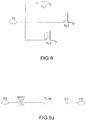
- the figure 8 represents such an adaptive network.
- This adaptive network RA making it possible to guarantee optimal operation of the dual-mode mixer must therefore adapt the impedances according to the frequencies involved. That is to say, this network must bring a short-circuit to the frequency RF, to the frequency Receiving OL and at the IF frequency and an open circuit at the transmission OL frequency.
- the RF filtering network ( figure 9a ) should ideally have good RF frequency matching at the diodes and an open circuit at FI, FOL-R and FOL-T.
- OL filtering network ( figure 9b ) must present at the level of the diodes a good adaptation to the frequencies OL: FOL-R and FOL-T and an open circuit at the frequencies FI and RF.
- the FI filtering network ( Figure 9c ), must have at the level of the diodes a good adaptation to the frequency IF and an open circuit at the frequencies RF and OL of emission and reception.
- the Figure 9c shows that the filtering network FI is a simple low-pass filter LC of order 2, L1, C3 between the ports P6 and P7.
- L1 44nH
- C3 3pF.
- the conversion losses are relatively low, approximately 7-8 dB, that the losses are approximately constant from one mode to another and that the power levels of the local oscillator OL make it possible to achieve losses.
- conversion rates are relatively low, between 1 and 3dBm.
Abstract
Description
L'invention concerne un mélangeur de signaux à différentes fréquences pour une tête d'émission/réception (en anglais : front-end) d'un système semi-duplex (en anglais : half duplex) rétrodirectif comportant un réseau d'antennes.The invention relates to a signal mixer at different frequencies for a transmission / reception head (in English: front-end) of a retrodirective half-duplex system (in English: half duplex) comprising an antenna array.
Cette invention s'inscrit dans le cadre d'un projet concernant les transmissions sans fils en technologie GWT (Gigabit-Wireless-Technology) dans les systèmes de radiocommunication.This invention is part of a project on wireless transmissions in GWT (Gigabit-Wireless-Technology) technology in radio communication systems.
Les systèmes rétrodirectifs, sont capables, après avoir reçu un signal d'une direction donnée sur un réseau d'antennes, de transmettre de manière automatique une réponse dans la même direction, sans connaissance a priori de l'angle d'arrivée de ce signal. Un système semi-duplex est capable de transmettre des informations sur un canal bidirectionnel dans un seul sens à la fois.The retrodirective systems are capable, after having received a signal of a given direction on an antenna array, to automatically transmit a response in the same direction, without prior knowledge of the arrival angle of this signal. . A half-duplex system is capable of transmitting information over a bidirectional channel in one direction at a time.
Des systèmes d'antennes rétrodirectifs pour les communications sans fils sont connus du document
D'autres réseaux utilisent des mélangeurs hétérodynes, tel le réseau représenté par la
Assurant la fonction de transposition de fréquence, le mélangeur est un composant essentiel de ces réseaux d'émetteurs et récepteurs.Assuring the transposition function of frequency, the mixer is an essential component of these networks of transmitters and receivers.
Du document "
Le principe de fonctionnement d'un tel circuit, en référence avec la
En mode réception Rx de ce circuit, le signal entrant de fréquence F-RF, par exemple 5,24GHz, reçu par un des d'éléments rayonnants R1, est amplifié par un amplificateur A1 et appliqué à l'entrée Σ d'un coupleur hybride (Rat-race coupler). Les signaux S1 et S2 de sortie du coupleur sont filtrés puis appliqués à la voie RF des mélangeurs M1, M2 et mélangés soit directement, soit avec une ligne de retard L avec un signal en provenance d'un oscillateur local OL de fréquence FOL-R approximativement égale à la moitié de celle F-RF du signal entrant, soit par exemple 2,625 GHz. Les mélangeurs fonctionnent ici dans un mode dit subharmonique, le produit du mélange des fréquences FOL-R et F-RF donne ainsi une fréquence intermédiaire FI proche de zéro, soit en bande de base et les signaux sont émis sur les voies I/Q en bande de base à cette fréquence. Le retard ajouté par la ligne de retard est de 45° à la fréquence de réception FOL-R. De ce fait, les mélangeurs étant en mode subharmonique, les signaux en fréquence FI en sortie des mélangeurs sont en quadrature de phase et permettent ainsi d'appliquer les schémas de démodulations classiques associées.In reception mode Rx of this circuit, the incoming signal of frequency F-RF, for example 5.24 GHz, received by one of the radiating elements R1, is amplified by an amplifier A1 and applied to the input Σ of a coupler hybrid (rat-race coupler). The output signals S1 and S2 of the coupler are filtered and then applied to the RF channel of the mixers M1, M2 and mixed either directly or with a delay line L with a signal coming from a local oscillator OL of frequency FOL-R approximately equal to half of that F-RF of the incoming signal, for example 2.625 GHz. The mixers operate here in a so-called subharmonic mode, the product of the mixture of frequencies FOL-R and F-RF thus gives an IF intermediate frequency close to zero, either in baseband and the signals are emitted on the I / Q channels in baseband at this frequency. The delay added by the delay line is 45 ° at the reception frequency FOL-R. As a result, since the mixers are in subharmonic mode, the IF frequency signals at the output of the mixers are in phase quadrature and thus make it possible to apply the associated conventional demodulation schemes.
En mode transmission de ce circuit, il faut assurer la rétrodirectivité. Pour ce faire et comme expliqué précédemment et décrit en
Quant aux dispositifs de filtrage associés aux mélangeurs, ils permettent d'isoler les signaux les uns des autres afin d'assurer un fonctionnement optimal. Ainsi, les filtres passe-bande BPF1, BPF2 sur la voie RF laissent passer la bande utile et rejettent la fréquence F-FI et les 2 fréquences de l'oscillateur FOL-R et FOL-T. Les filtres passe-bas LPF3, LPF4 sur les voies I/Q ont une fréquence de coupure en bande de base, rejetant ainsi la bande RF et les 2 fréquences FOL-R et FOL-T.As for the filtering devices associated with the mixers, they make it possible to isolate the signals from each other in order to ensure optimum operation. Thus, the bandpass filters BPF1, BPF2 on the RF channel pass the useful band and reject the frequency F-FI and the 2 frequencies of the oscillator FOL-R and FOL-T. The LPF3, LPF4 low-pass filters on the I / Q channels have a baseband cutoff frequency, thus rejecting the RF band and the 2 FOL-R and FOL-T frequencies.
Et les filtres F5 et F6 sur les voies OL des signaux de l'oscillateur local OL, sont une combinaison de filtre passe-haut, pour rejeter la fréquence F-FI, et de filtre réjecteur, pour rejeter la fréquence F-RF.And the filters F5 and F6 on the OL channels of the signals of the local oscillator OL, are a combination of high-pass filter, to reject the frequency F-FI, and of the rejection filter, to reject the frequency F-RF.
Ainsi, l'architecture décrite précédemment implique l'utilisation d'un mélangeur fonctionnant suivant 2 modes : mode harmonique simple en émission et mode subharmonique en réception.Thus, the architecture described above involves the use of a mixer operating in 2 modes: simple harmonic mode in transmission and subharmonic mode in reception.
Les mélangeurs décrits ci-dessus comprennent un simple transistor FET en technologie AsGa.The mixers described above comprise a single FET transistor in AsGa technology.
Or les performances intrinsèques de ces mélangeurs sont faibles. En termes de pertes de conversion par exemple, elles sont de l'ordre de 13dB en tenant compte d'un gain de conversion en réception de 7dB et d'un gain d'amplificateur de 20dB. Ces pertes de conversion élevées qui doivent être compensées par le gain des amplificateurs, ont donc un impact important sur le bilan énergétique du système rétrodirectif. Un prototype montre une consommation en puissance de 160mW par voie d'émission/réception TX/RX, soit 640mW pour un réseau à 4 circuits, circuit 1 - circuit 4 tel représenté par la
Une autre structure de mélangeur utilisable consiste à utiliser des paires de diodes dans une configuration antiparallèles et est proposée dans le document « balanced subharmonic mixers for retrodirective array application» de Thorsten Brabetz ou dans le document
De même, le document intitulé « méthode de conception des mélangeurs millimétriques » de Peter Butterworth - Université de Limoges, décrit également une réalisation de mélangeurs sous-harmoniques à partir d'une paire de diodes antiparallèles en mode réception. La
Bien que ce document propose un mélangeur en mode émission et un mélangeur en mode réception, il ne propose pas de mélangeurs bi-mode car la séparation des fréquences ne peut être réalisée simplement.Although this document proposes a mixer in transmission mode and a mixer in reception mode, it does not propose dual-mode mixers because the separation of the frequencies can not be carried out simply.
L'invention propose donc un mélangeur bi-mode avec de bonnes performances. L'invention consiste en un mélangeur de signaux à différentes fréquences selon la revendication 1 . . Dans un mode de réalisation le réseau adaptatif comprend un réseau d'impédances telles que, à la fréquence du signal de réception F-RF, à la fréquence du signal de l'oscillateur local OL de réception F-OLR et à la fréquence d'émission du signal intermédiaire F-FI corresponde un état de court circuit et à la fréquence de l'oscillateur local OL d'émission F-OLT, corresponde un état de circuit ouvert. Selon une variante de l'invention, le réseau d'impédances comprend une première ligne TL1 demi quart d'onde à la fréquence d'émission F-RF en court circuit, une seconde ligne quart d'onde TL2 et une troisième ligne demi-onde TL3 à cette fréquence d'émission F-RF en circuit ouvert , ces première, seconde et troisième lignes ont chacune une impédance caractéristique d'une valeur de 50ohms et sont jointes au port commun. Dans un mode de réalisation, le réseau de filtrage pour l'isolation entre les différentes voies du mélangeur comprend un filtre RF, relié au port de la voie RF, présentant un circuit ouvert à la fréquence d'émission du signal intermédiaire F-FI ainsi qu'aux fréquences F-OLR et F-OLT de l'oscillateur local, un filtre OL, relié au port de la voie OL, présentant un circuit ouvert aux fréquences d'émission/réception F-FI et F-RF et un filtre FI, relié au port de la voie FI et présentant un circuit ouvert à la fréquence de réception F-RF et aux fréquences F-OLR et F-OLT de l'oscillateur local, et les différents filtres sont adaptés à leur fréquence nominale de fonctionnement.The invention therefore proposes a dual-mode mixer with good performance. The invention consists of a signal mixer at different frequencies according to
Le mélangeur selon l'invention a des pertes de conversion faibles, et quasiment identiques quelque soit le mode de fonctionnement. Le concept simplement basé sur l'utilisation de diodes Schottky est à bas coût et le réseau d'adaptation auto-configurable de manière passive pour la sélection du mode de fonctionnement permet une consommation de puissance associée faible.The mixer according to the invention has low conversion losses, and almost identical whatever the mode of operation. The concept simply based on the use of Schottky diodes is low cost and the passively self-configuring adaptation network for the selection of the operating mode allows a low associated power consumption.
Les caractéristiques et avantages de l'invention mentionnée ci-dessus, ainsi que d'autres, apparaîtront plus clairement à la lecture de la description suivante, faite en relation avec les dessins joints, dans lesquels :
- La
figure 1 déjà décrite, représente un réseau rétrodirectif passif selon un état de la technique ; - La
figure 2 déjà décrite, représente un réseau rétrodirectif hétérodyne selon un état de la technique ; - La
figure 3 déjà décrite, représente l'architecture d'un circuit frontal émission/réception d'un système rétrodirectif semi-duplex selon un état de la technique ;
- La
figure 4 déjà décrite, représente un système rétrodirectif semi-duplex à 4 circuits selon un état de la technique ; - Les
figures 5a et 5b déjà décrites, représentent des réseaux de diodes pour les mélangeurs du système rétrodirectif de lafigure 4 connus d'un état de la technique ; -lafigure 6 représente un schéma de réseau à diodes comprenant un réseau adaptatif pour le mélangeur bi-mode selon l'invention ; - La
figure 7 représente un schéma du mélangeur bi-mode selon l'invention ; - La
figure 8 représente un réseau adaptatif du mélangeur selon l'invention ; - Et les
figures 9a ,9b et 9c représentent respectivement des réseaux de filtrage RF, OL et FI d'un mélangeur bi-mode selon l'invention. Pour simplifier la description, les mêmes références seront utilisées dans ces dernières figures pour désigner les éléments remplissant des fonctions identiques.
- The
figure 1 already described, represents a passive retrodirective network according to a state of the art; - The
figure 2 already described, represents a heterodyne retrodirective network according to a state of the art; - The
figure 3 already described, represents the architecture of a front-end transmission / reception circuit of a semi-duplex retrodirective system according to a state of the technical;
- The
figure 4 already described, represents a semi-duplex retrodirective system with 4 circuits according to a state of the art; - The
Figures 5a and 5b already described, represent diode arrays for the mixers of the retrodirective system of thefigure 4 known from a state of the art; -thefigure 6 represents a diode array diagram comprising an adaptive network for the dual-mode mixer according to the invention; - The
figure 7 represents a diagram of the dual-mode mixer according to the invention; - The
figure 8 represents an adaptive network of the mixer according to the invention; - And the
Figures 9a ,9b and 9c represent, respectively, RF, OL and FI filtering networks of a two-mode mixer according to the invention. To simplify the description, the same references will be used in these last figures to designate elements fulfilling identical functions.
L'invention concerne donc un mélangeur bi-mode tel représenté par la
L'une des diodes D1 est mise à la masse à travers un réseau adaptatif passif RA apte à s'auto-configurer selon l'un des modes de fonctionnement choisi, l'émission ou la réception. L'autre diode D2 est directement reliée à la masse par sa cathode. Ce circuit permet par ailleurs des conditions de charge spécifiques pour un fonctionnement bi-modal.One of the diodes D1 is grounded through a passive adaptive network RA able to self-configure according to one of the selected modes of operation, transmission or reception. The other diode D2 is directly connected to the ground by its cathode. This circuit also allows specific load conditions for bi-modal operation.
A ce circuit adaptatif de modes et afin d'assurer une bonne isolation entre les différents accès RF, OL et FI du mélangeur reliés aux voies RF, OL et FI pour l'émission ou la réception des signaux RF, OL et FI, des réseaux de filtrage RF, OL et FI présentent des charges appropriées au point d'accès B aux diodes, selon les fréquences en jeu.To this adaptive mode circuit and in order to ensure a good isolation between the various RF, OL and FI accesses of the mixer connected to the RF, OL and FI channels for the transmission or reception of the RF, OL and FI signals, networks RF filtering, OL and FI present appropriate charges to the access point B to the diodes, depending on the frequencies involved.
Les diodes Schottky sont couramment utilisées pour concevoir de tels mélangeurs. En effet, elles ont un coût très faible et elles permettent d'atteindre des pertes de conversion relativement faibles (6-8dB) avec des puissances d'oscillateur local OL assez faibles aussi (2-7dBm). L'idée de l'invention est donc de concevoir un mélangeur bi-mode tel représenté par la
Ce réseau adaptatif RA permettant de garantir un fonctionnement optimal du mélangeur bi-mode doit donc adapter les impédances selon les fréquences en jeu. C'est-à-dire que ce réseau doit ramener un court-circuit à la fréquence RF, à la fréquence OL de réception et à la fréquence FI ainsi qu'un circuit ouvert à la fréquence OL d'émission.This adaptive network RA making it possible to guarantee optimal operation of the dual-mode mixer must therefore adapt the impedances according to the frequencies involved. That is to say, this network must bring a short-circuit to the frequency RF, to the frequency Receiving OL and at the IF frequency and an open circuit at the transmission OL frequency.
Dans la bande WIFI des fréquences de 5GHz, par exemple, avec :
- Une fréquence de réception de F-RX=5.24GHz
- Une fréquence intermédiaire de F-FI=10MHz
- Soit une fréquence d'oscillateur local OL en réception de FOL-30 R=2.625GHz
- Une fréquence d'émission de F-TX=5.26GHz
- Soit, une fréquence d'oscillateur local OL en émission de FOLT=10.5GHz.
- A reception frequency of F-RX = 5.24GHz
- An intermediate frequency of F-FI = 10MHz
- Let a local oscillator frequency OL receive FOL-30 R = 2.625GHz
- An emission frequency of F-TX = 5.26GHz
- That is, a local oscillator frequency OL in FOLT transmission = 10.5GHz.
Un réseau adaptatif RA permettant de garantir un fonctionnement optimal du mélangeur bi-mode doit donc ramener les impédances suivantes selon les fréquences en jeu :
- court-circuit aux fréquences RF autour de 5.25GHz ;
- court-circuit à la fréquence OL de réception de 2.625GHz ;
- circuit ouvert à la fréquence OL d'émission de 10.5GHz ;
- court-circuit à la fréquence FI de 10MHz.
- short circuit at RF frequencies around 5.25GHz;
- short circuit at reception frequency of 2.625GHz OL;
- open circuit at OL emission frequency of 10.5GHz;
- short circuit at the IF frequency of 10MHz.
Et conformément à la
Une 1ère ligne TL1 en court-circuit, de longueur électrique égale à λ/8 (λétant la longueur d'onde) à la fréquence RF de 5.25GHz ;Une 2ème ligne TL2 en circuit ouvert, de longueur λ/4 à la même fréquence ;Une 3ème ligne TL3 en circuit ouvert, de longueur λ/2 à la même fréquence.
- A 1 st line TL1 shorted to electrical length equal to λ / 8 (λétant wavelength) at the RF frequency of 5.25 GHz;
- A 2nd line TL2 open circuit, length λ / 4 at the same frequency;
- A 3 rd line TL3 in open circuit, of length λ / 2 at the same frequency.
Ce réseau est capable de remplir les conditions de charge selon les modes de fonctionnement et définies précédemment:
- Le court-circuit au point A à 5.25GHz est obtenu grâce à la ligne TL2. En effet, il est connu de l'homme du métier qu'une ligne quart d'onde est un inverseur d'impédance, ici le circuit ouvert en bout de la ligne TL2 ramène donc un court-circuit à son entrée.
- Le court-circuit à 2.625GHz est obtenu grâce à la ligne TL3. En effet, cette ligne a une longueur électrique égale au quart d'onde à cette fréquence de 2.625GHz qui est la fréquence moitié de 5.25GHz et le circuit ouvert à son extrémité ramène donc bien aussi un circuit ouvert à son entrée.
- Le circuit ouvert à 10.5GHz est assuré par les 3 lignes :
- TL1 est une ligne quart d'onde à cette fréquence (fréquence double de 5.25GHz), le CC à son extrémité est donc transformé en circuit ouvert à son entrée.
- TL2 est une ligne demi-onde à la même fréquence, le circuit 30 ouvert à son extrémité est alors ramené à son entrée.
- TL3 à 10.5GHz a une longueur égale à la longueur d'onde, le circuit ouvert à son extrémité est aussi ramené à son entrée.
- Le court-circuit à 10MHz est assuré sans problème par la ligne TL1 qui est mise à la masse et dont la longueur physique est négligeable par rapport à 35 la longueur d'onde à 10MHz.
- The short-circuit at point A at 5.25GHz is obtained thanks to the TL2 line. Indeed, it is known to those skilled in the art that a quarter-wave line is an impedance inverter, here the open circuit at the end of the line TL2 thus brings a short circuit to its input.
- The short circuit at 2.625GHz is obtained thanks to the TL3 line. Indeed, this line has an electric length equal to quarter wave at this frequency of 2.625GHz which is the frequency half of 5.25GHz and the open circuit at its end therefore also brings an open circuit at its input.
- The open circuit at 10.5GHz is provided by the 3 lines:
- TL1 is a quarter-wave line at this frequency (double frequency of 5.25GHz), the DC at its end is converted into an open circuit at its input.
- TL2 is a half-wave line at the same frequency, the circuit 30 open at its end is then returned to its input.
- TL3 at 10.5GHz has a length equal to the wavelength, the open circuit at its end is also brought back to its input.
- The short circuit at 10MHz is assured without problem by the TL1 line which is grounded and whose physical length is negligible compared to the wavelength at 10MHz.
Des exemples de réseaux de filtrage RF, OL et FI, sont représentés par les
Le réseau de filtrage RF (
Le réseau de filtrage RF représenté par la
- un filtre passe-bande BPF1 idéal d'ordre 4, centré autour de 5.25GHz, ayant pour rôle d'isoler la bande RF de celles de la FI, FOL-R et FOL-T ;
- une ligne de transmission idéale TL10 ayant pour rôle de déphaser le signal afin de présenter le circuit ouvert requis aux accès du filtre aux fréquences FO-LR et FOL-T. Il est à noter que la longueur de cette ligne sera à ajuster lors de la simulation complète du mélangeur afin d'en optimiser les performances ;
- et une capacité série C1 ayant pour rôle de présenter le circuit ouvert requis au point d'accès aux diodes à la fréquence FI. Les valeurs suivantes des différents composants de ce réseau de filtrage sont proposées à titre d'exemple :
- Filtre BPF1 : filtre Chebyshev, N=4, centré sur 5.25GHz, band passante 1.5GHz
- TL10 : Z=500hm,E=148° (phase à ajuster) F=5.25GHz
- C1=5pF.
- an ideal BPF1 band-pass filter of
order 4, centered around 5.25GHz, whose function is to isolate the RF band from those of IF, FOL-R and FOL-T; - an ideal TL10 transmission line whose function is to phase out the signal in order to present the required open circuit to the filter accesses at frequencies FO-LR and FOL-T. It should be noted that the length of this line will be adjusted during the complete simulation of the mixer to optimize performance;
- and a C1 series capacitor having the role of presenting the required open circuit at the point of access to the diodes at the IF frequency. The following values of the different components of this filter network are proposed as an example:
- BPF1 filter: Chebyshev filter, N = 4, centered on 5.25GHz, bandwidth 1.5GHz
- TL10: Z = 500hm, E = 148 ° (phase to be adjusted) F = 5.25GHz
- C1 = 5pF.
Le réseau de filtrage OL, apte à répondre aux exigences précitées est 30 représenté par la
- une ligne TL12 quart-d'onde à la fréquence RF (5.25GHz) en circuit ouvert, qui ramène donc un court-circuit à son entrée, coupant ainsi le signal RF entre les ports P4 et P5 ;
- une ligne série TL11 quart d'onde à la fréquence RF, permettant de ramener à partir du précédent court-circuit un circuit ouvert au port P4 tel que requis ;
- une capacité série C2 permettant d'avoir aussi un circuit ouvert à la fréquence FI, vu du port P4 du filtre ;Les valeurs suivantes des différents composants de ce réseau de filtrage sont proposées à titre d'exemple :
- TL12: Z=100 Ohm,E=90° F=5.25GHz
- TL11: Z=50 Ohm,E=90° F=5.25GHz
- C2=5pF.
- a line TL12 quarter-wave at RF frequency (5.25GHz) in open circuit, which thus brings a short circuit to its input, thus cutting the RF signal between the ports P4 and P5;
- a quarter-wave TL11 line at the RF frequency, making it possible to bring back from the previous short-circuit an open circuit to the port P4 as required;
- a C2 series capacitance allowing to have also an open circuit at the frequency FI, seen from the port P4 of the filter; the following values of the different components of this filter network are proposed as an example:
- TL12: Z = 100 Ohm, E = 90 ° F = 5.25GHz
- TL11: Z = 50 Ohm, E = 90 ° F = 5.25GHz
- C2 = 5pF.
La
Au point de liaison B des diodes antiparallèles, sont connectés les différents ports P3, P4, P6 des réseaux de filtrage tel que décrit précédemment par les
On peut remarquer que les pertes de conversion sont relativement faibles, soit environ 7-8dB, que les pertes sont approximativement constantes d'un mode à l'autre et que les niveaux de puissance de l'oscillateur local OL permettant d'atteindre des pertes de conversion minimales sont relativement faibles, entre 1 et 3dBm.It can be noted that the conversion losses are relatively low, approximately 7-8 dB, that the losses are approximately constant from one mode to another and that the power levels of the local oscillator OL make it possible to achieve losses. conversion rates are relatively low, between 1 and 3dBm.
Claims (4)
- Signal mixer at different frequencies corresponding to a sending mode and a receiving mode comprising:a diode array comprising a pair of diodes connected in anti-parallel, a first connection point (C) of the diodes being connected to the earth, the second connection point (B) being connected to the sending/receiving signal channel ports and to the channel port of a local oscillator (OL) at different frequencies,and a filtering network connected between the second connection point (B) and each of the ports of the sending/receiving channels and of the local oscillator channel.characterized in thatan adaptive array (RA), for dual-mode use in sending mode and in receiving mode, is connected in series in the diode array between the first connection point (C) connected to the earth and the anode of one of the diodes of the diode array, the adaptive array comprising means to make a first open circuit state in sending mode and a second short circuit state in receiving mode.
- Mixer according to claim 1 characterized in that said means comprise an impedance network such that, to the frequency of the reception signal, to the frequency of the signal of the local receiving oscillator, to the sending frequency of the intermediate signal corresponds a short circuit state and to the frequency of the local sending oscillator corresponds an open circuit state.
- Mixer according to claim 2 characterized in that the impedance network comprises a first half quarter wave line (TL1) at the sending frequency in short circuit, a second quarter wave line (TL2) and a third half wave line (TL3) at this sending frequency in open circuit, these first, second and third lines each have a characteristic impedance of a value of 50 ohms and are joined at the common port.
- Mixer according to claim 1 characterized in that the filtering network for isolation between the various mixer channels comprises: a radio-frequency filter connected to the port of the radio-frequency channel, presenting an open circuit at the sending frequency of the intermediate signal of the local oscillator as well as at the frequencies of the local receiving and sending oscillator, a local oscillator filter connected to the port of the local oscillator channel presenting an open circuit at the sending/receiving frequencies, and an intermediate frequency filter connected to the port of the intermediate frequency channel and presenting an open circuit at the receiving frequency and at the frequencies of the local receiving and sending oscillator, and in that said filters are adapted at their nominal operating frequency.
Applications Claiming Priority (2)
| Application Number | Priority Date | Filing Date | Title |
|---|---|---|---|
| FR0856080A FR2935849A1 (en) | 2008-09-10 | 2008-09-10 | MIXER BI-MODE SIGNALS |
| PCT/EP2009/061357 WO2010028998A1 (en) | 2008-09-10 | 2009-09-02 | Dual-mode mixer |
Publications (2)
| Publication Number | Publication Date |
|---|---|
| EP2335349A1 EP2335349A1 (en) | 2011-06-22 |
| EP2335349B1 true EP2335349B1 (en) | 2012-05-09 |
Family
ID=40568677
Family Applications (1)
| Application Number | Title | Priority Date | Filing Date |
|---|---|---|---|
| EP09782522A Not-in-force EP2335349B1 (en) | 2008-09-10 | 2009-09-02 | Dual-mode mixer |
Country Status (8)
| Country | Link |
|---|---|
| US (1) | US8767594B2 (en) |
| EP (1) | EP2335349B1 (en) |
| JP (1) | JP5702722B2 (en) |
| KR (1) | KR20110067095A (en) |
| CN (1) | CN102210095B (en) |
| AT (1) | ATE557470T1 (en) |
| FR (1) | FR2935849A1 (en) |
| WO (1) | WO2010028998A1 (en) |
Families Citing this family (7)
| Publication number | Priority date | Publication date | Assignee | Title |
|---|---|---|---|---|
| DE102010041372A1 (en) * | 2010-09-24 | 2012-03-29 | Siemens Aktiengesellschaft | Method and device for processing signals |
| US10145729B2 (en) * | 2012-05-22 | 2018-12-04 | Teknologian Tutkimuskeskus Vtt Oy | Intermodulation sensor platform based on mechanical resonator |
| DK3205016T3 (en) * | 2014-10-06 | 2021-01-11 | Ericsson Telefon Ab L M | Amplifier circuit and procedure |
| JP2016086417A (en) * | 2014-10-27 | 2016-05-19 | 島田理化工業株式会社 | Frequency mixer, frequency converter, signal quality measurement system, and transmitter |
| CN106374871B (en) * | 2016-10-20 | 2019-08-27 | 南京熊猫电子股份有限公司 | A kind of active band-pass filter applied to long-wave time service frequency range |
| US10840596B2 (en) * | 2018-05-22 | 2020-11-17 | Plume Design, Inc. | Tunable antenna system for Bluetooth and Wi-Fi bands with electronically-reconfigurable and mechanically-identical antennas |
| KR102337322B1 (en) * | 2019-08-14 | 2021-12-09 | 주식회사 엠티오메가 | Harmonic Dual band APD(Anti-Parallel Diodes) frequency Mixer |
Family Cites Families (7)
| Publication number | Priority date | Publication date | Assignee | Title |
|---|---|---|---|---|
| US4340975A (en) * | 1979-10-09 | 1982-07-20 | Matsushita Electric Industrial Company, Limited | Microwave mixing circuit and a VHF-UHF tuner having the mixing circuit |
| US4749949A (en) * | 1986-04-29 | 1988-06-07 | Hewlett-Packard Company | Self biasing diode microwave frequency multiplier |
| CN1151229A (en) * | 1994-05-19 | 1997-06-04 | 奥泰尔公司 | In-line predistorted for linearization of electronic and optical signals |
| IT1294732B1 (en) * | 1997-09-15 | 1999-04-12 | Italtel Spa | IMAGE REJECTION SUBHARMONIC FREQUENCY CONVERTER MADE IN MICRO-STRIP, PARTICULARLY SUITABLE FOR USE IN |
| JP3453326B2 (en) * | 1999-06-23 | 2003-10-06 | 三菱電機株式会社 | Mixer for frequency conversion |
| JP4412458B2 (en) * | 2002-10-22 | 2010-02-10 | 日本電気株式会社 | Mixer circuit |
| JP4152985B2 (en) * | 2003-10-30 | 2008-09-17 | 三菱電機株式会社 | Pulse modulation circuit |
-
2008
- 2008-09-10 FR FR0856080A patent/FR2935849A1/en not_active Withdrawn
-
2009
- 2009-09-02 AT AT09782522T patent/ATE557470T1/en active
- 2009-09-02 EP EP09782522A patent/EP2335349B1/en not_active Not-in-force
- 2009-09-02 CN CN200980144590.2A patent/CN102210095B/en not_active Expired - Fee Related
- 2009-09-02 US US12/998,012 patent/US8767594B2/en not_active Expired - Fee Related
- 2009-09-02 WO PCT/EP2009/061357 patent/WO2010028998A1/en active Application Filing
- 2009-09-02 KR KR1020117005569A patent/KR20110067095A/en active IP Right Grant
- 2009-09-02 JP JP2011525540A patent/JP5702722B2/en not_active Expired - Fee Related
Also Published As
| Publication number | Publication date |
|---|---|
| FR2935849A1 (en) | 2010-03-12 |
| CN102210095B (en) | 2015-02-18 |
| CN102210095A (en) | 2011-10-05 |
| KR20110067095A (en) | 2011-06-21 |
| EP2335349A1 (en) | 2011-06-22 |
| WO2010028998A1 (en) | 2010-03-18 |
| US20110158136A1 (en) | 2011-06-30 |
| JP5702722B2 (en) | 2015-04-15 |
| US8767594B2 (en) | 2014-07-01 |
| ATE557470T1 (en) | 2012-05-15 |
| JP2012507176A (en) | 2012-03-22 |
Similar Documents
| Publication | Publication Date | Title |
|---|---|---|
| EP2335349B1 (en) | Dual-mode mixer | |
| EP1097509B1 (en) | Vectorial modulator | |
| EP1427053B1 (en) | Directional coupler | |
| FR2984603A1 (en) | INTEGRATED CIRCUIT COMPRISING AN INTEGRATED TRANSFORMER OF THE "BALUN" TYPE WITH SEVERAL INPUT AND OUTPUT PATHS. | |
| EP2483965B1 (en) | Selectivity enhancement for a dual-band coupler | |
| EP1172929B1 (en) | Low noise amplifier arrangement especially for cellular mobile telephone | |
| EP2243268B1 (en) | Radiofrequency emission system | |
| EP0773654A1 (en) | Direct demodulation stage for a quadrature modulated signal, and receiver with such a demodulation stage | |
| EP2204877A1 (en) | Trim of a balun | |
| EP3188399A1 (en) | Ibfd transceiver module with non-reciprocal frequency transposition | |
| FR3049758A1 (en) | POWER TRANSFORMER OF SYMMETRIC-DISSYMETRIC TYPE WITH COMPLETELY BALANCED TOPOLOGY | |
| EP0795954B1 (en) | Apparatus comprising a ring mixer | |
| WO2015000984A1 (en) | Band rejection filter | |
| FR2902250A1 (en) | SWITCH AND SELECTIVE ISOLATION SWITCHING DEVICE FOR MULTIMEDIA TERMINALS | |
| EP0472483A1 (en) | Bidirectional duplexer for polarised microwaves, particularly realised in monolithic technology on gallium arsenide | |
| EP1148631A1 (en) | Frequency translator with image frequency signal suppression | |
| EP0083895B1 (en) | Microwave circuit acting as modulator, mixer and transmission-reception separator and devices using such a circuit | |
| EP1801968B1 (en) | Broadband balun structure | |
| EP3714559A1 (en) | Method and device for calibrating the centre frequency of a hybrid coupler | |
| EP3941009A1 (en) | Device and method for receiving and demodulating an amplitude-modulated rf signal | |
| EP1251634A1 (en) | Transconductance stage and RF communications device including such a stage | |
| FR3115429A1 (en) | Module for transmitting/receiving signals, in particular radio frequency signals, and corresponding communication device | |
| US7835705B2 (en) | Integrated bidirectional junction engineered dual insulator transceiver | |
| EP0943176A1 (en) | Double balanced compact mixer using microwave monolithic integrated circuit cold fet quad | |
| EP1715597B1 (en) | Antenna composed of planar surfaces connected by switching circuits |
Legal Events
| Date | Code | Title | Description |
|---|---|---|---|
| PUAI | Public reference made under article 153(3) epc to a published international application that has entered the european phase |
Free format text: ORIGINAL CODE: 0009012 |
|
| 17P | Request for examination filed |
Effective date: 20110309 |
|
| AK | Designated contracting states |
Kind code of ref document: A1 Designated state(s): AT BE BG CH CY CZ DE DK EE ES FI FR GB GR HR HU IE IS IT LI LT LU LV MC MK MT NL NO PL PT RO SE SI SK SM TR |
|
| AX | Request for extension of the european patent |
Extension state: AL BA RS |
|
| RIN1 | Information on inventor provided before grant (corrected) |
Inventor name: COUPEZ, JEAN-PHILIPPE Inventor name: LO HINE TONG, DOMINIQUE Inventor name: LE PENNEC, FRANCOIS |
|
| DAX | Request for extension of the european patent (deleted) | ||
| GRAP | Despatch of communication of intention to grant a patent |
Free format text: ORIGINAL CODE: EPIDOSNIGR1 |
|
| RIN1 | Information on inventor provided before grant (corrected) |
Inventor name: LO HINE TONG, DOMINIQUE Inventor name: COUPEZ, JEAN-PHILIPPE Inventor name: LE PENNEC, FRANCOIS |
|
| GRAS | Grant fee paid |
Free format text: ORIGINAL CODE: EPIDOSNIGR3 |
|
| GRAA | (expected) grant |
Free format text: ORIGINAL CODE: 0009210 |
|
| AK | Designated contracting states |
Kind code of ref document: B1 Designated state(s): AT BE BG CH CY CZ DE DK EE ES FI FR GB GR HR HU IE IS IT LI LT LU LV MC MK MT NL NO PL PT RO SE SI SK SM TR |
|
| REG | Reference to a national code |
Ref country code: GB Ref legal event code: FG4D Free format text: NOT ENGLISH |
|
| REG | Reference to a national code |
Ref country code: AT Ref legal event code: REF Ref document number: 557470 Country of ref document: AT Kind code of ref document: T Effective date: 20120515 Ref country code: CH Ref legal event code: EP |
|
| REG | Reference to a national code |
Ref country code: IE Ref legal event code: FG4D Free format text: LANGUAGE OF EP DOCUMENT: FRENCH |
|
| REG | Reference to a national code |
Ref country code: DE Ref legal event code: R096 Ref document number: 602009006833 Country of ref document: DE Effective date: 20120705 |
|
| REG | Reference to a national code |
Ref country code: NL Ref legal event code: VDEP Effective date: 20120509 |
|
| REG | Reference to a national code |
Ref country code: LT Ref legal event code: MG4D Effective date: 20120509 |
|
| PG25 | Lapsed in a contracting state [announced via postgrant information from national office to epo] |
Ref country code: CY Free format text: LAPSE BECAUSE OF FAILURE TO SUBMIT A TRANSLATION OF THE DESCRIPTION OR TO PAY THE FEE WITHIN THE PRESCRIBED TIME-LIMIT Effective date: 20120509 Ref country code: SE Free format text: LAPSE BECAUSE OF FAILURE TO SUBMIT A TRANSLATION OF THE DESCRIPTION OR TO PAY THE FEE WITHIN THE PRESCRIBED TIME-LIMIT Effective date: 20120509 Ref country code: IS Free format text: LAPSE BECAUSE OF FAILURE TO SUBMIT A TRANSLATION OF THE DESCRIPTION OR TO PAY THE FEE WITHIN THE PRESCRIBED TIME-LIMIT Effective date: 20120909 Ref country code: PL Free format text: LAPSE BECAUSE OF FAILURE TO SUBMIT A TRANSLATION OF THE DESCRIPTION OR TO PAY THE FEE WITHIN THE PRESCRIBED TIME-LIMIT Effective date: 20120509 Ref country code: NO Free format text: LAPSE BECAUSE OF FAILURE TO SUBMIT A TRANSLATION OF THE DESCRIPTION OR TO PAY THE FEE WITHIN THE PRESCRIBED TIME-LIMIT Effective date: 20120809 Ref country code: LT Free format text: LAPSE BECAUSE OF FAILURE TO SUBMIT A TRANSLATION OF THE DESCRIPTION OR TO PAY THE FEE WITHIN THE PRESCRIBED TIME-LIMIT Effective date: 20120509 Ref country code: FI Free format text: LAPSE BECAUSE OF FAILURE TO SUBMIT A TRANSLATION OF THE DESCRIPTION OR TO PAY THE FEE WITHIN THE PRESCRIBED TIME-LIMIT Effective date: 20120509 |
|
| REG | Reference to a national code |
Ref country code: AT Ref legal event code: MK05 Ref document number: 557470 Country of ref document: AT Kind code of ref document: T Effective date: 20120509 |
|
| PG25 | Lapsed in a contracting state [announced via postgrant information from national office to epo] |
Ref country code: GR Free format text: LAPSE BECAUSE OF FAILURE TO SUBMIT A TRANSLATION OF THE DESCRIPTION OR TO PAY THE FEE WITHIN THE PRESCRIBED TIME-LIMIT Effective date: 20120810 Ref country code: HR Free format text: LAPSE BECAUSE OF FAILURE TO SUBMIT A TRANSLATION OF THE DESCRIPTION OR TO PAY THE FEE WITHIN THE PRESCRIBED TIME-LIMIT Effective date: 20120509 Ref country code: PT Free format text: LAPSE BECAUSE OF FAILURE TO SUBMIT A TRANSLATION OF THE DESCRIPTION OR TO PAY THE FEE WITHIN THE PRESCRIBED TIME-LIMIT Effective date: 20120910 Ref country code: SI Free format text: LAPSE BECAUSE OF FAILURE TO SUBMIT A TRANSLATION OF THE DESCRIPTION OR TO PAY THE FEE WITHIN THE PRESCRIBED TIME-LIMIT Effective date: 20120509 Ref country code: LV Free format text: LAPSE BECAUSE OF FAILURE TO SUBMIT A TRANSLATION OF THE DESCRIPTION OR TO PAY THE FEE WITHIN THE PRESCRIBED TIME-LIMIT Effective date: 20120509 |
|
| PG25 | Lapsed in a contracting state [announced via postgrant information from national office to epo] |
Ref country code: DK Free format text: LAPSE BECAUSE OF FAILURE TO SUBMIT A TRANSLATION OF THE DESCRIPTION OR TO PAY THE FEE WITHIN THE PRESCRIBED TIME-LIMIT Effective date: 20120509 Ref country code: CZ Free format text: LAPSE BECAUSE OF FAILURE TO SUBMIT A TRANSLATION OF THE DESCRIPTION OR TO PAY THE FEE WITHIN THE PRESCRIBED TIME-LIMIT Effective date: 20120509 Ref country code: AT Free format text: LAPSE BECAUSE OF FAILURE TO SUBMIT A TRANSLATION OF THE DESCRIPTION OR TO PAY THE FEE WITHIN THE PRESCRIBED TIME-LIMIT Effective date: 20120509 Ref country code: SK Free format text: LAPSE BECAUSE OF FAILURE TO SUBMIT A TRANSLATION OF THE DESCRIPTION OR TO PAY THE FEE WITHIN THE PRESCRIBED TIME-LIMIT Effective date: 20120509 Ref country code: NL Free format text: LAPSE BECAUSE OF FAILURE TO SUBMIT A TRANSLATION OF THE DESCRIPTION OR TO PAY THE FEE WITHIN THE PRESCRIBED TIME-LIMIT Effective date: 20120509 Ref country code: EE Free format text: LAPSE BECAUSE OF FAILURE TO SUBMIT A TRANSLATION OF THE DESCRIPTION OR TO PAY THE FEE WITHIN THE PRESCRIBED TIME-LIMIT Effective date: 20120509 Ref country code: RO Free format text: LAPSE BECAUSE OF FAILURE TO SUBMIT A TRANSLATION OF THE DESCRIPTION OR TO PAY THE FEE WITHIN THE PRESCRIBED TIME-LIMIT Effective date: 20120509 |
|
| PG25 | Lapsed in a contracting state [announced via postgrant information from national office to epo] |
Ref country code: IT Free format text: LAPSE BECAUSE OF FAILURE TO SUBMIT A TRANSLATION OF THE DESCRIPTION OR TO PAY THE FEE WITHIN THE PRESCRIBED TIME-LIMIT Effective date: 20120509 |
|
| PLBE | No opposition filed within time limit |
Free format text: ORIGINAL CODE: 0009261 |
|
| STAA | Information on the status of an ep patent application or granted ep patent |
Free format text: STATUS: NO OPPOSITION FILED WITHIN TIME LIMIT |
|
| BERE | Be: lapsed |
Owner name: THOMSON LICENSING Effective date: 20120930 |
|
| 26N | No opposition filed |
Effective date: 20130212 |
|
| PG25 | Lapsed in a contracting state [announced via postgrant information from national office to epo] |
Ref country code: ES Free format text: LAPSE BECAUSE OF FAILURE TO SUBMIT A TRANSLATION OF THE DESCRIPTION OR TO PAY THE FEE WITHIN THE PRESCRIBED TIME-LIMIT Effective date: 20120820 Ref country code: MC Free format text: LAPSE BECAUSE OF NON-PAYMENT OF DUE FEES Effective date: 20120930 |
|
| REG | Reference to a national code |
Ref country code: DE Ref legal event code: R097 Ref document number: 602009006833 Country of ref document: DE Effective date: 20130212 |
|
| REG | Reference to a national code |
Ref country code: IE Ref legal event code: MM4A |
|
| PG25 | Lapsed in a contracting state [announced via postgrant information from national office to epo] |
Ref country code: BG Free format text: LAPSE BECAUSE OF FAILURE TO SUBMIT A TRANSLATION OF THE DESCRIPTION OR TO PAY THE FEE WITHIN THE PRESCRIBED TIME-LIMIT Effective date: 20120809 Ref country code: IE Free format text: LAPSE BECAUSE OF NON-PAYMENT OF DUE FEES Effective date: 20120902 Ref country code: BE Free format text: LAPSE BECAUSE OF NON-PAYMENT OF DUE FEES Effective date: 20120930 |
|
| PG25 | Lapsed in a contracting state [announced via postgrant information from national office to epo] |
Ref country code: MT Free format text: LAPSE BECAUSE OF FAILURE TO SUBMIT A TRANSLATION OF THE DESCRIPTION OR TO PAY THE FEE WITHIN THE PRESCRIBED TIME-LIMIT Effective date: 20120509 |
|
| PG25 | Lapsed in a contracting state [announced via postgrant information from national office to epo] |
Ref country code: TR Free format text: LAPSE BECAUSE OF FAILURE TO SUBMIT A TRANSLATION OF THE DESCRIPTION OR TO PAY THE FEE WITHIN THE PRESCRIBED TIME-LIMIT Effective date: 20120509 |
|
| REG | Reference to a national code |
Ref country code: CH Ref legal event code: PL |
|
| GBPC | Gb: european patent ceased through non-payment of renewal fee |
Effective date: 20130902 |
|
| PG25 | Lapsed in a contracting state [announced via postgrant information from national office to epo] |
Ref country code: SM Free format text: LAPSE BECAUSE OF FAILURE TO SUBMIT A TRANSLATION OF THE DESCRIPTION OR TO PAY THE FEE WITHIN THE PRESCRIBED TIME-LIMIT Effective date: 20120509 Ref country code: LU Free format text: LAPSE BECAUSE OF NON-PAYMENT OF DUE FEES Effective date: 20120902 |
|
| PG25 | Lapsed in a contracting state [announced via postgrant information from national office to epo] |
Ref country code: CH Free format text: LAPSE BECAUSE OF NON-PAYMENT OF DUE FEES Effective date: 20130930 Ref country code: GB Free format text: LAPSE BECAUSE OF NON-PAYMENT OF DUE FEES Effective date: 20130902 Ref country code: HU Free format text: LAPSE BECAUSE OF FAILURE TO SUBMIT A TRANSLATION OF THE DESCRIPTION OR TO PAY THE FEE WITHIN THE PRESCRIBED TIME-LIMIT Effective date: 20090902 Ref country code: LI Free format text: LAPSE BECAUSE OF NON-PAYMENT OF DUE FEES Effective date: 20130930 |
|
| PG25 | Lapsed in a contracting state [announced via postgrant information from national office to epo] |
Ref country code: MK Free format text: LAPSE BECAUSE OF FAILURE TO SUBMIT A TRANSLATION OF THE DESCRIPTION OR TO PAY THE FEE WITHIN THE PRESCRIBED TIME-LIMIT Effective date: 20120509 |
|
| REG | Reference to a national code |
Ref country code: FR Ref legal event code: PLFP Year of fee payment: 7 |
|
| PGFP | Annual fee paid to national office [announced via postgrant information from national office to epo] |
Ref country code: DE Payment date: 20150924 Year of fee payment: 7 |
|
| PGFP | Annual fee paid to national office [announced via postgrant information from national office to epo] |
Ref country code: FR Payment date: 20150917 Year of fee payment: 7 |
|
| REG | Reference to a national code |
Ref country code: DE Ref legal event code: R119 Ref document number: 602009006833 Country of ref document: DE |
|
| REG | Reference to a national code |
Ref country code: FR Ref legal event code: ST Effective date: 20170531 |
|
| PG25 | Lapsed in a contracting state [announced via postgrant information from national office to epo] |
Ref country code: DE Free format text: LAPSE BECAUSE OF NON-PAYMENT OF DUE FEES Effective date: 20170401 Ref country code: FR Free format text: LAPSE BECAUSE OF NON-PAYMENT OF DUE FEES Effective date: 20160930 |