EP2334400B1 - Filtervorrichtung für teichen und dergleichen - Google Patents
Filtervorrichtung für teichen und dergleichen Download PDFInfo
- Publication number
- EP2334400B1 EP2334400B1 EP09787024.0A EP09787024A EP2334400B1 EP 2334400 B1 EP2334400 B1 EP 2334400B1 EP 09787024 A EP09787024 A EP 09787024A EP 2334400 B1 EP2334400 B1 EP 2334400B1
- Authority
- EP
- European Patent Office
- Prior art keywords
- actuating means
- filtering
- filtering element
- filtering device
- supporting surface
- Prior art date
- Legal status (The legal status is an assumption and is not a legal conclusion. Google has not performed a legal analysis and makes no representation as to the accuracy of the status listed.)
- Not-in-force
Links
Images


Classifications
-
- A—HUMAN NECESSITIES
- A01—AGRICULTURE; FORESTRY; ANIMAL HUSBANDRY; HUNTING; TRAPPING; FISHING
- A01K—ANIMAL HUSBANDRY; AVICULTURE; APICULTURE; PISCICULTURE; FISHING; REARING OR BREEDING ANIMALS, NOT OTHERWISE PROVIDED FOR; NEW BREEDS OF ANIMALS
- A01K63/00—Receptacles for live fish, e.g. aquaria; Terraria
- A01K63/04—Arrangements for treating water specially adapted to receptacles for live fish
- A01K63/045—Filters for aquaria
-
- B—PERFORMING OPERATIONS; TRANSPORTING
- B01—PHYSICAL OR CHEMICAL PROCESSES OR APPARATUS IN GENERAL
- B01D—SEPARATION
- B01D29/00—Filters with filtering elements stationary during filtration, e.g. pressure or suction filters, not covered by groups B01D24/00 - B01D27/00; Filtering elements therefor
- B01D29/11—Filters with filtering elements stationary during filtration, e.g. pressure or suction filters, not covered by groups B01D24/00 - B01D27/00; Filtering elements therefor with bag, cage, hose, tube, sleeve or like filtering elements
- B01D29/114—Filters with filtering elements stationary during filtration, e.g. pressure or suction filters, not covered by groups B01D24/00 - B01D27/00; Filtering elements therefor with bag, cage, hose, tube, sleeve or like filtering elements arranged for inward flow filtration
-
- B—PERFORMING OPERATIONS; TRANSPORTING
- B01—PHYSICAL OR CHEMICAL PROCESSES OR APPARATUS IN GENERAL
- B01D—SEPARATION
- B01D29/00—Filters with filtering elements stationary during filtration, e.g. pressure or suction filters, not covered by groups B01D24/00 - B01D27/00; Filtering elements therefor
- B01D29/62—Regenerating the filter material in the filter
- B01D29/66—Regenerating the filter material in the filter by flushing, e.g. counter-current air-bumps
-
- B—PERFORMING OPERATIONS; TRANSPORTING
- B01—PHYSICAL OR CHEMICAL PROCESSES OR APPARATUS IN GENERAL
- B01D—SEPARATION
- B01D29/00—Filters with filtering elements stationary during filtration, e.g. pressure or suction filters, not covered by groups B01D24/00 - B01D27/00; Filtering elements therefor
- B01D29/62—Regenerating the filter material in the filter
- B01D29/70—Regenerating the filter material in the filter by forces created by movement of the filter element
-
- B—PERFORMING OPERATIONS; TRANSPORTING
- B01—PHYSICAL OR CHEMICAL PROCESSES OR APPARATUS IN GENERAL
- B01D—SEPARATION
- B01D29/00—Filters with filtering elements stationary during filtration, e.g. pressure or suction filters, not covered by groups B01D24/00 - B01D27/00; Filtering elements therefor
- B01D29/62—Regenerating the filter material in the filter
- B01D29/70—Regenerating the filter material in the filter by forces created by movement of the filter element
- B01D29/705—Regenerating the filter material in the filter by forces created by movement of the filter element by compression of compressible filter medium, e.g. foam
Definitions
- the present invention refers to a filtering device for ponds and the like.
- filtering devices that intake water from the pond, filter it by a filtering element placed therein, and deliver it back inside the pond. Nevertheless, it is evident that the filtering element will be quickly obstructed by impurities and dirt in the pond. Accordingly, such filtering devices have systems for providing a periodical cleaning of the filtering element, so as to remove the impurities and the dirt thereby collected.
- Such systems should require only a minimal intervention from the user and, in particular, they should not require any maintenance of the filtering device.
- a system for cleaning the filtering element that inverts the flow of the water within the device in order to remove impurities and then eliminate the water used for rinsing. This operation is achieved by using selective ducts allowing to modify the flow of the liquid in the device by means of a suitable leverage, and thus taking water from the pond and causing it to flow through the filtering element, without delivering it back in the pond.
- European Patent EP 1 420 869 to Oase GmbH describes a filtering device wherein the filtering element is held between two surfaces capable of moving the one near the other so as to press it and thus improving the rinse thereof.
- the device described in the patent proves to be little practical in use, since the actuating means allowing the surface to approach each other and press the filtering element, should be used in a particularly uncomfortable working position and it requires a remarkable physical force to perform the operation of compression.
- the surfaces are placed one above the other and a handle is used to raise the lower surface, bring it neared to the upper one and thus comprising the filtering element.
- the technical problem underlying the present invention is to provide a filtering device for ponds allowing to overcome the drawbacks mentioned above with reference to the known art.
- the present invention provides several relevant advantages.
- the main advantage lies in that device according to the present invention allow to provide an effective filtering without either requiring particular efforts to the user or imposing him or her to operate in excessively hard positions.
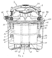
- a filtering device is on the whole shown with the reference 100.
- the device 100 comprises a container 1, provided with a closing lid 10. At the closing lid 10 there are provided an inlet 60 for the water coming from the pond, an outlet 61 for the delivery of the filtered water to the pond and an outlet 62 for delivery water during the rinsing step, which will be described in details in the following.
- a filtering element 2 is placed inside the container 1, made, e.g., in spongy materials and, in particular, could be composed of a set of overlapped filtering elements 2.
- the filtering element 2 is comprised between two supporting surfaces 11, 12 which could be brought the one near the other so as to compress the filtering element 2, as will be seen in the following.
- upper support surface 12 the surface closest to the lid 10 and lower support surface 11 the one opposed thereto.
- the device 100 is used laying on the ground or, preferably, underground, so that the lid is placed at the same level of the ground and substantially parallel thereto.
- the device further comprises actuating means 3 allowing to vary the distance between the supporting surfaces 11 and 12.
- the actuating means 3 could selectively operate according two different modes, a first one in which their motion is unrelated to the motion of the surfaces 11 and 12 and a second one in which they move integral with the upper surface 12.
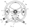
- actuating means 3 comprises a handle 31 connected to two oblong elements 32 developing inside container 1.
- the oblong elements 32 are free to slide inside suitable holes provided on the lid 1 - not shown in figure - so that the handle 31 could be partially moved away from the lid 10.
- Reversible connecting means 33 are provided between the actuating means and the supporting surface 12 at respective ends of the oblong elements 32.
- Such reversible connecting means 33 could selectively engage in suitable seats 13 provided on the supporting surface 12, thus either making the actuating means 3 integral with the surface 12, or disengage from them, so as to make the surface 12 unrelated to the actuating means 3.
- Such reversible connecting means 33 could, e.g., be formed by a shape coupling. More precisely, in the present embodiment, the reversible connecting means comprises pivoting blocks 33, pivoting about an axis substantially corresponding to the longitudinal direction of the oblong elements 32. Knobs 34 are placed at the joint between the handle 31 and the oblong elements 32, allowing to move the blocks 33 about the above mentioned axis.
- blocks 33 have a substantially rectangular section that could engage with the seats 13, the latter having a complementary shape. By rotating the knobs 34 either the blocks 33 could slide within the seats 13 or it will be possible to avoid the passage thereof.
- the handle 31 is placed near the lid 10.
- the handle 31 and thus the actuating means 3 are moved away from the lid 10 until the connecting means 33 slides over the seats 13, placing the actuating means 3 in an operative configuration.
- the connecting means could be rotated by the knobs 34 in order to pass over the seats 13, as can be seen in figure 4B .
- the connecting means 33 are pivoted so that they engage in the seats 13. More generally, in this step of the cleaning method of the filtering device, the actuating means 3 are made integral to the surface 12, at least when they are moved towards the lid 10 again.
- the upper surface 12 will be also moved, approaching the lower surface 11, as could be seen in figure 4D . Accordingly, the filtering element 2, which is encompassed between the two surfaces 11 and 12, will be compressed, discharging impurities and the dirt collected during the filtering of water.
- the device keep on introducing water in the container 1 even when the filtering element 2 is compressed and, during this step, the water is preferably discharged by the outlet 62, so that it is not introduced again in the pond.
- the device 100 has a leverage 5 allowing to select either the outlet 61 or 62 according to the fact that the device is in the filtering step or in the rinsing step.
- leverage 5 allowing to select either the outlet 61 or 62 according to the fact that the device is in the filtering step or in the rinsing step.
- the handle 31 After having carried out the rinsing of the filtering element 2, the handle 31 is then raised again, thus also raising the supporting surface 12, and allowing the filtering element 2 to expand once again, as shown in figure 4E . Finally, the supporting surface 12 can be disengaged from the actuating means 3 operating on the knobs 34 and thus on the connecting means 33, so that it possible to lower the handle once again.
- the filtering element 2 is preferably annularly shaped and it is held on the surfaces 11 and 12 by means of respective holding walls 111 and 121, better shown in figure 1 .
- the device 100 further comprises a discharge central duct 4 connected to the outlet 61 and 62, extending from the lid 10 until it goes over the lower surface 11.
- annular central channel 41 between the filtering element 2 and the discharge central duct 4 is defined. Therefore, as shown in figure 3 , water in the pond is delivered inside the container 1 in a collecting chamber 42, it passes through the filtering element 2, it is delivered in the external channel 41 and then it flows inside the discharge central duct 4.
- the filtering device allows to compress the filtering element 2 just pushing the actuating means 3, in particular the handle 31, towards the filtering element 2. Therefore, this operation do not need the pulling any movable part of the device, thus avoiding any uncomfortable effort for the user, as happens with known devices.
- the compression of the filtering element 2 is achieved by pushing downwards the handle, as the device is placed on the ground in an upright position, nevertheless, also different position could be envisaged.
- the device could be resting on the ground on a side thereof so that the actuating means 3 moves horizontally.
- the actuating means 3 should be pushed towards the filtering element 2 for compressing and rinsing it. Accordingly, again any pulling movement, as required in the known devices, is avoided.
- the device according the present invention is suitable for pushing Such operation could be also carried out by pushing the handle with a foot, therefore without stressing excessively the back of the user.
Landscapes
- Chemical & Material Sciences (AREA)
- Chemical Kinetics & Catalysis (AREA)
- Life Sciences & Earth Sciences (AREA)
- Environmental Sciences (AREA)
- Marine Sciences & Fisheries (AREA)
- Animal Husbandry (AREA)
- Biodiversity & Conservation Biology (AREA)
- Filtration Of Liquid (AREA)
Claims (15)
- Filtervorrichtung (100) für Teiche oder dergleichen, umfassend ein Filterelement (2), das zwischen einer ersten und einer zweiten Abstützfläche (11, 12) angeordnet ist, wobei der Abstand zwischen den Abstützflächen (11, 12) verstellbar ist, um das Filterelement (2) zusammenzudrücken, indem die Abstützflächen (11, 12) nah zueinander bewegt werden, und eine Betätigungseinrichtung (3), die eingerichtet ist, den Abstand zwischen den Abstützflächen (11, 12) zu ändern, dadurch gekennzeichnet, dass diese eine umkehrbare Verbindungseinrichtung (33) umfasst, die eingerichtet ist, eine Verbindung zwischen der Betätigungseinrichtung (3) und der zweiten Abstützfläche (12) selektiv bereitzustellen, so dass sich die Betätigungseinrichtung (3) alternativ:• unabhängig von der Bewegung der Abstützflächen (11, 12) bewegen kann, um in eine funktionsfähige Konfiguration gestellt zu werden; und• integral mit der zweiten Abstützfläche (12) bewegen kann, um den Abstand zwischen den Abstützflächen (11, 12) zu ändern, um das Filterelement (2) zusammenzudrücken,wobei das Filterelement (2) zusammengedrückt wird, indem die Betätigungseinrichtung (3) in Richtung des Filterelements (2) gedrückt wird.
- Filtervorrichtung gemäß Anspruch 1, wobei die umkehrbaren Verbindungseinrichtungen (33) durch eine formschlüssige Verbindung mit der zweiten Abstützfläche (12) gebildet sind.
- Filtervorrichtung gemäß Anspruch 1 oder 2, wobei die umkehrbaren Verbindungseinrichtungen schwenkbare Blöcke (33) umfassen, die mittels länglicher Elemente (32) mit der Betätigungseinrichtung (3) schwenkbar verbunden sind, wobei die schwenkbaren Blöcke (33) in Eingriff mit passenden Sitzen (13) der zweiten Abstützfläche (12) bringbar sind.
- Filtervorrichtung gemäß einem der Ansprüche 1 bis 3, wobei die Betätigungseinrichtung (3) einen Handgriff (31) umfasst.
- Filtervorrichtung gemäß der Ansprüche 3 und 4, wobei der Handgriff (31) mit den länglichen Elementen (32) verbunden ist.
- Filtervorrichtung gemäß einem der Ansprüche 1 bis 5, wobei die Betätigungseinrichtung (3) Knöpfe (34) zum Wirken auf die Verbindungseinrichtung (33) umfasst.
- Filtervorrichtung gemäß einem der vorangehenden Ansprüche, umfassend einen zentralen Abgabeschacht (4), wobei sich das Filterelement (2) zu Haltewänden (111, 112) der Abstützflächen (11, 12) erstreckt, um einen ringförmigen Zentralkanal (41) festzulegen.
- Filtervorrichtung gemäß Anspruch 7, wobei das Wasser, das durch das Filterelement (2) abgegeben wird, im ringförmigen Zentralkanal (41) gesammelt und dann zum zentralen Abgabeschacht (4) zugeführt wird.
- Filtervorrichtung gemäß einem der vorangehenden Ansprüche, umfassend einen Behälter (1), der das Filterelement (2) und die Abstützflächen (11, 12) aufnimmt, wobei die Betätigungseinrichtung (3) relativ zum Behälter (1) beweglich ist, so dass das Filterelement zusammengedrückt wird, indem die Betätigungseinrichtung (3) in den Behälter gedrückt wird.
- Filtervorrichtung gemäß Anspruch 9, wobei der Behälter (1) einen entsprechenden Deckel (10) umfasst, wobei die Betätigungseinrichtung (3) verschiebbar auf dem Deckel (10) ist.
- Filtervorrichtung gemäß Anspruch 10, wobei die Betätigungseinrichtung in der funktionsfähigen Konfiguration (3) vom Deckel (10) fort und nah zum Deckel (10) zum Zusammendrücken des Filterelements (2) bewegt wird.
- Ein Reinigungsverfahren einer Filtervorrichtung (100), wobei die Filtervorrichtung (100) ein Filterelement (2) umfasst, das zwischen einer ersten und einer zweiten Abstützfläche (11, 12) umfasst ist, und eine Betätigungseinrichtung (3), die alternativ geeignet ist, sich unabhängig von der Bewegung der Abstützflächen (11, 12) zu bewegen und sich zusammen mit einer zweiten Abstützfläche (12) der Abstützflächen (11, 12) zu bewegen, um den Abstand zwischen den Abstützflächen (11, 12) zu ändern, wobei dieses Verfahren die Schritten umfasst:- Einstellen der Betätigungseinrichtung (3) in eine funktionsfähige Konfiguration;- Verbinden der Betätigungseinrichtung (3) mit der zweiten Abstützfläche (12), um die Betätigungseinrichtung (3) integral mit der zweiten Abstützfläche (12) zu machen;- Bewegen der Abstützflächen (11, 12) nah zueinander, indem die Betätigungseinrichtung (3) in Richtung des Filterelements (2) gedrückt wird, um das Filterelement (2) zusammenzudrücken;- Spülen des Filterelements (2).
- Reinigungsverfahren einer Filtervorrichtung (100) gemäß Anspruch 12, wobei der Schritt des Einstellens der Betätigungseinrichtung (3) in eine funktionsfähige Konfiguration einen Schritt des Anhebens der Betätigungseinrichtung (3) umfasst.
- Verfahren gemäß Anspruch 12 oder 13, wobei der Schritt des Verbindens der Betätigungseinrichtung (3) mit der zweiten Abstützfläche (12) einen Schritt des Eingreifens von umkehrbaren Verbindungselementen (33) mit entsprechenden Sitzen (13) der Abstützfläche (12) umfasst.
- Verfahren gemäß einem der Ansprüche 12 bis 14, wobei der Schritt des Zusammendrückens des Filterelements (2) ausgeführt wird, indem die Betätigungseinrichtung (3) zusammen mit der zweiten Abstützfläche (12) abgesenkt wird.
Priority Applications (2)
| Application Number | Priority Date | Filing Date | Title |
|---|---|---|---|
| PL09787024T PL2334400T3 (pl) | 2008-08-26 | 2009-08-26 | Urządzenie filtracyjne dla stawów i tym podobnych |
| EP09787024.0A EP2334400B1 (de) | 2008-08-26 | 2009-08-26 | Filtervorrichtung für teichen und dergleichen |
Applications Claiming Priority (3)
| Application Number | Priority Date | Filing Date | Title |
|---|---|---|---|
| EP08425573A EP2161064A1 (de) | 2008-08-26 | 2008-08-26 | Filtervorrichtung für Teichen und dergleichen |
| PCT/IB2009/053741 WO2010023631A1 (en) | 2008-08-26 | 2009-08-26 | Filtering device for ponds and the like |
| EP09787024.0A EP2334400B1 (de) | 2008-08-26 | 2009-08-26 | Filtervorrichtung für teichen und dergleichen |
Publications (2)
| Publication Number | Publication Date |
|---|---|
| EP2334400A1 EP2334400A1 (de) | 2011-06-22 |
| EP2334400B1 true EP2334400B1 (de) | 2013-09-04 |
Family
ID=40263010
Family Applications (2)
| Application Number | Title | Priority Date | Filing Date |
|---|---|---|---|
| EP08425573A Withdrawn EP2161064A1 (de) | 2008-08-26 | 2008-08-26 | Filtervorrichtung für Teichen und dergleichen |
| EP09787024.0A Not-in-force EP2334400B1 (de) | 2008-08-26 | 2009-08-26 | Filtervorrichtung für teichen und dergleichen |
Family Applications Before (1)
| Application Number | Title | Priority Date | Filing Date |
|---|---|---|---|
| EP08425573A Withdrawn EP2161064A1 (de) | 2008-08-26 | 2008-08-26 | Filtervorrichtung für Teichen und dergleichen |
Country Status (5)
| Country | Link |
|---|---|
| US (1) | US9066503B2 (de) |
| EP (2) | EP2161064A1 (de) |
| CN (1) | CN102164648B (de) |
| PL (1) | PL2334400T3 (de) |
| WO (1) | WO2010023631A1 (de) |
Families Citing this family (3)
| Publication number | Priority date | Publication date | Assignee | Title |
|---|---|---|---|---|
| DE202010011286U1 (de) * | 2010-08-11 | 2010-11-04 | Oase Gmbh | Filtervorrichtung |
| US9016290B2 (en) | 2011-02-24 | 2015-04-28 | Joseph E. Kovarik | Apparatus for removing a layer of sediment which has settled on the bottom of a pond |
| CN109399843B (zh) * | 2018-12-05 | 2024-05-17 | 邵养珍 | 一种水过滤装置及用于池塘水过滤的方法 |
Family Cites Families (9)
| Publication number | Priority date | Publication date | Assignee | Title |
|---|---|---|---|---|
| US515769A (en) * | 1894-03-06 | Anthony harris | ||
| US2253516A (en) * | 1938-08-11 | 1941-08-26 | James F Haldeman | Aerating and filtering device for aquariums |
| US4022694A (en) * | 1974-05-06 | 1977-05-10 | Hydronautics, Incorporated | Oil-water separation apparatus |
| JPS6038010B2 (ja) * | 1977-12-28 | 1985-08-29 | キヤノン株式会社 | サ−マルヘツド |
| JPS6038010A (ja) * | 1983-08-11 | 1985-02-27 | Midori Watanabe | 濾過装置 |
| US4579657A (en) * | 1984-11-08 | 1986-04-01 | Filmax, Incorporated | Fluid filter and method of construction |
| ATE171387T1 (de) * | 1993-12-21 | 1998-10-15 | Genera Tech Ltd | Verfahren und vorrichtung zur filtrierung |
| TWI221406B (en) | 2001-07-30 | 2004-10-01 | Epix Medical Inc | Systems and methods for targeted magnetic resonance imaging of the vascular system |
| DE10142092A1 (de) | 2001-08-30 | 2003-04-03 | Oase Wuebker Gmbh & Co Kg | Filtervorrichtung für Gartenteiche oder dergleichen |
-
2008
- 2008-08-26 EP EP08425573A patent/EP2161064A1/de not_active Withdrawn
-
2009
- 2009-08-26 WO PCT/IB2009/053741 patent/WO2010023631A1/en not_active Ceased
- 2009-08-26 EP EP09787024.0A patent/EP2334400B1/de not_active Not-in-force
- 2009-08-26 US US13/061,138 patent/US9066503B2/en active Active
- 2009-08-26 PL PL09787024T patent/PL2334400T3/pl unknown
- 2009-08-26 CN CN2009801380927A patent/CN102164648B/zh active Active
Also Published As
| Publication number | Publication date |
|---|---|
| EP2334400A1 (de) | 2011-06-22 |
| EP2161064A1 (de) | 2010-03-10 |
| US20110203981A1 (en) | 2011-08-25 |
| WO2010023631A1 (en) | 2010-03-04 |
| CN102164648A (zh) | 2011-08-24 |
| PL2334400T3 (pl) | 2014-02-28 |
| US9066503B2 (en) | 2015-06-30 |
| CN102164648B (zh) | 2013-11-06 |
Similar Documents
| Publication | Publication Date | Title |
|---|---|---|
| EP2334400B1 (de) | Filtervorrichtung für teichen und dergleichen | |
| MX2007010356A (es) | Filtro terciario. | |
| KR20180065343A (ko) | 이동식 복합 채밀장치 | |
| EP2662011A1 (de) | Sauggerät | |
| CN117142570A (zh) | 便于分离杂物的污水处理设备 | |
| CN114534330B (zh) | 一种建筑工地污水过滤处理装置 | |
| EP1275305B1 (de) | Filtervorrichtung für flüssige substanzen geeignet für den einsatz in fleisch-einspritzmaschinen | |
| CN211462252U (zh) | 一种市政排水管中的过滤装置 | |
| CN113893914B (zh) | 一种骨科用石膏原料破碎碾磨装置 | |
| CN115949187B (zh) | 绿色建筑 | |
| CN219679325U (zh) | 一种滴灌培植装置 | |
| DE202012010101U1 (de) | Espressokaffeemaschine, insbesondere Espressovollautomat | |
| CN113818517B (zh) | 一种市政用具有喷洒功能的雨水收集装置 | |
| CN208594173U (zh) | 一种河道排污口污水处理装置 | |
| WO2006046037A1 (en) | Pond filters | |
| CN114506936A (zh) | 污水过滤装置 | |
| CN208667137U (zh) | 一种家用式便于清理可二次过滤的污水处理设备 | |
| CN206591613U (zh) | 厨房排水用不锈钢地沟 | |
| CN221788498U (zh) | 一种景区排水过滤装置 | |
| WO2012153088A1 (en) | A mobile toilet facility | |
| CN109169305A (zh) | 一种宠物猫用自动厕所 | |
| CN118698216A (zh) | 一种蜂蜜过滤装置及其使用方法 | |
| US7182868B2 (en) | Device for filtering fluid substances, used for a meat materials injecting machine | |
| CN208761389U (zh) | 一种整形用废液收集装置 | |
| CN118847603A (zh) | 一种中药清洗机 |
Legal Events
| Date | Code | Title | Description |
|---|---|---|---|
| PUAI | Public reference made under article 153(3) epc to a published international application that has entered the european phase |
Free format text: ORIGINAL CODE: 0009012 |
|
| 17P | Request for examination filed |
Effective date: 20110325 |
|
| AK | Designated contracting states |
Kind code of ref document: A1 Designated state(s): AT BE BG CH CY CZ DE DK EE ES FI FR GB GR HR HU IE IS IT LI LT LU LV MC MK MT NL NO PL PT RO SE SI SK SM TR |
|
| AX | Request for extension of the european patent |
Extension state: AL BA RS |
|
| DAX | Request for extension of the european patent (deleted) | ||
| GRAP | Despatch of communication of intention to grant a patent |
Free format text: ORIGINAL CODE: EPIDOSNIGR1 |
|
| INTG | Intention to grant announced |
Effective date: 20130603 |
|
| GRAS | Grant fee paid |
Free format text: ORIGINAL CODE: EPIDOSNIGR3 |
|
| GRAA | (expected) grant |
Free format text: ORIGINAL CODE: 0009210 |
|
| AK | Designated contracting states |
Kind code of ref document: B1 Designated state(s): AT BE BG CH CY CZ DE DK EE ES FI FR GB GR HR HU IE IS IT LI LT LU LV MC MK MT NL NO PL PT RO SE SI SK SM TR |
|
| REG | Reference to a national code |
Ref country code: GB Ref legal event code: FG4D |
|
| REG | Reference to a national code |
Ref country code: CH Ref legal event code: EP |
|
| REG | Reference to a national code |
Ref country code: AT Ref legal event code: REF Ref document number: 630162 Country of ref document: AT Kind code of ref document: T Effective date: 20130915 |
|
| REG | Reference to a national code |
Ref country code: IE Ref legal event code: FG4D |
|
| REG | Reference to a national code |
Ref country code: DE Ref legal event code: R096 Ref document number: 602009018578 Country of ref document: DE Effective date: 20131031 |
|
| REG | Reference to a national code |
Ref country code: NL Ref legal event code: T3 |
|
| REG | Reference to a national code |
Ref country code: AT Ref legal event code: MK05 Ref document number: 630162 Country of ref document: AT Kind code of ref document: T Effective date: 20130904 |
|
| PG25 | Lapsed in a contracting state [announced via postgrant information from national office to epo] |
Ref country code: AT Free format text: LAPSE BECAUSE OF FAILURE TO SUBMIT A TRANSLATION OF THE DESCRIPTION OR TO PAY THE FEE WITHIN THE PRESCRIBED TIME-LIMIT Effective date: 20130904 Ref country code: NO Free format text: LAPSE BECAUSE OF FAILURE TO SUBMIT A TRANSLATION OF THE DESCRIPTION OR TO PAY THE FEE WITHIN THE PRESCRIBED TIME-LIMIT Effective date: 20131204 Ref country code: LT Free format text: LAPSE BECAUSE OF FAILURE TO SUBMIT A TRANSLATION OF THE DESCRIPTION OR TO PAY THE FEE WITHIN THE PRESCRIBED TIME-LIMIT Effective date: 20130904 Ref country code: HR Free format text: LAPSE BECAUSE OF FAILURE TO SUBMIT A TRANSLATION OF THE DESCRIPTION OR TO PAY THE FEE WITHIN THE PRESCRIBED TIME-LIMIT Effective date: 20130904 Ref country code: CY Free format text: LAPSE BECAUSE OF FAILURE TO SUBMIT A TRANSLATION OF THE DESCRIPTION OR TO PAY THE FEE WITHIN THE PRESCRIBED TIME-LIMIT Effective date: 20130724 Ref country code: SE Free format text: LAPSE BECAUSE OF FAILURE TO SUBMIT A TRANSLATION OF THE DESCRIPTION OR TO PAY THE FEE WITHIN THE PRESCRIBED TIME-LIMIT Effective date: 20130904 |
|
| REG | Reference to a national code |
Ref country code: LT Ref legal event code: MG4D |
|
| PG25 | Lapsed in a contracting state [announced via postgrant information from national office to epo] |
Ref country code: FI Free format text: LAPSE BECAUSE OF FAILURE TO SUBMIT A TRANSLATION OF THE DESCRIPTION OR TO PAY THE FEE WITHIN THE PRESCRIBED TIME-LIMIT Effective date: 20130904 Ref country code: SI Free format text: LAPSE BECAUSE OF FAILURE TO SUBMIT A TRANSLATION OF THE DESCRIPTION OR TO PAY THE FEE WITHIN THE PRESCRIBED TIME-LIMIT Effective date: 20130904 Ref country code: LV Free format text: LAPSE BECAUSE OF FAILURE TO SUBMIT A TRANSLATION OF THE DESCRIPTION OR TO PAY THE FEE WITHIN THE PRESCRIBED TIME-LIMIT Effective date: 20130904 Ref country code: GR Free format text: LAPSE BECAUSE OF FAILURE TO SUBMIT A TRANSLATION OF THE DESCRIPTION OR TO PAY THE FEE WITHIN THE PRESCRIBED TIME-LIMIT Effective date: 20131205 |
|
| REG | Reference to a national code |
Ref country code: PL Ref legal event code: T3 |
|
| PG25 | Lapsed in a contracting state [announced via postgrant information from national office to epo] |
Ref country code: CY Free format text: LAPSE BECAUSE OF FAILURE TO SUBMIT A TRANSLATION OF THE DESCRIPTION OR TO PAY THE FEE WITHIN THE PRESCRIBED TIME-LIMIT Effective date: 20130904 Ref country code: BE Free format text: LAPSE BECAUSE OF FAILURE TO SUBMIT A TRANSLATION OF THE DESCRIPTION OR TO PAY THE FEE WITHIN THE PRESCRIBED TIME-LIMIT Effective date: 20130904 |
|
| PG25 | Lapsed in a contracting state [announced via postgrant information from national office to epo] |
Ref country code: RO Free format text: LAPSE BECAUSE OF FAILURE TO SUBMIT A TRANSLATION OF THE DESCRIPTION OR TO PAY THE FEE WITHIN THE PRESCRIBED TIME-LIMIT Effective date: 20130904 Ref country code: CZ Free format text: LAPSE BECAUSE OF FAILURE TO SUBMIT A TRANSLATION OF THE DESCRIPTION OR TO PAY THE FEE WITHIN THE PRESCRIBED TIME-LIMIT Effective date: 20130904 Ref country code: IS Free format text: LAPSE BECAUSE OF FAILURE TO SUBMIT A TRANSLATION OF THE DESCRIPTION OR TO PAY THE FEE WITHIN THE PRESCRIBED TIME-LIMIT Effective date: 20140104 Ref country code: EE Free format text: LAPSE BECAUSE OF FAILURE TO SUBMIT A TRANSLATION OF THE DESCRIPTION OR TO PAY THE FEE WITHIN THE PRESCRIBED TIME-LIMIT Effective date: 20130904 Ref country code: SK Free format text: LAPSE BECAUSE OF FAILURE TO SUBMIT A TRANSLATION OF THE DESCRIPTION OR TO PAY THE FEE WITHIN THE PRESCRIBED TIME-LIMIT Effective date: 20130904 |
|
| PG25 | Lapsed in a contracting state [announced via postgrant information from national office to epo] |
Ref country code: ES Free format text: LAPSE BECAUSE OF FAILURE TO SUBMIT A TRANSLATION OF THE DESCRIPTION OR TO PAY THE FEE WITHIN THE PRESCRIBED TIME-LIMIT Effective date: 20130904 |
|
| REG | Reference to a national code |
Ref country code: DE Ref legal event code: R097 Ref document number: 602009018578 Country of ref document: DE |
|
| PG25 | Lapsed in a contracting state [announced via postgrant information from national office to epo] |
Ref country code: PT Free format text: LAPSE BECAUSE OF FAILURE TO SUBMIT A TRANSLATION OF THE DESCRIPTION OR TO PAY THE FEE WITHIN THE PRESCRIBED TIME-LIMIT Effective date: 20140106 |
|
| PLBE | No opposition filed within time limit |
Free format text: ORIGINAL CODE: 0009261 |
|
| STAA | Information on the status of an ep patent application or granted ep patent |
Free format text: STATUS: NO OPPOSITION FILED WITHIN TIME LIMIT |
|
| 26N | No opposition filed |
Effective date: 20140605 |
|
| REG | Reference to a national code |
Ref country code: DE Ref legal event code: R097 Ref document number: 602009018578 Country of ref document: DE Effective date: 20140605 |
|
| PG25 | Lapsed in a contracting state [announced via postgrant information from national office to epo] |
Ref country code: DK Free format text: LAPSE BECAUSE OF FAILURE TO SUBMIT A TRANSLATION OF THE DESCRIPTION OR TO PAY THE FEE WITHIN THE PRESCRIBED TIME-LIMIT Effective date: 20130904 |
|
| PG25 | Lapsed in a contracting state [announced via postgrant information from national office to epo] |
Ref country code: LU Free format text: LAPSE BECAUSE OF FAILURE TO SUBMIT A TRANSLATION OF THE DESCRIPTION OR TO PAY THE FEE WITHIN THE PRESCRIBED TIME-LIMIT Effective date: 20140826 Ref country code: MC Free format text: LAPSE BECAUSE OF FAILURE TO SUBMIT A TRANSLATION OF THE DESCRIPTION OR TO PAY THE FEE WITHIN THE PRESCRIBED TIME-LIMIT Effective date: 20130904 |
|
| REG | Reference to a national code |
Ref country code: CH Ref legal event code: PL |
|
| GBPC | Gb: european patent ceased through non-payment of renewal fee |
Effective date: 20140826 |
|
| PG25 | Lapsed in a contracting state [announced via postgrant information from national office to epo] |
Ref country code: LI Free format text: LAPSE BECAUSE OF NON-PAYMENT OF DUE FEES Effective date: 20140831 Ref country code: CH Free format text: LAPSE BECAUSE OF NON-PAYMENT OF DUE FEES Effective date: 20140831 |
|
| REG | Reference to a national code |
Ref country code: IE Ref legal event code: MM4A |
|
| PG25 | Lapsed in a contracting state [announced via postgrant information from national office to epo] |
Ref country code: GB Free format text: LAPSE BECAUSE OF NON-PAYMENT OF DUE FEES Effective date: 20140826 |
|
| PG25 | Lapsed in a contracting state [announced via postgrant information from national office to epo] |
Ref country code: IE Free format text: LAPSE BECAUSE OF NON-PAYMENT OF DUE FEES Effective date: 20140826 |
|
| PG25 | Lapsed in a contracting state [announced via postgrant information from national office to epo] |
Ref country code: SM Free format text: LAPSE BECAUSE OF FAILURE TO SUBMIT A TRANSLATION OF THE DESCRIPTION OR TO PAY THE FEE WITHIN THE PRESCRIBED TIME-LIMIT Effective date: 20130904 |
|
| PG25 | Lapsed in a contracting state [announced via postgrant information from national office to epo] |
Ref country code: BG Free format text: LAPSE BECAUSE OF FAILURE TO SUBMIT A TRANSLATION OF THE DESCRIPTION OR TO PAY THE FEE WITHIN THE PRESCRIBED TIME-LIMIT Effective date: 20130904 Ref country code: MT Free format text: LAPSE BECAUSE OF FAILURE TO SUBMIT A TRANSLATION OF THE DESCRIPTION OR TO PAY THE FEE WITHIN THE PRESCRIBED TIME-LIMIT Effective date: 20130904 |
|
| PG25 | Lapsed in a contracting state [announced via postgrant information from national office to epo] |
Ref country code: TR Free format text: LAPSE BECAUSE OF FAILURE TO SUBMIT A TRANSLATION OF THE DESCRIPTION OR TO PAY THE FEE WITHIN THE PRESCRIBED TIME-LIMIT Effective date: 20130904 Ref country code: HU Free format text: LAPSE BECAUSE OF FAILURE TO SUBMIT A TRANSLATION OF THE DESCRIPTION OR TO PAY THE FEE WITHIN THE PRESCRIBED TIME-LIMIT; INVALID AB INITIO Effective date: 20090826 |
|
| REG | Reference to a national code |
Ref country code: FR Ref legal event code: PLFP Year of fee payment: 8 |
|
| PGFP | Annual fee paid to national office [announced via postgrant information from national office to epo] |
Ref country code: FR Payment date: 20160822 Year of fee payment: 8 |
|
| REG | Reference to a national code |
Ref country code: FR Ref legal event code: ST Effective date: 20180430 |
|
| PG25 | Lapsed in a contracting state [announced via postgrant information from national office to epo] |
Ref country code: MK Free format text: LAPSE BECAUSE OF FAILURE TO SUBMIT A TRANSLATION OF THE DESCRIPTION OR TO PAY THE FEE WITHIN THE PRESCRIBED TIME-LIMIT Effective date: 20130904 |
|
| PG25 | Lapsed in a contracting state [announced via postgrant information from national office to epo] |
Ref country code: FR Free format text: LAPSE BECAUSE OF NON-PAYMENT OF DUE FEES Effective date: 20170831 |
|
| PGFP | Annual fee paid to national office [announced via postgrant information from national office to epo] |
Ref country code: NL Payment date: 20220822 Year of fee payment: 14 |
|
| PGFP | Annual fee paid to national office [announced via postgrant information from national office to epo] |
Ref country code: PL Payment date: 20220819 Year of fee payment: 14 |
|
| PGFP | Annual fee paid to national office [announced via postgrant information from national office to epo] |
Ref country code: IT Payment date: 20230703 Year of fee payment: 15 |
|
| REG | Reference to a national code |
Ref country code: NL Ref legal event code: MM Effective date: 20230901 |
|
| PG25 | Lapsed in a contracting state [announced via postgrant information from national office to epo] |
Ref country code: NL Free format text: LAPSE BECAUSE OF NON-PAYMENT OF DUE FEES Effective date: 20230901 |
|
| PG25 | Lapsed in a contracting state [announced via postgrant information from national office to epo] |
Ref country code: NL Free format text: LAPSE BECAUSE OF NON-PAYMENT OF DUE FEES Effective date: 20230901 |
|
| PGFP | Annual fee paid to national office [announced via postgrant information from national office to epo] |
Ref country code: DE Payment date: 20240821 Year of fee payment: 16 |
|
| PG25 | Lapsed in a contracting state [announced via postgrant information from national office to epo] |
Ref country code: PL Free format text: LAPSE BECAUSE OF NON-PAYMENT OF DUE FEES Effective date: 20230826 |
|
| PG25 | Lapsed in a contracting state [announced via postgrant information from national office to epo] |
Ref country code: PL Free format text: LAPSE BECAUSE OF NON-PAYMENT OF DUE FEES Effective date: 20230826 |
|
| PG25 | Lapsed in a contracting state [announced via postgrant information from national office to epo] |
Ref country code: IT Free format text: LAPSE BECAUSE OF NON-PAYMENT OF DUE FEES Effective date: 20240826 |
|
| REG | Reference to a national code |
Ref country code: DE Ref legal event code: R119 Ref document number: 602009018578 Country of ref document: DE |