EP2334083B1 - Verfahren und Vorrichtung zur Kodierung/Dekodierung von Bewegungsvektoren, und Verfahren und Vorrichtung zur Kodierung/Dekodierung von Bildsignalen - Google Patents
Verfahren und Vorrichtung zur Kodierung/Dekodierung von Bewegungsvektoren, und Verfahren und Vorrichtung zur Kodierung/Dekodierung von Bildsignalen Download PDFInfo
- Publication number
- EP2334083B1 EP2334083B1 EP20100012180 EP10012180A EP2334083B1 EP 2334083 B1 EP2334083 B1 EP 2334083B1 EP 20100012180 EP20100012180 EP 20100012180 EP 10012180 A EP10012180 A EP 10012180A EP 2334083 B1 EP2334083 B1 EP 2334083B1
- Authority
- EP
- European Patent Office
- Prior art keywords
- motion vector
- signal
- macroblock
- picture
- motion
- Prior art date
- Legal status (The legal status is an assumption and is not a legal conclusion. Google has not performed a legal analysis and makes no representation as to the accuracy of the status listed.)
- Expired - Lifetime
Links
Images


Classifications
-
- H—ELECTRICITY
- H04—ELECTRIC COMMUNICATION TECHNIQUE
- H04N—PICTORIAL COMMUNICATION, e.g. TELEVISION
- H04N19/00—Methods or arrangements for coding, decoding, compressing or decompressing digital video signals
- H04N19/42—Methods or arrangements for coding, decoding, compressing or decompressing digital video signals characterised by implementation details or hardware specially adapted for video compression or decompression, e.g. dedicated software implementation
- H04N19/43—Hardware specially adapted for motion estimation or compensation
-
- H—ELECTRICITY
- H04—ELECTRIC COMMUNICATION TECHNIQUE
- H04N—PICTORIAL COMMUNICATION, e.g. TELEVISION
- H04N7/00—Television systems
- H04N7/24—Systems for the transmission of television signals using pulse code modulation
- H04N7/52—Systems for transmission of a pulse code modulated video signal with one or more other pulse code modulated signals, e.g. an audio signal or a synchronizing signal
- H04N7/54—Systems for transmission of a pulse code modulated video signal with one or more other pulse code modulated signals, e.g. an audio signal or a synchronizing signal the signals being synchronous
-
- H—ELECTRICITY
- H04—ELECTRIC COMMUNICATION TECHNIQUE
- H04N—PICTORIAL COMMUNICATION, e.g. TELEVISION
- H04N19/00—Methods or arrangements for coding, decoding, compressing or decompressing digital video signals
- H04N19/10—Methods or arrangements for coding, decoding, compressing or decompressing digital video signals using adaptive coding
- H04N19/102—Methods or arrangements for coding, decoding, compressing or decompressing digital video signals using adaptive coding characterised by the element, parameter or selection affected or controlled by the adaptive coding
- H04N19/132—Sampling, masking or truncation of coding units, e.g. adaptive resampling, frame skipping, frame interpolation or high-frequency transform coefficient masking
-
- H—ELECTRICITY
- H04—ELECTRIC COMMUNICATION TECHNIQUE
- H04N—PICTORIAL COMMUNICATION, e.g. TELEVISION
- H04N19/00—Methods or arrangements for coding, decoding, compressing or decompressing digital video signals
- H04N19/10—Methods or arrangements for coding, decoding, compressing or decompressing digital video signals using adaptive coding
- H04N19/169—Methods or arrangements for coding, decoding, compressing or decompressing digital video signals using adaptive coding characterised by the coding unit, i.e. the structural portion or semantic portion of the video signal being the object or the subject of the adaptive coding
- H04N19/17—Methods or arrangements for coding, decoding, compressing or decompressing digital video signals using adaptive coding characterised by the coding unit, i.e. the structural portion or semantic portion of the video signal being the object or the subject of the adaptive coding the unit being an image region, e.g. an object
- H04N19/176—Methods or arrangements for coding, decoding, compressing or decompressing digital video signals using adaptive coding characterised by the coding unit, i.e. the structural portion or semantic portion of the video signal being the object or the subject of the adaptive coding the unit being an image region, e.g. an object the region being a block, e.g. a macroblock
-
- H—ELECTRICITY
- H04—ELECTRIC COMMUNICATION TECHNIQUE
- H04N—PICTORIAL COMMUNICATION, e.g. TELEVISION
- H04N19/00—Methods or arrangements for coding, decoding, compressing or decompressing digital video signals
- H04N19/50—Methods or arrangements for coding, decoding, compressing or decompressing digital video signals using predictive coding
- H04N19/503—Methods or arrangements for coding, decoding, compressing or decompressing digital video signals using predictive coding involving temporal prediction
- H04N19/51—Motion estimation or motion compensation
- H04N19/513—Processing of motion vectors
- H04N19/517—Processing of motion vectors by encoding
-
- H—ELECTRICITY
- H04—ELECTRIC COMMUNICATION TECHNIQUE
- H04N—PICTORIAL COMMUNICATION, e.g. TELEVISION
- H04N19/00—Methods or arrangements for coding, decoding, compressing or decompressing digital video signals
- H04N19/50—Methods or arrangements for coding, decoding, compressing or decompressing digital video signals using predictive coding
- H04N19/503—Methods or arrangements for coding, decoding, compressing or decompressing digital video signals using predictive coding involving temporal prediction
- H04N19/51—Motion estimation or motion compensation
- H04N19/577—Motion compensation with bidirectional frame interpolation, i.e. using B-pictures
-
- H—ELECTRICITY
- H04—ELECTRIC COMMUNICATION TECHNIQUE
- H04N—PICTORIAL COMMUNICATION, e.g. TELEVISION
- H04N19/00—Methods or arrangements for coding, decoding, compressing or decompressing digital video signals
- H04N19/60—Methods or arrangements for coding, decoding, compressing or decompressing digital video signals using transform coding
- H04N19/61—Methods or arrangements for coding, decoding, compressing or decompressing digital video signals using transform coding in combination with predictive coding
-
- H—ELECTRICITY
- H04—ELECTRIC COMMUNICATION TECHNIQUE
- H04N—PICTORIAL COMMUNICATION, e.g. TELEVISION
- H04N19/00—Methods or arrangements for coding, decoding, compressing or decompressing digital video signals
- H04N19/10—Methods or arrangements for coding, decoding, compressing or decompressing digital video signals using adaptive coding
- H04N19/102—Methods or arrangements for coding, decoding, compressing or decompressing digital video signals using adaptive coding characterised by the element, parameter or selection affected or controlled by the adaptive coding
- H04N19/103—Selection of coding mode or of prediction mode
- H04N19/107—Selection of coding mode or of prediction mode between spatial and temporal predictive coding, e.g. picture refresh
Definitions
- This invention relates to a motion vector difference determination (calculation) method and a motion vector difference determination (calculation) element for determining (calculating) a difference between motion vectors by motion compensating prediction of a moving picture, a method for determination of reconstructed motion vector from difference and an element for determination of reconstructed motion vector from difference, and a moving picture coding apparatus and a moving picture decoding apparatus for coding and decoding a moving picture signal to which determination of difference and determination of reconstructed motion vector from difference are applied, respectively.
- the motion compensating predictive coding is a method utilizing correlation in a time base direction of a picture signal. This method predicts a currently inputted picture (picture of current frame) from a known picture signal already decoded and reproduced (picture signal of past frame) to move the known picture signal decoded and reproduced (picture signal of past frame) in correspondence with motion of signal to transmit only motion information (motion vector MV) at that time and predictive error information at that time, thus to compress information quantity required for coding.
- motion vector MV motion vector
- MPEG Motion compensating predictive coding and decoding methods as described above.
- This MPEG1 is a popular name of the moving picture coding system which has progressed in WG (Working Group) 11 of SC (Sub Committee) 29 of JTC (Joint Technical Committee) 1 of so called ISO (International Standardization Organization) and IEC (International Electrotechnical Commission).
- MPEG1 has intraframe and interframe coding processing, and the motion compensating predictive coding is used in the case of the interframe coding processing.
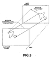
- An example of motion compensating prediction at this time is shown in FIG. 10 .
- one frame (picture) is divided into small blocks (called macro blocks (MB) and each is comprised of 16 lines x 16 pixels) to carry out motion compensating predictive coding in units of those small blocks.
- macro blocks (MB) small blocks
- each is comprised of 16 lines x 16 pixels
- FIG. 11 A more practical example of motion compensation at this time is shown in FIG. 11 .
- P picture (to be coded) indicated by P in the figure jumping over several pictures is predictive-coded by using I picture indicated by I in the figure or any other P picture.
- Such predictive coding operation is cyclically executed.
- B pictures indicated by B in the figure put between P pictures, I pictures or between picture and I picture are sequentially predictive-coded from P picture or I picture before and after those B pictures.
- I picture is intraframe coded picture which is prepared without use of motion compensation.
- arrows (except for arrow indicating direction of time t) in Fig. 11 indicate directions of motion predictions.
- an optimum one of the first and fourth motion compensation modes is selected in units of macroblocks. At this time, as past frame to which reference is made at the time of motion compensating prediction with respect to picture of current frame, one frame exists. Further, in the B picture, an optimum one of the first to fourth motion compensating modes is selected in units of macroblocks. At this time, as past frame and future frame to which reference is made at the time of motion compensating prediction with respect to picture of current frame, one frames respectively exist.
- one motion vector which makes reference to the past frame exists in prediction in the first motion compensating mode.
- prediction in the second motion compensating mode one motion vector which makes reference to the future frame exists.
- prediction in the third motion compensating mode one motion vectors which make reference to both past and future frames respectively exist.
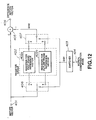
- motion vectors delivered in units of these macroblocks are caused to undergo determination (calculation) of difference by difference determination (calculation) element shown in FIF. 12 by making use of the fact that information of motion vector given in units of macroblocks have high spatial correlation, and difference information thus obtained is transmitted.
- terminal 404 is supplied with motion compensation mode signals given as four kinds of the first to fourth motion compensating modes, and terminal 401 is supplied with a motion vector signal currently inputted.
- the currently inputted motion vector signal is sent to common terminal of switch 406 and adding input terminal of difference circuit 405, and the motion compensating mode signal is sent to switcher 403.
- Selected (switched) terminal a of the switch 406 is connected to input terminal of register 402a for past frame reference vector of register group 402, and selected terminal b is connected to input terminal of register 402b for future frame reference vector of register group 402. Further, output terminal of register 402a for past frame reference vector of register group 402 is connected to selected terminal a of switch 407, and output terminal of the register 402b for future frame reference vector is connected to selected terminal b of switch 407.
- These switches 406 and 407 are of a structure such that any one of the selected terminals a and b is selected in accordance with register switching signal S401 outputted from switcher 403 supplied with the motion compensating mode signal. An output of the switch 407 is sent to subtracting input terminal of the difference circuit 405.
- the difference circuit 405 takes a difference between motion vector signal S402 which has been read out through the switch 407 from register group 402 in accordance with register switching signal S401 outputted from the switcher 403 and motion vector signal from the terminal 401.
- a difference by the difference circuit 405 is outputted from terminal 408 as a difference motion vector from the difference determination circuit.
- the motion vector signal currently inputted is overwritten into register 402a or 402b designated by register switching signal S401 through the switch 406, and is newly stored thereinto.
- motion vectors making reference to past frame and motion vectors making reference to future frame are caused to independently undergo processing for determination of difference.
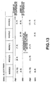
- FIG. 13 A more practical example of the operation of the above-described difference determination element is shown in FIG. 13 .
- X-component of (X, Y) of motion vector indicates motion in a horizontal direction and Y-component thereof indicates motion in a vertical direction. Positive values are given to motions spatially in right direction and in lower direction, and negative values are given to motions in left direction and in upper direction. In this example, (0, 0) is given as an initial value at the time of determination of difference.
- FMV represents past frame reference motion vector
- BMV represents future frame reference motion vector.
- mode (1) represents motion compensation mode of forward prediction
- mode (2) represents motion compensation mode of backward prediction
- mode (3) represents motion compensation mode of bidirectional prediction.
- difference motion vector in small block of mode (2) adjacent on the right side is (9, 10)
- difference motion vector becomes equal to (1, 2) of (9, 10) - (8, 8)
- difference motion vectors thereof become equal to (-2, -2) of (5, 4) - (7, 6) and (-1, -1) of (8, 9) - (9, 10).
- Fig. 14 An inverse difference determination element for reconstructing motion vector from motion vector caused to be represented by difference vector, which is a configuration complementary to the difference determination element shown in FIG. 13 , is shown in Fig. 14 .
- terminal 414 is supplied with motion compensation mode signals given as four kinds of the first to fourth motion compensating modes, and terminal 408 is supplied with the difference motion vector signal currently inputted.
- the difference motion vector signal is sent to one adding input terminal of adding circuit 409, and the motion compensation mode signal is sent to switcher 413.
- selected terminal a of switch 411 is connected to output terminal of register 410a for past frame reference vector of register group 410, and selected terminal b is connected to output terminal of register 410b for future frame reference vector.
- This switch 411 is of a structure such that any one of the selected terminals a and b is selected in accordance with register switching signal S403 outputted from switcher 413 supplied with the motion compensation mode signal. Common terminal of the switch 411 is connected to the other adding input terminal of the adding circuit 409.
- the adding circuit 409 takes an addition of motion vector signal S404 which has been read out through the switch 411 from register group 410 in accordance with register switching signal S403 outputted from the switcher 413 and difference motion vector signal from the terminal 408.
- An addition output of the adding circuit 409 is outputted from terminal 415 as reconstructed motion vector signal from the inverse difference determination element.
- the reconstructed motion vector signal from the adding circuit 409 is sent also to common terminal of switch 412.
- This switch 412 is of a structure such that any one of selected terminals a and b is selected on the basis of the register switching signal S403.
- Selected terminal a is connected to register 410a for past frame reference vector of the register group 410 and selected terminal b is connected to register 410b for future frame reference vector.
- the MPEG1 is moving picture coding method suitable for non-interlaced picture, it cannot be said that the MPEG1 is necessarily suitable for coding of interlaced signal such as so called NTSC system or PAL system, etc. which is a television signal. This was problem.
- FIG. 15 a method of adaptively carrying out switching between unit for handling picture in frame and that in field is adopted.
- fr indicates frame
- fi indicates field
- arrow FRP indicates prediction of frame base
- arrow FIP indicates prediction of field base.
- the number of motion vectors given in units of macroblocks is as follows. Namely, in the previously described prediction of the first motion compensating mode, one or more motion vectors which makes reference to past frame (or field) exist; in the prediction of the second motion compensating mode, one or more motion vectors which makes reference to future frame (or field) exist; and in the prediction of the third motion compensating mode, one or more motion vectors which make reference to both frames (or fields) of past and future respectively exist.
- the numbers of motion vectors in respective motion compensating modes are varied in units of macroblocks.
- the first problem is that method used in the MPEGl cannot be applied in encoding motion vector.
- various proposals have been made. They are laid open to public inspection, e.g., on P.32, P.44, P.145, P.148 of ISO-IEC/JTC1/ SC29/WG11 MPEG93/225b Test Model 4 (laid open on February 1993).
- the second problem resides in that handling of skipped macroblock is not clearly shown.
- skipped macroblocks in the MPEG1 are macroblocks as featured below: Namely, they are characterized in that;
- skipped macroblocks will be dealt in the MPEG1 as follows: Namely, in the MPEG1, skipped macroblocks are handled in such a manner that
- decoding processing of skipped macroblock at P picture is copy from past picture
- decoding processing of skipped macroblocks at B picture is copy from macroblock adjacent on the left side decoded immediately before within the same frame.
- the encoder transmits no data.
- the skipped macroblock is important coding technology in view of improvement in coding efficiency.
- a picture to be processed is a sequence of moving pictures
- its content is a scene where still pictures (pictures having very gentle motion) are successive
- most macroblocks can be dealt as skipped macroblocks.
- method for encoding motion vector in motion compensating prediction of the previously described MPEG2 is required to be a method in which handling of skipped macroblock is taken into consideration as well.
- terminal 504 is supplied with mode information of forward, backward or bidirectional prediction as mode signal of motion compensation, information indicating frame prediction or field prediction, etc. as prediction type signal which will be described later, and information indicating frame structure, field structure or progressive as picture structure signal, and is further supplied, in addition to the above; with information indicating the first field (field 1, i.e., e.g., odd field) or the second field (field 2, i.e., e.g., even field) as field motion vector parity signal, information similarly indicating the first field or the second field as predicted field parity signal, and information indicating P picture or B picture as picture coding type signal.
- terminal 501 is supplied with a motion vector signal currently inputted.
- the signal which has been delivered to the terminal 504 is sent to switcher 503. Further, the currently inputted motion vector signal is sent to common terminal of switch 506 through scale converter 509 for implementing a predetermined scale conversion B to the currently inputted motion vector on the basis of scale indication signal SCB from the switcher 503, and is directly sent to adding input terminal of difference circuit 505.
- the switch 506 has selected terminals a to d. Selected terminal a is connected to input terminal of register memory PMV1 of register memory group 502 for storing motion vector which will be described later; selected terminal b is connected to input terminal of register memory PMV2 of register group 502; selected terminal c is connected to input terminal of register memory PMV3; and selected terminal d is connected to input terminal of register memory PMV4.
- output terminal of register memory PMV1 of register memory group 502 for storing motion vector is connected to selected terminal a of switch 507; output terminal of register memory PMV2 of is connected to selected terminal b of switch 507; output terminal of register memory PMV3 is connected to selected terminal c of switch 507; and output terminal of register memory PMV4 is connected to selected terminal d of switch 507.
- These switches 506 and 507 are of a structure such that any one of the selected terminals a to d is selected in accordance with register switching signal outputted from the switcher 503.
- An output of the switch 507 is sent to subtracting input terminal of the difference circuit 505 through scale converter 510 for implementing a predetermined scale conversion A on the basis of scale indication signal SCA from the switcher 503.
- the difference circuit 505 takes a difference between information from the scale converter 510 and motion vector signal from the terminal 501.
- the difference obtained by this difference circuit 505 is outputted from terminal 508 as difference motion vector signal from the difference determination element.
- register memory group 502 comprised of four register memories PMV1 ⁇ PMV4 for storing the motion vector signal is prepared.
- register memory group 502 for storing motion vector
- information of forward motion vector in which reference picture (picture which serves as reference of predictive picture) is the first field and predicted field with respect thereto (field which is to be coded from now on) is the first field is stored into register memory PMV1. Further, information of forward motion vector in which reference picture is the second field and predicted field is the first field is stored into register memory PMV2. Information of forward motion vector in which reference picture is the first field and predicted field is the second field is stored into register memory PMV3. In addition, information of forward motion vector in which reference picture is the second field and predicted field is the second field is stored into register memory PMV4. Namely, in the P picture, the relationship between motion vector signals and respective register memories in which they are stored was determined by combinations of reference pictures and fields to be predicted.
- two register memories PMV are prepared for forward motion vector.
- information of forward motion vector in which reference picture is the first field is stored into register memory PMV1
- information of forward motion vector in which reference picture is the second field is stored into register memory PMV2.
- two register memories PMV are prepared for backward motion vector as well.
- Information of backward motion vector in which reference picture is the first field is stored into register memory PMV3, and information of backward motion vector in which reference picture is the second field is stored into register memory PMV4. Namely, in the B picture, irrespective of whether a field to be predicted is the first field or the second field, motion vector signals in which reference picture and direction of prediction are the same were stored into the same register memory.
- difference determination element in allowing the currently inputted motion vector to be difference vector, an approach is employed to take out the value of register memory PMV corresponding to that motion vector (i.e., PMV in which a motion vector having parity of reference picture and predicted field which are the same as the motion vector is stored in the case where that motion vector is used for coding of P picture; and, PMV in which a motion vector having parity of reference picture and direction of prediction which are same as the motion vector is stored in the case where that motion vector is used for coding of B picture) to implement a predetermined scale conversion A by scale converter 510 thereto as occasion demands (in accordance with scale indication signal SCA) thereafter to carry out calculation between the scale converted value A and the above-mentioned currently inputted motion vector by difference circuit 505.
- scale conversion B is implemented to the value of the currently inputted motion vector by scale converter 509 as occasion demands thereafter to overwrite it into any one of register memories PMV selected and subjected to reference at the time of determination of difference motion vector as described above although not illustrated to newly store it tereinto. Difference determination element is constructed in this way.
- FIG. 17 shows an inverse difference determination element corresponding to difference determination element for motion vector of FIG. 16 .
- terminal 524 is supplied with motion compensation mode signal, prediction type signal, picture structure signal, field motion vector parity signal, predicted field parity signal, and picture coding type signal.
- terminal 518 is supplied with the currently inputted difference motion vector signal.
- selected terminal a of switch 521 is connected to output terminal of register memory PMV1 of motion vector storage register memory group 520 for carrying out storage similar to that of motion vector storage register memory group 502 of FIG. 16 ; selected terminal b is connected to output terminal of register memory PMV2; selected terminal c is connected to output terminal of register memory PMV3; and selected terminal d is connected to output terminal of register memory PMV4.
- This switch 521 is of a structure such that any one of selected terminals a to d is selected in accordance with register switching signal from the switcher 523. Common terminal of this switch 521 is connected to the other adding input terminal of the adding circuit 519 through scale converter 529 for implementing a predetermined scale conversion C to a signal delivered on the basis of scale indication signal SCC from the switcher 123.
- the adding circuit 519 takes an addition of motion vector signal passed through the switch 521 from register memory group 520 in accordance with register switching signal outputted from the switcher 523 and further through scale converter 529 and difference motion vector signal from the terminal 518.
- An addition output of the adding circuit 519 is outputted from terminal 525 as reconstructed motion vector from the inverse difference determination element.
- the reconstructed motion vector signal from the adding circuit 519 is sent also to common terminal of switch 522 through scale converter 530 for implementing a predetermined scale conversion D to a signal delivered on the basis of scale indication signal SCD from the switcher 523.
- This switch 522 is of a structure such that any one of selected terminals a - d is selected on the basis of the register switching signal.
- selected terminal a is connected to input terminal of register memory PMV1 of the register memory group 520
- selected terminal b is connected to input terminal of register memory PMV2
- selected terminal c is connected to input terminal of register memory PMV3
- selected terminal d is connected to input terminal of register memory PMV4.
- the value stored in register memory PMV corresponding to inputted difference motion vector i.e., PMV in which reconstructed motion vector having parity values of reference picture and predicted field which are the same as the difference motion vector is stored in the case where difference motion vector is used for decoding of P picture, or PMV in which reconstructed motion vector having reference picture parity and direction of prediction which are the same as the difference motion vector is stored in the case where difference motion vector is used for decoding of B picture
- corresponding to inputted differential motion vector is taken out to implement scale conversion C to that value by using scale converter 529 as occasion demands thereafter to carry out an addition calculation of that scale converted value and the currently inputted difference motion vector by using adding circuit 519, thus to reconstruct motion vectors corresponding to original motion vector.
- the reconstructed motion vector is caused to undergo scale conversion D by scale converter 530 as occasion demands thereafter to overwrite and newly store the scale converted value into any one of register memories PMV1 - PMV4 selected and subjected to reference at the time of reconstruction of motion vector.
- Inverse difference determination element is constructed in this way.
- picture structure is field structure and predicted field parity is the first field (predicted field is the first field).
- the prediction type is 16x8 Field based prediction in the case of respectively independently carrying out prediction with respect to the area of 16 pixels x 8 lines of the upper portion and the area of 16 pixels x 8 lines of the lower portion.
- motion vector of the upper portion of macroblock MBO is (5, 1) (1)
- motion vector of the lower portion of macroblock MBO is (5, 5) (2)
- motion vector of the upper portion of macroblock MB1 is (5, 5) (3)
- motion vector of the lower portion of macroblock MB1 is (5. 5) (4)
- motion vector of the upper portion of macroblock MB2 is (5. 5) (5)
- motion vector of the lower portion of macroblock MB2 is (5, 5) (6) .
- the picture structure is assumed to be frame structure.
- the prediction type is assumed to be Field based prediction for respectively independently predicting the first field and the second field of macroblock MB (predicted field is assumed to be the first field and the second field).
- the first field of macroblock MB0 is (5, 1) (1)
- motion vector of the second field is (5. 5) (2)
- motion vector of the second field of macroblock MB1 is (5, 5) (3)
- motion vector of the second field is (5, 5) (4)
- motion vector of the second field of macroblock MB2 is (5, 5) (5)
- motion vector of the second field is (5, 5) (6) .
- FIG. 19 shows the operation for reconstructing motion vector from difference motion vector transmitted with respect to B picture.
- picture structure is field structure
- macroblocks MB0, MB1, MB2 are encoded in the forward predictive mode respectively independently in the area of 16 pixels x 8 lines of the upper portion and the area of 16 pixels x 8 lines of the lower portion.
- the area of 16 pixels x 8 lines of the upper portion and the area of 16 pixels x 8 lines of the lower portion are caused to be both single first field.
- the invention is set out in decoding method claim 1 and in the corresponding apparatus for decoding claim 2.
- a moving picture coding apparatus (encoder) according to this invention will be first described with reference to Fig. 1 .
- Picture coding control information input section 30 Information for controlling basic operation of the encoder according to this invention is given from a picture coding control information input section 30, and is stored in picture coding control information storage memory 29. These information are picture frame size, output bit rate of coding information, and the like. These information are outputted from the memory 29 as picture coding control signal S25. Further, picture structure signal S26 (signal for discriminating whether picture structure is frame structure, field structure or progressive) is outputted through the memory 29 from the picture coding information input section 30, and picture coding type signal S27 (signal for discriminating whether picture type is I picture, P picture or B picture) is also outputted therefrom.
- picture structure signal S26 signal for discriminating whether picture structure is frame structure, field structure or progressive
- picture coding type signal S27 signal for discriminating whether picture type is I picture, P picture or B picture
- a picture signal inputted from picture input terminal 10 is delivered to a field memory group 11.
- a vertical synchronizing (sync.) signal S11 which is an input picture synchronizing signal is delivered from input terminal 26, and is then delivered to a reference picture control element 23.
- the picture coding control signal S25, picture structure signal S26, and picture coding type signal S27 are also delivered through terminal 1.
- this reference picture control element 23 receives the vertical synchronizing signal S11, it outputs reference picture indication signal S10 which will be described later, and delivers it to field memory group 11.
- a picture of a picture signal which has been delivered to the field memory group 11 is a picture to be currently coded.
- the field memory group 11 sets or raises picture start flag S22 which will be described later to deliver it to reference picture control element 24 through terminals 2 and 9.
- the reference picture control element 24 outputs reference picture indication signals S12, S13 which will be described later when picture start flag S22 is set to deliver them to field memory group 17. Further, picture start flag S22 caused to be through the terminal 9 is delivered also to an output picture control element 25.
- the output picture control element 25 outputs output picture indication signal S14 which will be described later when the picture start flag S22 is set to deliver it to field memory group 17.
- picture coding control signal S25, picture structure signal S26, and picture coding type signal S27 are delivered to the reference picture control element 24 and the output picture control element 25 through terminal 30.
- a picture signal which has been delivered to the field memory group 11 is sent to a motion predicting circuit 12, and the picture coding control signal S25, picture structure signal S26, and picture coding type signal S27 from the terminal 1 are delivered to the motion predicting circuit 12.
- This motion predicting circuit 12 implements motion prediction of pixels in a picture to be currently coded to picture signal which has been delivered to the field memory group 11 by making reference to past picture and future picture.
- the above-mentioned motion prediction is block matching of a block pixel signal in a picture which is to be currently coded and past picture or future picture to which reference is made, and the size of block is, e.g., 16x16 pixels, 16x8 pixels or 8x8 pixels.
- Past and future reference pictures at this time are designated from field memory group 11 in accordance with reference picture indication signal S10 of motion prediction outputted from reference picture control element 23.
- the motion predicting circuit 12 detects each block position in reference picture in which predictive error in block matching becomes minimum with respect to respective selectable motion compensation modes to deliver motion vector corresponding to that position as motion vector signal S7 to motion compensating circuit 18. It is to be noted that which motion compensating mode can be selected is determined by picture structure signal S26 and picture coding type signal S27.
- the motion predicting circuit 12 delivers, to motion compensating circuit 18, prediction type signal S30, field motion vector reference parity signal S31, sub-motion vector signal S32, and predicted field parity signal S33 as additional information of the motion vector signal S7 as well.
- the prediction type signal S30 is information, e.g., indicating whether motion prediction is carried out by the frame base or the field base, block matching is carried out by 16x16 pixels, 16x8 pixels or 8x8 pixels, motion prediction is DUAL-PRIME or not. It is to be noted that since the details of 8x8 pixel block prediction and DUAL-PRIME are described in the previously described material ISO-IEC/JTC1/SC29/ WG11 MPEG93/225b Test Model 4, their explanation is omitted here.
- the field motion vector reference parity signal S31 is a signal indicating whether a field making reference to vector is the first field (field 1) or the second field (field 2) in the case where motion prediction is carried out by field base.
- the sub-motion vector signal S32 is, e.g., a vector attached signal of DUAL-PRIME and 8x8 pixel block prediction.
- the predicted field parity signal S33 is a signal indicating whether field of destination of prediction (predicted field) of motion vector is the first field or the second field in the case where motion prediction is carried out by field base.
- the motion compensating circuit 18 instructs output of block picture signal S3 positioned at an address designated by motion vector signal S7, prediction type signal S30, field motion vector reference parity signal S31, sub-motion vector signal S32, and predicted field parity signal S33, from field memory group 17 in which pictures already decoded and reproduced (which will be described later) are stored.
- Reference picture at this time is designated from field memory group 17 in accordance with motion compensation reference picture indication signal S12 outputted from reference picture control element 24.
- An output of block picture signal S3 from the motion compensating circuit 18 is caused to be adaptive operation, thus making it possible to carry out switching to an optimum one of selectable motion compensating modes of four kinds of operations described below in unit of macroblocks.
- a mode in which sum total of absolute values of difference values every pixel between respective picture signals S3 outputted in the four kinds of modes and block pixel signal S1 to be currently coded is minimum is selected.
- the mode thus selected is sent to respective components through terminal 3 as motion compensation mode signal S9, motion vector signal S8 at that time, prediction type signal S40, field motion vector reference parity signal S41, sub-motion vector signal S42, and predicted field parity signal S43.
- macroblock pixel signal S1 to be currently coded is outputted from the field memory group 11, and MB start flag S300 is outputted in synchronism with output of this macroblock pixel signal S1.
- MB counter 49 counts its number in synchronism with the MB start flag S300. Moreover, MB counter 49 is reset when the picture start flag S22 delivered through terminal 48 is set. It is to be noted that picture coding control signal S25 is also delivered through terminal 46 to the MB counter 49.
- Slice start flag S301 outputted through terminal 45 from the MB counter 49 is set when MB count value becomes equal to a multiple of a predetermined slice length (the number of macroblocks which compose slice).
- slice is a unit comprised of a single or plural macroblocks successive in order of scan of pictures. Consideration is made such that the first macroblock transmits data indicating position within picture at the leading portion of slice so that received data can be restored to normal state even in the case where any error takes place on the receiving side.
- the slice length is caused to be changeable in dependency upon error state of transmission path of bit stream. In general, according as error probability of transmission path becomes higher, the slice length becomes short. Slice length designated at this time is stored in the memory 29.
- the macroblock pixel signal S1 and block pixel signal S3 delivered from motion compensating circuit 18 are caused to undergo calculation of difference value every pixel at a subtracter 13.
- a block difference signal S2 is obtained.
- the block difference signal S2 is delivered to a block signal coding section 14, from which a coded signal S4 is obtained.
- the coded signal S4 is delivered to a block signal decoding section 15, at which it is decoded.
- a block reproduction difference signal S5 is obtained.
- the picture coding control signal S25 caused to be through terminal 7 and quantization table signal S15 caused to be through terminals 31 and 8 are also delivered to the block signal coding section 14.
- the configuration of the block signal coding section 14 there may be applied the configuration composed of a DCT (Discrete Cosine Transform) element and a quantizer for quantizing output coefficients by the quantization table signal S15 designated from buffer memory 21.
- the picture coding control signal S25 and quantization table signal S15 are delivered also to the block signal decoding section 15.
- the configuration of the block signal decoding section 15 there may be applied the configuration composed of an inverse quantizer for inverse-quantizing coefficients by the quantization table signal S15, and an inverse DCT element for implementing inverse- DCT to output coefficients therefrom.
- the block reproduction difference signal S5 is added to block picture signal S3 outputted from motion compensating circuit 18 every pixel at adder 16. As a result, a block reproduction signal S6 is obtained.
- This block reproduction signal S6 is stored into field memory designated by current picture indication signal S13 from field memory group 17. Reproduction picture stored in the field memory group 17 is outputted from terminal 129 as a designated reproduction picture signal in accordance with the previously described output picture indication signal S14.
- block coded signal S4 is sent also to an one-dimensional signal generating section 19 supplied with the picture coding control signal S25 through terminal 6, at which it is stored in one-dimensional array.
- one-dimensional coded signal S16 is obtained.
- the configuration of one-dimensional signal generating section 19 is comprised of a scan converter for zigzag scanning block quantization DCT coefficients in order from low frequency to high frequency.
- One-dimensional coded signal S16 is caused to be a variable length code such as Huffman code at VLC (Variable Length Coder) 20.
- motion vector signal S8 is sent to vector difference determination element (labeled difference element in the figure) 27, at which a difference between the motion vector S8 and motion vector S8 subsequently delivered is obtained so that there results difference motion vector signal S50.
- This difference motion vector signal S50 is caused to be a variable length code such as Huffman code, etc. at VLC element 20.
- MB start flag S300, slice start flag S301, motion compensation mode signal S9, picture structure signal S26, and prediction type signal S40 are also delivered to terminal 4.
- slice start f.lag S301 is inputted to terminal 77 of vector difference determination element 27
- MB start flag S300 caused to be through terminals 47 and 4 of FIG. 1 is inputted to terminal 71
- motion vector signal S8 caused to be through terminals 3 and 4 of FIG. 1 is inputted to terminal 70
- motion compensation mode signal S9 caused to be through terminals 3 and 4 of FIG. 1 is inputted to terminal 72
- prediction type signal S40 caused to be through terminals 3 and 4 of FIG. 1 is inputted to terminal 73
- the picture structure signal S26 caused to be through terminal 4 of FIG. 1 is inputted to terminal 74.
- the number of transmission of forward motion vectors or backward motion vectors to be transmitted within macroblock is recognized by the picture structure signal S26 and prediction type signal S40. They are determined as indicated by the Tables 1, 2 and 3 shown below. In this embodiment, respective maximum numbers of transmission of forward motion vectors and backward motion vectors to be transmitted are 2. Accordingly, four motion vectors are transmitted at the maximum within macroblock. It is to be noted that in the case where the number of transmission of forward or backward motion vectors to be transmitted within macroblock is 2, the order of transmission of these two motion vectors is determined in advance. For example, in the case of Field based prediction of Table 1, motion vector in which predicted field is the first field is transmitted earlier, and motion vector in which predicted field is the second field is transmitted later.
- motion vector of the upper portion is transmitted earlier and motion vector of the lower portion is transmitted later.
- motion compensating circuit 18 in this embodiment outputs motion vector S8 in the same order as this transmission order.
- register group 81 in vector difference determination element 27 of FIG. 2 is constructed as shown in Fig. 3 , for example.
- four register memories PMV1 - PMV4 for storing motion vectors are prepared as register group 81.
- forward motion vectors and backward motion vectors are caused to respectively have one-to-one correspondence relationship with respect to register memories PMV1 ⁇ PMV4 in accordance with order of transmission within macroblock.
- forward motion vector transmitted first within macroblock is stored into register memory PMV1.
- Forward motion vector transmitted secondly within macroblock is stored into register memory PMV2.
- backward motion vector transmitted first within macroblock is stored into register memory PMV3.
- Backward motion vector transmitted secondly within macroblock is stored into register memory PMV4.
- the order of transmission within macroblock of respective motion vectors provides indices indicating the relationship between respective motion vectors and registers within register memories PMV1 ⁇ PMV4 into which those motion vectors are stored.
- indices of "1" ⁇ "2" are provided in order of transmission of forward motion vectors within macroblock, and indices of "3" - "4" are provided in order of transmission of backward motion vectors therewithin, thus allowing motion vectors having respective indices and the register memories PMV1 - PMV4 to have one-to-one correspondence relationship.
- respective input terminals a - d of register memories PMV1 ⁇ PMV4 of FIG. 3 are connected to corresponding selected terminals of switch 80 to FIG. 2
- output terminals e - h are connected to corresponding selected terminals of switch 82 of FIG. 2 .
- register memory PMV2 In macroblock in which there is one forward motion vector to be transmitted, in updating register memory PMV1, register memory PMV2 is updated by the same value. Further, in macroblock in which there is one backward motion vector to be transmitted, in updating register memory PMV3, register memory PMV4 is updated by the same value.
- bit stream syntax which has been explained in the above-mentioned Table 4 will now be described by using the configuration of FIG. 2 .
- motion vector signal flag generator 87 in response to the motion vector signal S8 inputted through terminal 70, motion vector signal flag generator 87 outputs motion vector signal flag S86.
- Such motion vector signal flags S86 are counted by motion vector counter 88.
- motion vector counter 88 is reset when the MB start flag S300 caused to be through terminal 71 is set.
- Motion vector counter number signal S87 from the motion vector counter 88 is inputted to register index designation signal generator 89.
- the motion compensation mode signal S9, prediction type signal S40 and picture structure signal S26 which are caused to be through terminals 72, 73, 74 are inputted to the register index designation signal generator 89.
- the number of transmission of forward motion vectors or backward motion vectors to be transmitted (motion_vector_count) within macroblock is recognized by the picture structure signal S26 and prediction type signal S40, and the number of all motion vectors to be transmitted within macroblock is recognized by motion compensation mode signal S9.
- motion compensation mode signal S9 is bidirectionally predictive mode
- register index designation signal generator S89 generates register index designation signal S88 from motion vector count number signal S87 to output it.
- register memory PMV1 is designated in register group 81; when that signal takes the value 2, register memory PMV2 is designated in register group 81; when that signal takes the value 3, register memory PMV3 is designated in register group 81; and when that signal takes the value 4, register memory PMV4 is designated in register group 81.
- register memory PMV3 is designated in register group 81 when motion vector count number signal S87 takes the value 1.
- the register group 81 In response to the register index designation signal S88, the register group 81 outputs motion vector signal S82 stored in the designated register through switch 82.
- This register output motion vector signal S82 is scale-converted by scale indication signal S85 (scale indication signal A) outputted from switching circuit 85 on the basis of prediction type signal S40 from terminal 75 at scale converter 84 of scale conversion A as occasion demands, and is then inputted to difference circuit 86. At this circuit, a difference value between the scale converted motion vector and currently inputted motion vector signal S8 is calculated. Thus, difference motion vector signal S50 is obtained. This signal is outputted from terminal 76.
- the currently inputted motion vector signal S8 is scale-converted (scale converted motion vector signal S80) by scale indication signal S83 (scale indication signal B) outputted from the switching circuit 85 at scale converter 83 of scale conversion B as occasion demands, and is then overwritten and is newly stored into register designated by the register index designation signal S88 through switch 80.
- scale converter 84 and scale converter 83 as mentioned above may be used for spatial scale adjustment at the time of calculating difference motion vector between motion vector making reference to frame and motion vector making reference to field, and/or scale adjustment based on the cause in point of the time base at the time of calculating difference vector between motion vectors in which differences in point of time up to reference field are different.
- Reset of register memory PMV of the vector difference determination element 27 is carried out at macroblock in which motion compensation mode signal S9 caused to be through terminal 77 is intra-coded mode and macroblock in which slice start flag S301 from terminal 77 is set. At this time, all registers of register group 81 are reset to zero. Instruction of reset of this register is carried out by register reset instruction element 78.
- difference determination element 27 for motion vector is constructed as above. It is to be noted that while, in the above-described embodiment, the order of output of motion vectors S8 of motion compensating circuit 18 is the same as the order of transmission of motion vectors determined in advance, the former may be different from the latter. However, also in this case, since input order of difference motion vectors S50 to VLC element 20 is required to be finally the same as the transmission order, it is necessary to extra or additional configuration for delivering predicted field parity signal to register index designation signal generator 89 to transpose or interchange output order of difference motion vectors S50, or the like.
- skipped macroblock judge element 28 of FIG. 1 The configuration of skipped macroblock judge element 28 of FIG. 1 will now be described with reference to FIG. 4 .
- motion compensation predictive error signal S16 is delivered to terminal 96 of skipped macroblock judge element 28.
- the difference motion vector signal S50, motion vector signal S8 from terminal 4 of FIG. 1 , motion compensation mode signal S9, picture structure signal S26, prediction type signal S40, field motion vector reference parity signal S41 from terminal 5 of FIG. 1 , sub-motion vector signal S42, predicted field parity signal S43, and picture coding type signal S27 are delivered to the skipped macroblock judge element 28 in addition to the motion compensation predictive error signal S16.
- motion vector signal S8 difference motion vector signal S50, motion compensation mode signal S9, prediction type signal S40, field motion vector reference parity signal S41, sub-motion vector signal S42, predicted field parity signal S43, picture coding type signal S27, and picture structure signal S26 are inputted to terminal 95 of FIG. 4 .
- These signals are stored into memory 91 for storage of current macroblock parameters.
- Motion compensating predictive error signal S16 of macroblock is caused to undergo judgment, at non-zero coefficient judge element 94, as to whether signal to be transmitted exists.
- the judge element 94 informs judge element 94 of that fact.
- the judge element 93 sets macroblock flag S90 to "FALSE" to output it.
- judge element 94 notifies signal of "TRUE" to judge element 93.
- the judge element 93 further carries out comparative judgment of the content of the memory 91 and the content of memory 92 for storage of past macroblock parameters.
- the judge element 93 sets skipped macroblock flag S90 to "TRUE” to output it.
- skipped macroblock flag S90 is "FALSE”. This macroblock flag S90 is outputted through terminal 97, and is sent to the VLC element 20 of FIG. 1 .
- the judge element 93 sets skipped macroblock flag S90 to "TRUE" to output it.
- skipped macroblock flag S90 is "FALSE”.
- skipped macroblock flag S90 is "FALSE"
- the content of memory 91 is copied into memory 92.
- VLC element 20 does not any data.
- the skipped macroblock judge element 28 is constructed as above.
- the condition for allowing skipped macroblock of P picture and B picture to hold in the above-described embodiment is further limited as follows. Namely, in the case where picture structure is the frame structure, prediction type is limited to only the case of Frame based prediction. Moreover, in the case where picture structure is field structure, the prediction type is limited to only the case of 16x16 Field based prediction. Namely, prediction type of B picture also becomes irrelevant to the prediction type of the former macroblock.
- judge element 93 further judges whether or not respective macroblocks satisfy this condition required for allowing skipped macroblock to hold. Initially, in the case where picture coding type signal S27 is P picture and picture structure signal S26 is field structure, the condition for allowing skipped macroblock to hold is:
- bit stream is sent at a fixed transmission rate from output terminal 22.
- the moving picture coding apparatus is constructed in a manner stated above to carry out coding of moving picture, output of bit stream, and output of coded picture.
- a moving picture decoding apparatus (decoder) having an inverse difference determination element for motion vector will now be described with reference to FIG. 5 .
- bit stream signal inputted from input terminal 50 is stored into buffer memory 51, and is then delivered to inverse VLC element 52.
- inverse VLC element 52 When inverse VLC element 52 detects the leading portion of picture to be decoded, it sets picture start flag S102 to deliver it to reference picture control element 58. In this embodiment, this picture start flag S102 is sent to the reference picture control element 58 through terminals 67 and 61. When the picture start flag S102 is set, the reference picture control element 58 outputs reference picture indication signals which will be described later to deliver them to field memory group 57.
- inverse VLC element 52 detects the leading portion of slice to be decoded, it sets slice start flag S211.
- the picture start flag S102 is delivered also to output picture control element 59.
- output picture control element 59 outputs output picture indication signal S60 which will be described later to deliver it to field memory group 57.
- Control information for controlling the moving picture decoding apparatus of this invention obtained from inverse VLC element 52 is stored into memory 201. This control information is outputted as control signal S104. Further, picture structure signal S201 and picture coding type signal S202 are outputted from memory 201. They are delivered to the inverse VLC element 52.
- Coded macroblock signal S50 which has been taken out from inverse VLC element 52 is delivered to two-dimensional signal generating section 53.
- MB start flag S210 is outputted in synchronism with an output of coded macroblock signal S50 from the inverse VLC element 52.
- the coded macroblock signal S50 is caused to be two-dimensional block signal S51 at the two-dimensional signal generating section 53.
- This two-dimensional block signal S51 is delivered to block signal decoding section 54, at which it is decoded.
- block reproduction difference signal S52 is obtained.
- the configuration of the block signal decoding section' 54 the configuration composed of inverse quantizer for inverse-quantizing coefficients by quantization table signal S57 taken out from inverse VLC element 52 and inverse DCT element for implementing inverse DCT (Discrete Cosine Transform) to output coefficients therefrom may be applied.
- inverse quantizer for inverse-quantizing coefficients by quantization table signal S57 taken out from inverse VLC element 52
- inverse DCT element for implementing inverse DCT (Discrete Cosine Transform) to output coefficients therefrom
- the configuration of two-dimensional signal generating section 53 the configuration comprised of inverse scan converter for inverse-zigzag scanning the coded block signal S50 in order of coefficients from low frequency to high frequency may be applied.
- difference motion vector signal S90 attached to macroblock to be currently decoded which has been taken out from inverse VLC element 52 is reconstructed at inverse difference determination element (labeled MV inverse difference element in the figure) 202.
- Reconstructed motion vector signal S55 from the inverse difference determination element 202, and motion compensation mode signal S56, prediction type signal S91, field motion vector reference parity signal S92, sub-motion vector signal S93 and predicted field parity signal S94 are sent to motion compensator 56 which are outputted from the inverse VLC element 52 and caused to be through memory 204. Responding to these signals, this motion compensator 56 instructs output of block picture signal from field memory group 57 in which pictures already decoded and reproduced are stored.
- the motion compensator 56 recognizes reproduction picture designated from field memory group 57 by the previously described reference picture indication signal S58 as reference picture to instruct output of block picture signal positioned at an address within reference picture designated by motion compensation mode signal S56, motion vector signal S55, prediction type signal S91, field motion vector reference parity signal S92, sub-motion vector signal S93, and predicted field parity signal S94.
- the motion compensator 56 is adapted to perform an adaptive operation corresponding to motion compensation mode signal S56, i.e., to perform four kinds of operations described below in units of macroblocks. It is to be noted that the size of block is, e.g., 16x16 pixels, 16x8 pixels or 8x8 pixels.
- modes of four kinds of operations in this case there are first, motion compensation mode from past reproduction picture, secondly, motion compensation mode from future reproduction picture, thirdly, motion compensation mode from both past and future reproduction pictures (implement linear operation (e.g., mean value calculation) every pixel to reference block from past reproduction picture and reference block from future reproduction picture), and fourthly, mode of no motion compensation (i.e., intra-coded mode.
- output of block picture signal S54 is equal to zero).
- the motion compensator 56 selects one of four kinds of operation modes in accordance with motion compensation mode signal S56.
- Block reproduction difference signal S52 from the block signal decoding section 54 is added to block picture signal S54 outputted from the motion compensator 56 every pixel at adder 55. As a result, block reproduction signal S53 is obtained. This block reproduction signal S53 is stored into a field memory designated by current picture indication signal S59 from field memory group 57.
- Moving picture is reconstructed from bit stream in a manner stated above.
- Reproduction picture designated in accordance with the previously described output picture indication signal S60 of reproduction pictures stored in the field memory group 57 is outputted from terminal 60.
- control signal S104, picture structure signal S201, and picture coding type signal S202 are delivered through terminal 62 to the motion compensator 56, reference picture control element 58, and output picture control element 59.
- the difference motion vector signal S90 delivered through terminal 311 is reconstructed at inverse difference determination element 202 of FIG. 6 .
- slice start flag S211, MB start flag S210, difference motion vector signal S90, motion compensation mode signal S56, prediction type signal S91, and picture structure signal S201 are inputted.
- the MB start flag S210 is delivered to terminal 312
- motion compensation mode signal S56 is delivered to terminal 313
- prediction type signal S91 is delivered to terminals 314 and 316
- picture structure signal S201 is delivered to terminal 315.
- the number of reception of forward difference motion vectors or backward difference motion vectors to be received within macroblock is recognized by the picture structure signal S201 and prediction type signal S91. Such number of reception is determined as indicated by the above-mentioned Tables 1 ⁇ 3. In this embodiment, respective maximum numbers of receptions of forward difference motion vectors and backward difference motion vectors are 2. Accordingly, four difference motion vectors are received at the maximum within macroblock.
- register group 305 in vector inverse difference determination element 202 of FIG. 6 is constructed as shown in FIG. 3 mentioned above.
- four register memories PMV1 ⁇ PMV4 for storing motion vectors are prepared in a manner similar to the above.
- Forward difference motion vectors and backward difference motion vectors are caused to respectively have one-to-one correspondence relationship with respect to register memories PMV1 ⁇ PMV4 in accordance with order of reception within macroblock.
- forward difference motion vector received first within macroblock is added to reconstructed motion vector stored in register memory PMV1.
- forward difference motion vector received secondly within macroblock is added to reconstructed motion vector stored in register memory PMV2.
- backward difference motion vector received first within macroblock is added to reconstructed motion vector stored in register memory PMV3.
- backward difference motion vector received secondly within macroblock is added to reconstructed motion vector stored in register memory PMV4.
- order of reception within macroblock of respective motion vectors provides indices indicating which register of register memories PMV1 ⁇ PMV4 stores therein reconstructed motion vector to be added to respective difference motion vectors.
- indices of "1" - "2" are given in order of receptions of forward difference motion vectors within macroblock, and indices of "3" - "4" are given in order of receptions of backward difference motion vectors therewithin.
- motion vectors having respective indices and the register memories PMV are caused to have one-to-one correspondence relationship.
- syntax of bit stream of motion vector is as having been already shown in the above-mentioned Table 4. Also in this case, as indicated by the Table, motion vectors to be transmitted and registers PMV are caused to respectively correspond to each other. Explanation of Table 4 is the same as that which has been carried out on the encoder side.
- difference motion vector signal flag generator 308 in response to the difference motion vector signal S90 inputted through terminal 311, difference motion vector signal flag generator 308 outputs difference motion vector signal flag S306.
- difference motion vector signal flags S306 are counted by difference motion vector counter 309. It is to be noted that when the MB start flag S210 is set, difference motion vector counter 309 is reset. Motion vector count number signal S307 from the motion vector counter 309 is inputted to register index designation signal generator 310. To this generator, the motion compensation mode signal S56, prediction type signal S91, and picture structure signal S201 are inputted.
- the number of transmission of forward difference motion vectors or backward difference motion vectors (motion_vector_count) to be transmitted within macroblock is recognized by the picture structure signal S201 and prediction type signal S91, and the number of transmission of all motion vectors to be transmitted within macroblock is recognized by motion compensation mode signal S56.
- motion compensation mode signal S56 indicates the bidirectionally predictive mode, since motion vectors to be received within macroblock are received in order of two forward difference motion vectors and two backward difference motion vectors, the number of transmission of all difference motion vectors is 4.
- register index designation signal generator 310 On the basis of this information, register index designation signal generator 310 generates register index designation signal S308 from the motion vector count number signal S307 and outputs it.
- register index designation signal S308 in the above-described example, for example, when motion vector count number signal S307 takes value 1, register memory PMV1 is designated at register group 305; when that signal takes value 2, register memory PMV2 is designated at register group 305; when that signal takes value 3, register memory PMV3 is designated at register group 305; and when that signal takes value 4, register memory PMV4 is designated at register group 305.
- the register group 305 responds to the register index designation signal S308 to output motion vector signal S302 stored in the designated register through switch 303.
- This output motion vector signal S302 is scale-converted (scale converted output motion vector signal S302), at scale converter 302 of scale conversion C, as occasion demands, by scale indication signal CONVERSION (scale indication signal C) outputted from switching circuit 307 supplied with the prediction type signal S91, and is then inputted to adding circuit 301, at which it is added to the currently inputted difference motion vector signal S90.
- scale indication signal CONVERSION scale indication signal C
- the currently reconstructed motion vector signal S55 is scale-converted by scale indication signal S305 (scale indication signal D) at scale converter 306 of scale conversion D as occasion demands, and is then overwritten into register memory PMV of register group 305 designated by the register index designation signal S308 and is newly stored thereinto.
- the scale converter 302 and the scale converter 306 may be used for spatial scale adjustment at the time of calculating difference motion vector between motion vector making reference to frame and motion vector making reference to field, and/or scale adjustment based on the cause in point of the time base at the time of calculating difference vector between motion vectors having distances different in point of time up to reference field.
- register reset instruction element 318 is supplied with slice start flag S211 through terminal 68 of FIG. 5 and through terminal 319 of FIG. 6 , motion compensation mode signal S56, picture coding type signal S202 through terminal 64 of Fig. 5 and terminal 319 of FIG. 6 , and skipped macroblock flag S95 through terminal 63 of FIG. 5 and terminal 319 of FIG. 6 .
- Inverse difference determination element 202 for motion vector is constructed in a manner stated above.
- this macroblock address comparator 203 address of macroblock received earlier by one is stored. Comparison between that value and the macroblock address signal S94 is made. As a result, when macroblock addresses are discontinuous, i.e., difference is 2 or more, it is recognized that skipped macroblock exists. The number which is smaller than that difference value by 1 is the number of skipped macroblocks. Then, macroblock address comparator 203 sets skipped macroblock flag S95.
- the decoder of this embodiment enters the processing of skipped macroblock. Initially, the inverse VLC52 outputs zero as the coded block signal S50 when the skipped macroblock flag S95 is set. Accordingly, at this time, the block reproduction difference signal S52 also becomes equal to zero.
- register reset instruction element 318 resets all registers PMV in the inverse difference determination element 202 for motion vector to zero
- inverse difference determination element 202 outputs zero as motion vector signal S55
- inverse VLC element 52 outputs motion compensation mode signal S56 as forward prediction
- inverse VLC element 52 allows prediction type signal S91 to be "Frame based prediction” when picture structure signal S201 is frame structure, allows it to be "16x16 Field based prediction” when picture structure signal S201 is field structure, and allows it to be "16x16 Frame based prediction” when picture structure signal S201 is progressive
- inverse VLC element 52 allows field motion vector reference parity signal S92 to be equal to predicted field parity signal S94, and sixthly, it outputs zero as sub motion vector signal S93.
- inverse difference determination element 202 outputs value stored in register memory PMV as motion vector signal S55, and secondly, memory 204 outputs motion compensation mode signal S56, prediction type signal S91, field motion vector reference parity signal S92, sub motion vector signal S93, and predicted field parity signal S94 of macroblock decoded immediately before which are stored.
- register reset instruction element 78 resets all registers PMV in the inverse difference determination element 202 for motion vector to zero
- inverse difference determination element 202 outputs zero as motion vector signal S55 to motion compensator 56
- inverse VLC element 52 instructs motion compensator 56 to carry out forward prediction as motion compensation mode S56
- inverse VLC element 52 instructs motion compensator 56 to carry out field prediction of 16x16 as prediction type signal S91
- inverse VLC element 52 instructs motion compensator 56 to output the same parity as that of predicted field parity signal S94 as field motion vector reference parity signal S92.
- register reset instruction element 78 resets all registers PMV in the inverse difference determination element 202 for motion vector to zero
- inverse difference determination element 202 outputs zero as motion vector signal S55 to motion compensator 56
- inverse VLC element 52 instructs motion compensator 56 to carry out forward prediction as motion compensation mode S56
- inverse VLC element 52 instructs motion compensator 56 to carry out frame prediction as prediction type signal S91.
- inverse difference determination element 202 outputs value stored in register memory PMV as motion vector signal S55 to motion compensator 56
- memory 204 outputs, to motion compensator 56, motion compensation mode signal S56, field motion vector reference parity signal S92, and predicted field parity signal S94 of macroblock decoded immediately before which are stored
- inverse VLC element 52 instructs motion compensator 56 to carry out field prediction of 16x16 as prediction type signal S91.
- skipped macroblock flag S95 is set in the picture in which picture coding type signal S202 is B picture, and picture structure signal S201 is frame structure
- inverse difference determination element 202 outputs, to motion compensator 56, value stored in register memory PMV as motion vector signal S55
- memory 204 outputs, to motion compensator 56, motion compensation mode signal S56 of macroblock decoded immediately before which is stored
- inverse VLC element 52 instructs motion compensator 56 to carry out frame prediction as prediction type signal S91.
- Processing of skipped macroblock is carried out in this way. This processing is repeated by the number of skipped macroblocks.
- the decoder carries out decoding similarly to ordinary macroblock on the basis of signal thus obtained.
- skipped macroblock flag S95 delivered through terminal 66 is "FALSE"
- the content of memory 204 is updated by motion compensation mode signal S56, prediction type signal S91, field motion vector reference parity signal S92, sub motion vector signal S93, and predicted field parity signal S94 of that macroblock.
- picture structure signal S201 and picture coding type signal S202 are also delivered through terminal 65 to the memory 204.
- the moving picture decoding apparatus is constructed in a manner stated above, thus to reproduce picture from bit stream.
- FIG. 7 shows the operation in the case where first example ( FIG. 18 ) of determination of difference between motion vectors on the conventional encoder side previously shown is carried out in this embodiment.
- motion vector of upper portion of macroblock MBO is (5, 1) (1) ' motion vector of lower portion of macroblock MBO is (5, 5) (2) , motion vector of upper portion of macroblock MB1 is vector (5, 5) (3) , motion vector of lower portion of macroblock MB1 is (5, 5) (4) , motion vector of upper portion of macroblock MB2 is (5, 5) (5) , and motion vector of lower portion of macroblock MB2 is (5, 5) (6) .
- (0, 0) is stored in register memories PMV1 and PMV2 of the above-mentioned FIG. 2 (i.e., FIG. 3 ) as an initial value.
- macroblock MB2 has no predictive error signal to be transmitted, and motion compensation mode, etc. is the same as macroblock immediately before. In this case, macroblock MB2 is skipped macroblock. Namely, in the case where macroblock MB2 is skipped macroblock, motion vector is copied from macroblock MB1 immediately before on the decoder side.
- FIG. 8 shows the operation on the decoder side. Namely, in FIG. 8 , it is now assumed that (5, 1) (1) of difference motion vector of upper portion of macroblock MBO, (5, 5) (2) of difference motion vector of lower portion of macroblock MBO, (0, 4) (3) of difference motion vector of upper portion of macroblock MB1, and (0, 0) (4) of difference motion vector of lower portion of macroblock MB1 are obtained as difference motion vector in the above-mentioned example of FIG. 7 , and that macroblock MB2 is skipped macroblock. Further, (0, 0) is stored as an initial value into the register memories PMV1 and PMV2 of FIG. 6 (i.e., FIG. 3 ) mentioned above.
- Moving picture coding and decoding apparatuses thus featured are constructed.
- difference determination element for allowing motion vectors to be difference motion vector can be constructed on the encoder side, and skipped macroblock can be judged.
- inverse difference determination element for reconstructing motion vector from received difference motion vector can be constructed.
- This inverse difference determination element is characterized in that there is no necessity of providing register memory except for register memory PMV in order to hold motion vector of macroblock processed immediately before.
- register memory PMV register memory
- the first frame may be coded within picture without motion compensation to transmit it to handle that macroblock as almost skipped macroblock from the second frame and frames succeeding thereto. In this case, great improvement of coding efficiency can be expected.
Claims (2)
- Decodierverfahren, das die folgenden Schritte umfasst:Empfangen eines codierten Bildsignals, das Gruppen von Bildern umfasst, die ein kompressionscodiertes Videobild repräsentieren, wobei die Gruppen von Bildern Bilder eines Bildcodiertyps und einer Bildstruktur umfassen und codiert sind, um eine Folge von Makroblöcken zu repräsentieren, wobei jeder Makroblock mindestens einen Bewegungsvektor besitzt, der als Differenzbewegungsvektor codiert ist;Decodieren eines aktuellen Makroblocks des codierten Bildsignals unter Verwendung eines neuen rekonstruierten Bewegungsvektors durchDetektieren einer Reihenfolge des Empfangs von Differenzbewegungsvektoren in einer vorgegebenen Richtung innerhalb eines aktuellen Makroblocks,Auswählen eines von vier Bewegungsvektorspeicherregistern (PMV1, PMV2, PMV3, PMV4) für Bewegungsvektoren in der vorgegebenen Richtung anhand der detektierten Empfangsreihenfolge, um einen rekonstruierten Bewegungsvektor in der vorgegebenen Richtung auszulesen, undAddieren des Differenzbewegungsvektors des aktuellen Makroblocks in der vorgegebenen Richtung und des aus dem ausgewählten Bewegungsvektorspeicherregister (PMV1, PMV2, PMV3, PMV4) ausgelesenen rekonstruierten Bewegungsvektors in der vorgegebenen Richtung, um den neuen rekonstruierten Bewegungsvektor zu bilden, wobei das Decodieren Folgendes enthält: Detektieren des Vorhandenseins eines übersprungenen Makroblocks mit einem P-Bild als sein Bildcodiertyp und einer Feldstruktur in einem aktuellen Bild als seine Bildstruktur aus Daten, die dem codierten Bildsignal zugeordnet sind; undwenn das Vorhandensein eines übersprungenen Makroblocks detektiert wird, Decodieren des aktuellen Makroblocks des codierten Bildsignals als der übersprungene Makroblock unter Verwendung des neuen rekonstruierten Bewegungsvektors durch Kopieren eines Makroblocks eines vorherigen Bilds unter den Bedingungen, dass das Vorhersagefehlersignal des aktuellen Makroblocks des codierten Bildsignals null ist, ein Differenzbewegungsvektor des aktuellen Makroblocks null ist, ein Bewegungskompensationsmodus eine Vorwärtsvorhersage ist, ein Vorhersagetyp eine Feldvorhersage von 16 x 16 ist und eine Feldbewegungsvektorreferenzparität die gleiche ist wie eine vorhergesagte Feldparität, und Rücksetzen der vier Bewegungsvektorspeicherregister (PMV1, PMV2, PMV3, PMV4) auf null; undwenn das Vorhandensein eines übersprungenen Makroblocks nicht detektiert wird, Decodieren des aktuellen Makroblocks des codierten Bildsignals als ein nichtübersprungener Makroblock unter Verwendung des neuen rekonstruierten Bewegungsvektors.
- Decodiervorrichtung, die Folgendes umfasst:Mittel zum Empfangen eines codierten Bildsignals, das Gruppen von Bildern umfasst, die ein kompressionscodiertes Videobild repräsentieren, wobei die Gruppen von Bildern Bilder eines Bildcodiertyps und einer Bildstruktur umfassen und codiert sind, um eine Folge von Makroblöcken zu repräsentieren, wobei jeder Makroblock mindestens einen Bewegungsvektor besitzt, der als ein Differenzbewegungsvektor codiert ist;Mittel zum Decodieren des codierten Bildsignals unter Verwendung eines neuen rekonstruierten Bewegungsvektors durchDetektieren einer Reihenfolge des Empfangs von Differenzbewegungsvektoren in einer vorgegebenen Richtung innerhalb eines aktuellen Makroblocks,Auswählen eines von vier Bewegungsvektorspeicherregistern (PMV1, PMV2, PMV3, PMV4) für Bewegungsvektoren in der vorgegebenen Richtung anhand der detektierten Empfangsreihenfolge, um einen rekonstruierten Bewegungsvektor in der vorgegebenen Richtung auszulesen, undAddieren der Differenzbewegungsvektoren des aktuellen Makroblocks in der vorgegebenen Richtung und des aus dem ausgewählten Bewegungsvektorspeicherregister (PMV1, PMV2, PMV3, PMV4) ausgelesenen rekonstruierten Bewegungsvektors in der vorgegebenen Richtung, um den neuen rekonstruierten Bewegungsvektor zu bilden, wobei die Mittel zum Decodieren Folgendes enthalten:Mittel zum Detektieren des Vorhandenseins eines übersprungenen Makroblocks mit einem P-Bild als sein Bildcodiertyp und einer Feldstruktur in einem aktuellen Bild als seine Bildstruktur aus Daten, die dem codierten Bildsignal zugeordnet sind; undMittel zum Decodieren, wenn das Vorhandensein eines übersprungenen Makroblocks detektiert wird, des aktuellen Makroblocks des codierten Bildsignals als der übersprungene Makroblock unter Verwendung des neuen rekonstruierten Bewegungsvektors Mittel zum Decodieren, wenn das Vorhandensein eines übersprungenen Makroblocks detektiert wird, des aktuellen Makroblocks des codierten Bildsignals als der übersprungene Makroblock unter Verwendung des neuen rekonstruierten Bewegungsvektors durch Kopieren eines Makroblocks eines vorherigen Bilds unter den Bedingungen, dass das Vorhersagefehlersignal des aktuellen Makroblocks des codierten Bildsignals null ist, ein Differenzbewegungsvektor des aktuellen Makroblocks null ist, ein Bewegungskompensationsmodus eine Vorwärtsvorhergsage ist, ein Vorhersagetyp eine Feldvorhersage von 16 x 16 ist und eine Feldbewegungsvektorreferenzparität die gleiche ist wie eine vorhergesagte Feldparität, undMittel zum Rücksetzen der vier Bewegungsvektorspeicherregister (PMV1, PMV2, PMV3, PMV4) auf null; undMittel zum Decodieren, wenn das Vorhandensein eines übersprungenen Makroblocks nicht detektiert wird, des aktuellen Makroblocks des codierten Bildsignals als ein nichtübersprungener Makroblock unter Verwendung des neuen rekonstruierten Bewegungsvektors.
Applications Claiming Priority (4)
| Application Number | Priority Date | Filing Date | Title |
|---|---|---|---|
| JP6568993 | 1993-03-24 | ||
| JP12468693 | 1993-04-30 | ||
| EP20000204184 EP1098529B1 (de) | 1993-03-24 | 1994-03-24 | Verfahren und Vorrichtung zur Kodierung/Dekodierung von Bewegungsvektoren, und Verfahren und Vorrichtung zur Kodierung/Dekodierung von Bildsignalen |
| EP19940910528 EP0651574B1 (de) | 1993-03-24 | 1994-03-24 | Verfahren und vorrichtung zur kodierung/dekodierung von bewegungsvektoren, und verfahren und vorrichtung zur kodierung/dekodierung von bildsignalen |
Related Parent Applications (2)
| Application Number | Title | Priority Date | Filing Date |
|---|---|---|---|
| EP94910528.2 Division | 1994-09-29 | ||
| EP00204184.6 Division | 2000-11-24 |
Publications (2)
| Publication Number | Publication Date |
|---|---|
| EP2334083A1 EP2334083A1 (de) | 2011-06-15 |
| EP2334083B1 true EP2334083B1 (de) | 2013-08-28 |
Family
ID=26406823
Family Applications (4)
| Application Number | Title | Priority Date | Filing Date |
|---|---|---|---|
| EP20100012180 Expired - Lifetime EP2334083B1 (de) | 1993-03-24 | 1994-03-24 | Verfahren und Vorrichtung zur Kodierung/Dekodierung von Bewegungsvektoren, und Verfahren und Vorrichtung zur Kodierung/Dekodierung von Bildsignalen |
| EP20000204184 Expired - Lifetime EP1098529B1 (de) | 1993-03-24 | 1994-03-24 | Verfahren und Vorrichtung zur Kodierung/Dekodierung von Bewegungsvektoren, und Verfahren und Vorrichtung zur Kodierung/Dekodierung von Bildsignalen |
| EP20100012181 Expired - Lifetime EP2375753B1 (de) | 1993-03-24 | 1994-03-24 | Verfahren und Vorrichtung zur Dekodierung von Bildsignalen |
| EP19940910528 Expired - Lifetime EP0651574B1 (de) | 1993-03-24 | 1994-03-24 | Verfahren und vorrichtung zur kodierung/dekodierung von bewegungsvektoren, und verfahren und vorrichtung zur kodierung/dekodierung von bildsignalen |
Family Applications After (3)
| Application Number | Title | Priority Date | Filing Date |
|---|---|---|---|
| EP20000204184 Expired - Lifetime EP1098529B1 (de) | 1993-03-24 | 1994-03-24 | Verfahren und Vorrichtung zur Kodierung/Dekodierung von Bewegungsvektoren, und Verfahren und Vorrichtung zur Kodierung/Dekodierung von Bildsignalen |
| EP20100012181 Expired - Lifetime EP2375753B1 (de) | 1993-03-24 | 1994-03-24 | Verfahren und Vorrichtung zur Dekodierung von Bildsignalen |
| EP19940910528 Expired - Lifetime EP0651574B1 (de) | 1993-03-24 | 1994-03-24 | Verfahren und vorrichtung zur kodierung/dekodierung von bewegungsvektoren, und verfahren und vorrichtung zur kodierung/dekodierung von bildsignalen |
Country Status (13)
| Country | Link |
|---|---|
| US (3) | US5701164A (de) |
| EP (4) | EP2334083B1 (de) |
| JP (4) | JP3393234B2 (de) |
| KR (1) | KR100308099B1 (de) |
| CN (2) | CN1075323C (de) |
| AT (1) | ATE204691T1 (de) |
| AU (2) | AU673250B2 (de) |
| CA (1) | CA2118118C (de) |
| DE (1) | DE69428019T2 (de) |
| DK (1) | DK0651574T3 (de) |
| ES (4) | ES2430060T3 (de) |
| PT (4) | PT2334083E (de) |
| WO (1) | WO1994022269A1 (de) |
Families Citing this family (123)
| Publication number | Priority date | Publication date | Assignee | Title |
|---|---|---|---|---|
| DE19509418A1 (de) * | 1995-03-16 | 1996-09-19 | Thomson Brandt Gmbh | Verfahren und Schaltungsanordnung zur Unterabtastung bei Bewegungsschätzung |
| JPH09182083A (ja) * | 1995-12-27 | 1997-07-11 | Matsushita Electric Ind Co Ltd | ビデオ画像符号化方法及び復号化方法とその装置 |
| DE19603808C1 (de) * | 1996-02-02 | 1997-04-17 | Siemens Ag | Anordnung und Verfahren zur Codierung und Decodierung von mit einem blockbasierten Codierungsverfahren codierten Bildern |
| TW312770B (en) * | 1996-10-15 | 1997-08-11 | Japen Ibm Kk | The hiding and taking out method of data |
| KR100413153B1 (ko) * | 1996-12-12 | 2003-12-31 | 마쯔시다덴기산교 가부시키가이샤 | 화상 부호화 장치, 화상 복호화 장치 및 기록 매체 |
| US5870146A (en) * | 1997-01-21 | 1999-02-09 | Multilink, Incorporated | Device and method for digital video transcoding |
| US6185340B1 (en) * | 1997-02-18 | 2001-02-06 | Thomson Licensing S.A | Adaptive motion vector control |
| GB9703470D0 (en) | 1997-02-19 | 1997-04-09 | Thomson Consumer Electronics | Trick play reproduction of MPEG encoded signals |
| US6018368A (en) * | 1997-07-11 | 2000-01-25 | Samsung Electro-Mechanics Co., Ltd. | Scalable encoding apparatus and method with improved function of scaling motion vector |
| JPH11275587A (ja) * | 1998-03-20 | 1999-10-08 | Pioneer Electron Corp | 動きベクトル生成装置、画像符号化装置、動きベクトル生成方法及び画像符号化方法 |
| US6501799B1 (en) * | 1998-08-04 | 2002-12-31 | Lsi Logic Corporation | Dual-prime motion estimation engine |
| US6983018B1 (en) * | 1998-11-30 | 2006-01-03 | Microsoft Corporation | Efficient motion vector coding for video compression |
| US6563953B2 (en) * | 1998-11-30 | 2003-05-13 | Microsoft Corporation | Predictive image compression using a single variable length code for both the luminance and chrominance blocks for each macroblock |
| US6499060B1 (en) * | 1999-03-12 | 2002-12-24 | Microsoft Corporation | Media coding for loss recovery with remotely predicted data units |
| FR2813001B1 (fr) * | 2000-08-11 | 2002-12-20 | Thomson Multimedia Sa | Procede de conversion de format couleur d'une sequence d'images |
| US6700934B2 (en) | 2001-03-14 | 2004-03-02 | Redrock Semiconductor, Ltd. | Error detection using a maximum distance among four block-motion-vectors in a macroblock in a corrupted MPEG-4 bitstream |
| US7602847B1 (en) * | 2001-03-27 | 2009-10-13 | Vixs Systems, Inc. | Device and method for compression of a video stream |
| US20070053428A1 (en) * | 2001-03-30 | 2007-03-08 | Vixs Systems, Inc. | Managed degradation of a video stream |
| US8107524B2 (en) * | 2001-03-30 | 2012-01-31 | Vixs Systems, Inc. | Adaptive bandwidth footprint matching for multiple compressed video streams in a fixed bandwidth network |
| KR100378795B1 (ko) * | 2001-04-02 | 2003-04-03 | 엘지전자 주식회사 | 동영상에서 b픽쳐의 신축적인 다이렉트 모드 코딩 방법 |
| GB2374479B (en) * | 2001-04-12 | 2005-05-04 | Snell & Wilcox Ltd | Video signal processing |
| FR2824988B1 (fr) * | 2001-05-21 | 2003-08-01 | Thomson Licensing Sa | Procede et dispositif de codage video utilisant la norme mpeg4 |
| WO2002099582A2 (en) * | 2001-06-02 | 2002-12-12 | Polycom, Inc. | System and method for point to point integration of personal computers with videoconferencing systems |
| US6959348B1 (en) * | 2001-07-30 | 2005-10-25 | Vixs Systems, Inc. | Method and system for accessing data |
| US7675972B1 (en) | 2001-07-30 | 2010-03-09 | Vixs Systems, Inc. | System and method for multiple channel video transcoding |
| US20030039226A1 (en) * | 2001-08-24 | 2003-02-27 | Kwak Joseph A. | Physical layer automatic repeat request (ARQ) |
| US7139330B1 (en) | 2001-10-31 | 2006-11-21 | Vixs Systems, Inc. | System for signal mixing and method thereof |
| US7596127B1 (en) | 2001-10-31 | 2009-09-29 | Vixs Systems, Inc. | System for allocating data in a communications system and method thereof |
| ES2601356T3 (es) * | 2001-11-06 | 2017-02-14 | Panasonic Intellectual Property Corporation Of America | Método de codificación de imágenes en movimiento y método de decodificación de imágenes en movimiento |
| US7106715B1 (en) | 2001-11-16 | 2006-09-12 | Vixs Systems, Inc. | System for providing data to multiple devices and method thereof |
| US7403564B2 (en) * | 2001-11-21 | 2008-07-22 | Vixs Systems, Inc. | System and method for multiple channel video transcoding |
| US7356079B2 (en) * | 2001-11-21 | 2008-04-08 | Vixs Systems Inc. | Method and system for rate control during video transcoding |
| PT2285121E (pt) * | 2001-11-21 | 2015-10-27 | Google Technology Holdings LLC | Codificação adaptativa de quadro/campo ao nível dos macroblocos para o conteúdo de vídeo digital |
| US7165180B1 (en) | 2001-11-27 | 2007-01-16 | Vixs Systems, Inc. | Monolithic semiconductor device for preventing external access to an encryption key |
| EP2262269B1 (de) | 2001-12-17 | 2018-01-24 | Microsoft Technology Licensing, LLC | Überspringen von Makroblock-Codierung |
| JP4114859B2 (ja) | 2002-01-09 | 2008-07-09 | 松下電器産業株式会社 | 動きベクトル符号化方法および動きベクトル復号化方法 |
| JP4150742B2 (ja) * | 2002-01-09 | 2008-09-17 | 松下電器産業株式会社 | 動きベクトル復号化方法 |
| ES2353957T3 (es) * | 2002-01-09 | 2011-03-08 | Panasonic Corporation | Procedimiento de codificación de vectores de movimiento y procedimiento de decodificación de vectores de movimiento. |
| US6690307B2 (en) * | 2002-01-22 | 2004-02-10 | Nokia Corporation | Adaptive variable length coding of digital video |
| US7003035B2 (en) | 2002-01-25 | 2006-02-21 | Microsoft Corporation | Video coding methods and apparatuses |
| MXPA04008889A (es) * | 2002-03-15 | 2004-11-26 | Nokia Corp | Metodo para la codificacion de movimiento en una secuencia de video. |
| US7620109B2 (en) * | 2002-04-10 | 2009-11-17 | Microsoft Corporation | Sub-pixel interpolation in motion estimation and compensation |
| US7305034B2 (en) * | 2002-04-10 | 2007-12-04 | Microsoft Corporation | Rounding control for multi-stage interpolation |
| JP4130783B2 (ja) * | 2002-04-23 | 2008-08-06 | 松下電器産業株式会社 | 動きベクトル符号化方法および動きベクトル復号化方法 |
| US7310679B1 (en) | 2002-04-29 | 2007-12-18 | Vixs Systems Inc. | Method and system for transmitting video content while preventing other transmissions in a contention-based network |
| US7120253B2 (en) * | 2002-05-02 | 2006-10-10 | Vixs Systems, Inc. | Method and system for protecting video data |
| US7072402B2 (en) * | 2002-05-13 | 2006-07-04 | General Instrument Corporation | Methods and apparatus for dynamically adjusting f-codes for a digital picture header |
| US20040001546A1 (en) | 2002-06-03 | 2004-01-01 | Alexandros Tourapis | Spatiotemporal prediction for bidirectionally predictive (B) pictures and motion vector prediction for multi-picture reference motion compensation |
| CN100367802C (zh) | 2002-07-02 | 2008-02-06 | 松下电器产业株式会社 | 运动矢量导出方法和装置 |
| US7280700B2 (en) | 2002-07-05 | 2007-10-09 | Microsoft Corporation | Optimization techniques for data compression |
| KR100865034B1 (ko) | 2002-07-18 | 2008-10-23 | 엘지전자 주식회사 | 모션 벡터 예측 방법 |
| US7154952B2 (en) | 2002-07-19 | 2006-12-26 | Microsoft Corporation | Timestamp-independent motion vector prediction for predictive (P) and bidirectionally predictive (B) pictures |
| JP4007594B2 (ja) * | 2002-09-26 | 2007-11-14 | 株式会社東芝 | 動画像符号化装置及び方法、動画像符号化方式変換装置及び方法 |
| KR100522595B1 (ko) * | 2002-11-29 | 2005-10-19 | 삼성전자주식회사 | 엠펙 비디오 복호화방법 및 엠펙 비디오 복호화기 |
| JP4003128B2 (ja) * | 2002-12-24 | 2007-11-07 | ソニー株式会社 | 画像データ処理装置および方法、記録媒体、並びにプログラム |
| US20040141555A1 (en) * | 2003-01-16 | 2004-07-22 | Rault Patrick M. | Method of motion vector prediction and system thereof |
| US7408989B2 (en) * | 2003-01-16 | 2008-08-05 | Vix5 Systems Inc | Method of video encoding using windows and system thereof |
| US7133452B1 (en) | 2003-02-24 | 2006-11-07 | Vixs Systems, Inc. | Method and system for transcoding video data |
| US7327784B2 (en) * | 2003-02-24 | 2008-02-05 | Vixs Systems, Inc. | Method and system for transcoding video data |
| US7606305B1 (en) | 2003-02-24 | 2009-10-20 | Vixs Systems, Inc. | Method and system for transcoding video data |
| US7130350B1 (en) | 2003-02-28 | 2006-10-31 | Vixs Systems, Inc. | Method and system for encoding and decoding data in a video stream |
| US7739105B2 (en) * | 2003-06-13 | 2010-06-15 | Vixs Systems, Inc. | System and method for processing audio frames |
| US7499493B2 (en) * | 2003-06-20 | 2009-03-03 | Lsi Corporation | Dual block motion vector storage in compressed form |
| US20050013496A1 (en) * | 2003-07-16 | 2005-01-20 | Bruls Wilhelmus Hendrikus Alfonsus | Video decoder locally uses motion-compensated interpolation to reconstruct macro-block skipped by encoder |
| US7499495B2 (en) | 2003-07-18 | 2009-03-03 | Microsoft Corporation | Extended range motion vectors |
| US20050013498A1 (en) | 2003-07-18 | 2005-01-20 | Microsoft Corporation | Coding of motion vector information |
| US10554985B2 (en) | 2003-07-18 | 2020-02-04 | Microsoft Technology Licensing, Llc | DC coefficient signaling at small quantization step sizes |
| US7426308B2 (en) | 2003-07-18 | 2008-09-16 | Microsoft Corporation | Intraframe and interframe interlace coding and decoding |
| US7609763B2 (en) | 2003-07-18 | 2009-10-27 | Microsoft Corporation | Advanced bi-directional predictive coding of video frames |
| US7738554B2 (en) | 2003-07-18 | 2010-06-15 | Microsoft Corporation | DC coefficient signaling at small quantization step sizes |
| US7620106B2 (en) * | 2003-09-07 | 2009-11-17 | Microsoft Corporation | Joint coding and decoding of a reference field selection and differential motion vector information |
| US7599438B2 (en) | 2003-09-07 | 2009-10-06 | Microsoft Corporation | Motion vector block pattern coding and decoding |
| US7606308B2 (en) | 2003-09-07 | 2009-10-20 | Microsoft Corporation | Signaling macroblock mode information for macroblocks of interlaced forward-predicted fields |
| US8064520B2 (en) | 2003-09-07 | 2011-11-22 | Microsoft Corporation | Advanced bi-directional predictive coding of interlaced video |
| US7092576B2 (en) * | 2003-09-07 | 2006-08-15 | Microsoft Corporation | Bitplane coding for macroblock field/frame coding type information |
| US7616692B2 (en) * | 2003-09-07 | 2009-11-10 | Microsoft Corporation | Hybrid motion vector prediction for interlaced forward-predicted fields |
| US7724827B2 (en) | 2003-09-07 | 2010-05-25 | Microsoft Corporation | Multi-layer run level encoding and decoding |
| US7317839B2 (en) | 2003-09-07 | 2008-01-08 | Microsoft Corporation | Chroma motion vector derivation for interlaced forward-predicted fields |
| US7577200B2 (en) * | 2003-09-07 | 2009-08-18 | Microsoft Corporation | Extended range variable length coding/decoding of differential motion vector information |
| US7623574B2 (en) * | 2003-09-07 | 2009-11-24 | Microsoft Corporation | Selecting between dominant and non-dominant motion vector predictor polarities |
| US7567617B2 (en) | 2003-09-07 | 2009-07-28 | Microsoft Corporation | Predicting motion vectors for fields of forward-predicted interlaced video frames |
| US7668396B2 (en) * | 2003-09-29 | 2010-02-23 | Vixs Systems, Inc. | Method and system for noise reduction in an image |
| US7277101B2 (en) | 2003-09-29 | 2007-10-02 | Vixs Systems Inc | Method and system for scaling images |
| US20050117639A1 (en) * | 2003-10-24 | 2005-06-02 | Turaga Deepak S. | Optimal spatio-temporal transformations for reduction of quantization noise propagation effects |
| US7346111B2 (en) * | 2003-12-10 | 2008-03-18 | Lsi Logic Corporation | Co-located motion vector storage |
| US20050169376A1 (en) * | 2004-01-30 | 2005-08-04 | Pai Ramadas L. | Motion vector address computer error detection |
| US7406598B2 (en) * | 2004-02-17 | 2008-07-29 | Vixs Systems Inc. | Method and system for secure content distribution |
| TWI268715B (en) * | 2004-08-16 | 2006-12-11 | Nippon Telegraph & Telephone | Picture encoding method, picture decoding method, picture encoding apparatus, and picture decoding apparatus |
| US8861601B2 (en) * | 2004-08-18 | 2014-10-14 | Qualcomm Incorporated | Encoder-assisted adaptive video frame interpolation |
| US8634413B2 (en) | 2004-12-30 | 2014-01-21 | Microsoft Corporation | Use of frame caching to improve packet loss recovery |
| US7421048B2 (en) * | 2005-01-20 | 2008-09-02 | Vixs Systems, Inc. | System and method for multimedia delivery in a wireless environment |
| US7609766B2 (en) * | 2005-02-08 | 2009-10-27 | Vixs Systems, Inc. | System of intra-picture complexity preprocessing |
| US8949920B2 (en) * | 2005-03-17 | 2015-02-03 | Vixs Systems Inc. | System and method for storage device emulation in a multimedia processing system |
| US7400869B2 (en) * | 2005-03-22 | 2008-07-15 | Vixs Systems Inc. | System and method for adaptive DC offset compensation in wireless transmissions |
| US9077960B2 (en) | 2005-08-12 | 2015-07-07 | Microsoft Corporation | Non-zero coefficient block pattern coding |
| US20070064809A1 (en) * | 2005-09-14 | 2007-03-22 | Tsuyoshi Watanabe | Coding method for coding moving images |
| US7707485B2 (en) | 2005-09-28 | 2010-04-27 | Vixs Systems, Inc. | System and method for dynamic transrating based on content |
| US20070112826A1 (en) * | 2005-11-10 | 2007-05-17 | Vixs Systems, Inc. | Multimedia transcoding based on remaining storage capacity |
| US8131995B2 (en) * | 2006-01-24 | 2012-03-06 | Vixs Systems, Inc. | Processing feature revocation and reinvocation |
| EP2111039B1 (de) * | 2007-02-07 | 2017-10-25 | Sony Corporation | Bildverarbeitungsvorrichtung, bildverarbeitungsverfahren und entsprechendes programm |
| US8254455B2 (en) | 2007-06-30 | 2012-08-28 | Microsoft Corporation | Computing collocated macroblock information for direct mode macroblocks |
| JP4325708B2 (ja) * | 2007-07-05 | 2009-09-02 | ソニー株式会社 | データ処理装置、データ処理方法およびデータ処理プログラム、符号化装置、符号化方法および符号化プログラム、ならびに、復号装置、復号方法および復号プログラム |
| US8184715B1 (en) * | 2007-08-09 | 2012-05-22 | Elemental Technologies, Inc. | Method for efficiently executing video encoding operations on stream processor architectures |
| US8121197B2 (en) | 2007-11-13 | 2012-02-21 | Elemental Technologies, Inc. | Video encoding and decoding using parallel processors |
| US7949775B2 (en) | 2008-05-30 | 2011-05-24 | Microsoft Corporation | Stream selection for enhanced media streaming |
| KR101377660B1 (ko) * | 2008-09-30 | 2014-03-26 | 에스케이텔레콤 주식회사 | 복수 개의 움직임 벡터 추정을 이용한 움직임 벡터 부호화/복호화 방법 및 장치와 그를 이용한 영상 부호화/복호화 방법 및 장치 |
| US8189666B2 (en) | 2009-02-02 | 2012-05-29 | Microsoft Corporation | Local picture identifier and computation of co-located information |
| US20100232511A1 (en) * | 2009-03-12 | 2010-09-16 | Himax Media Soltuions, Inc. | Motion compensator, motion compensating method, and motion-compensated video decoder implementing the same |
| US9100656B2 (en) * | 2009-05-21 | 2015-08-04 | Ecole De Technologie Superieure | Method and system for efficient video transcoding using coding modes, motion vectors and residual information |
| KR101452859B1 (ko) | 2009-08-13 | 2014-10-23 | 삼성전자주식회사 | 움직임 벡터를 부호화 및 복호화하는 방법 및 장치 |
| US8600179B2 (en) * | 2009-09-17 | 2013-12-03 | Samsung Electronics Co., Ltd. | Method and apparatus for encoding and decoding image based on skip mode |
| US11284081B2 (en) | 2010-11-25 | 2022-03-22 | Lg Electronics Inc. | Method for signaling image information, and method for decoding image information using same |
| WO2012070857A2 (ko) | 2010-11-25 | 2012-05-31 | 엘지전자 주식회사 | 영상 정보의 시그널링 방법 및 이를 이용한 영상 정보의 복호화 방법 |
| US9490839B2 (en) | 2011-01-03 | 2016-11-08 | Qualcomm Incorporated | Variable length coding of video block coefficients |
| US9516316B2 (en) | 2011-06-29 | 2016-12-06 | Qualcomm Incorporated | VLC coefficient coding for large chroma block |
| US9338456B2 (en) | 2011-07-11 | 2016-05-10 | Qualcomm Incorporated | Coding syntax elements using VLC codewords |
| US9571833B2 (en) | 2011-11-04 | 2017-02-14 | Nokia Technologies Oy | Method for coding and an apparatus |
| JP5748225B2 (ja) * | 2012-01-26 | 2015-07-15 | 日本電信電話株式会社 | 動画像符号化方法,動画像符号化装置および動画像符号化プログラム |
| US9942560B2 (en) | 2014-01-08 | 2018-04-10 | Microsoft Technology Licensing, Llc | Encoding screen capture data |
| US9774881B2 (en) | 2014-01-08 | 2017-09-26 | Microsoft Technology Licensing, Llc | Representing motion vectors in an encoded bitstream |
| US9749642B2 (en) | 2014-01-08 | 2017-08-29 | Microsoft Technology Licensing, Llc | Selection of motion vector precision |
| KR20230051321A (ko) * | 2017-09-12 | 2023-04-17 | 삼성전자주식회사 | 움직임 정보의 부호화 및 복호화 방법, 및 움직임 정보의 부호화 및 복호화 장치 |
| KR20240014631A (ko) * | 2018-10-11 | 2024-02-01 | 엘지전자 주식회사 | 변환 계수 코딩 방법 및 장치 |
Family Cites Families (9)
| Publication number | Priority date | Publication date | Assignee | Title |
|---|---|---|---|---|
| JPH0666948B2 (ja) * | 1988-02-29 | 1994-08-24 | 三菱電機株式会社 | フレーム間ベクトル量子化符号化復号化装置 |
| CA1333420C (en) * | 1988-02-29 | 1994-12-06 | Tokumichi Murakami | Vector quantizer |
| KR910009092B1 (ko) * | 1988-02-29 | 1991-10-28 | 미쯔비시덴끼 가부시끼가이샤 | 프레임간의 벡터 양자화 부호화 및 복호화 장치 |
| DE69031107T2 (de) * | 1989-10-14 | 1997-11-13 | Sony Corp | Anordnung und Verfahren zum Übertragen eines Videosignals |
| DE69123705T2 (de) * | 1990-10-31 | 1997-04-10 | Victor Company Of Japan | Verfahren zur Kompression von bewegten Bildsignalen nach dem Zeilensprungverfahren |
| US5455629A (en) * | 1991-02-27 | 1995-10-03 | Rca Thomson Licensing Corporation | Apparatus for concealing errors in a digital video processing system |
| US5317397A (en) * | 1991-05-31 | 1994-05-31 | Kabushiki Kaisha Toshiba | Predictive coding using spatial-temporal filtering and plural motion vectors |
| US5210605A (en) * | 1991-06-11 | 1993-05-11 | Trustees Of Princeton University | Method and apparatus for determining motion vectors for image sequences |
| TW245871B (en) * | 1994-08-15 | 1995-04-21 | Gen Instrument Corp | Method and apparatus for efficient addressing of dram in a video decompression processor |
-
1994
- 1994-03-24 PT PT100121805T patent/PT2334083E/pt unknown
- 1994-03-24 AT AT94910528T patent/ATE204691T1/de active
- 1994-03-24 ES ES10012180T patent/ES2430060T3/es not_active Expired - Lifetime
- 1994-03-24 ES ES94910528T patent/ES2159553T3/es not_active Expired - Lifetime
- 1994-03-24 EP EP20100012180 patent/EP2334083B1/de not_active Expired - Lifetime
- 1994-03-24 PT PT204184T patent/PT1098529E/pt unknown
- 1994-03-24 CN CN94190140A patent/CN1075323C/zh not_active Expired - Lifetime
- 1994-03-24 PT PT94910528T patent/PT651574E/pt unknown
- 1994-03-24 AU AU62912/94A patent/AU673250B2/en not_active Expired
- 1994-03-24 EP EP20000204184 patent/EP1098529B1/de not_active Expired - Lifetime
- 1994-03-24 EP EP20100012181 patent/EP2375753B1/de not_active Expired - Lifetime
- 1994-03-24 KR KR1019940703915A patent/KR100308099B1/ko not_active IP Right Cessation
- 1994-03-24 DE DE1994628019 patent/DE69428019T2/de not_active Expired - Lifetime
- 1994-03-24 JP JP51740794A patent/JP3393234B2/ja not_active Expired - Lifetime
- 1994-03-24 EP EP19940910528 patent/EP0651574B1/de not_active Expired - Lifetime
- 1994-03-24 ES ES00204184T patent/ES2438184T3/es not_active Expired - Lifetime
- 1994-03-24 PT PT10012181T patent/PT2375753E/pt unknown
- 1994-03-24 CA CA 2118118 patent/CA2118118C/en not_active Expired - Lifetime
- 1994-03-24 DK DK94910528T patent/DK0651574T3/da active
- 1994-03-24 ES ES10012181T patent/ES2431289T3/es not_active Expired - Lifetime
- 1994-03-24 WO PCT/JP1994/000473 patent/WO1994022269A1/ja active IP Right Grant
-
1996
- 1996-09-11 AU AU65584/96A patent/AU700535B2/en not_active Expired
- 1996-12-19 US US08/770,585 patent/US5701164A/en not_active Expired - Lifetime
-
1997
- 1997-07-02 US US08/886,804 patent/US5946042A/en not_active Expired - Lifetime
-
1998
- 1998-12-18 US US09/216,437 patent/US6040863A/en not_active Expired - Lifetime
-
2001
- 2001-02-02 JP JP2001027347A patent/JP3381169B2/ja not_active Expired - Lifetime
- 2001-03-30 CN CNB011124385A patent/CN1251513C/zh not_active Expired - Lifetime
-
2002
- 2002-09-26 JP JP2002281612A patent/JP3614159B2/ja not_active Expired - Lifetime
- 2002-09-26 JP JP2002281613A patent/JP3614160B2/ja not_active Expired - Lifetime
Also Published As
Similar Documents
| Publication | Publication Date | Title |
|---|---|---|
| EP2334083B1 (de) | Verfahren und Vorrichtung zur Kodierung/Dekodierung von Bewegungsvektoren, und Verfahren und Vorrichtung zur Kodierung/Dekodierung von Bildsignalen | |
| KR100340369B1 (ko) | 화상부호화방법및장치 | |
| JP4014263B2 (ja) | 映像信号変換装置及び映像信号変換方法 | |
| EP1672926B1 (de) | Bidirektionales prädiktionsverfahren für die videocodierung/-decodierung | |
| EP1763252B1 (de) | Bewegungsprädiktions-kompensationsverfahren und bewegungsprädiktions-kompensationseinrichtung | |
| US8155460B2 (en) | Image information decoding apparatus and image information decoding method for motion prediction and/or compensation of images | |
| US6603815B2 (en) | Video data processing apparatus, video data encoding apparatus, and methods thereof | |
| JPH05276502A (ja) | 映像データ圧縮システムにおいてフィールド群を処理する装置及び方法 | |
| JPH05137130A (ja) | 動画像符号化装置及びその復号装置 | |
| US5537147A (en) | Apparatus and method for intraframe and interframe coding a digital video signal | |
| KR100415494B1 (ko) | 화상인코딩방법및장치,기록장치,비디오신호인코딩장치,처리장치및방법,비디오데이터처리장치및방법 | |
| KR100534192B1 (ko) | 모션-보상 예측 영상 인코딩 및 디코딩 | |
| JP4470431B2 (ja) | データ処理装置およびその方法 | |
| WO2006035584A1 (ja) | 符号化装置、符号化方法、符号化方法のプログラム及び符号化方法のプログラムを記録した記録媒体 | |
| JP4349109B2 (ja) | 画像データ処理装置、その方法、および、符号化装置 | |
| JP3246074B2 (ja) | 動画像符号化装置及び動画像復号化装置 | |
| JP2005110082A (ja) | データ処理装置およびその方法と符号化装置 | |
| JP2002247586A (ja) | 画像情報変換装置及び画像情報変換方法 |
Legal Events
| Date | Code | Title | Description |
|---|---|---|---|
| PUAI | Public reference made under article 153(3) epc to a published international application that has entered the european phase |
Free format text: ORIGINAL CODE: 0009012 |
|
| 17P | Request for examination filed |
Effective date: 20101126 |
|
| AC | Divisional application: reference to earlier application |
Ref document number: 0651574 Country of ref document: EP Kind code of ref document: P Ref document number: 1098529 Country of ref document: EP Kind code of ref document: P |
|
| AK | Designated contracting states |
Kind code of ref document: A1 Designated state(s): AT BE CH DE DK ES FR GB GR IE IT LI LU MC NL PT SE |
|
| 17Q | First examination report despatched |
Effective date: 20120413 |
|
| REG | Reference to a national code |
Ref country code: DE Ref legal event code: R079 Ref document number: 69435400 Country of ref document: DE Free format text: PREVIOUS MAIN CLASS: H04N0007500000 Ipc: H04N0007260000 |
|
| GRAP | Despatch of communication of intention to grant a patent |
Free format text: ORIGINAL CODE: EPIDOSNIGR1 |
|
| RIC1 | Information provided on ipc code assigned before grant |
Ipc: H04N 7/26 20060101AFI20130510BHEP Ipc: H04N 7/50 20060101ALI20130510BHEP Ipc: H04N 7/46 20060101ALI20130510BHEP Ipc: H04N 7/54 20060101ALI20130510BHEP Ipc: H04N 7/36 20060101ALI20130510BHEP |
|
| INTG | Intention to grant announced |
Effective date: 20130619 |
|
| GRAS | Grant fee paid |
Free format text: ORIGINAL CODE: EPIDOSNIGR3 |
|
| GRAA | (expected) grant |
Free format text: ORIGINAL CODE: 0009210 |
|
| AC | Divisional application: reference to earlier application |
Ref document number: 1098529 Country of ref document: EP Kind code of ref document: P Ref document number: 0651574 Country of ref document: EP Kind code of ref document: P |
|
| AK | Designated contracting states |
Kind code of ref document: B1 Designated state(s): AT BE CH DE DK ES FR GB GR IE IT LI LU MC NL PT SE |
|
| REG | Reference to a national code |
Ref country code: GB Ref legal event code: FG4D |
|
| REG | Reference to a national code |
Ref country code: CH Ref legal event code: EP |
|
| REG | Reference to a national code |
Ref country code: AT Ref legal event code: REF Ref document number: 629890 Country of ref document: AT Kind code of ref document: T Effective date: 20130915 |
|
| REG | Reference to a national code |
Ref country code: PT Ref legal event code: SC4A Free format text: AVAILABILITY OF NATIONAL TRANSLATION Effective date: 20130924 |
|
| REG | Reference to a national code |
Ref country code: IE Ref legal event code: FG4D |
|
| REG | Reference to a national code |
Ref country code: SE Ref legal event code: TRGR |
|
| REG | Reference to a national code |
Ref country code: DE Ref legal event code: R096 Ref document number: 69435400 Country of ref document: DE Effective date: 20131024 |
|
| REG | Reference to a national code |
Ref country code: NL Ref legal event code: T3 |
|
| REG | Reference to a national code |
Ref country code: ES Ref legal event code: FG2A Ref document number: 2430060 Country of ref document: ES Kind code of ref document: T3 Effective date: 20131118 |
|
| PG25 | Lapsed in a contracting state [announced via postgrant information from national office to epo] |
Ref country code: BE Free format text: LAPSE BECAUSE OF FAILURE TO SUBMIT A TRANSLATION OF THE DESCRIPTION OR TO PAY THE FEE WITHIN THE PRESCRIBED TIME-LIMIT Effective date: 20130828 Ref country code: GR Free format text: LAPSE BECAUSE OF FAILURE TO SUBMIT A TRANSLATION OF THE DESCRIPTION OR TO PAY THE FEE WITHIN THE PRESCRIBED TIME-LIMIT Effective date: 20131129 |
|
| REG | Reference to a national code |
Ref country code: DE Ref legal event code: R071 Ref document number: 69435400 Country of ref document: DE |
|
| REG | Reference to a national code |
Ref country code: NL Ref legal event code: V4 Effective date: 20140324 |
|
| REG | Reference to a national code |
Ref country code: CH Ref legal event code: PL |
|
| REG | Reference to a national code |
Ref country code: PT Ref legal event code: MM4A Free format text: MAXIMUM VALIDITY LIMIT REACHED Effective date: 20140324 |
|
| REG | Reference to a national code |
Ref country code: IE Ref legal event code: MK9A |
|
| REG | Reference to a national code |
Ref country code: SE Ref legal event code: EUG |
|
| PG25 | Lapsed in a contracting state [announced via postgrant information from national office to epo] |
Ref country code: DK Free format text: LAPSE BECAUSE OF FAILURE TO SUBMIT A TRANSLATION OF THE DESCRIPTION OR TO PAY THE FEE WITHIN THE PRESCRIBED TIME-LIMIT Effective date: 20130828 |
|
| REG | Reference to a national code |
Ref country code: AT Ref legal event code: MK07 Ref document number: 629890 Country of ref document: AT Kind code of ref document: T Effective date: 20140324 |
|
| REG | Reference to a national code |
Ref country code: DE Ref legal event code: R097 Ref document number: 69435400 Country of ref document: DE |
|
| REG | Reference to a national code |
Ref country code: GB Ref legal event code: PE20 Expiry date: 20140323 |
|
| PLBE | No opposition filed within time limit |
Free format text: ORIGINAL CODE: 0009261 |
|
| STAA | Information on the status of an ep patent application or granted ep patent |
Free format text: STATUS: NO OPPOSITION FILED WITHIN TIME LIMIT |
|
| PG25 | Lapsed in a contracting state [announced via postgrant information from national office to epo] |
Ref country code: IE Free format text: LAPSE BECAUSE OF EXPIRATION OF PROTECTION Effective date: 20140324 Ref country code: GB Free format text: LAPSE BECAUSE OF EXPIRATION OF PROTECTION Effective date: 20140323 |
|
| 26N | No opposition filed |
Effective date: 20140530 |
|
| PG25 | Lapsed in a contracting state [announced via postgrant information from national office to epo] |
Ref country code: PT Free format text: LAPSE BECAUSE OF EXPIRATION OF PROTECTION Effective date: 20140401 |
|
| REG | Reference to a national code |
Ref country code: DE Ref legal event code: R097 Ref document number: 69435400 Country of ref document: DE Effective date: 20140530 |
|
| PG25 | Lapsed in a contracting state [announced via postgrant information from national office to epo] |
Ref country code: LU Free format text: LAPSE BECAUSE OF FAILURE TO SUBMIT A TRANSLATION OF THE DESCRIPTION OR TO PAY THE FEE WITHIN THE PRESCRIBED TIME-LIMIT Effective date: 20140324 |
|
| REG | Reference to a national code |
Ref country code: ES Ref legal event code: FD2A Effective date: 20141120 |
|
| PG25 | Lapsed in a contracting state [announced via postgrant information from national office to epo] |
Ref country code: ES Free format text: LAPSE BECAUSE OF EXPIRATION OF PROTECTION Effective date: 20140325 |