EP2333390B1 - Hydraulic gate valve with positioning device - Google Patents
Hydraulic gate valve with positioning device Download PDFInfo
- Publication number
- EP2333390B1 EP2333390B1 EP09015383A EP09015383A EP2333390B1 EP 2333390 B1 EP2333390 B1 EP 2333390B1 EP 09015383 A EP09015383 A EP 09015383A EP 09015383 A EP09015383 A EP 09015383A EP 2333390 B1 EP2333390 B1 EP 2333390B1
- Authority
- EP
- European Patent Office
- Prior art keywords
- lever
- hand lever
- housing
- friction brake
- shaft
- Prior art date
- Legal status (The legal status is an assumption and is not a legal conclusion. Google has not performed a legal analysis and makes no representation as to the accuracy of the status listed.)
- Active
Links
- 230000007246 mechanism Effects 0.000 claims abstract description 7
- 230000000994 depressogenic effect Effects 0.000 claims 1
- 230000036316 preload Effects 0.000 claims 1
- 230000008878 coupling Effects 0.000 description 4
- 238000010168 coupling process Methods 0.000 description 4
- 238000005859 coupling reaction Methods 0.000 description 4
- 230000009471 action Effects 0.000 description 3
- 230000008859 change Effects 0.000 description 2
- 230000004308 accommodation Effects 0.000 description 1
- 238000006243 chemical reaction Methods 0.000 description 1
- 238000002485 combustion reaction Methods 0.000 description 1
- 238000006073 displacement reaction Methods 0.000 description 1
- 238000005553 drilling Methods 0.000 description 1
- 238000005516 engineering process Methods 0.000 description 1
- 238000004519 manufacturing process Methods 0.000 description 1
- 230000003071 parasitic effect Effects 0.000 description 1
- 239000011435 rock Substances 0.000 description 1
Images

Classifications
-
- F—MECHANICAL ENGINEERING; LIGHTING; HEATING; WEAPONS; BLASTING
- F16—ENGINEERING ELEMENTS AND UNITS; GENERAL MEASURES FOR PRODUCING AND MAINTAINING EFFECTIVE FUNCTIONING OF MACHINES OR INSTALLATIONS; THERMAL INSULATION IN GENERAL
- F16K—VALVES; TAPS; COCKS; ACTUATING-FLOATS; DEVICES FOR VENTING OR AERATING
- F16K35/00—Means to prevent accidental or unauthorised actuation
- F16K35/04—Means to prevent accidental or unauthorised actuation yieldingly resisting the actuation
Definitions
- the invention relates to a hydraulic slide valve according to the preamble of patent claim 1.
- the positioning device coupled to the spool piston, linearly adjustable sleeve with an external thread, as well as radially inwardly biased detent balls for cooperation with the external thread of the sleeve.
- the sleeve with its external thread or the grooves and the resiliently biased detent balls form a friction brake whose braking torque inhibits the spool and also the hand lever due to the coupling of the hand lever with the slider.
- the external thread of the sleeve can have an additional recess which is blended with the threads.
- the locking balls are arranged in an external thread with thread pitch in a common radial plane.
- the detent balls are positioned offset from one another obliquely relative to the radial plane of the grooves.
- the positioning device with the friction brake is arranged separately from the hand lever in a separate housing on the valve housing of the hydraulic slide valve.
- the positioning device is housed in a separate sealed housing at the opposite end of the hand lever valve housing.
- Radially inwardly biased detent balls work with detent recesses in the outer circumference of a sleeve connected to the spool, the sleeve whose linear displacement moves along.
- the hand lever is mounted in a lever housing on the pivot axis and engages with a coupling on the extended end of the spool.
- Such positioning devices are particularly suitable for devices in which a manually selected adjustment position of the spool is to be kept unchanged until another adjustment position, e.g. by means of the hand lever, is set. This is the case, for example, with rock drilling machines, in which a worker must be sure, even under poor visibility, that the selected adjustment position and thus the working speed of the device does not change. Furthermore, it is often expedient in such machines, if the adjustable at least by means of the hand lever spool is positionable in at least one selected, clearly perceptible to the hand lever adjustment position, and this complies with until a further adjustment, e.g. on the hand lever, is made.
- a hand lever friction brake is installed in the lever housing having a concentric with the pivot axis brake surface, stationary brake pad the hand lever directly with a Applied to braking torque, which is generated by a mounted on the outside of the hand lever Wellfederelement and its axial bias.
- On the hand lever further at least one locking element is formed, which cooperates with a formed in the braking surface of the brake pad notch to additionally lock a predetermined adjustment position of the hand lever.
- a known held by frictional locking device for a train or a rod for transmitting an actuating movement are provided between the hand lever and a stationary support two spaced, parallel pivot axes.
- the one pivot axis supports the hand lever pivotally on two tabs, which clamp a lever carrier between them, which is pivotable relative to the tabs with the hand lever.
- the two tabs are pivotable about the other pivot axis on the stationary support and thereby inhibited against pivotal movement by frictional engagement.
- the frictional engagement is generated by a disc spring arrangement on the one pivot axis.
- the bias of the disc springs can be overcome temporarily by a ball mechanism between the lever carrier and one of the tabs to cancel the frictional engagement of the tabs on the stationary support, so that after an initial movement of the hand lever for actuating the ball mechanism of the hand lever together with the tabs unbraked to the stationary support is pivotable. With the tabs of the train or the rod for transmitting the adjusting movement is coupled.
- the invention has for its object to improve a hydraulic slide valve of the type mentioned in that any adjustment of an at least manually adjustable spool are structurally simple and inexpensive way preserved.
- the hand lever In the hydraulic slide valve, in departure from the known principle to inhibit the spool directly, the hand lever is acted upon by the hand lever friction brake with a uniform braking torque, which must overcome the user to bring the spool to a new adjustment position.
- the coupling between the hand lever and the spool is designed so that the spool either always follows the hand lever movement, eg by spring action or hydraulic Actuation, or is coupled to the hand lever in both adjustment directions, so that the braked, not actuated hand lever holds the spool.
- the hand lever friction brake is structurally simple and space-saving housable in the area in which the hand lever is mounted on the valve body. Thus, additional space for other equipment components remains free at the valve housing.
- the braking torque for the hand lever can be adjusted as needed, and either act continuously, or with noticeable detents, or can in one or the other direction of movement of the hand lever or increase.
- the hand lever friction brake is functionally reliable, has no significant wear, and acts largely independent of temperature and vibration influences.
- the hand lever is inhibited so that it is not moved automatically by shaking or by the spool back forces, but is adjustable by hand with only reasonable effort. Since it is expedient for hydraulic slide valves, at least to provide a selected adjustment position, for example according to the zero position, the achievement of which should be clearly felt when moving the hand lever, for additional positioning of the spool in the at least one selected adjustment of the hand lever friction brake functionally a ball lock assigned.
- the ball lock is structurally combined with the hand lever friction brake and acts between the hand lever and the lever housing.
- the additional positioning of the ball latch is thus realized without stress appreciable space, and such that the ball latch and the hand lever friction brake work together without mutual interference.
- the hand lever is provided in a valve housing arranged on the lever housing and coupled to the spool.
- the hand lever friction brake has at least one spring element as a brake element.
- a brake element may be provided a plate spring or disc spring package, or other spring elements such as corrugated springs, ring springs, plastic springs, or other springs.
- the braking element is biased in the direction of the pivot axis against a braking surface and generates in cooperation with the braking surface without additional components, both the bias voltage and the braking element.
- the combined with the hand lever friction brake ball latch to the pivot axis is arranged concentrically and radially inside and / or outside of the hand lever friction brake.
- the hand lever is coupled to the spool via at least one rotatably mounted in the lever housing about the pivot axis mounted shaft, wherein the hand lever friction brake and the ball latching are arranged functionally between the lever housing and the shaft.
- a plate spring or a plate spring package as the brake element in which the disc springs are connected in series generates a very high and permanent braking force, which also can be set very precisely and wear-independent remains effective over long periods.
- the resulting from the bias of the braking element counterforce is supported by the shaft on the lever housing.
- the biasing force can be absorbed in other ways, without burdening the shaft.
- an outwardly sealable inner chamber may be provided, in which a spool actuator is arranged on the shaft.
- the hand lever friction brake and the ball latch are located on the outside of the lever housing, i. H. expedient outside of an area in which hydraulic medium penetrates and / or at least a certain pressure prevails.
- the lever housing with the hand lever and the hand lever friction brake plus the ball lock can form a prefabricated unit that fits different valve types or is easily adaptable to such. With the unit can also be made a subsequent conversion of a hydraulic slide valve.
- the brake element is inserted on the shaft in a socket of a lever carrier.
- a socket of a lever carrier This is, for example, a conically recessed seat, so that the brake element in the direction of the pivot axis of the hand lever takes up as little space as possible.
- the shaft against the bias with which the brake element is pressed in the direction of the pivot axis against the braking surface, for example, on the lever housing, supported relative to the lever housing.
- This solution is structurally simple and reliable, because the shaft is braked in its rotational movement and at the same time transmits the bias voltage.
- the brake element could be arranged on the lever housing (for example recessed) and interact with a braking surface on the lever carrier.
- a sleeve supported on the lever housing is mounted on an end of the shaft protruding from the lever housing.
- the sleeve can be removably fixed by means of a snap ring on the shaft, or by a screw or a grub screw, or the like. This facilitates the assembly and Disassembly of the positioning of the hydraulic slide valve.
- a screw connection allows changing the bias voltage.
- the hand lever friction brake could even be housed inside the lever housing.
- a structurally simple embodiment of the ball latch has a lever carrier radially outside the hand lever friction brake at least one spring-loaded detent ball and at least one arranged in the outer side of the lever housing latching recess.
- the ball lock could also be placed inside the lever housing and there between the shaft and the lever housing. The accommodation in the lever carrier and on the outside of the lever housing manufacturing and assembly technology may be cheaper.
- lever carrier and a spool actuator disposed in an inner chamber of the lever housing are each mounted with a grooved pin on the shaft.
- the positioning device which can be mounted as a prefabricatable assembly on various hydraulic spool valve types, is designed so that the hand lever is mounted with a lever carrier on a rotatably mounted in a lever housing shaft.
- the hand lever friction brake is disposed on the shaft and functionally between the lever carrier and the lever housing. In this area, the ball lock is housed.
- the two tasks to generate the braking torque and to support the biasing force for the braking torque are advantageously solved so that the sleeve and the brake element are arranged with respect to the pivot axis on opposite outer sides of the lever housing.
- This also offers advantages in that, if appropriate, the lever housing has a pressure medium-containing and / or pressurizable inner chamber and no pressure medium should reach the hand lever friction brake.
- the hand lever friction brake could be accommodated even inside the lever housing, where then the bias voltage can be supported, for example, if the interior of the lever housing contains no hydraulic pressure medium.
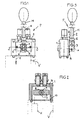
- Fig. 1 Dashed lines illustrates a hydraulic slide valve V with at least one linearly adjustable and definable in each adjustment slide piston K or other linearly adjustable valve element.
- a positioning device P with a lever operation for the respective spool K mounted.
- the spool K is linearly adjusted when a hand lever H is moved about a pivot axis X.
- the hand lever H is mounted on a lever housing 1 which is mounted on the valve housing of the hydraulic slide valve V and rotatably supports a shaft 4 whose axis coincides with the pivot axis X.
- the hand lever H has, for example, a lever rod 2, which is mounted with a nut 6 in a lever carrier 3, which is fixed on a protruding end of the shaft 4 by means of a notched pin 5 on the outside of the lever housing 1.
- a spool actuator 7 is mounted, here for example a two-armed lever for mutual operation, for example, two spool.
- the spool actuator 7 may also be designed differently, for example so that it is coupled in both adjustment directions of the spool with this.
- the spool K always in contact with the spool actuator 7 remains, for example by spring action or hydraulic loading or the like .
- the spool K therefore makes every movement of the spool actuator 7 and remains detained in the respective adjustment when the spool actuator 7 is fixed about the pivot axis X.
- the inner chamber 9 is sealed for example by a seal 10 to the outside.
- the lever carrier 3 is associated with an outer side 16 of the lever housing 1 and is provided here in the area between the lever carrier 3 and the lever housing 1, at least one hand lever friction brake B, which determines the hand lever H in any position of its range of motion, as long as not an operator the braking resistor or intentionally overcomes the acting braking torque.
- the positioning device P especially in Fig. 3 , equipped with a ball lock R, which makes it possible to lock the hand lever H and thus the spool K in at least one selected position in addition to the action of the hand lever friction brake B, such that an operator despite the braking feels on the hand lever H, if this selected position has been set.
- the positioning device P will be described in detail Fig. 4 explained.
- the shaft 4 passing through the lever housing 1 projects with both ends beyond the outer sides 15, 16 of the lever housing 1 facing away from one another, and is in bores of the lever housing 1, for example sealed by O-rings 11 rotatable.
- a sleeve 12 is mounted, which is supported against the outer side 15.
- the sleeve 12 may be detachably fixed by means of a snap ring 13 in a groove 14 on the shaft 4.
- the sleeve 12 transmits an acting in the direction of the pivot axis X bias for a brake element E of the hand lever friction brake B on the outer side 15 of the lever housing. 1
- the brake element E of the hand lever friction brake B is in the embodiment shown a disc spring 19 or a package of series-connected disc springs 19, inserted into a seat 18 in the lever carrier 3.
- the seat 18 is for example a conical recess.
- Each disc spring 19 surrounds the shaft 4.
- the plate spring 19 facing the outer side 16 of the lever housing 1 bears against a braking surface 17, which is formed either directly from the outer side 16 or provided in this.
- lever carrier 3 mounted on the shaft 4 is positioned over the sleeve 12 relative to the outside 16 of the lever housing 1 so that the braking element E is biased and, provided that the braking surface 17 is flat, generates a uniform braking torque about the pivot axis X, that determines the hand lever H in the respective position via the lever carrier 3, and in the sequence via the spool actuator 7 and the associated spool K.
- disc springs 19 instead of one or more disc springs 19, it would also be possible to use corrugated rings, ring springs, or other spring elements, or plastic springs, possibly even with an annular brake body (not shown).
- the sleeve 12 or a technically equivalent stop could be fixed by a screw, for example, such that the bias for the brake element E is adjustable or adjustable to change the braking torque.
- the optionally additionally provided ball lock R is provided in the embodiment shown concentrically to the pivot axis X and radially outside of the hand lever friction brake B.
- a detent ball 20 is arranged axially displaceably, which is pressed by a spring 23 in a provided in the outer side 16 latching recess 21.
- the spring 23 is supported for example by a screw 24 in the lever carrier 3.
- the ball latch R is engaged. If the hand lever H from the in Fig. 4 shown position moves about the pivot axis X, then exits the at least one detent ball 20 from the locking recess 21 and rolls on the flat outer side 16, while the hand lever friction brake B continues to operate with its adjusted braking torque.
- not shown embodiment could be arranged at both ends of the shaft 4 and outside the lever housing 1 hand lever friction brakes B, acting in the direction of the pivot axis X bias cancel or compensate each other. Furthermore, at least the hand lever friction brake B and / or the ball latch R could be accommodated in the inner chamber 9 of the lever housing 1.
- the spool K could additionally be linearly adjusted in other ways than by hand without using the hand lever H, for example by means of magnets, a hydraulic precontrol or the like.
Abstract
Description
Die Erfindung betrifft ein Hydraulik-Schieberventil gemäß Oberbegriff des Patentanspruchs 1.The invention relates to a hydraulic slide valve according to the preamble of
Bei einem aus
Bei dem aus
Bei beiden bekannten Lösungen ist der die Haltekraft erzeugende Teil der Positioniervorrichtung baulich mit dem Schieberkolben vereinigt, damit dieser eine eingestellte Verstellposition nicht mehr selbsttätig verlässt, selbst wenn Strömungskräfte, Druckkräfte oder andere parasitäre Kräfte am Schieberkolben wirken, und solange nicht der Handhebel mit Absicht bewegt wird.In both known solutions of the holding force generating part of the positioning device is structurally associated with the spool so that it no longer automatically leaves a set adjustment position, even if flow forces, pressure forces or others parasitic forces act on the spool, and unless the hand lever is intentionally moved.
In einem im Internet unter www.sauer-danfoss aufrufbaren technischen Informationsblatt (Nr. 520L0344 · Rev FK · Oktober 2009) wird auf eine Reibraste PVMR für Proportional-Schieberventile des Typs PVG 32 hingewiesen. Diese Reibraste ist in einem zusätzlich am Ventilgehäuse dem Handhebel abgewandt montierbaren Gehäuse untergebracht, und enthält einen mit dem Schieberkolben verschraubten Stößel, der durch von außen radial angepresste, einstellbare Kugelverrastungen gehemmt wird, und den Schieberkolben in jeder Verstellposition festlegt.A technical bulletin (No. 520L0344 · Rev. FK · October 2009) available on the Internet at www.sauer-danfoss refers to a PVMR friction button for PVG 32 proportional gate valves. This frictional button is housed in a housing additionally facing away from the hand lever on the valve housing, and contains a plunger bolted to the spool, which is inhibited by externally pressed radially adjustable, adjustable ball detents, and determines the spool in each adjustment position.
Solche Positioniervorrichtungen sind speziell für Geräte zweckmäßig, bei denen eine manuell gewählte Verstellposition des Schieberkolbens so lange unverändert gehalten werden soll, bis eine andere Verstellposition, z.B. mittels des Handhebels, eingestellt wird. Dies ist beispielsweise bei Gesteinsbohrmaschinen der Fall, bei denen ein Arbeiter auch unter schlechten Sichtverhältnissen sicher sein muss, dass sich die gewählte Verstellposition und damit die Arbeitsgeschwindigkeit des Gerätes nicht verändert. Ferner ist es bei solchen Maschinen häufig zweckmäßig, wenn der zumindest mittels des Handhebels verstellbare Schieberkolben in zumindest einer ausgewählten, am Handhebel deutlich spürbaren Verstellposition positionierbar ist, und diese einhält, bis eine neuerliche Verstellung, z.B. am Handhebel, vorgenommen wird.Such positioning devices are particularly suitable for devices in which a manually selected adjustment position of the spool is to be kept unchanged until another adjustment position, e.g. by means of the hand lever, is set. This is the case, for example, with rock drilling machines, in which a worker must be sure, even under poor visibility, that the selected adjustment position and thus the working speed of the device does not change. Furthermore, it is often expedient in such machines, if the adjustable at least by means of the hand lever spool is positionable in at least one selected, clearly perceptible to the hand lever adjustment position, and this complies with until a further adjustment, e.g. on the hand lever, is made.
Bei einer aus
Bei einer aus
Bei einer aus
Der Erfindung liegt die Aufgabe zugrunde, ein Hydraulik-Schieberventil der eingangs genannten Art dahingehend zu verbessern, dass beliebige Verstellpositionen eines zumindest manuell verstellbaren Schieberkolbens auf baulich einfache und kostengünstige Weise haltbar sind.The invention has for its object to improve a hydraulic slide valve of the type mentioned in that any adjustment of an at least manually adjustable spool are structurally simple and inexpensive way preserved.
Die gestellte Aufgabe wird mit den Merkmalen des Patentanspruchs 1 gelöst.The stated object is achieved with the features of
Bei dem Hydraulik-Schieberventil wird in Abkehr vom bekannten Prinzip, den Schieberkolben direkt zu hemmen, der Handhebel durch die Handhebel-Reibungsbremse mit einem gleichförmigen Bremsmoment beaufschlagt, das der Benutzer überwinden muss, um den Schieberkolben in eine neue Verstellposition zu bringen. Die Kopplung zwischen dem Handhebel und dem Schieberkolben ist so gestaltet, dass der Schieberkolben entweder stets der Handhebel-Bewegung folgt, z.B. durch Federbeaufschlagung oder hydraulische Beaufschlagung, oder mit dem Handhebel in beiden Verstellrichtungen gekoppelt ist, so dass der gebremste, nicht betätigte Handhebel den Schieberkolben festhält. Die Handhebel-Reibungsbremse ist baulich einfach und platzsparend in dem Bereich unterbringbar, in welchem der Handhebel am Ventilgehäuse montiert wird. Somit bleibt am Ventilgehäuse zusätzlicher Bauraum für andere Ausstattungskomponenten frei. Das Bremsmoment für den Handhebel kann nach Bedarf eingestellt werden, und entweder kontinuierlich wirken, oder mit spürbaren Rasten, oder kann in der einen oder anderen Bewegungsrichtung des Handhebels zu- oder abnehmen. Die Handhebel-Reibungsbremse ist funktionssicher, hat keinen nennenswerten Verschleiß, und wirkt weitestgehend unabhängig von Temperatur- und Erschütterungseinflüssen. Der Handhebel wird so gehemmt, dass er durch Erschütterungen oder vom Schieberkolben zurückwirkende Kräfte nicht selbsttätig bewegt wird, ist jedoch von Hand mit nur vertretbarem Kraftaufwand verstellbar. Da es bei Hydraulik-Schieberventilen zweckmäßig ist, zumindest eine ausgewählte Verstellposition vorzusehen, beispielsweise entsprechend der Nullstellung, deren Erreichen beim Bewegen des Handhebels deutlich spürbar sein soll, ist zur zusätzlichen Positionierung des Schieberkolbens in der wenigstens einen ausgewählten Verstellposition der Handhebel-Reibungsbremse funktionell eine Kugelverrastung zugeordnet. Die Kugelverrastung ist baulich mit der Handhebel-Reibungsbremse kombiniert und wirkt zwischen dem Handhebel und dem Hebelgehäuse. Die zusätzliche Positionieraufgabe der Kugelverrastung wird somit ohne Beanspruchung nennenswerten Bauraums realisiert, und derart, dass die Kugelverrastung und die Handhebel-Reibungsbremse ohne gegenseitige Beeinflussung zusammenarbeiten. Der Handhebel ist in einem am Ventilgehäuse angeordneten Hebelgehäuse vorgesehen und mit dem Schieberkolben gekoppelt. Die Handhebel-Reibungsbremse weist als Bremselement wenigstens ein Federelement auf. Als Bremselement kann eine Tellerfeder oder Tellerfeder-Paket vorgesehen sein, oder andere Federelemente wie Wellfedern, Ringfedern, Kunststofffedern, oder andere Federn. Das Bremselement ist in Richtung der Schwenkachse gegen eine Bremsfläche vorgespannt und erzeugt in Zusammenwirkung mit der Bremsfläche ohne zusätzliche Bauteile sowohl die Vorspannung als auch das Bremselement.In the hydraulic slide valve, in departure from the known principle to inhibit the spool directly, the hand lever is acted upon by the hand lever friction brake with a uniform braking torque, which must overcome the user to bring the spool to a new adjustment position. The coupling between the hand lever and the spool is designed so that the spool either always follows the hand lever movement, eg by spring action or hydraulic Actuation, or is coupled to the hand lever in both adjustment directions, so that the braked, not actuated hand lever holds the spool. The hand lever friction brake is structurally simple and space-saving housable in the area in which the hand lever is mounted on the valve body. Thus, additional space for other equipment components remains free at the valve housing. The braking torque for the hand lever can be adjusted as needed, and either act continuously, or with noticeable detents, or can in one or the other direction of movement of the hand lever or increase. The hand lever friction brake is functionally reliable, has no significant wear, and acts largely independent of temperature and vibration influences. The hand lever is inhibited so that it is not moved automatically by shaking or by the spool back forces, but is adjustable by hand with only reasonable effort. Since it is expedient for hydraulic slide valves, at least to provide a selected adjustment position, for example according to the zero position, the achievement of which should be clearly felt when moving the hand lever, for additional positioning of the spool in the at least one selected adjustment of the hand lever friction brake functionally a ball lock assigned. The ball lock is structurally combined with the hand lever friction brake and acts between the hand lever and the lever housing. The additional positioning of the ball latch is thus realized without stress appreciable space, and such that the ball latch and the hand lever friction brake work together without mutual interference. The hand lever is provided in a valve housing arranged on the lever housing and coupled to the spool. The hand lever friction brake has at least one spring element as a brake element. As a brake element may be provided a plate spring or disc spring package, or other spring elements such as corrugated springs, ring springs, plastic springs, or other springs. The braking element is biased in the direction of the pivot axis against a braking surface and generates in cooperation with the braking surface without additional components, both the bias voltage and the braking element.
Zweckmäßig ist die baulich mit der Handhebel-Reibungsbremse kombinierte Kugelverrastung zur Schwenkachse konzentrisch und radial innerhalb und/oder außerhalb der Handhebel-Reibungsbremse angeordnet.Suitably, the combined with the hand lever friction brake ball latch to the pivot axis is arranged concentrically and radially inside and / or outside of the hand lever friction brake.
Der Handhebel ist mit der Schieberkolben über zumindest eine im Hebelgehäuse um die Schwenkachse verdrehbar gelagerte Welle gekoppelt, wobei die Handhebel-Reibungsbremse und die Kugelverrastung funktionell zwischen dem Hebelgehäuse und der Welle angeordnet sind. Eine Tellerfeder oder ein Tellerfeder-Paket als das Bremselement, in dem die Tellerfedern in Serie geschaltet sind, erzeugt eine sehr hohe und permanente Bremskraft, die sich außerdem sehr präzise einstellen lässt und verschleißunabhängig über lange Standzeiten wirksam bleibt. Die aus der Vorspannung des Bremselements resultierende Gegenkraft wird von der Welle am Hebelgehäuse abgestützt. Alternativ kann die Vorspannkraft auch auf andere Weise aufgenommen werden, ohne die Welle zu belasten.The hand lever is coupled to the spool via at least one rotatably mounted in the lever housing about the pivot axis mounted shaft, wherein the hand lever friction brake and the ball latching are arranged functionally between the lever housing and the shaft. A plate spring or a plate spring package as the brake element in which the disc springs are connected in series, generates a very high and permanent braking force, which also can be set very precisely and wear-independent remains effective over long periods. The resulting from the bias of the braking element counterforce is supported by the shaft on the lever housing. Alternatively, the biasing force can be absorbed in other ways, without burdening the shaft.
In dem Hebelgehäuse kann eine nach außen abdichtbare Innenkammer vorgesehen sein, in der auf der Welle ein Schieberkolben-Betätiger angeordnet ist. Die Handhebel-Reibungsbremse und die Kugelverrastung sind an der Außenseite des Hebelgehäuses angeordnet, d. h. zweckmäßig außerhalb eines Bereiches, in dem Hydraulikmedium eindringt und/oder zumindest ein bestimmter Druck herrscht. Das Hebelgehäuse mit dem Handhebel und der Handhebel-Reibungsbremse zuzüglich der Kugelverrastung können eine vorfertigbare Baueinheit bilden, die zu unterschiedlichen Ventiltypen passt oder an solche einfach anpassbar ist. Mit der Baueinheit kann auch eine nachträgliche Umrüstung eines Hydraulik-Schieberventils vorgenommen werden.In the lever housing, an outwardly sealable inner chamber may be provided, in which a spool actuator is arranged on the shaft. The hand lever friction brake and the ball latch are located on the outside of the lever housing, i. H. expedient outside of an area in which hydraulic medium penetrates and / or at least a certain pressure prevails. The lever housing with the hand lever and the hand lever friction brake plus the ball lock can form a prefabricated unit that fits different valve types or is easily adaptable to such. With the unit can also be made a subsequent conversion of a hydraulic slide valve.
Zweckmäßig ist das Bremselement auf der Welle in eine Fassung eines Hebelträgers eingesetzt. Dies ist beispielsweise ein konisch vertiefter Sitz, so dass vom Bremselement in Richtung der Schwenkachse des Handhebels möglichst wenig Bauraum beansprucht wird.Suitably, the brake element is inserted on the shaft in a socket of a lever carrier. This is, for example, a conically recessed seat, so that the brake element in the direction of the pivot axis of the hand lever takes up as little space as possible.
Zweckmäßig wird dabei die Welle entgegen der Vorspannung, mit der das Bremselement in Richtung der Schwenkachse gegen die Bremsfläche beispielsweise am Hebelgehäuse angepresst wird, gegenüber dem Hebelgehäuse abgestützt. Diese Lösung ist baulich einfach und funktionssicher, weil die Welle in ihrer Drehbewegung gebremst wird und gleichzeitig die Vorspannung überträgt. Das Bremselement könnte alternativ am Hebelgehäuse (z. B. versenkt) angeordnet sein und mit einer Bremsfläche am Hebelträger zusammenwirken.Appropriately, while the shaft against the bias, with which the brake element is pressed in the direction of the pivot axis against the braking surface, for example, on the lever housing, supported relative to the lever housing. This solution is structurally simple and reliable, because the shaft is braked in its rotational movement and at the same time transmits the bias voltage. Alternatively, the brake element could be arranged on the lever housing (for example recessed) and interact with a braking surface on the lever carrier.
Bei einer zweckmäßigen Ausführungsform ist auf einem aus dem Hebelgehäuse vorstehenden Ende der Welle eine sich am Hebelgehäuse abstützende Hülse montiert. Die Hülse kann mittels eines Sprengrings abnehmbar auf der Welle festgelegt sein, oder durch eine Schraubverbindung oder eine Madenschraube, oder dgl. Dies erleichtert die Montage und Demontage der Positioniervorrichtung des Hydraulik-Schieberventils. Eine Schraubverbindung erlaubt das Verändern der Vorspannung. Alternativ könnte die Handhebel-Reibungsbremse sogar im Inneren des Hebelgehäuses untergebracht werden.In an expedient embodiment, a sleeve supported on the lever housing is mounted on an end of the shaft protruding from the lever housing. The sleeve can be removably fixed by means of a snap ring on the shaft, or by a screw or a grub screw, or the like. This facilitates the assembly and Disassembly of the positioning of the hydraulic slide valve. A screw connection allows changing the bias voltage. Alternatively, the hand lever friction brake could even be housed inside the lever housing.
Eine baulich einfache Ausführungsform der Kugelverrastung weist einen Hebelträger radial außerhalb der Handhebel-Reibungsbremse wenigstens eine federbelastete Rastkugel und wenigstens eine in der Außenseite des Hebelgehäuses angeordnete Rastvertiefung auf. Die Kugelverrastung könnte aber auch im Inneren des Hebelgehäuses und dort zwischen der Welle und dem Hebelgehäuse platziert werden. Die Unterbringung im Hebelträger und an der Außenseite des Hebelgehäuses ist herstellungs- und montagetechnisch gegebenenfalls günstiger.A structurally simple embodiment of the ball latch has a lever carrier radially outside the hand lever friction brake at least one spring-loaded detent ball and at least one arranged in the outer side of the lever housing latching recess. But the ball lock could also be placed inside the lever housing and there between the shaft and the lever housing. The accommodation in the lever carrier and on the outside of the lever housing manufacturing and assembly technology may be cheaper.
Schließlich sind zwecks einfacher Montage und Demontage der Hebelträger und ein in einer Innenkammer des Hebelgehäuses angeordneter Schieberkolben-Betätiger jeweils mit einem Kerbstift an der Welle montiert.Finally, for ease of assembly and disassembly, the lever carrier and a spool actuator disposed in an inner chamber of the lever housing are each mounted with a grooved pin on the shaft.
Die Positioniervorrichtung, die als eine vorfertigbare Baueinheit an verschiedenen Hydraulik-Schieberventil-Typen montiert werden kann, ist so ausgelegt, dass der Handhebel mit einem Hebelträger auf einer in einem Hebelgehäuse drehgelagerten Welle montiert ist. Die Handhebel-Reibungsbremse ist auf der Welle und funktionell zwischen dem Hebelträger und dem Hebelgehäuse angeordnet. In diesem Bereich ist auch die Kugelverrastung untergebracht.The positioning device, which can be mounted as a prefabricatable assembly on various hydraulic spool valve types, is designed so that the hand lever is mounted with a lever carrier on a rotatably mounted in a lever housing shaft. The hand lever friction brake is disposed on the shaft and functionally between the lever carrier and the lever housing. In this area, the ball lock is housed.
Die beiden Aufgaben, das Bremsmoment zu erzeugen und die Vorspannkraft für das Bremsmoment abzustützen, werden zweckmäßig so gelöst, dass die Hülse und das Bremselement in Bezug auf die Schwenkachse an voneinander abgewandten Außenseiten des Hebelgehäuses angeordnet sind. Dies bietet auch Vorteile dahingehend, dass gegebenenfalls das Hebelgehäuse eine Druckmittel enthaltende und/oder unter Druck setzbare Innenkammer besitzt und kein Druckmittel zur Handhebel-Reibungsbremse gelangen sollte. Alternativ könnte die Handhebel-Reibungsbremse jedoch sogar im Inneren des Hebelgehäuses untergebracht werden, wo dann auch die Vorspannung abgestützt werden kann, beispielsweise, falls der Innenraum des Hebelgehäuses kein Hydraulikdruckmittel enthält.The two tasks to generate the braking torque and to support the biasing force for the braking torque, are advantageously solved so that the sleeve and the brake element are arranged with respect to the pivot axis on opposite outer sides of the lever housing. This also offers advantages in that, if appropriate, the lever housing has a pressure medium-containing and / or pressurizable inner chamber and no pressure medium should reach the hand lever friction brake. Alternatively, however, the hand lever friction brake could be accommodated even inside the lever housing, where then the bias voltage can be supported, for example, if the interior of the lever housing contains no hydraulic pressure medium.
Anhand der Zeichnungen wird eine Ausführungsform des Erfindungsgegenstandes erläutert. Es zeigen:
- Fig. 1
- eine Seitenansicht eines Hydraulik-Schieberventils mit einer Handhebel- Betätigung, teilweise im Schnitt,
- Fig. 2
- eine Schnittdarstellung in der gleichen Blickrichtung wie in
Fig. 1 des Hydrau- lik-Schieberventils mit einer montierten Positioniervorrichtung, - Fig. 3
- eine um 90° gegenüber
Fig. 1 gedrehte Ansicht nur der Positioniervorrichtung, und - Fig. 4
- einen Schnitt in der Ebene IV- IV in
Fig. 1 , und in vergrößertem Maßstab der Positioniervorrichtung.
- Fig. 1
- a side view of a hydraulic slide valve with a lever operation, partially in section,
- Fig. 2
- a sectional view in the same direction as in
Fig. 1 the hydraulic spool valve with a mounted positioning device, - Fig. 3
- a 90 ° opposite
Fig. 1 rotated view of the positioning device only, and - Fig. 4
- a section in the plane IV-IV in
Fig. 1 , and on an enlarged scale of the positioning device.
In der zugehörigen Schnittansicht von
Gemäß
Optional ist die Positioniervorrichtung P, speziell in
Die Positioniervorrichtung P wird im Detail anhand
Das Bremselement E der Handhebel-Reibungsbremse B ist in der gezeigten Ausführungsform eine Tellerfeder 19 bzw. ein Paket aus in Serie geschalteten Tellerfedern 19, eingesetzt in einen Sitz 18 im Hebelträger 3. Der Sitz 18 ist beispielsweise eine konische Vertiefung. Jede Tellerfeder 19 umgibt die Welle 4. Die der Außenseite 16 des Hebelgehäuses 1 zugewandte Tellerfeder 19 liegt an einer Bremsfläche 17 an, die entweder direkt von der Außenseite 16 gebildet oder in dieser vorgesehen ist. Der mittels des Kerbstiftes 5 (
Anstelle einer oder mehrerer Tellerfedern 19 könnten auch Wellringe, Ringfedern, oder andere Federelemente, oder Kunststofffedern, gegebenenfalls sogar mit einem ringförmigen Bremskörper (nicht gezeigt) verwendet werden. Alternativ könnte die Hülse 12 oder ein technisch gleichwertiger Anschlag durch eine Schraubverbindung festgelegt sein, beispielsweise derart, dass die Vorspannung für das Bremselement E einstellbar oder verstellbar ist, um das Bremsmoment zu verändern.Instead of one or more disc springs 19, it would also be possible to use corrugated rings, ring springs, or other spring elements, or plastic springs, possibly even with an annular brake body (not shown). Alternatively, the
Die optional zusätzlich vorgesehene Kugelverrastung R ist bei der gezeigten Ausführungsform konzentrisch zur Schwenkachse X und radial außerhalb der Handhebel-Reibungsbremse B vorgesehen. In zumindest einer Vertiefung 22 des Hebelträgers 3 ist eine Rastkugel 20 axial verschieblich angeordnet, die durch eine Feder 23 in eine in der Außenseite 16 vorgesehene Rastvertiefung 21 gedrückt wird. Die Feder 23 wird beispielsweise durch eine Schraube 24 im Hebelträger 3 abgestützt. In der in
Bei einer alternativen, nicht gezeigten Ausführungsform könnten an beiden Enden der Welle 4 und außerhalb des Hebelgehäuses 1 Handhebel-Reibungsbremsen B angeordnet sein, deren in Richtung der Schwenkachse X wirkende Vorspannungen einander aufheben oder ausgleichen. Ferner könnte zumindest die Handhebel-Reibungsbremse B und/oder die Kugelverrastung R in der Innenkammer 9 des Hebelgehäuses 1 untergebracht sein. Obwohl dies nicht gezeigt ist, könnte der Schieberkolben K zusätzlich auch auf andere Weise als von Hand linear verstellt werden, ohne den Handhebel H zu benutzen, beispielsweise durch Magneten, eine Hydraulikvorsteuerung oder dgl..In an alternative, not shown embodiment could be arranged at both ends of the
Claims (9)
- Hydraulic slider valve (V), comprising at least one slider piston (K) being linearly adjustable within a valve housing at least manually by means of a hand lever (H) which is movable about a pivot axis (K) and is coupled with the slider piston (K), and a force-fit positioning device (P) for securing the slider piston (K) in each adjustment position via a friction brake, wherein the hand lever (A) is arranged at a lever housing (1) provided at the valve housing, characterised in that the friction brake is a hand lever friction brake (B) and is arranged between the hand lever (H) and the lever housing (1), that the hand lever friction brake (B) is braking with a braking torque in each adjustment position of the slider piston (K) and fixes the hand lever (H) in relation to the lever housing (1) against arbitrary movements about the lever axis (X) at least in case of a force acting backwards from the slider piston (K), that the hand lever friction brake (B) comprises as a braking element (E) at least one spring element which is preloaded in the direction of the pivot axis (X) against a braking surface (17), and that for additionally positioning the slider piston (K) in at least one selected adjustment position a ball ratcheting mechanism (R) is functionally associated to the hand lever friction brake (B) and is arranged between the hand lever (H) and the lever housing (1).
- Hydraulic slider valve according to claim 1, characterised in that the ball ratcheting mechanism (R) is concentric to the pivot axis (X) and is arranged radially inwards and/or outwards of the hand lever friction brake (B).
- Hydraulic slider valve according to claim 1, characterised in that hand lever (H) is coupled with the slider piston (K) via a shaft (4) which is supported for rotation about the pivot axis (X) in the lever housing (1), and that the hand lever friction brake (B) and the ball ratcheting mechanism (R) are arranged functionally between the lever housing (1) and the shaft (4).
- Hydraulic slider valve according to claim 3, characterised in that the hand lever friction brake (B) has at least one plate spring (19) as the braking element (E), preferably a package of plate springs, that the braking surface (19) is arranged exteriorly at the lever housing (1), and that a counter force resulting from the preload of the braking element (E) is backed-up by the shaft (4) at the lever housing (1).
- Hydraulic slider valve according to claim 3, characterised in that the lever housing (1) comprises an interior chamber (9) which is sealed to the exterior, and that a slider piston actuator (7) is arranged in the interior chamber (9) on the shaft (4).
- Hydraulic slider valve according to claim 3, characterised in that the braking element (E) is inserted on the shaft (4) into a socket (18), preferably into a conically depressed seat, of a lever carrier (3).
- Hydraulic slider valve according to claim 4, characterised in that on an end of the shaft (4) protruding out of the lever housing (1) a collar (12) is mounted which abuts at the lever housing (1), and that the collar (12) is mounted, preferably, by means of a spring ring (13) or a threaded connection.
- Hydraulic slider valve according to claim 1, characterised in that the ball ratcheting mechanism (R) comprises at least one spring loaded ball (20) in a lever carrier (3) radially outside of the hand lever friction brake (B) and at least one depression formed in the outer side (16) of the lever housing (1).
- Hydraulic slider valve according to at least one of the preceding claims, characterised in that the lever carrier (3) and the slider piston actuator (7) arranged in the interior chamber (9) of the lever housing (1) are mounted in the shaft (4) with grooved dowel pins (5, 8).
Priority Applications (2)
| Application Number | Priority Date | Filing Date | Title |
|---|---|---|---|
| AT09015383T ATE545815T1 (en) | 2009-12-11 | 2009-12-11 | HYDRAULIC SLIDE VALVE WITH POSITIONING DEVICE |
| EP09015383A EP2333390B1 (en) | 2009-12-11 | 2009-12-11 | Hydraulic gate valve with positioning device |
Applications Claiming Priority (1)
| Application Number | Priority Date | Filing Date | Title |
|---|---|---|---|
| EP09015383A EP2333390B1 (en) | 2009-12-11 | 2009-12-11 | Hydraulic gate valve with positioning device |
Publications (2)
| Publication Number | Publication Date |
|---|---|
| EP2333390A1 EP2333390A1 (en) | 2011-06-15 |
| EP2333390B1 true EP2333390B1 (en) | 2012-02-15 |
Family
ID=41666387
Family Applications (1)
| Application Number | Title | Priority Date | Filing Date |
|---|---|---|---|
| EP09015383A Active EP2333390B1 (en) | 2009-12-11 | 2009-12-11 | Hydraulic gate valve with positioning device |
Country Status (2)
| Country | Link |
|---|---|
| EP (1) | EP2333390B1 (en) |
| AT (1) | ATE545815T1 (en) |
Families Citing this family (1)
| Publication number | Priority date | Publication date | Assignee | Title |
|---|---|---|---|---|
| EP3088782B1 (en) * | 2015-04-29 | 2019-09-18 | HAWE Hydraulik SE | Hydraulic control valve in gate construction and mobile hydraulics with associated control valve |
Family Cites Families (5)
| Publication number | Priority date | Publication date | Assignee | Title |
|---|---|---|---|---|
| US3602245A (en) | 1970-02-26 | 1971-08-31 | Abex Corp | Universal detent positioner |
| US4543851A (en) | 1982-06-23 | 1985-10-01 | Acf Industries, Incorporated | Torque application assembly for closure valve of a railroad hopper car outlet |
| DE3432736A1 (en) | 1984-05-05 | 1985-11-14 | Losenhausen Maschinenbau AG & Co KG, 4000 Düsseldorf | Adjusting device held by frictional engagement |
| US4949591A (en) | 1988-04-15 | 1990-08-21 | Capro, Inc. | Lever control |
| DE20212458U1 (en) | 2002-08-13 | 2003-12-24 | Hawe Hydraulik Gmbh & Co. Kg | Locking device and hydraulic slide valve |
-
2009
- 2009-12-11 AT AT09015383T patent/ATE545815T1/en active
- 2009-12-11 EP EP09015383A patent/EP2333390B1/en active Active
Also Published As
| Publication number | Publication date |
|---|---|
| EP2333390A1 (en) | 2011-06-15 |
| ATE545815T1 (en) | 2012-03-15 |
Similar Documents
| Publication | Publication Date | Title |
|---|---|---|
| EP0452702B1 (en) | Fixing device for a linear-movement unit | |
| EP3084277B1 (en) | Hydraulic valve device | |
| DE2608502B2 (en) | Release device for the interruption and automatic return of the operating function of a spring-loaded brake cylinder | |
| EP1917458A1 (en) | Linear actuating organ, in particular for the remote actuation of displaceable components in wind tunnel models | |
| DE102015202916A1 (en) | Coupling device with lever operation | |
| DE19907483C2 (en) | Adjustment device acting on both sides | |
| EP2333390B1 (en) | Hydraulic gate valve with positioning device | |
| EP0208827A1 (en) | Gripper | |
| DE112013007620T5 (en) | Valve operating arrangement with friction means and biasing element | |
| DE4125706C1 (en) | ||
| EP0829407B1 (en) | Piston / cylinder arrangement | |
| DE2707124C2 (en) | Manual adjustment device for the brake lining wear of a mechanically operated floating caliper disc brake | |
| DE202008016454U1 (en) | Tool for polishing and fine grinding of optically effective surfaces in fine optics | |
| EP1328738A1 (en) | Device for releasing a gas spring | |
| DE1751931A1 (en) | Double acting, pressure medium controlled cylinder | |
| DE102016015728A1 (en) | Parking brake actuator | |
| EP1618312B1 (en) | Bilateral drive | |
| EP3298312B1 (en) | Roller lever actuating device, and roller lever valve arrangement equipped therewith | |
| DE102019110910A1 (en) | Door arrester | |
| DE102005005136A1 (en) | Swivel device for work-piece clamping unit, comprising operating shaft with recesses and spring supported locking bolt | |
| DE19750614C2 (en) | Device for changing the displacement volume of a hydrostatic machine | |
| DE2905799C2 (en) | Pneumatic positioner with spiral measuring spring | |
| CH663992A5 (en) | CONTROL CARTRIDGE. | |
| DE102016107003A1 (en) | Parking brake actuator | |
| DE2404320C2 (en) |
Legal Events
| Date | Code | Title | Description |
|---|---|---|---|
| PUAI | Public reference made under article 153(3) epc to a published international application that has entered the european phase |
Free format text: ORIGINAL CODE: 0009012 |
|
| 17P | Request for examination filed |
Effective date: 20100914 |
|
| AK | Designated contracting states |
Kind code of ref document: A1 Designated state(s): AT BE BG CH CY CZ DE DK EE ES FI FR GB GR HR HU IE IS IT LI LT LU LV MC MK MT NL NO PL PT RO SE SI SK SM TR |
|
| AX | Request for extension of the european patent |
Extension state: AL BA RS |
|
| GRAP | Despatch of communication of intention to grant a patent |
Free format text: ORIGINAL CODE: EPIDOSNIGR1 |
|
| RIC1 | Information provided on ipc code assigned before grant |
Ipc: F16K 35/04 20060101AFI20110707BHEP Ipc: G05G 5/16 20060101ALI20110707BHEP Ipc: G05G 5/22 20060101ALI20110707BHEP |
|
| RTI1 | Title (correction) |
Free format text: HYDRAULIC GATE VALVE WITH POSITIONING DEVICE |
|
| GRAS | Grant fee paid |
Free format text: ORIGINAL CODE: EPIDOSNIGR3 |
|
| GRAA | (expected) grant |
Free format text: ORIGINAL CODE: 0009210 |
|
| AK | Designated contracting states |
Kind code of ref document: B1 Designated state(s): AT BE BG CH CY CZ DE DK EE ES FI FR GB GR HR HU IE IS IT LI LT LU LV MC MK MT NL NO PL PT RO SE SI SK SM TR |
|
| REG | Reference to a national code |
Ref country code: GB Ref legal event code: FG4D Free format text: NOT ENGLISH Ref country code: CH Ref legal event code: EP |
|
| REG | Reference to a national code |
Ref country code: IE Ref legal event code: FG4D Free format text: LANGUAGE OF EP DOCUMENT: GERMAN |
|
| REG | Reference to a national code |
Ref country code: AT Ref legal event code: REF Ref document number: 545815 Country of ref document: AT Kind code of ref document: T Effective date: 20120315 |
|
| REG | Reference to a national code |
Ref country code: DE Ref legal event code: R096 Ref document number: 502009002776 Country of ref document: DE Effective date: 20120412 |
|
| REG | Reference to a national code |
Ref country code: NL Ref legal event code: VDEP Effective date: 20120215 |
|
| LTIE | Lt: invalidation of european patent or patent extension |
Effective date: 20120215 |
|
| PG25 | Lapsed in a contracting state [announced via postgrant information from national office to epo] |
Ref country code: HR Free format text: LAPSE BECAUSE OF FAILURE TO SUBMIT A TRANSLATION OF THE DESCRIPTION OR TO PAY THE FEE WITHIN THE PRESCRIBED TIME-LIMIT Effective date: 20120215 Ref country code: NO Free format text: LAPSE BECAUSE OF FAILURE TO SUBMIT A TRANSLATION OF THE DESCRIPTION OR TO PAY THE FEE WITHIN THE PRESCRIBED TIME-LIMIT Effective date: 20120515 Ref country code: IS Free format text: LAPSE BECAUSE OF FAILURE TO SUBMIT A TRANSLATION OF THE DESCRIPTION OR TO PAY THE FEE WITHIN THE PRESCRIBED TIME-LIMIT Effective date: 20120615 Ref country code: NL Free format text: LAPSE BECAUSE OF FAILURE TO SUBMIT A TRANSLATION OF THE DESCRIPTION OR TO PAY THE FEE WITHIN THE PRESCRIBED TIME-LIMIT Effective date: 20120215 Ref country code: LT Free format text: LAPSE BECAUSE OF FAILURE TO SUBMIT A TRANSLATION OF THE DESCRIPTION OR TO PAY THE FEE WITHIN THE PRESCRIBED TIME-LIMIT Effective date: 20120215 |
|
| PG25 | Lapsed in a contracting state [announced via postgrant information from national office to epo] |
Ref country code: PL Free format text: LAPSE BECAUSE OF FAILURE TO SUBMIT A TRANSLATION OF THE DESCRIPTION OR TO PAY THE FEE WITHIN THE PRESCRIBED TIME-LIMIT Effective date: 20120215 Ref country code: FI Free format text: LAPSE BECAUSE OF FAILURE TO SUBMIT A TRANSLATION OF THE DESCRIPTION OR TO PAY THE FEE WITHIN THE PRESCRIBED TIME-LIMIT Effective date: 20120215 Ref country code: LV Free format text: LAPSE BECAUSE OF FAILURE TO SUBMIT A TRANSLATION OF THE DESCRIPTION OR TO PAY THE FEE WITHIN THE PRESCRIBED TIME-LIMIT Effective date: 20120215 Ref country code: GR Free format text: LAPSE BECAUSE OF FAILURE TO SUBMIT A TRANSLATION OF THE DESCRIPTION OR TO PAY THE FEE WITHIN THE PRESCRIBED TIME-LIMIT Effective date: 20120516 Ref country code: PT Free format text: LAPSE BECAUSE OF FAILURE TO SUBMIT A TRANSLATION OF THE DESCRIPTION OR TO PAY THE FEE WITHIN THE PRESCRIBED TIME-LIMIT Effective date: 20120615 |
|
| REG | Reference to a national code |
Ref country code: IE Ref legal event code: FD4D |
|
| PG25 | Lapsed in a contracting state [announced via postgrant information from national office to epo] |
Ref country code: CY Free format text: LAPSE BECAUSE OF FAILURE TO SUBMIT A TRANSLATION OF THE DESCRIPTION OR TO PAY THE FEE WITHIN THE PRESCRIBED TIME-LIMIT Effective date: 20120215 |
|
| PG25 | Lapsed in a contracting state [announced via postgrant information from national office to epo] |
Ref country code: SE Free format text: LAPSE BECAUSE OF FAILURE TO SUBMIT A TRANSLATION OF THE DESCRIPTION OR TO PAY THE FEE WITHIN THE PRESCRIBED TIME-LIMIT Effective date: 20120215 Ref country code: RO Free format text: LAPSE BECAUSE OF FAILURE TO SUBMIT A TRANSLATION OF THE DESCRIPTION OR TO PAY THE FEE WITHIN THE PRESCRIBED TIME-LIMIT Effective date: 20120215 Ref country code: DK Free format text: LAPSE BECAUSE OF FAILURE TO SUBMIT A TRANSLATION OF THE DESCRIPTION OR TO PAY THE FEE WITHIN THE PRESCRIBED TIME-LIMIT Effective date: 20120215 Ref country code: CZ Free format text: LAPSE BECAUSE OF FAILURE TO SUBMIT A TRANSLATION OF THE DESCRIPTION OR TO PAY THE FEE WITHIN THE PRESCRIBED TIME-LIMIT Effective date: 20120215 Ref country code: IE Free format text: LAPSE BECAUSE OF FAILURE TO SUBMIT A TRANSLATION OF THE DESCRIPTION OR TO PAY THE FEE WITHIN THE PRESCRIBED TIME-LIMIT Effective date: 20120215 Ref country code: SI Free format text: LAPSE BECAUSE OF FAILURE TO SUBMIT A TRANSLATION OF THE DESCRIPTION OR TO PAY THE FEE WITHIN THE PRESCRIBED TIME-LIMIT Effective date: 20120215 Ref country code: EE Free format text: LAPSE BECAUSE OF FAILURE TO SUBMIT A TRANSLATION OF THE DESCRIPTION OR TO PAY THE FEE WITHIN THE PRESCRIBED TIME-LIMIT Effective date: 20120215 |
|
| PG25 | Lapsed in a contracting state [announced via postgrant information from national office to epo] |
Ref country code: SK Free format text: LAPSE BECAUSE OF FAILURE TO SUBMIT A TRANSLATION OF THE DESCRIPTION OR TO PAY THE FEE WITHIN THE PRESCRIBED TIME-LIMIT Effective date: 20120215 |
|
| PLBE | No opposition filed within time limit |
Free format text: ORIGINAL CODE: 0009261 |
|
| STAA | Information on the status of an ep patent application or granted ep patent |
Free format text: STATUS: NO OPPOSITION FILED WITHIN TIME LIMIT |
|
| 26N | No opposition filed |
Effective date: 20121116 |
|
| REG | Reference to a national code |
Ref country code: DE Ref legal event code: R097 Ref document number: 502009002776 Country of ref document: DE Effective date: 20121116 |
|
| PG25 | Lapsed in a contracting state [announced via postgrant information from national office to epo] |
Ref country code: ES Free format text: LAPSE BECAUSE OF FAILURE TO SUBMIT A TRANSLATION OF THE DESCRIPTION OR TO PAY THE FEE WITHIN THE PRESCRIBED TIME-LIMIT Effective date: 20120526 |
|
| BERE | Be: lapsed |
Owner name: HAWE HYDRAULIK SE Effective date: 20121231 |
|
| PG25 | Lapsed in a contracting state [announced via postgrant information from national office to epo] |
Ref country code: MC Free format text: LAPSE BECAUSE OF NON-PAYMENT OF DUE FEES Effective date: 20121231 Ref country code: BG Free format text: LAPSE BECAUSE OF FAILURE TO SUBMIT A TRANSLATION OF THE DESCRIPTION OR TO PAY THE FEE WITHIN THE PRESCRIBED TIME-LIMIT Effective date: 20120515 |
|
| PG25 | Lapsed in a contracting state [announced via postgrant information from national office to epo] |
Ref country code: BE Free format text: LAPSE BECAUSE OF NON-PAYMENT OF DUE FEES Effective date: 20121231 |
|
| PG25 | Lapsed in a contracting state [announced via postgrant information from national office to epo] |
Ref country code: MT Free format text: LAPSE BECAUSE OF FAILURE TO SUBMIT A TRANSLATION OF THE DESCRIPTION OR TO PAY THE FEE WITHIN THE PRESCRIBED TIME-LIMIT Effective date: 20120215 |
|
| PG25 | Lapsed in a contracting state [announced via postgrant information from national office to epo] |
Ref country code: TR Free format text: LAPSE BECAUSE OF FAILURE TO SUBMIT A TRANSLATION OF THE DESCRIPTION OR TO PAY THE FEE WITHIN THE PRESCRIBED TIME-LIMIT Effective date: 20120215 |
|
| PG25 | Lapsed in a contracting state [announced via postgrant information from national office to epo] |
Ref country code: SM Free format text: LAPSE BECAUSE OF FAILURE TO SUBMIT A TRANSLATION OF THE DESCRIPTION OR TO PAY THE FEE WITHIN THE PRESCRIBED TIME-LIMIT Effective date: 20120215 Ref country code: LU Free format text: LAPSE BECAUSE OF NON-PAYMENT OF DUE FEES Effective date: 20121211 |
|
| PG25 | Lapsed in a contracting state [announced via postgrant information from national office to epo] |
Ref country code: HU Free format text: LAPSE BECAUSE OF FAILURE TO SUBMIT A TRANSLATION OF THE DESCRIPTION OR TO PAY THE FEE WITHIN THE PRESCRIBED TIME-LIMIT Effective date: 20091211 |
|
| REG | Reference to a national code |
Ref country code: CH Ref legal event code: PL |
|
| GBPC | Gb: european patent ceased through non-payment of renewal fee |
Effective date: 20131211 |
|
| PG25 | Lapsed in a contracting state [announced via postgrant information from national office to epo] |
Ref country code: CH Free format text: LAPSE BECAUSE OF NON-PAYMENT OF DUE FEES Effective date: 20131231 Ref country code: LI Free format text: LAPSE BECAUSE OF NON-PAYMENT OF DUE FEES Effective date: 20131231 |
|
| PG25 | Lapsed in a contracting state [announced via postgrant information from national office to epo] |
Ref country code: GB Free format text: LAPSE BECAUSE OF NON-PAYMENT OF DUE FEES Effective date: 20131211 |
|
| PG25 | Lapsed in a contracting state [announced via postgrant information from national office to epo] |
Ref country code: MK Free format text: LAPSE BECAUSE OF FAILURE TO SUBMIT A TRANSLATION OF THE DESCRIPTION OR TO PAY THE FEE WITHIN THE PRESCRIBED TIME-LIMIT Effective date: 20120215 |
|
| REG | Reference to a national code |
Ref country code: FR Ref legal event code: PLFP Year of fee payment: 7 |
|
| REG | Reference to a national code |
Ref country code: AT Ref legal event code: MM01 Ref document number: 545815 Country of ref document: AT Kind code of ref document: T Effective date: 20141211 |
|
| PGFP | Annual fee paid to national office [announced via postgrant information from national office to epo] |
Ref country code: FR Payment date: 20151221 Year of fee payment: 7 |
|
| PGFP | Annual fee paid to national office [announced via postgrant information from national office to epo] |
Ref country code: IT Payment date: 20151230 Year of fee payment: 7 |
|
| PG25 | Lapsed in a contracting state [announced via postgrant information from national office to epo] |
Ref country code: AT Free format text: LAPSE BECAUSE OF NON-PAYMENT OF DUE FEES Effective date: 20141211 |
|
| REG | Reference to a national code |
Ref country code: DE Ref legal event code: R082 Ref document number: 502009002776 Country of ref document: DE Representative=s name: GROSSE, SCHUMACHER, KNAUER, VON HIRSCHHAUSEN, DE |
|
| REG | Reference to a national code |
Ref country code: FR Ref legal event code: ST Effective date: 20170831 |
|
| PG25 | Lapsed in a contracting state [announced via postgrant information from national office to epo] |
Ref country code: IT Free format text: LAPSE BECAUSE OF NON-PAYMENT OF DUE FEES Effective date: 20161211 Ref country code: FR Free format text: LAPSE BECAUSE OF NON-PAYMENT OF DUE FEES Effective date: 20170102 |
|
| REG | Reference to a national code |
Ref country code: DE Ref legal event code: R082 Ref document number: 502009002776 Country of ref document: DE Representative=s name: GROSSE, SCHUMACHER, KNAUER, VON HIRSCHHAUSEN, DE Ref country code: DE Ref legal event code: R081 Ref document number: 502009002776 Country of ref document: DE Owner name: HAWE HYDRAULIK SE, DE Free format text: FORMER OWNER: HAWE HYDRAULIK SE, 81673 MUENCHEN, DE |
|
| P01 | Opt-out of the competence of the unified patent court (upc) registered |
Effective date: 20230523 |
|
| PGFP | Annual fee paid to national office [announced via postgrant information from national office to epo] |
Ref country code: DE Payment date: 20231219 Year of fee payment: 15 |