EP2333357B1 - Bolt for tensioning sections bordering each other - Google Patents
Bolt for tensioning sections bordering each other Download PDFInfo
- Publication number
- EP2333357B1 EP2333357B1 EP09014833A EP09014833A EP2333357B1 EP 2333357 B1 EP2333357 B1 EP 2333357B1 EP 09014833 A EP09014833 A EP 09014833A EP 09014833 A EP09014833 A EP 09014833A EP 2333357 B1 EP2333357 B1 EP 2333357B1
- Authority
- EP
- European Patent Office
- Prior art keywords
- bolt
- threaded spindle
- sliding sleeve
- balls
- openings
- Prior art date
- Legal status (The legal status is an assumption and is not a legal conclusion. Google has not performed a legal analysis and makes no representation as to the accuracy of the status listed.)
- Active
Links
- 238000003780 insertion Methods 0.000 description 3
- 230000037431 insertion Effects 0.000 description 3
- 238000012423 maintenance Methods 0.000 description 3
- 238000003466 welding Methods 0.000 description 3
- 238000005553 drilling Methods 0.000 description 2
- 238000009966 trimming Methods 0.000 description 2
- 238000013459 approach Methods 0.000 description 1
- 230000001419 dependent effect Effects 0.000 description 1
Images


Classifications
-
- F—MECHANICAL ENGINEERING; LIGHTING; HEATING; WEAPONS; BLASTING
- F16—ENGINEERING ELEMENTS AND UNITS; GENERAL MEASURES FOR PRODUCING AND MAINTAINING EFFECTIVE FUNCTIONING OF MACHINES OR INSTALLATIONS; THERMAL INSULATION IN GENERAL
- F16B—DEVICES FOR FASTENING OR SECURING CONSTRUCTIONAL ELEMENTS OR MACHINE PARTS TOGETHER, e.g. NAILS, BOLTS, CIRCLIPS, CLAMPS, CLIPS OR WEDGES; JOINTS OR JOINTING
- F16B21/00—Means for preventing relative axial movement of a pin, spigot, shaft or the like and a member surrounding it; Stud-and-socket releasable fastenings
- F16B21/10—Means for preventing relative axial movement of a pin, spigot, shaft or the like and a member surrounding it; Stud-and-socket releasable fastenings by separate parts
- F16B21/16—Means for preventing relative axial movement of a pin, spigot, shaft or the like and a member surrounding it; Stud-and-socket releasable fastenings by separate parts with grooves or notches in the pin or shaft
- F16B21/165—Means for preventing relative axial movement of a pin, spigot, shaft or the like and a member surrounding it; Stud-and-socket releasable fastenings by separate parts with grooves or notches in the pin or shaft with balls or rollers
Definitions
- the invention relates to a bolt for clamping contiguous parts having openings, comprising a bolt-like part, which is insertable from one side of the abutting parts in the openings, a sliding sleeve, the non-rotatable at one end of the bolt-like part, but in Is longitudinally displaceable and the bolt-like part projects radially outwardly, a threaded spindle which is screwed into the bolt-like part in the longitudinal direction, and at least one clamping element, preferably balls, which are arranged at one end in the interior of the bolt-like part and through at least one opening beyond the outer periphery of the bolt-like part are movable.
- a bolt of the type mentioned above with which two or more contiguous parts of any kind can be braced together.
- Such bolts include a bolt-like part into which a threaded spindle can be screwed from one end face, which protrudes beyond the bolt-like part at this end and at the same time as a hand wheel, usually with an enlarged diameter relative to the bolt-like part is used.
- a sliding sleeve is provided, which is arranged non-rotatably, but displaceable in the longitudinal direction and projects radially beyond the bolt-like part to the outside.
- clamping elements such as balls
- the radial outward movement of these clamping elements is achieved by means of the threaded spindle, which has a conical, frustoconical, in the region of the clamping elements, facing away from the handle end facing the tapered surface.
- To be clamped parts can be the table top or side walls of a trimming and welding table and flat or angular additional parts that can be fixed with the help of such bolts on the table and thus at any point straight and right-angled clamping means with stop surfaces for the welding part to be produced.
- such bolts can be used anywhere where two or more contiguous parts to be clamped together.
- the openings in the adjacent parts may be holes or slots.
- the threaded spindle has an annular groove which serves to receive the balls in the relaxed state. This prevents that the balls can slip completely into the interior of the bolt-like part when the threaded spindle is released, but the threaded spindle can not be completely screwed out for maintenance and / or repair of the bolt. Moreover, it is disadvantageous that the sliding sleeve can be pushed completely dissolved by the bolt-like part when the threaded spindle, which can lead to tilting of the sliding sleeve.
- the DE 91 14 220 U1 describes another bolt for clamping contiguous parts having openings.
- the clamping elements in particular balls with dissolved threaded spindle can slip completely into the interior of the bolt-like part, which can lead to jamming in a renewed tightening of the threaded spindle.
- the invention is based on the problem of further advantageously forming the state of the art.
- a bolt for clamping contiguous parts having openings comprising a bolt-like part insertable into the openings from one side of the abutting parts, a sliding sleeve non-rotatable at one end of the bolt-like part but displaceable longitudinally and the bolt-like part protrudes radially outwards, a threaded spindle which can be screwed into the bolt-like part in the longitudinal direction, and at least one tensioning element, preferably balls, which are arranged at one end in the interior of the bolt-like part and through at least one opening over the outer circumference of the bolt-like part are also movable, the invention proposes that a radial movement possibility of the balls inwardly limiting mandrel is provided and the threaded spindle has at its end a recess for the mandrel.
- the mandrel can advantageously be arranged on a connectable with the bolt-like part, for example screwed, threaded pin.
- the mandrel during assembly of the bolt can be connected from its individual parts after insertion of the balls with the bolt-like part, for example screwed.
- For maintenance and / or repair of the grub screw can be removed again, so that the balls can move completely inward and can be removed from the bolt-like part.
- Fig. 1 is a bolt 1 for clamping adjacent to each other Parts having openings, shown, which is designed in the manner of a locking bolt.
- Fig. 2 to 7 Reference is made, in which individual components of the bolt 1 are shown.
- the bolt 1 comprises a bolt-like part 2 which can be inserted into the openings of abutting parts not shown in the drawing.
- the bolt-like part is penetrated in, an end region of openings 3, in which balls 4 are radially reciprocally movable as clamping elements, due to a flange, not shown, on the outer edge of the openings 3 or other fuse, such as an O-ring, this but can not completely leave.
- a sliding sleeve 5 is non-rotatable, but arranged displaceably in the longitudinal direction of the bolt-like part 2 and projects beyond the bolt-like part radially outwards.
- a bore 6 is provided, which has an internal thread 7 in the upper region.
- a threaded spindle 8 which has a corresponding external thread 9, relative to the bolt-like part 2 screwed.
- the threaded spindle 8 protrudes frontally beyond the bolt-like part 2 and the sliding sleeve 5 and there is widened to a handle 10.
- the handle 10 is rotationally fixed, optionally integrally connected to the threaded spindle 8 and has at its front end a hexagon socket 11 for receiving a corresponding key with lever arm.
- the handle 10 and / or the sliding sleeve 5 can be knurled or non-slip coated to increase the grip.
- the sliding sleeve 5 is in the longitudinal direction relative to the bolt-like part 2 along non-circular, preferably flat sliding surfaces 12 axially displaceable, but due to the ovality of these sliding surfaces 12 rotatably connected to the bolt-like part 2.
- the sliding sleeve 5 preferably has the same outer diameter as the handle 10 and in particular a larger outer diameter than the diameter of the openings in the abutting parts, so that the sliding sleeve 5 rests with its front end 13 on the part to be braced.
- a groove 14 may be provided for receiving an O-ring, not shown in the drawing.
- This O-ring causes the sliding sleeve 5 and thus also the bolt-like part 2 can not turn easily on the part to be braced.
- locking pins 15 are in the sliding surfaces 12 introduced.
- the locking pins 15 cooperate with stops 16, which are arranged on the sliding sleeve 5, and thus form a securing device which secures the sliding sleeve 5 on the bolt-like part 2.
- the threaded spindle 8 ensures the position of the locking pins 15 in the holes of the bolt-like part 2. It is understood that only one locking pin 15 or more locking pins could be provided. Another arrangement of the locking pins 15 outside the sliding surfaces 12 is possible.
- the sliding sleeve 5 can thus be so far on the bolt-like part 2 until the stop 16 of the sliding sleeve 5 is present at the locking pin 15, so that the sliding sleeve 5 can not be completely pushed even with dissolved threaded spindle 8 of the bolt-like part 2. Tilting of the sliding sleeve 5 and thus problems in handling the bolt 1 are thus excluded.
- the end 17 of the threaded spindle 8 has an axial recess 18, in which during clamping a mandrel 19 of an in Fig. 7 shown threaded pin 20 can engage.
- the mandrel 19 serves to limit the radial movement possibility of the balls 4 inwards and does not have to necessarily be connected to a threaded pin 20.
- the threaded pin 20 can be screwed after insertion of the balls with its external thread 21 in an internal thread 22 of the bolt-like part 2, to which a hexagon socket 23 is provided in the threaded pin 20.
- the mandrel 19 can be connected during assembly of the bolt 1 from its individual parts after insertion of the balls 4 with the bolt-like part 2, for example screwed.
- the threaded pin 20 can be removed again, so that the balls 4 can move completely inward and can be removed from the bolt-like part 2.
- the mandrel 19 limits the radial movement possibility of the balls 4 inwards, so that an uncontrolled movement of the balls 4 in the interior of the bolt-like part 2 and thus a possible tilting when tightening the threaded spindle 8 can be avoided.
- a complete screwing of the threaded spindle 8 is ensured in the bolt-like part 2 and thus a maximum possible thickness range during clamping.
- the bolt 1 is tensioned as shown in the 10 and 11 is shown by using the handle 10, the threaded spindle 8 forward, ie in the 10 and 11 screwed to the right against the bolt-like part 2.
- the end 17 of the threaded spindle 8 comes into contact the balls 4 and pushes them radially outward.
- the handle 10 in contact with the sliding sleeve 5 and moves it on the bolt-like part 2 in the direction of the balls 4 until the not shown contiguous parts between the balls 4 and the front end 13 of the sliding sleeve. 5 are tense. With the bolt 1, it is thus possible to clamp together adjacent parts with different overall thicknesses.
Description
Die Erfindung bezieht sich auf einen Bolzen zum Verspannen aneinander liegender Teile, die Öffnungen aufweisen, umfassend ein bolzenartiges Teil, das von einer Seite der aneinander liegenden Teile in die Öffnungen einführbar ist, eine Schiebehülse, die an einem Ende des bolzenartigen Teils unverdrehbar, jedoch in Längsrichtung verschiebbar angeordnet ist und das bolzenartige Teil nach außen radial überragt, eine Gewindespindel, die in das bolzenartige Teil in Längsrichtung verschraubbar ist, und wenigstens ein Spannelement, vorzugsweise Kugeln, die am einen Ende im Inneren des bolzenartigen Teils angeordnet sind und durch wenigstens eine Öffnung über den Außenumfang des bolzenartigen Teils hinaus bewegbar sind.The invention relates to a bolt for clamping contiguous parts having openings, comprising a bolt-like part, which is insertable from one side of the abutting parts in the openings, a sliding sleeve, the non-rotatable at one end of the bolt-like part, but in Is longitudinally displaceable and the bolt-like part projects radially outwardly, a threaded spindle which is screwed into the bolt-like part in the longitudinal direction, and at least one clamping element, preferably balls, which are arranged at one end in the interior of the bolt-like part and through at least one opening beyond the outer periphery of the bolt-like part are movable.
Aus der
Beispielsweise finden derartige Bolzen in Verbindung mit Zuricht- und Schweisstischen Verwendung, mit denen sich Gegenstände aufspannen und verschweißen oder auf andere Weise bearbeiten lassen. Zu verspannende Teile können die Tischplatte oder Seitenwangen eines Zuricht- und Schweisstischs und ebene oder winkelförmige Zusatzteile sein, die mit Hilfe solcher Bolzen am Tisch befestigt werden können und damit an beliebiger Stelle gerade und rechtwinklige Spannmittel mit Anschlagflächen für das zu fertigende Schweißteil ergeben. Darüber hinaus können solche Bolzen überall dort Verwendung finden, wo zwei oder mehr aneinander liegende Teile miteinander verspannt werden sollen. Die Öffnungen in den aneinander liegenden Teilen können Bohrungen oder Langlöcher sein.For example, find such bolts in conjunction with trimming and welding tables use, with which span items and weld or otherwise processed. To be clamped parts can be the table top or side walls of a trimming and welding table and flat or angular additional parts that can be fixed with the help of such bolts on the table and thus at any point straight and right-angled clamping means with stop surfaces for the welding part to be produced. In addition, such bolts can be used anywhere where two or more contiguous parts to be clamped together. The openings in the adjacent parts may be holes or slots.
Bei dem erläuterten Stand der Technik ist es jedoch nachteilhaft, dass die Gewindespindel eine Ringnut aufweist, welche zur Aufnahme der Kugeln im entspannten Zustand dient. Dadurch wird zwar verhindert, dass die Kugeln bei gelöster Gewindespindel ganz in das Innere des bolzenartigen teils hinein rutschen können, die Gewindespindel kann zur Wartung und/oder Reparatur des Bolzens aber nicht vollständig heraus geschraubt werden. Außerdem ist es nachteilhaft, dass die Schiebehülse bei gelöster Gewindespindel ganz von dem bolzenartigen Teil geschoben werden kann, was zu einem Verkanten der Schiebehülse führen kann.In the explained prior art, however, it is disadvantageous that the threaded spindle has an annular groove which serves to receive the balls in the relaxed state. This prevents that the balls can slip completely into the interior of the bolt-like part when the threaded spindle is released, but the threaded spindle can not be completely screwed out for maintenance and / or repair of the bolt. Moreover, it is disadvantageous that the sliding sleeve can be pushed completely dissolved by the bolt-like part when the threaded spindle, which can lead to tilting of the sliding sleeve.
Die
Der Erfindung liegt das Problem zugrunde, den Stand der Technik vorteilhaft weiter zu bilden.The invention is based on the problem of further advantageously forming the state of the art.
Gelöst wird diese Aufgabe mit den Merkmalen des Anspruchs 1. Vorteilhafte Ausgestaltungen der Erfindung ergeben sich aus dem Unteranspruch.This object is achieved with the features of claim 1. Advantageous embodiments of the invention will become apparent from the dependent claims.
Bei einem Bolzen zum Verspannen aneinander liegender Teile, die Öffnungen aufweisen, umfassend ein bolzenartiges Teil, das von einer Seite der aneinander liegenden Teile in die Öffnungen einführbar ist, eine Schiebehülse, die an einem Ende des bolzenartigen Teils unverdrehbar, jedoch in Längsrichtung verschiebbar angeordnet ist und das bolzenartige Teil nach außen radial überragt, eine Gewindespindel, die in das bolzenartige Teil in Längsrichtung verschraubbar ist, und wenigstens ein Spannelement, vorzugsweise Kugeln, die am einen Ende im Inneren des bolzenartigen Teils angeordnet sind und durch wenigstens eine Öffnung über den Außenumfang des bolzenartigen Teils hinaus bewegbar sind, wird erfindungsgemäß vorgeschlagen, dass ein die radiale Bewegungsmöglichkeit der Kugeln nach innen begrenzender Dorn vorgesehen ist und die Gewindespindel an ihrem Ende eine Ausnehmung für den Dorn aufweist. Damit ist eine unkontrollierte Bewegung der Kugeln im Inneren des bolzenartigen Teils und damit ein mögliches Verkanten beim Anziehen der Gewindespindel vermieden. Gleichzeitig ist ein vollständiges Einschrauben der Gewindespindel in das bolzenartige Teil und damit ein maximal möglicher Dickenbereich beim Verspannen gewährleistet.In a bolt for clamping contiguous parts having openings comprising a bolt-like part insertable into the openings from one side of the abutting parts, a sliding sleeve non-rotatable at one end of the bolt-like part but displaceable longitudinally and the bolt-like part protrudes radially outwards, a threaded spindle which can be screwed into the bolt-like part in the longitudinal direction, and at least one tensioning element, preferably balls, which are arranged at one end in the interior of the bolt-like part and through at least one opening over the outer circumference of the bolt-like part are also movable, the invention proposes that a radial movement possibility of the balls inwardly limiting mandrel is provided and the threaded spindle has at its end a recess for the mandrel. This is an uncontrolled movement of the balls inside the bolt-like part and thus a possible Tilting when tightening the threaded spindle avoided. At the same time a complete screwing of the threaded spindle is ensured in the bolt-like part and thus a maximum possible thickness range during clamping.
Der Dorn kann vorteilhaft an einem mit dem bolzenartigen Teil verbindbaren, beispielsweise einschraubbaren, Gewindestift angeordnet sein. Damit kann der Dorn bei der Montage des Bolzens aus seinen Einzelteilen nach dem Einsetzen der Kugeln mit dem bolzenartigen Teil verbunden werden, beispielsweise eingeschraubt. Zur Wartung und/oder Reparatur kann der Gewindestift wieder entfernt werden, so dass die Kugeln sich vollständig nach innen bewegen und aus dem bolzenartigen Teil herausgenommen werden können.The mandrel can advantageously be arranged on a connectable with the bolt-like part, for example screwed, threaded pin. Thus, the mandrel during assembly of the bolt can be connected from its individual parts after insertion of the balls with the bolt-like part, for example screwed. For maintenance and / or repair of the grub screw can be removed again, so that the balls can move completely inward and can be removed from the bolt-like part.
In der Zeichnung ist die Erfindung anhand eines Ausführungsbeispiels näher erläutert. Es zeigen:
-
Fig. 1 eine perspektivische Ansicht eines Bolzens, -
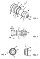
Fig. 2 ein bolzenartiges Teil des Bolzens, -
Fig. 3, 4 verschiedene Ansichten einer Schiebehülse des Bolzens, -
Fig. 5 eine Gewindespindel des Bolzens, -
Fig. 6 eine vergrößerte Ansicht des Details VI derFig. 5 , -
Fig. 7 einen Gewindestift des Bolzens in vergrößerter Ansicht, -
Fig. 8 eine Ansicht des geöffneten Bolzens, -
Fig. 9 einen Schnitt entlang der Linie IX-IX derFig. 8 , -
Fig. 10 eine Ansicht des gespannten Bolzens, -
Fig. 11 einen Schnitt entlang der Linie XI-XI derFig. 10 und -
Fig. 12 eine Ansicht in Richtung des Pfeils XII derFig. 10 .
-
Fig. 1 a perspective view of a bolt, -
Fig. 2 a bolt-like part of the bolt, -
Fig. 3, 4 different views of a sliding sleeve of the bolt, -
Fig. 5 a threaded spindle of the bolt, -
Fig. 6 an enlarged view of the detail VI of theFig. 5 . -
Fig. 7 a threaded pin of the bolt in an enlarged view, -
Fig. 8 a view of the open bolt, -
Fig. 9 a section along the line IX-IX ofFig. 8 . -
Fig. 10 a view of the cocked bolt, -
Fig. 11 a section along the line XI-XI theFig. 10 and -
Fig. 12 a view in the direction of arrow XII theFig. 10 ,
In
Der Bolzen 1 umfasst ein bolzenartiges Teil 2, das in die Öffnungen von in der Zeichnung nicht dargestellten aneinander liegenden Teilen eingeführt werden kann. Das bolzenartige Teil wird in,einem Endbereich von Öffnungen 3 durchdrungen, in welchen Kugeln 4 als Spannelemente radial hin und her bewegbar sind, aufgrund einer nicht dargestellten Umbördelung am äußeren Rand der Öffnungen 3 oder einer anderen Sicherung, wie etwa eines O-Rings, diese jedoch nicht vollständig verlassen können.The bolt 1 comprises a bolt-
Am anderen Endbereich des bolzenartigen Teils 2 ist eine Schiebehülse 5 unverdrehbar, jedoch in Längsrichtung des bolzenartigen Teils 2 verschiebbar angeordnet und überragt das bolzenartige Teil nach außen radial.At the other end region of the bolt-
Im Inneren des bolzenartigen Teils 2 ist eine Bohrung 6 vorgesehen, die im oberen Bereich ein Innengewinde 7 aufweist. In die Bohrung 6 ist eine Gewindespindel 8, die ein entsprechendes Außengewinde 9 aufweist, gegenüber dem bolzenartigen Teil 2 verschraubbar. Die Gewindespindel 8 ragt dabei stirnseitig über das bolzenartige Teil 2 und die Schiebehülse 5 hinaus und ist dort zu einem Handgriff 10 verbreitert. Der Handgriff 10 ist drehfest, gegebenenfalls einstückig mit der Gewindespindel 8 verbunden und weist an seinem stirnseitigen Ende einen Innensechskant 11 zur Aufnahme eines entsprechenden Schlüssels mit Hebelarm auf.Inside the bolt-
Der Handgriff 10 und/oder die Schiebehülse 5 können zur Erhöhung der Griffigkeit gerändelt oder rutschfest beschichtet sein.The
Die Schiebehülse 5 ist in Längsrichtung gegenüber dem bolzenartigen Teil 2 entlang von unrunden, vorzugsweise ebenen Schiebeflächen 12 axial verschiebbar, aufgrund der Unrundheit dieser Schiebeflächen 12 jedoch drehfest mit dem bolzenartigen Teil 2 verbunden. Die Schiebehülse 5 besitzt dabei vorzugsweise den gleichen Außendurchmesser wie der Handgriff 10 und insbesondere einen größeren Außendurchmesser als der Durchmesser der Öffnungen in den aneinander liegenden Teilen, so dass die Schiebehülse 5 mit ihrem stirnseitigen Ende 13 an dem zu verspannenden Teil anliegt.The sliding
In dem stirnseitigen Ende 13 der Schiebehülse 5 kann eine Nut 14 zur Aufnahme eines in der Zeichnung nicht dargestellten O-Rings vorgesehen sein. Dieser O-Ring bewirkt, dass sich die Schiebehülse 5 und damit auch der bolzenartige Teil 2 nicht ohne weiteres auf dem zu verspannenden Teil verdrehen kann.In the
Es ist eine den Weg der Schiebehülse 5 begrenzende Sicherungseinrichtung vorgesehen, die die Schiebehülse 5 auf dem bolzenartigen Teil 2 sichert. Dadurch wird gewährleistet, dass die Schiebehülse 5 auch bei gelöster Gewindespindel 8 nicht ganz von dem bolzenartigen Teil geschoben werden kann. Ein Verkanten der Schiebehülse 5 und damit Probleme bei der Handhabung des Bolzens 1 sind damit ausgeschlossen.It is provided a way the sliding
Wie lediglich in den Schnittdarstellungen der
Die Schiebehülse 5 lässt sich damit auf dem bolzenartigen Teil 2 nur so weit verschieben, bis der Anschlag 16 der Schiebehülse 5 an dem Sicherungsstift 15 ansteht, so dass die Schiebehülse 5 auch bei gelöster Gewindespindel 8 nicht ganz von dem bolzenartigen Teil 2 geschoben werden kann. Ein Verkanten der Schiebehülse 5 und damit Probleme bei der Handhabung des Bolzens 1 sind damit ausgeschlossen.The sliding
Beim Verspannen greift die Gewindespindel 8 mit ihrem, dem Handgriff 10 gegenüberliegenden Ende 17 an den Kugeln 4 an und verschiebt die Kugeln 4 radial nach außen, wozu das Ende 17 gerundet ausgebildet ist. Es versteht sich, dass auch eine andere Formgebung, beispielsweise eine konische Form möglich wäre.When tightening the threaded
Wie insbesondere aus der Detailansicht der
Bei dem in den
Der Bolzen 1 wird gespannt, wie dies in den
Wie sich aus der Darstellung der
- 11
- Bolzenbolt
- 22
- bolzenartiges Teilbolt-like part
- 33
- Öffnungenopenings
- 44
- KugelBullet
- 55
- Schiebehülsesliding sleeve
- 66
- Bohrungdrilling
- 77
- Innengewinde von 2Internal thread of 2
- 88th
- Gewindespindelscrew
- 99
- Außengewinde von 8External thread of 8
- 1010
- Handgriffhandle
- 1111
- InnensechskantAllen
- 1212
- Schiebeflächensliding surfaces
- 1313
- stirnseitiges Ende von 5frontal end of 5
- 1414
- Nutgroove
- 1515
- Sicherungsstiftsafety pin
- 15a15a
- Bohrungendrilling
- 1616
- Anschlag an 5Stop at 5
- 1717
- Ende von 8End of 8
- 1818
- Ausnehmung in 17Recess in 17
- 1919
- Dornmandrel
- 2020
- GewindestiftSet screw
- 2121
- Außengewinde von 20External thread of 20
- 2222
- Innengewinde von 2Internal thread of 2
- 2323
- Innensechskant von 20Hexagon socket of 20
Claims (2)
- Bolt (1) for clamping parts which adjoin one another and which have openings, comprising
a bolt-like part (2) which can be inserted into the openings from one side of the adjoining parts,
a sliding sleeve (5) which is arranged non-rotatably, but displaceably in the longitudinal direction, at one end of the bolt-like part (2) and projects radially outwardly beyond the bolt-like part (2),
a threaded spindle (8) which can be screwed into the bolt-like part (2) in the longitudinal direction, and
at least one clamping element, specifically balls (4) which are arranged at one end inside the bolt-like part (2) and can be moved through at least one opening (3) beyond the outer circumference of the bolt-like part (2),
characterized in that
a mandrel (19) which inwardly delimits the radial possibility of movement of the balls (4) is provided, and the threaded spindle (8) has at its end (17) a recess (18) for the mandrel (19). - Bolt (1) according to Claim 1, characterized in that the mandrel (19) is arranged on a threaded pin (20) which can be connected to, for example screwed into, the bolt-like part (2).
Priority Applications (2)
| Application Number | Priority Date | Filing Date | Title |
|---|---|---|---|
| PL09014833T PL2333357T3 (en) | 2009-11-30 | 2009-11-30 | Bolt for tensioning sections bordering each other |
| EP09014833A EP2333357B1 (en) | 2009-11-30 | 2009-11-30 | Bolt for tensioning sections bordering each other |
Applications Claiming Priority (1)
| Application Number | Priority Date | Filing Date | Title |
|---|---|---|---|
| EP09014833A EP2333357B1 (en) | 2009-11-30 | 2009-11-30 | Bolt for tensioning sections bordering each other |
Publications (2)
| Publication Number | Publication Date |
|---|---|
| EP2333357A1 EP2333357A1 (en) | 2011-06-15 |
| EP2333357B1 true EP2333357B1 (en) | 2012-11-07 |
Family
ID=42115930
Family Applications (1)
| Application Number | Title | Priority Date | Filing Date |
|---|---|---|---|
| EP09014833A Active EP2333357B1 (en) | 2009-11-30 | 2009-11-30 | Bolt for tensioning sections bordering each other |
Country Status (2)
| Country | Link |
|---|---|
| EP (1) | EP2333357B1 (en) |
| PL (1) | PL2333357T3 (en) |
Cited By (1)
| Publication number | Priority date | Publication date | Assignee | Title |
|---|---|---|---|---|
| DE102021004711A1 (en) | 2020-09-11 | 2022-03-17 | Leuteritz Anlagenbau GmbH | Quick-release bolts for a temporary connection of at least two components |
Families Citing this family (2)
| Publication number | Priority date | Publication date | Assignee | Title |
|---|---|---|---|---|
| CN104047938B (en) * | 2014-06-12 | 2016-12-07 | 沈阳飞机工业(集团)有限公司 | Alignment connector |
| CN114450495A (en) * | 2019-11-02 | 2022-05-06 | 贝恩德西格芒公司 | Bolt with adjustable clamping range |
Family Cites Families (8)
| Publication number | Priority date | Publication date | Assignee | Title |
|---|---|---|---|---|
| DE9114220U1 (en) * | 1991-11-15 | 1992-01-09 | Demmeler Maschinenbau Gmbh & Co Kg, 8941 Heimertingen, De | |
| DE29609881U1 (en) * | 1996-06-04 | 1996-08-29 | Rosmann Hanns | Clamping bolt |
| AU5567198A (en) * | 1997-01-20 | 1998-08-07 | Laurence Ross Petrie | Fasteners, clamps, baseplates and modular fixturing |
| DE19727099C2 (en) * | 1997-06-25 | 1999-05-20 | Albert Werlein | Clamping bolt |
| DE19734866C1 (en) * | 1997-08-12 | 1999-02-11 | Demmeler Maschb Gmbh | Connector for two building panels |
| DE19917209C2 (en) * | 1999-04-16 | 2001-09-20 | Bernd Siegmund | Device for clamping superimposed parts |
| DE20104105U1 (en) * | 2001-03-08 | 2001-07-12 | Ludwig Demmeler Gmbh & Co | bolt |
| DE20219317U1 (en) * | 2002-12-12 | 2003-02-20 | Siegmund Bernd | Device for clamping of two parts lying one against the other has operating component in form of threaded spindle engaging in thread in bolt-type component and provided with cup-shaped hand grip |
-
2009
- 2009-11-30 PL PL09014833T patent/PL2333357T3/en unknown
- 2009-11-30 EP EP09014833A patent/EP2333357B1/en active Active
Cited By (1)
| Publication number | Priority date | Publication date | Assignee | Title |
|---|---|---|---|---|
| DE102021004711A1 (en) | 2020-09-11 | 2022-03-17 | Leuteritz Anlagenbau GmbH | Quick-release bolts for a temporary connection of at least two components |
Also Published As
| Publication number | Publication date |
|---|---|
| PL2333357T3 (en) | 2013-04-30 |
| EP2333357A1 (en) | 2011-06-15 |
Similar Documents
| Publication | Publication Date | Title |
|---|---|---|
| EP3177839B1 (en) | Bolt for bracing parts lying on one another | |
| EP3025066B1 (en) | Blind rivet nut for the connection of two components | |
| EP1918596A1 (en) | Blind rivet and use thereof | |
| WO2006094749A1 (en) | Clamping sleeve and clamp connection | |
| DE1810223A1 (en) | Overload clutch with clamping head | |
| EP3206820A1 (en) | Clamping system | |
| DE1085721B (en) | Clamp connection | |
| EP2333357B1 (en) | Bolt for tensioning sections bordering each other | |
| DE19723425A1 (en) | Pulling bolt to connect e.g. welding table and accessories | |
| DE102014224561B3 (en) | chuck | |
| EP2333356B1 (en) | Bolt for tensioning sections bordering each other | |
| EP1896219B1 (en) | Joint | |
| DE102013110983B4 (en) | Connection system | |
| EP2453143A2 (en) | Shearable connecting element | |
| EP1979557B1 (en) | Device for coupling two components | |
| DE202018100101U1 (en) | Mandrel arrangement with Niederzugeffekt | |
| DE3149408A1 (en) | Press-in nut with a moving nut part | |
| WO2004012892A1 (en) | Clamping device for tools | |
| WO2008141736A1 (en) | Device and method for fastening a muzzle brake to a barrel of a weapon | |
| DE3203343A1 (en) | THORN FOR COLD FORGING INTERNAL-PROFILED TUBE BODIES OR CYLINDERS | |
| WO2021083473A1 (en) | Bolt with an adjustable clamping region | |
| DE2534375C2 (en) | Pin-shaped device for resilient tensioning of two components | |
| EP3520965A1 (en) | Expanding mandrel assembly with pulldown effect | |
| DE1188378B (en) | Fastening device | |
| DE605943C (en) | Screw connection of parts made of wood or similar materials using coil springs made of wire |
Legal Events
| Date | Code | Title | Description |
|---|---|---|---|
| PUAI | Public reference made under article 153(3) epc to a published international application that has entered the european phase |
Free format text: ORIGINAL CODE: 0009012 |
|
| AK | Designated contracting states |
Kind code of ref document: A1 Designated state(s): AT BE BG CH CY CZ DE DK EE ES FI FR GB GR HR HU IE IS IT LI LT LU LV MC MK MT NL NO PL PT RO SE SI SK SM TR |
|
| AX | Request for extension of the european patent |
Extension state: AL BA RS |
|
| 17P | Request for examination filed |
Effective date: 20111010 |
|
| GRAP | Despatch of communication of intention to grant a patent |
Free format text: ORIGINAL CODE: EPIDOSNIGR1 |
|
| RIC1 | Information provided on ipc code assigned before grant |
Ipc: F16B 21/16 20060101AFI20120629BHEP |
|
| GRAS | Grant fee paid |
Free format text: ORIGINAL CODE: EPIDOSNIGR3 |
|
| GRAA | (expected) grant |
Free format text: ORIGINAL CODE: 0009210 |
|
| AK | Designated contracting states |
Kind code of ref document: B1 Designated state(s): AT BE BG CH CY CZ DE DK EE ES FI FR GB GR HR HU IE IS IT LI LT LU LV MC MK MT NL NO PL PT RO SE SI SK SM TR |
|
| AX | Request for extension of the european patent |
Extension state: AL BA RS |
|
| REG | Reference to a national code |
Ref country code: GB Ref legal event code: FG4D Free format text: NOT ENGLISH |
|
| REG | Reference to a national code |
Ref country code: CH Ref legal event code: EP Ref country code: AT Ref legal event code: REF Ref document number: 583130 Country of ref document: AT Kind code of ref document: T Effective date: 20121115 |
|
| REG | Reference to a national code |
Ref country code: IE Ref legal event code: FG4D Free format text: LANGUAGE OF EP DOCUMENT: GERMAN |
|
| REG | Reference to a national code |
Ref country code: DE Ref legal event code: R096 Ref document number: 502009005305 Country of ref document: DE Effective date: 20130103 |
|
| REG | Reference to a national code |
Ref country code: NL Ref legal event code: T3 |
|
| REG | Reference to a national code |
Ref country code: LT Ref legal event code: MG4D |
|
| PG25 | Lapsed in a contracting state [announced via postgrant information from national office to epo] |
Ref country code: SE Free format text: LAPSE BECAUSE OF FAILURE TO SUBMIT A TRANSLATION OF THE DESCRIPTION OR TO PAY THE FEE WITHIN THE PRESCRIBED TIME-LIMIT Effective date: 20121107 Ref country code: LT Free format text: LAPSE BECAUSE OF FAILURE TO SUBMIT A TRANSLATION OF THE DESCRIPTION OR TO PAY THE FEE WITHIN THE PRESCRIBED TIME-LIMIT Effective date: 20121107 Ref country code: IS Free format text: LAPSE BECAUSE OF FAILURE TO SUBMIT A TRANSLATION OF THE DESCRIPTION OR TO PAY THE FEE WITHIN THE PRESCRIBED TIME-LIMIT Effective date: 20130307 Ref country code: NO Free format text: LAPSE BECAUSE OF FAILURE TO SUBMIT A TRANSLATION OF THE DESCRIPTION OR TO PAY THE FEE WITHIN THE PRESCRIBED TIME-LIMIT Effective date: 20130207 Ref country code: FI Free format text: LAPSE BECAUSE OF FAILURE TO SUBMIT A TRANSLATION OF THE DESCRIPTION OR TO PAY THE FEE WITHIN THE PRESCRIBED TIME-LIMIT Effective date: 20121107 Ref country code: HR Free format text: LAPSE BECAUSE OF FAILURE TO SUBMIT A TRANSLATION OF THE DESCRIPTION OR TO PAY THE FEE WITHIN THE PRESCRIBED TIME-LIMIT Effective date: 20121107 |
|
| REG | Reference to a national code |
Ref country code: PL Ref legal event code: T3 |
|
| PG25 | Lapsed in a contracting state [announced via postgrant information from national office to epo] |
Ref country code: SI Free format text: LAPSE BECAUSE OF FAILURE TO SUBMIT A TRANSLATION OF THE DESCRIPTION OR TO PAY THE FEE WITHIN THE PRESCRIBED TIME-LIMIT Effective date: 20121107 Ref country code: GR Free format text: LAPSE BECAUSE OF FAILURE TO SUBMIT A TRANSLATION OF THE DESCRIPTION OR TO PAY THE FEE WITHIN THE PRESCRIBED TIME-LIMIT Effective date: 20130208 Ref country code: PT Free format text: LAPSE BECAUSE OF FAILURE TO SUBMIT A TRANSLATION OF THE DESCRIPTION OR TO PAY THE FEE WITHIN THE PRESCRIBED TIME-LIMIT Effective date: 20130307 Ref country code: LV Free format text: LAPSE BECAUSE OF FAILURE TO SUBMIT A TRANSLATION OF THE DESCRIPTION OR TO PAY THE FEE WITHIN THE PRESCRIBED TIME-LIMIT Effective date: 20121107 |
|
| PG25 | Lapsed in a contracting state [announced via postgrant information from national office to epo] |
Ref country code: BG Free format text: LAPSE BECAUSE OF FAILURE TO SUBMIT A TRANSLATION OF THE DESCRIPTION OR TO PAY THE FEE WITHIN THE PRESCRIBED TIME-LIMIT Effective date: 20130207 Ref country code: EE Free format text: LAPSE BECAUSE OF FAILURE TO SUBMIT A TRANSLATION OF THE DESCRIPTION OR TO PAY THE FEE WITHIN THE PRESCRIBED TIME-LIMIT Effective date: 20121107 Ref country code: DK Free format text: LAPSE BECAUSE OF FAILURE TO SUBMIT A TRANSLATION OF THE DESCRIPTION OR TO PAY THE FEE WITHIN THE PRESCRIBED TIME-LIMIT Effective date: 20121107 Ref country code: SK Free format text: LAPSE BECAUSE OF FAILURE TO SUBMIT A TRANSLATION OF THE DESCRIPTION OR TO PAY THE FEE WITHIN THE PRESCRIBED TIME-LIMIT Effective date: 20121107 |
|
| REG | Reference to a national code |
Ref country code: IE Ref legal event code: MM4A |
|
| PG25 | Lapsed in a contracting state [announced via postgrant information from national office to epo] |
Ref country code: RO Free format text: LAPSE BECAUSE OF FAILURE TO SUBMIT A TRANSLATION OF THE DESCRIPTION OR TO PAY THE FEE WITHIN THE PRESCRIBED TIME-LIMIT Effective date: 20121107 |
|
| PLBE | No opposition filed within time limit |
Free format text: ORIGINAL CODE: 0009261 |
|
| STAA | Information on the status of an ep patent application or granted ep patent |
Free format text: STATUS: NO OPPOSITION FILED WITHIN TIME LIMIT |
|
| 26N | No opposition filed |
Effective date: 20130808 |
|
| PG25 | Lapsed in a contracting state [announced via postgrant information from national office to epo] |
Ref country code: IE Free format text: LAPSE BECAUSE OF NON-PAYMENT OF DUE FEES Effective date: 20121130 Ref country code: ES Free format text: LAPSE BECAUSE OF FAILURE TO SUBMIT A TRANSLATION OF THE DESCRIPTION OR TO PAY THE FEE WITHIN THE PRESCRIBED TIME-LIMIT Effective date: 20130218 |
|
| PG25 | Lapsed in a contracting state [announced via postgrant information from national office to epo] |
Ref country code: MT Free format text: LAPSE BECAUSE OF FAILURE TO SUBMIT A TRANSLATION OF THE DESCRIPTION OR TO PAY THE FEE WITHIN THE PRESCRIBED TIME-LIMIT Effective date: 20121107 Ref country code: CY Free format text: LAPSE BECAUSE OF FAILURE TO SUBMIT A TRANSLATION OF THE DESCRIPTION OR TO PAY THE FEE WITHIN THE PRESCRIBED TIME-LIMIT Effective date: 20121107 |
|
| REG | Reference to a national code |
Ref country code: DE Ref legal event code: R097 Ref document number: 502009005305 Country of ref document: DE Effective date: 20130808 |
|
| PG25 | Lapsed in a contracting state [announced via postgrant information from national office to epo] |
Ref country code: MC Free format text: LAPSE BECAUSE OF NON-PAYMENT OF DUE FEES Effective date: 20121130 |
|
| PG25 | Lapsed in a contracting state [announced via postgrant information from national office to epo] |
Ref country code: SM Free format text: LAPSE BECAUSE OF FAILURE TO SUBMIT A TRANSLATION OF THE DESCRIPTION OR TO PAY THE FEE WITHIN THE PRESCRIBED TIME-LIMIT Effective date: 20121107 Ref country code: LU Free format text: LAPSE BECAUSE OF NON-PAYMENT OF DUE FEES Effective date: 20121130 |
|
| GBPC | Gb: european patent ceased through non-payment of renewal fee |
Effective date: 20131130 |
|
| PG25 | Lapsed in a contracting state [announced via postgrant information from national office to epo] |
Ref country code: HU Free format text: LAPSE BECAUSE OF FAILURE TO SUBMIT A TRANSLATION OF THE DESCRIPTION OR TO PAY THE FEE WITHIN THE PRESCRIBED TIME-LIMIT Effective date: 20091130 |
|
| PG25 | Lapsed in a contracting state [announced via postgrant information from national office to epo] |
Ref country code: GB Free format text: LAPSE BECAUSE OF NON-PAYMENT OF DUE FEES Effective date: 20131130 |
|
| PG25 | Lapsed in a contracting state [announced via postgrant information from national office to epo] |
Ref country code: MK Free format text: LAPSE BECAUSE OF FAILURE TO SUBMIT A TRANSLATION OF THE DESCRIPTION OR TO PAY THE FEE WITHIN THE PRESCRIBED TIME-LIMIT Effective date: 20121107 |
|
| REG | Reference to a national code |
Ref country code: FR Ref legal event code: PLFP Year of fee payment: 7 |
|
| REG | Reference to a national code |
Ref country code: FR Ref legal event code: PLFP Year of fee payment: 8 |
|
| REG | Reference to a national code |
Ref country code: FR Ref legal event code: PLFP Year of fee payment: 9 |
|
| REG | Reference to a national code |
Ref country code: FR Ref legal event code: PLFP Year of fee payment: 10 |
|
| PGFP | Annual fee paid to national office [announced via postgrant information from national office to epo] |
Ref country code: CZ Payment date: 20230913 Year of fee payment: 15 |
|
| PGFP | Annual fee paid to national office [announced via postgrant information from national office to epo] |
Ref country code: NL Payment date: 20231126 Year of fee payment: 15 |
|
| PGFP | Annual fee paid to national office [announced via postgrant information from national office to epo] |
Ref country code: TR Payment date: 20231006 Year of fee payment: 15 Ref country code: IT Payment date: 20231129 Year of fee payment: 15 Ref country code: FR Payment date: 20231121 Year of fee payment: 15 Ref country code: DE Payment date: 20231002 Year of fee payment: 15 Ref country code: CH Payment date: 20231202 Year of fee payment: 15 Ref country code: AT Payment date: 20231003 Year of fee payment: 15 |
|
| PGFP | Annual fee paid to national office [announced via postgrant information from national office to epo] |
Ref country code: PL Payment date: 20231121 Year of fee payment: 15 Ref country code: BE Payment date: 20231024 Year of fee payment: 15 |